
Dynamic Low Voltage Ride through Detection and Mitigation in Brushless Doubly Fed Induction Generators

 , ,
, ,
Abstract
:
1. Introduction
- The equivalent circuit of a brushless doubly-fed induction generator is used to develop an analytical model of the voltage drop at the PCC in the presence of a short circuit fault. The effect of the reactive current reference value on the PCC voltage drop (as seen from the rotor side converter in the event of a short-circuit fault) is then analyzed using the analytical model.
- Insights gained from the analytical model of a brushless doubly-fed induction generator in the presence of a short circuit fault are used to propose a rotor side converter reactive current control scheme to minimize the voltage drop at the PCC. This is done by analyzing the effect of using the load current value as a reference to minimize the overall voltage drop magnitude at the PCC. To the best of the authors’ knowledge, this is the first work on using an analytical model of the voltage drop to design the rotor side converter controller.
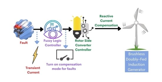
- To improve the rotor side converter’s response to faults and reduce the latency of detecting the onset of a fault, a fuzzy logic controller is proposed with voltage magnitude and frequency (at the power winding) used as the two inputs. The proposed fuzzy logic controller is then used to turn on the rotor side converter’s compensation mode if a fault is detected. To the best of the authors’ knowledge, this is the first work on using voltage magnitude and frequency to detect faults using a fuzzy logic controller.
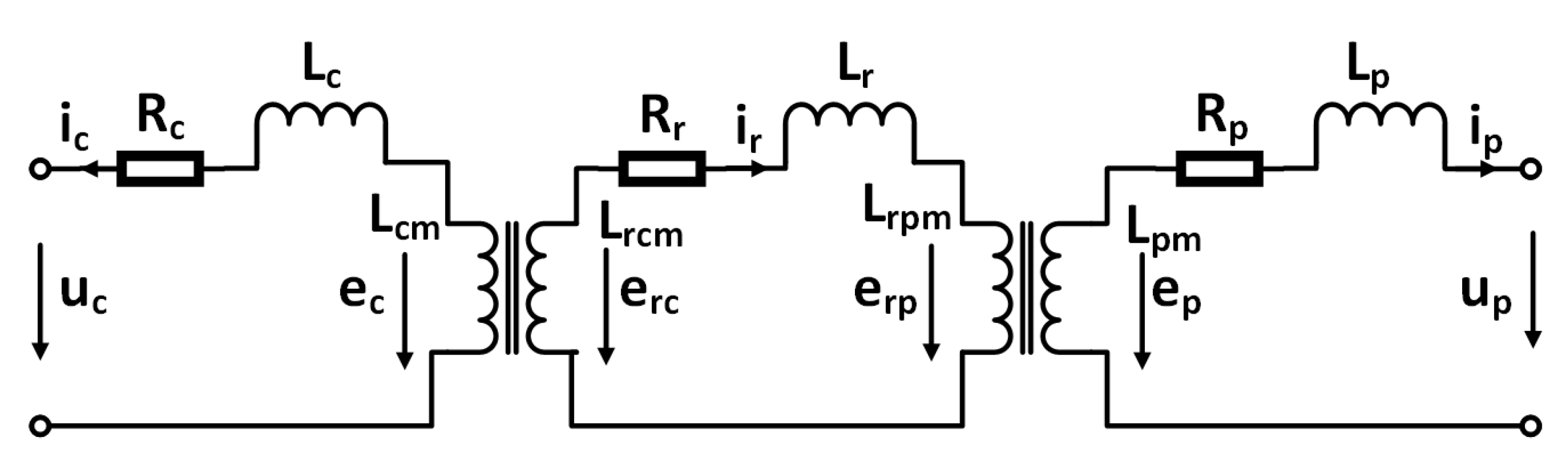
2. System Model
3. Proposed Technique
3.1. Fuzzy Logic Controller
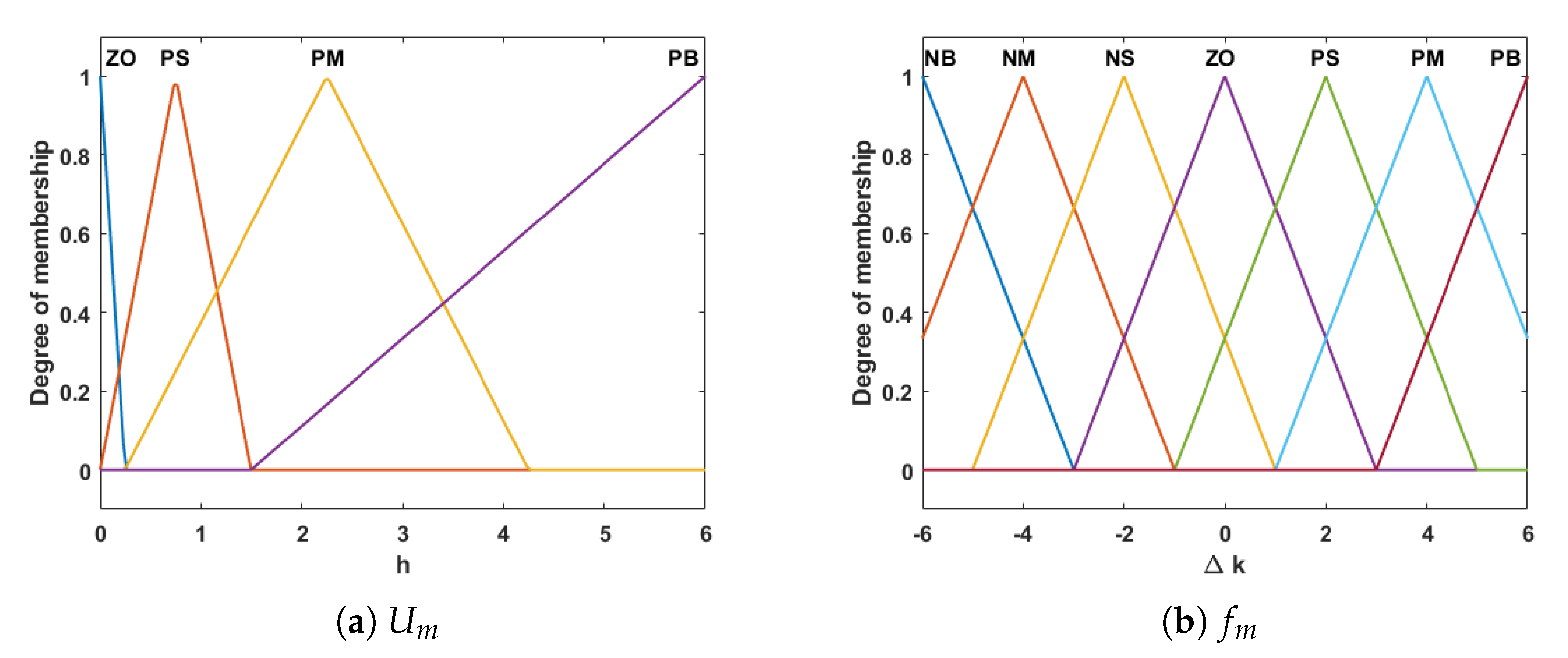
3.2. Fuzzification
3.3. Knowledge Base
- If there is no voltage drop and no change in frequency, then the rotor side converter should run in normal mode.
- If there is no voltage drop but the change in frequency is large then the compensation mode of rotor side converter should be turned on.
- If the voltage drop is large and there is no change in frequency, then the compensation mode of rotor side converter should be turned on.
- If the voltage drop is large and the frequency has changed, then the compensation mode of rotor side converter should be turned on.
3.4. Inference Engine
- If is PS with grade 0.7467 and is with grade 1.0, then is PS with grade 0.7467 = min(0.7467, 1.0).
- If is PM with grade 0.1550 and is with grade 1.0, then is PM with grade 0.1550 = min(0.1550, 1.0).
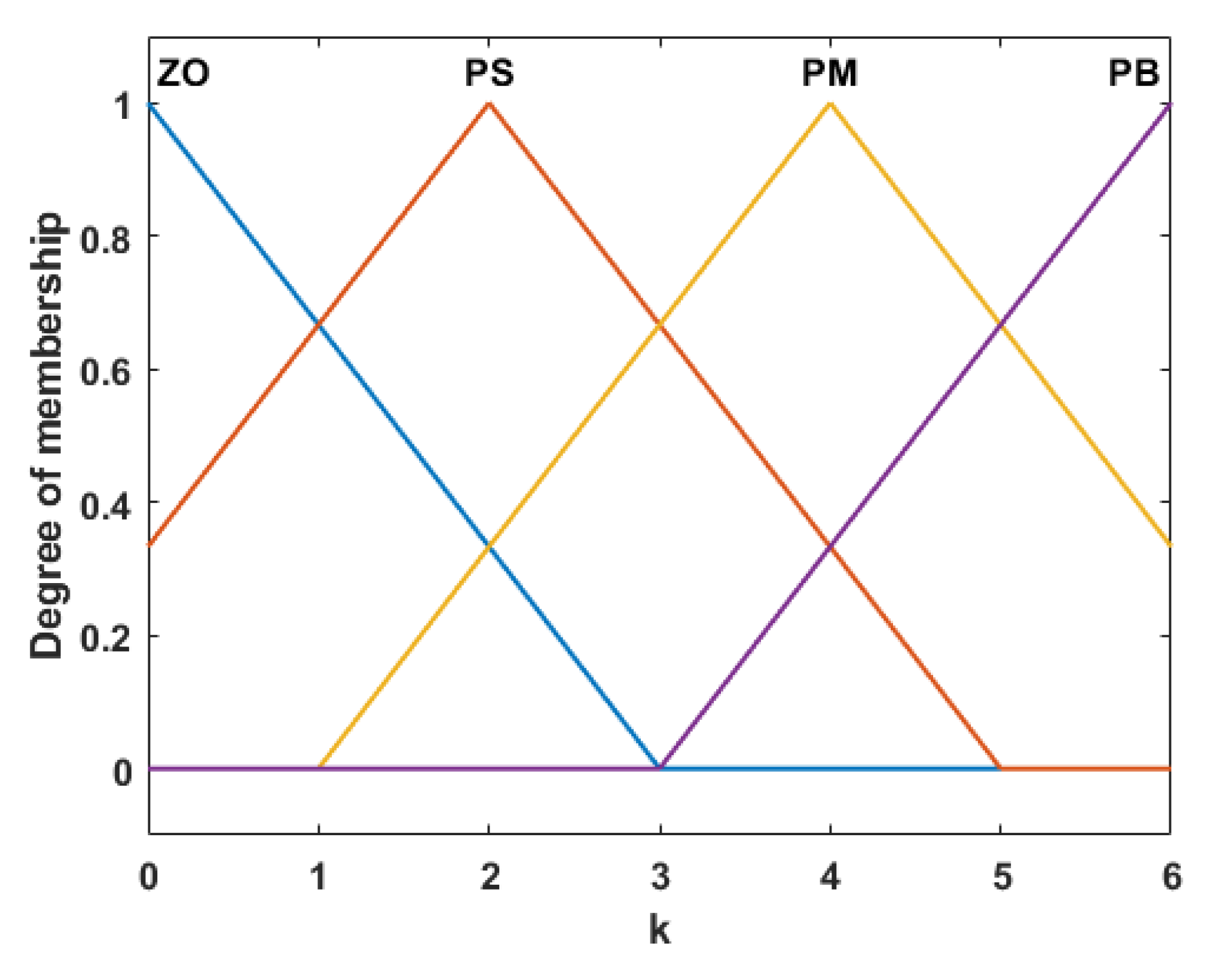
3.5. Defuzzification
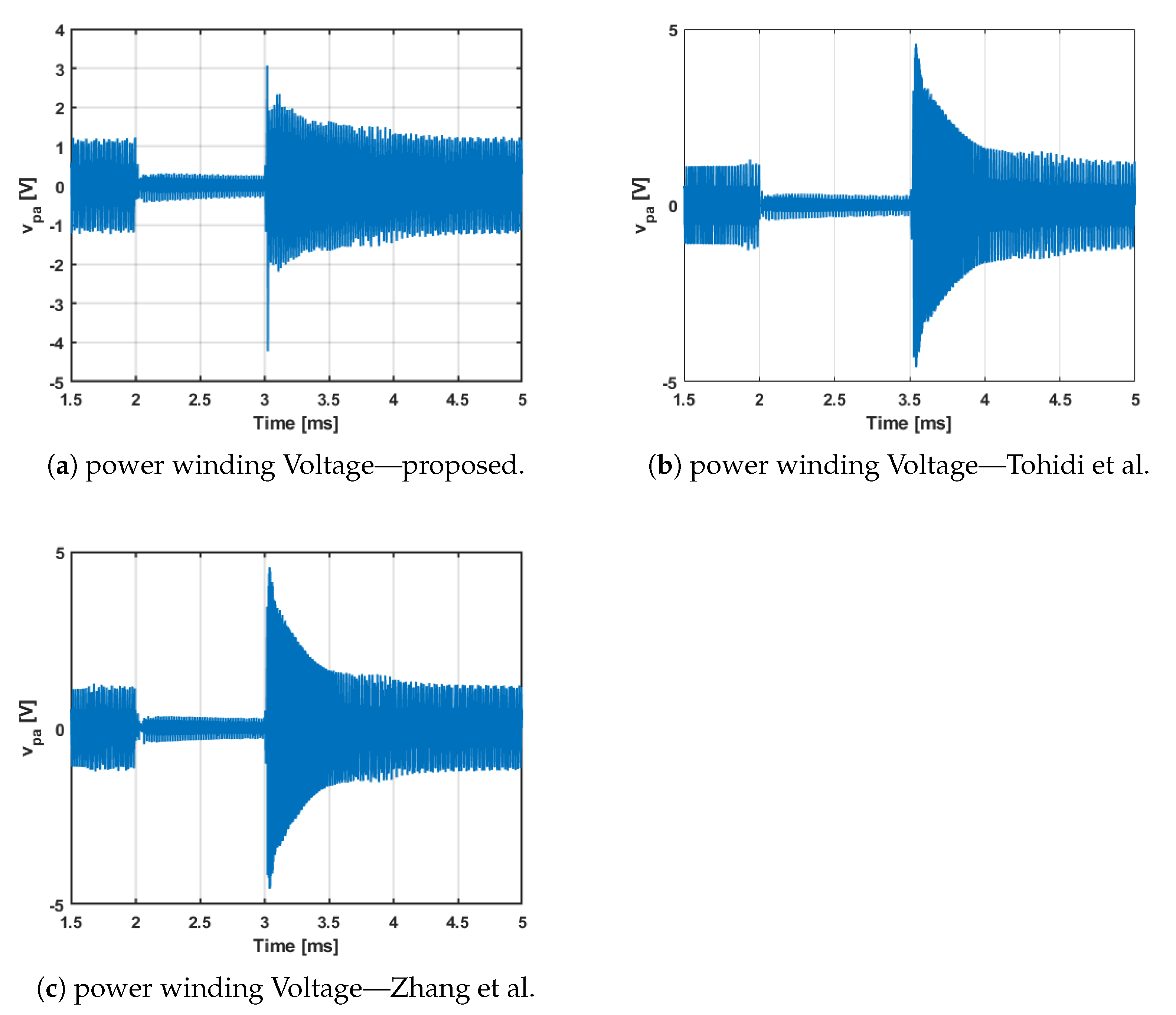
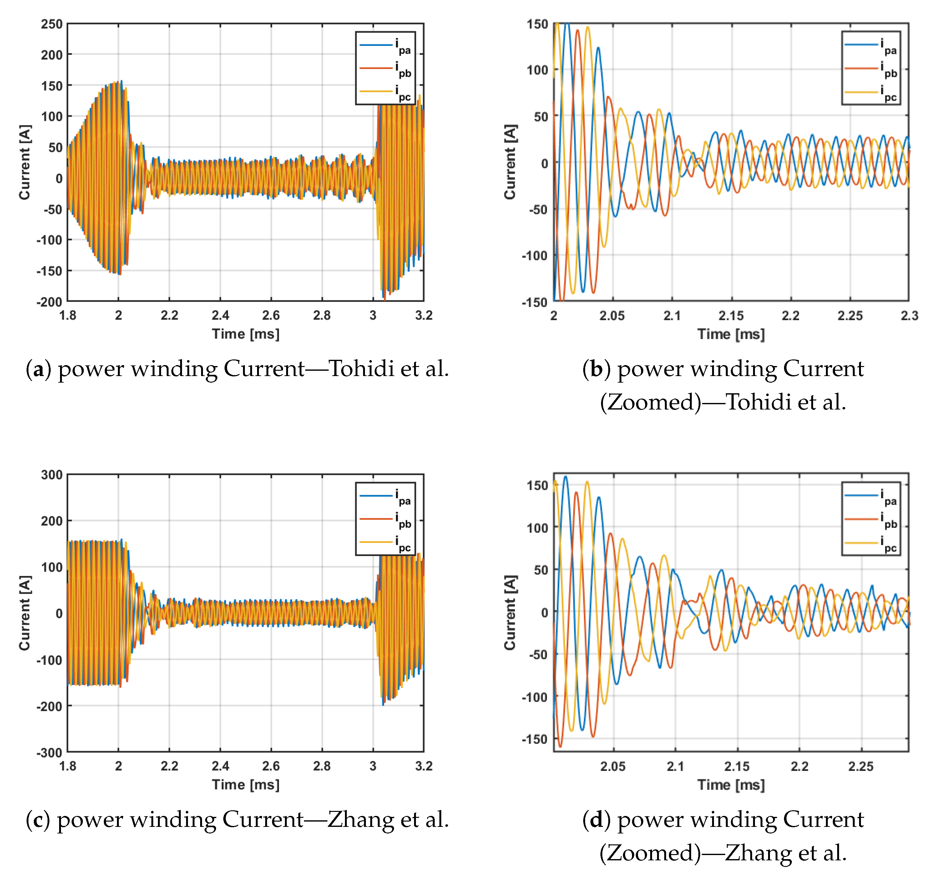
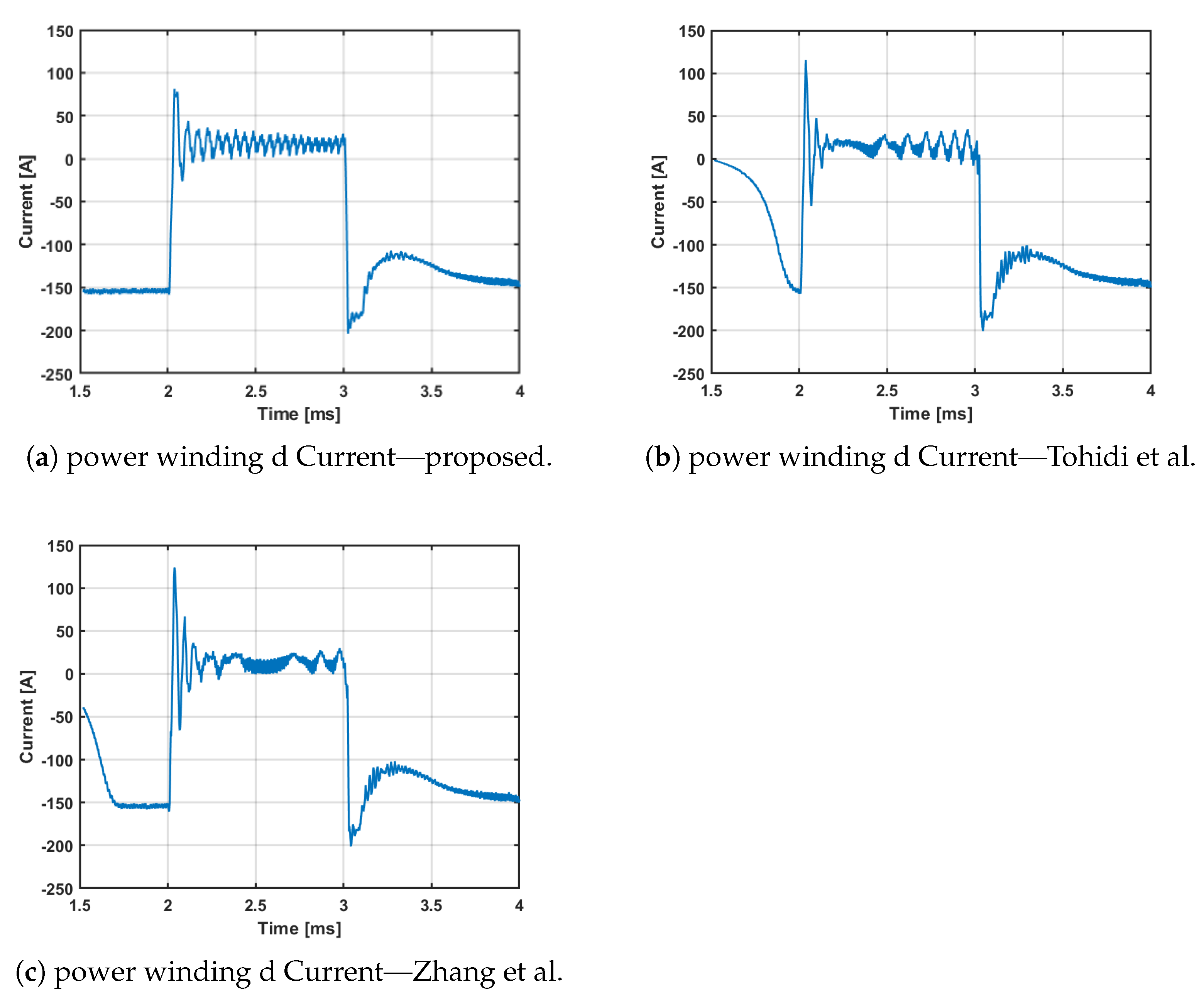
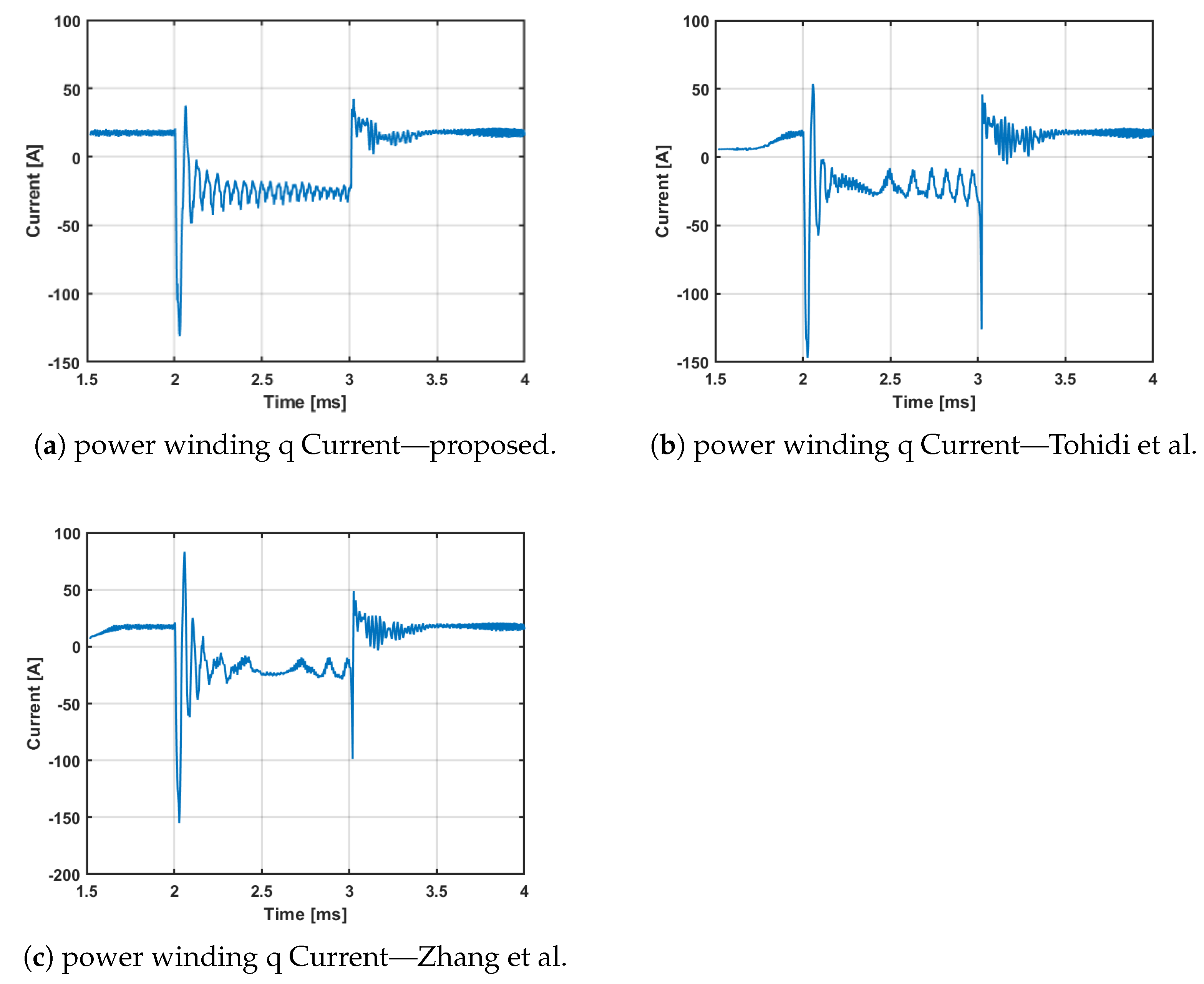
4. Results and Discussion
5. Conclusions
Author Contributions
Funding
Institutional Review Board Statement
Informed Consent Statement
Data Availability Statement
Acknowledgments
Conflicts of Interest
References
- Mohammed, O.O.; Mustafa, M.W.; Aman, M.N.; Salisu, S.; Otuoze, A.O. Capacity benefit margin assessment in the presence of renewable energy. Int. Trans. Electr. Energy Syst. 2020, 30, etep12502. [Google Scholar] [CrossRef]
- Mohammed, O.O.; Mustafa, M.W.; Aman, M.N. A Graph-Theoretic Approach to Capacity Benefit Margin Calculation for Large Multiarea Power Systems. IEEE Syst. J. 2020, 14, 1230–1233. [Google Scholar] [CrossRef]
- Moazen, M.; Kazemzadeh, R.; Azizian, M.R. Model-based predictive direct power control of brushless doubly fed reluctance generator for wind power applications. Alex. Eng. J. 2016, 55, 2497–2507. [Google Scholar] [CrossRef] [Green Version]
- Larik, R.M.; Mustafa, M.W.; Aman, M.N.; Jumani, T.A.; Sajid, S.; Panjwani, M.K. An Improved Algorithm for Optimal Load Shedding in Power Systems. Energies 2018, 11, 1808. [Google Scholar] [CrossRef] [Green Version]
- Larik, R.M.; Mustafa, M.W.; Aman, M.N. A critical review of the state-of-art schemes for under voltage load shedding. Int. Trans. Electr. Energy Syst. 2019, 29, e2828. [Google Scholar] [CrossRef] [Green Version]
- Tohidi, S.; Oraee, H.; Zolghadri, M.R.; Shao, S.; Tavner, P. Analysis and enhancement of low-voltage ride-through capability of brushless doubly fed induction generator. IEEE Trans. Ind. Electron. 2013, 60, 1146–1155. [Google Scholar] [CrossRef] [Green Version]
- Tohidi, S.; Abdi, E.; Shao, S.; Zolghadri, M.; McMahon, R.; Tavner, P.; Oraee, H. Low voltage ride-through of DFIG and brushless DFIG: Similarities and differences. Electr. Power Syst. Res. 2014, 110, 64–72. [Google Scholar] [CrossRef]
- Gholizadeh, M.; Tohidi, S.; Oraee, A.; Oraee, H. Appropriate crowbar protection for improvement of brushless DFIG LVRT during asymmetrical voltage dips. Int. J. Electr. Power Energy Syst. 2018, 95, 1–10. [Google Scholar] [CrossRef]
- Döşoğlu, M.K. Crowbar hardware design enhancement for fault ride through capability in doubly fed induction generator-based wind turbines. ISA Trans. 2020, 104, 321–328. [Google Scholar] [CrossRef]
- Das, J.C. Effects of harmonics. In Power System Harmonics and Passive Filter Designs; John Wiley & Sons: Hoboken, NJ, USA, 2015; pp. 331–378. [Google Scholar]
- Shao, S.; Long, T.; Abdi, E.; Mcmahon, R.A. Dynamic Control of the Brushless Doubly Fed Induction Generator Under Unbalanced Operation. IEEE Trans. Ind. Electron. 2013, 60, 2465–2476. [Google Scholar] [CrossRef]
- Long, T.; Shao, S.; Abdi, E.; McMahon, R.A.; Liu, S. Asymmetrical low-voltage ride through of brushless doubly fed induction generators for the wind power generation. IEEE Trans. Energy Convers. 2013, 28, 502–511. [Google Scholar] [CrossRef]
- Long, T.; Shao, S.; Malliband, P.; Abdi, E.; McMahon, R.A. Crowbarless fault ride-through of the brushless doubly fed induction generator in a wind turbine under symmetrical voltage dips. IEEE Trans. Ind. Electron. 2013, 60, 2833–2841. [Google Scholar] [CrossRef]
- Tohidi, S.; Oraee, H.; Zolghadri, M.R.; Rahimi, M. A control scheme to enhance low voltage ride-through of brushless doubly-fed induction generators. Wind Energy 2016, 19, 1699–1712. [Google Scholar] [CrossRef]
- Huang, J.; Li, S. Analytical expression for LVRT of BDFIG with enhanced current control to CW and reactive power support from GSC. Int. J. Electr. Power Energy Syst. 2018, 98, 243–255. [Google Scholar] [CrossRef]
- Hang, C.; Wang, X.; Liu, N.; Kong, M.; Nie, P.; Li, Z. Virtual inductance control strategy for brushless doubly-fed induction generator during grid voltage dips. In Proceedings of the 2018 21st International Conference on Electrical Machines and Systems (ICEMS), Jeju, Korea, 7–10 October 2018; pp. 1533–1537. [Google Scholar]
- Zhang, A.; Chen, Z.; Gao, R.; Wang, J.; Ma, Z.; Wang, S.; Wang, Y. Crowbarless Symmetrical Low-Voltage Ride Through Based on Flux Linkage Tracking For Brushless Doubly Fed Induction Generators. IEEE Trans. Ind. Electron. 2020, 67, 7606–7616. [Google Scholar] [CrossRef]
- Lu, M.; Chen, Y.; Zhang, D.; Su, J.; Kang, Y. Virtual Synchronous Control Based on Control Winding Orientation for Brushless Doubly Fed Induction Generator (BDFIG) Wind Turbines Under Symmetrical Grid Faults. Energies 2019, 12, 319. [Google Scholar] [CrossRef] [Green Version]
- Shao, S.; Long, T.; Abdi, E.; McMahon, R.; Wu, Y. Symmetrical low voltage ride-through of the brushless doubly-fed induction generator. In Proceedings of the IECON 2011—37th Annual Conference of the IEEE Industrial Electronics Society, Melbourne, Australia, 7–10 November 2011; pp. 3209–3214. [Google Scholar] [CrossRef]
- Wang, X.; Lin, H.; Wang, Z. Transient Control of the Reactive Current for the Line-Side Converter of the Brushless Doubly-Fed Induction Generator in Stand-Alone Operation. IEEE Trans. Power Electron. 2017, 32, 8193–8203. [Google Scholar] [CrossRef]
- Zhang, R.; Phillis, Y.A.; Kouikoglou, V.S. Fuzzy Control of Queuing Systems; Springer: London, UK, 2005; pp. 1–175. [Google Scholar]
- Altas, I.H. Fuzzy Logic Control in Energy Systems with Design Applications in MATLAB®/Simulink®; The Institute of Engineering & Technology: London, UK, 2017. [Google Scholar] [CrossRef]
- Sadeghi, R.; Madani, S.M.; Ataei, M. A New Smooth Synchronization of Brushless Doubly-Fed Induction Generator by Applying a Proposed Machine Model. IEEE Trans. Sustain. Energy 2018, 9, 371–380. [Google Scholar] [CrossRef]
- Perelmuter, V. Simulation with Sumulink and SimPowerSystems. In Renewable Energy Systems; CRC Press: Boca Raton, FL, USA, 2017. [Google Scholar]
- Zhang, J.; Ding, H.; Wang, B.; Guo, X.; Padmanaban, S. Active Power Decoupling for Current Source Converters: An Overview Scenario. Electronics 2019, 8, 197. [Google Scholar] [CrossRef] [Green Version]
- Memon, A.; Mustafa, M.W.; Aman, M.N.; Hafeez, A.; Ullah, M. Improving Transient Behavior of a Brushless Doubly Fed Induction Generator through Reactive Current Control of Grid-Side Converter. Electronics 2021, 10, 1413. [Google Scholar] [CrossRef]
- Qoria, T.; Guillaud, X. Chapter 8—Control of power electronics-driven power sources. In Converter-Based Dynamics and Control of Modern Power Systems; Monti, A., Milano, F., Bompard, E., Guillaud, X., Eds.; Academic Press: Cambridge, MA, USA, 2021; pp. 193–234. [Google Scholar] [CrossRef]
- Khidrani, A.; Habibuddin, M.H.; Mustafa, M.W.; Aman, M.N.; Mokhtar, A.S. A hybrid voltage-current compensator using a synchronous reference frame technique for grid-connected microgrid under nonlinear load conditions. Int. Trans. Electr. Energy Syst. 2020, 30, e12530. [Google Scholar] [CrossRef]
- Nhlapo, B.; Awodele, K. Review and comparison of the South African grid code requirements for wind generation with the European countries’ grid codes. In Proceedings of the 2020 International SAUPEC/RobMech/PRASA Conference, Cape Town, South Africa, 29–31 January 2020; pp. 1–6. [Google Scholar]
- Ross, T. Fuzzy Logic with Engineering Applications; Wiley: Hoboken, NJ, USA, 2010. [Google Scholar] [CrossRef]
- Ofoli, A.R. 36—Fuzzy-logic applications in electric drives and power electronics. In Power Electronics Handbook, 4th ed.; Rashid, M.H., Ed.; Butterworth-Heinemann: Oxford, UK, 2018; pp. 1221–1243. [Google Scholar]
- Shahbazova, S.N.; Sugeno, M.; Kacprzyk, J. Recent Developments in Fuzzy Logic and Fuzzy Sets; Studies in Fuzziness and Soft Computing; Springer Nature Switzerland: Cham, Switzerland, 2020. [Google Scholar]


| Feature | [8] | [7] | [6] | [14] | [12] | [13] | [20] | Proposed |
|---|---|---|---|---|---|---|---|---|
| DC-link Control |  |  | | | | | | |
| Crowbarless Design | | | | | | | | |
| PCC Voltage Drop Reduction | | | | | | | | |
| Dynamic Reference values | | | | | | | | |
| Fault Detection | | | | | | | | |
| – DC-link Control: Can the technique perform DC-link voltage control? | ||||||||
| – Crowbarless Design: The technique does not require a crowbar? | ||||||||
| – PCC Voltage Drop Reduction: Does the technique reduce the voltage drop at the PCC? | ||||||||
| – Dynamic Reference Value: Does the technique use dynamic reference values for control winding current? | ||||||||
| – Fault Detection: Does the technique provide fault detection (other than hysteresis comparison)? | ||||||||
| Notation | Description |
|---|---|
| PCC | Point of common coupling |
| LVRT | Low voltage ride through |
| , , | Speeds of stator power winding, control winding, and Rotor |
| Natural frequency | |
| , , | Three phase stator power winding voltage |
| , , | Three phase stator control winding voltage |
| , , | Three phase stator power winding voltage at PCC |
| DC-link voltage | |
| , , | Three phase rotor side converter voltage |
| , , | Three phase grid side converter voltage |
| , , | Three phase stator power winding current |
| , , | Three phase stator control winding current |
| , , | Three phase load current |
| , , | Three phase grid current |
| DC-link capacitor | |
| capacitor bank | |
| , | Filter, load inductance |
| , | Internal, load resistance |
| , , | Stator power winding, control winding, and rotor resistance |
| , , | Stator power winding, control winding, and rotor leakage inductance |
| , | Magnetizing inductance of rotor to power winding/control winding |
| Rule # | Rule # | ||||||
|---|---|---|---|---|---|---|---|
| 1 | ZO | ZO | ZO | 9 | ZO | PM | NM |
| 2 | PS | ZO | PS | 10 | PS | PM | NS |
| 3 | PM | ZO | PM | 11 | PM | PM | ZO |
| 4 | PB | ZO | PB | 12 | PB | PM | PS |
| 5 | ZO | PS | NS | 13 | ZO | PB | NB |
| 6 | PS | PS | ZO | 14 | PS | PB | NM |
| 7 | PM | PS | PS | 15 | PM | PB | NS |
| 8 | PB | PS | PM | 16 | PB | PB | ZO |
| Parameter | Value |
|---|---|
| Rated Power | 40 kVA |
| Power factor | 0.8 |
| Rated Stator power winding Voltage | 120 V |
| Rated stator power winding current | 150 A |
| Rated operating frequency | 50 Hz |
| Switching frequency | 4 KHz |
| , | 2, 6 |
| 475 rpm | |
| , | 0.01 F, 700 V |
| , , , | 0.214 p.u., 0.0715 p.u., 0.0122 p.u., 0.0133 p.u. |
| , , | 0.017 p.u., 0.0108 p.u., 0.047 p.u. |
| , | 19.223 p.u., 5.035 p.u. |
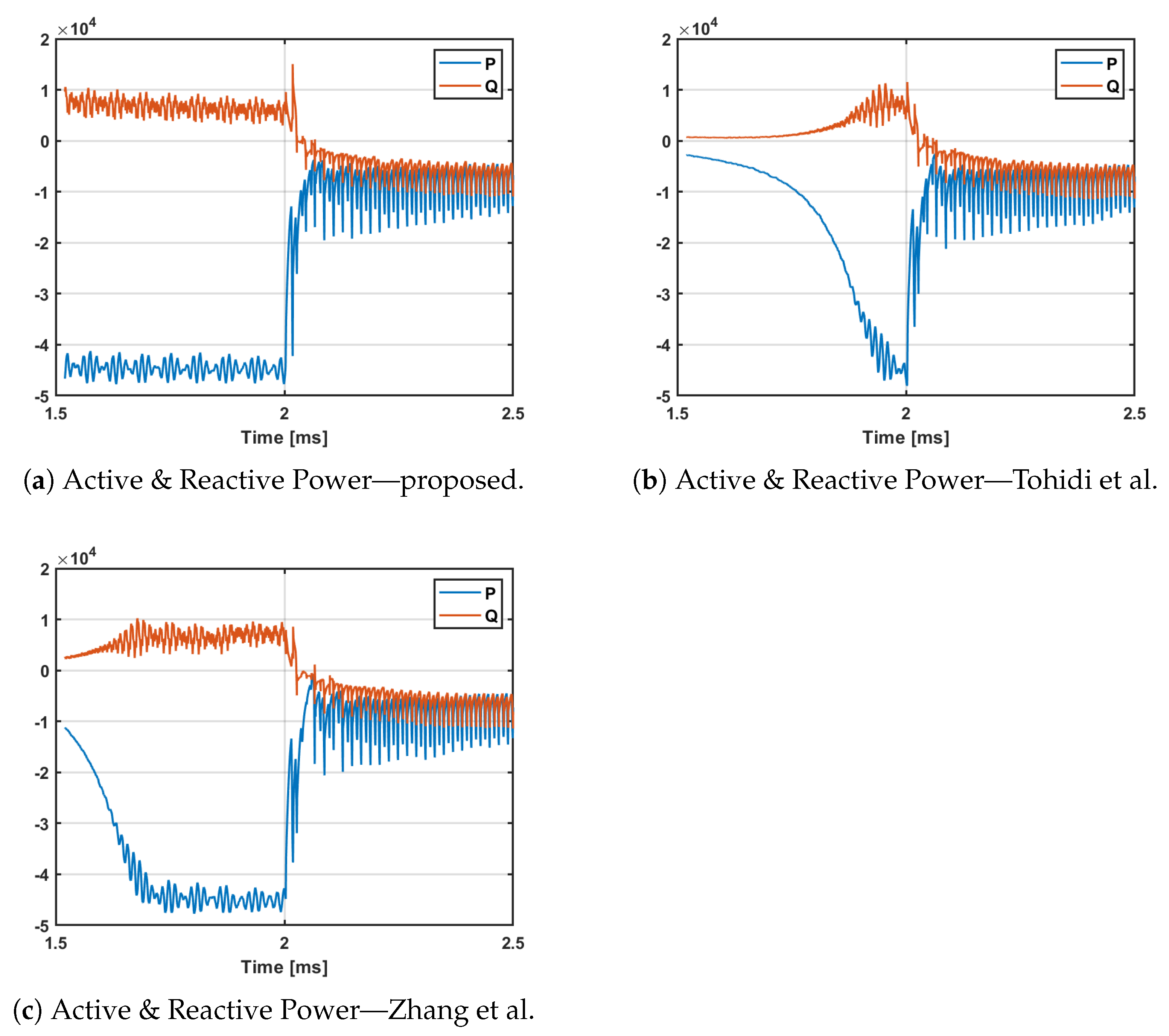
| THD | Settling Time | Voltage-Drop | |
|---|---|---|---|
| Tohidi et al. | 36.2% | 2.340 ms | 0.85 p.u. |
| Zhang et al. | 34.5% | 2.272 ms | 0.84 p.u. |
| Proposed | 22.5% | 2.167 ms | 0.73 p.u. |
| Minimum Improvement | 12% | 0.105 ms | 0.11 p.u. |
Publisher’s Note: MDPI stays neutral with regard to jurisdictional claims in published maps and institutional affiliations. |
© 2021 by the authors. Licensee MDPI, Basel, Switzerland. This article is an open access article distributed under the terms and conditions of the Creative Commons Attribution (CC BY) license (https://creativecommons.org/licenses/by/4.0/).
Share and Cite
Memon, A.; Mustafa, M.W.; Aman, M.N.; Ullah, M.; Kamal, T.; Hafeez, A. Dynamic Low Voltage Ride through Detection and Mitigation in Brushless Doubly Fed Induction Generators. Energies 2021, 14, 4461. https://doi.org/10.3390/en14154461
Memon A, Mustafa MW, Aman MN, Ullah M, Kamal T, Hafeez A. Dynamic Low Voltage Ride through Detection and Mitigation in Brushless Doubly Fed Induction Generators. Energies. 2021; 14(15):4461. https://doi.org/10.3390/en14154461
Chicago/Turabian StyleMemon, Ahsanullah, Mohd Wazir Mustafa, Muhammad Naveed Aman, Mukhtar Ullah, Tariq Kamal, and Abdul Hafeez. 2021. "Dynamic Low Voltage Ride through Detection and Mitigation in Brushless Doubly Fed Induction Generators" Energies 14, no. 15: 4461. https://doi.org/10.3390/en14154461
APA StyleMemon, A., Mustafa, M. W., Aman, M. N., Ullah, M., Kamal, T., & Hafeez, A. (2021). Dynamic Low Voltage Ride through Detection and Mitigation in Brushless Doubly Fed Induction Generators. Energies, 14(15), 4461. https://doi.org/10.3390/en14154461