Abstract
There is a necessity to design a three-phase squirrel cage induction motor (SCIM) for high-speed applications with a larger air gap length in order to limit the distortion of air gap flux density, the thermal expansion of stator and rotor teeth, centrifugal forces, and the magnetic pull. To that effect, a larger air gap length lowers the power factor, efficiency, and torque density of a three-phase SCIM. This should inform motor design engineers to take special care during the design process of a three-phase SCIM by selecting an air gap length that will provide optimal performance. This paper presents an approach that would assist with the selection of an optimal air gap length (OAL) and optimal capacitive auxiliary stator winding (OCASW) configuration for a high torque per ampere (TPA) three-phase SCIM. A genetic algorithm (GA) assisted by finite element analysis (FEA) is used in the design process to determine the OAL and OCASW required to obtain a high torque per ampere without compromising the merit of achieving an excellent power factor and high efficiency for a three-phase SCIM. The performance of the optimized three-phase SCIM is compared to unoptimized machines. The results obtained from FEA are validated through experimental measurements. Owing to the penalty functions related to the value of objective and constraint functions introduced in the genetic algorithm model, both the FEA and experimental results provide evidence that an enhanced torque per ampere three-phase SCIM can be realized for a large OAL and OCASW with high efficiency and an excellent power factor in different working conditions.
1. Introduction
A SCIM requires reactive power for operation. Thus, its power factor is intrinsically poor, and it is especially worse when starting or operating under a condition of light load [1]. The power factor of a SCIM is also poor when operating with an electronic converter, and the improvement of the power factor of the SCIM requires a mode of reactive power compensation [1,2]. In the last decade, the use of an auxiliary winding on a stator that is magnetically coupled to the primary winding has been put forward as a means to improve a SCIM’s power factor [3,4,5,6,7,8,9,10,11]. Although various works have detailed the use of an auxiliary winding on a stator which is connected to a capacitor bank to have tremendously improved the power factor, notable effects on machine efficiency and torque per ampere have been observed [2]. The previous works reported in [1,2] demonstrated that the effect of the variation in air gap length is more significant regarding the efficiency rather than the power factor, and that the effect of the variation of auxiliary capacitive winding is more significant on the power factor and the torque per ampere than efficiency. The selection of an OAL and OCASW that would provide a high TPA without compromising the merit of achieving an excellent power factor and high efficiency for a three-phase SCIM is thus necessary. The selection of an OAL and OCASW can be achieved using an optimization process.
In the last few decades, designers have approached the optimum design of electrical machines as a general nonlinear programing problem [12], and the optimization of SCIM design is usually formulated as such. There are different types of the optimization models for electrical machines. As far as the numbers of objectives are concerned, there are single and multi-objective models. From the perspective of manufacturing quality, there are deterministic and robust optimization models [13]. Optimal search algorithms can be divided into two categories: deterministic methods that find optima algorithmically and stochastic methods that explore the solution space randomly [14]. Additionally, design optimization may be modeled with a scalar or vector objective. The latter employs a fitness function with a set of satisfactory solutions, while the first employs a fitness function with a unique solution [14].
In this paper, the focus is finding a unique solution to the optimization problem, where either deterministic or stochastic methods may be used. Although there is a large variety of deterministic methods, the most popular method is the sequential unconstrained minimization technique (SUMT) [15]. The SUMT first converts a constrained optimization problem into an unconstrained one using a penalty function and then applies sequential nonlinear programming for optimization. The technique is able to find an optimum in just a few iterations but requires gradient calculation [14,16]. On the other hand, stochastic methods require greater design candidate evaluations but are free from gradients and, in principle, not trapped by local minima. Furthermore, population-based searches in stochastic methods can take advantage of parallel computing [17]. This is the case for genetic algorithm (GA), simulated annealing (SA), particle swam optimization (PSO), and bacteria foraging (BF) methods, among others.
In [18], three advanced versions of a PSO were used to estimate the equivalent parameters of a three-phase squirrel cage induction motor. In PSO, the best search is attained by a combination of self and swarm knowledge, and it can be used for an iterative calculation of the objective functions [19]. SA optimization emulates a physical process whereby a solid is first heated and then gradually cooled [20]. This method has good capability for finding a global minima but is not efficient at searching a large solution space [14]. BF is inspired by the behavior of bacteria and is reported to have good capabilities in terms of finding a global optimum [21]. BF has not yet been actively applied to machine design optimization but shows great potential based on its successful application in other related fields [22,23]. GA optimization techniques are based on natural selection, i.e., the process that drives biological evolution and repeatedly modifies a population of initial solutions [24,25,26,27]. A GA optimization technique offers a convenient method to handle constraints and single or multi-objective functions [24,25,26]. A GA simultaneously searches for a set of points, not a single point, and follows the rules of probability instead of definitive rules. Additionally, a GA acts on a code set rather than original values and it does not require a derivative function, which is hard to obtain. A GA only requires a purpose function and a method for fitting information [27]. For optimization problems, GAs provide the best solutions within the search space [28,29]. A GA is opted to solve the optimization problem in this paper due to the high degree of sensitivity associated with the variation of the air gap length and auxiliary capacitance value. The use of binary code rather than the original values of the air gap length and auxiliary capacitance values, and the avoidance of derivative function, make a GA a good fit in the search process for optima.
Although this paper is an advanced work based on the analysis outlined in [1,2], it presents an optimization method that would assist with the determination of an OAL and OCASW for an enhanced torque per ampere three-phase SCIM suitable for high-speed applications. It further elaborates on an analytical approach that describes the engineering problem and its solutions based on key design variables and the machine circuit parameters. The selection of an OAL and OCASW is made by an optimization approach that is to be considered in the early stages of the design process of the SCIM in order to give desirable performance outputs. The organization of this article is the following: Section 2 presents the specifications and ratings of the prototype for the unoptimized three-phase SCIM. In Section 3, an analytical approach is comprehensively used to describe the engineering problem. The optimization problem, its implementation, and solution for an OAL and OCASW are presented in Section 4. The FEA, which is used to verify the accuracy of the optimization solution, is illustrated in Section 5. The experimental and FEA results of the SCIM with OAL and OCASW are analyzed in Section 6, and Section 7 summarizes the paper.
2. Specifications and Ratings
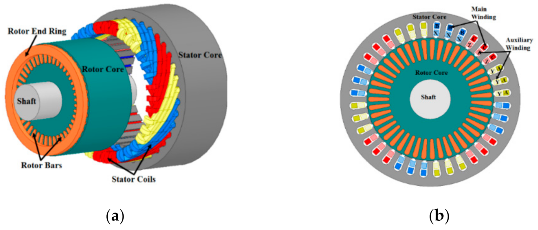
Both windings were designed with the same number of turns per phase but with distinct conductor sizes. The auxiliary winding features a thinner wire size and higher DC resistance than the main winding. The specifications and ratings of the unoptimized SCIM with auxiliary stator winding are given in Table 1, while Figure 1 shows an exploded 3D view of the primary components and 2D representation of the three-phase SCIM with auxiliary winding.
Table 1.
Specifications and ratings of the unoptimized motor.
Figure 1.
Configuration of the three-phase SCIM with auxiliary winding: (a) exploded 3D view; (b) 2D representation.
3. Problem Definition
3.1. Stator Current
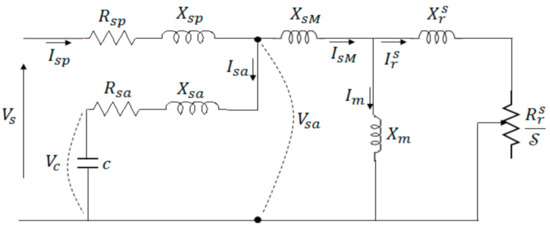
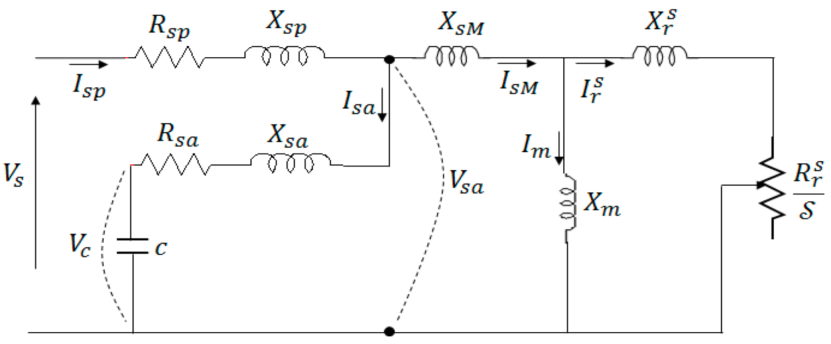
The principle of a three-phase SCIM with auxiliary winding can be analyzed by an equivalent per-phase steady-state circuit, as illustrated in Figure 2 [11]. The machine can be modeled by two branches, with each branch possessing its own independent resistance and leakage reactance , respectively. There is a common mutual reactance that occurs as a result of the two sets of windings housed in the same slots, which are hence coupled by their leakage flux [11].
Figure 2.
An equivalent per-phase steady-state circuit of an induction motor with auxiliary winding.
In the figure, and denote the rotor leakage reactance and resistance, respectively, and referred to the stator; and denote the auxiliary stator winding resistance and leakage reactance, respectively; denotes the magnetizing reactance; denotes the slip; denotes the supply voltage; denotes the voltage across the capacitor ; denotes the voltage across the RLC branch that represents the auxiliary winding; denotes the magnetizing current; denotes the rotor current referred to the stator; denotes the current flowing through the mutual reactance; denotes the current flowing through the capacitive auxiliary winding; and denotes main (primary) stator current. Neglecting the core loss resistance, the magnetizing branch represented by the magnetizing reactance can be written as in Equation (1) [30,31].
From Equation (1), denotes the stator number of turns in series per phase; denotes the fundamental winding factor; denotes the fundamental angular frequency of phase current; denotes the air gap length; denotes the fundamental number of pole pairs; denotes the permeability of the free space; denotes the pole pitch; denotes the effective stator stack length; denotes the Carter’s coefficient value; and denotes the magnetic saturation factor. The subscripts and denote the parameters of the primary (main) and auxiliary windings, respectively. Additionally, the subscripts and denote the parameters of the stator and rotor, respectively, while the superscript denotes quantities as referred to the stator. With no capacitor connected to the auxiliary winding, the current in the auxiliary winding is zero. Its flux linkage is also zero, and therefore the mutual reactance between the main and auxiliary windings is inexistant. The unloaded current is totally magnetizing. In this case, the magnetizing reactance is only dependent on the inverse air gap length as defined in Equation (1). The larger the air gap length, the lower the magnetizing reactance and the greater the magnetizing current would be. When the unloaded current increases, the magnetic saturation factor increases, and as such the magnetizing reactance decreases. Both the air gap length and saturation factor influence the magnetizing reactance. An increase in the unloaded current results in a poorer power factor. Once a set of capacitors is connected to the auxiliary winding, an excitation current will flow through it. In this case, there is a flux linkage associated with the auxiliary winding. A common mutual reactance occurs due to the mutual coupling of the main and auxiliary windings with the non-air-gapped flux components (leakage flux) [11]. From the equivalent steady-state circuit in Figure 2, the unloaded current is decomposed into two separate components, namely and . The stator current is given as in Equation (2), while the first component of the unloaded current is expressed as in Equation (3), which is the current flowing through the capacitive auxiliary winding.
The current, , which is flowing into the mutual reactance also has two components, namely the magnetizing current, , and the rotor current referred to the stator, , also known as the load component of the stator current. The total current in the magnetizing branch and rotor circuit is given by Equation (4). Using Equation (1), the magnetizing current flowing into the magnetizing branch is expressed as in Equation (5).
The unloaded current of a three-phase SCIM with capacitive auxiliary winding can be expressed as in Equation (6). With the supply voltage kept constant, the magnetizing current would remain constant for a fixed air gap length and fixed auxiliary winding capacitance value. The stator current in Equation (7) will vary only as a function of its load component.
where is the unloaded current of the three-phase SCIM without capacitive auxiliary winding. From Equation (6), the air gap length and capacitive reactance influence the unloaded current. Increasing the air gap length will result in an increase in the magnetic saturation factor, thus decreasing the magnetizing reactance, and consequently increasing the unloaded and magnetizing currents. This will result in a reduction of the power factor. To enhance the power factor, capacitors with suitable capacitance should be connected to the auxiliary winding. The presence of capacitors in the auxiliary winding will decrease the unloaded and magnetizing currents, thus improving the power factor.
3.2. Electromagnetic Torque per Ampere
A steady-state electromagnetic torque equation may be obtained for a rotor voltage of zero, i.e., when a rotor is short-circuited. The general electromagnetic torque expression is given in Equation (8) [30,31] and the torque per ampere is defined as in Equation (9). The ratio in Equation (9) provides the relationship between the unloaded and loaded conditions for a three-phase SCIM. With the capacitors existing in the auxiliary winding circuit while keeping the air gap length constant, the torque varies as a function of the rotor current. Moreover, the stator current depends on the ratio .
As previously stated, the presence of capacitors in the auxiliary winding decreases the unloaded current. The stator current decreases while developing the same amount of torque as when the capacitors were not connected. The reduction in stator current to produce the same amount of torque required by the induction motor is limited in the form of . The air gap length also influences the unloaded and magnetizing currents. This influence is due to the magnetic saturation factor, which changes as a function of air gap length. The main role of the variation of the air gap is to control the magnetizing reactance, which has an impact on the magnetizing current. A very large air gap will reduce the torque and power factor; however, with the presence of capacitors in the auxiliary winding circuit, the motor’s magnetizing capability may be compensated, where the motor does not need to draw an increased magnetizing current from the power grid to develop the same amount of torque. The negative effect of a larger air gap length has been mitigated by the introduction of capacitors into the auxiliary winding circuit. As such, the torque and power factor may be kept high with a large air gap and capacitors connected to the auxiliary winding.
4. Optimization Problem
4.1. Overview of the Design Optimization
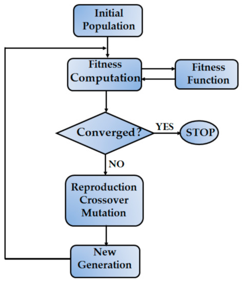
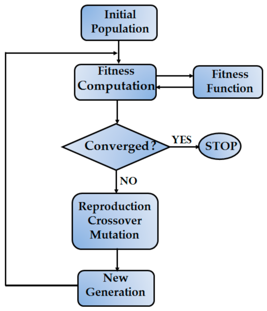
A GA starts with a random initial population of a string of variables that are analogous to a pool of chromosomes. Each iteration of the algorithm is called a generation. The objective function is generally referred to as the fitness function, which associates a unique real number called the fitness value with each chromosome. The few chromosomes that possess the best fitness values, called elite children, are directly passed on to the next generation [32]. Moreover, the algorithm simulates crossover and mutation, which are, respectively, binary and unary operations on the existing chromosomes, and this process produces new children for the next generation. The process is repeated until at least one stopping criterion is met [24,25,26,27]. The flow chart of the GA for the optimization design is shown in Figure 3 [17] and the main steps of the GA are given as follows [17,24,25,26,27,33]:
Figure 3.
Overview of the GA optimization process.
- Generate the first (initial) population randomly based on design parameters and an objective function;
- Perform selection through computation of the fitness functions;
- Perform the test convergence and stop if satisfied or else continue;
- Start the reproduction process by applying the crossover and mutation genetic operators;
- A new generation has been produced. Repeat steps 2 to 5 until a suitable criterion is met.
4.2. Implementation of GA for Optimal Design
The optimization objective function here was the torque per ampere (TPA). There were two sets of populations in the GA, namely the air gap length, , and the excitation capacitance, . Both sets of populations had ten chromosomes each, which were randomly selected. The fitness values of the objective function for desired performance of the three-phase SCIM were set to 1 Nm/A for unloaded operation and 4.5 Nm/A for fully loaded operation. Using the Monte Carlo roulette selection method (MCRSM), the fitness values of the objective function were computed for each chromosome in the and populations. The chromosomes that had potential to produce high values in the fitness functions (values close to 1 Nm/A with no load and 4.5 Nm/A with a full load) had a chance of being selected were consequently allowed to survive in succeeding generations if selected. On the other hand, chromosomes that were not suitable to produce high fitness values were discarded. The expression used to compute the fitness probability of each chromosome is given as follows:
where denotes the fitness probability and denotes the fitness or objective function of the or chromosome in population or . The fundamental winding distribution factor, pole pitch, stack length, and Carter’s coefficient were constant design parameters in this optimization search. If the operational temperature, load, supply voltage, frequency, and speed are kept constant, the objective function may be given as follows:
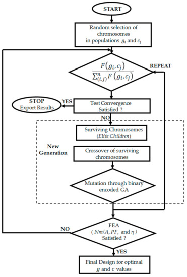
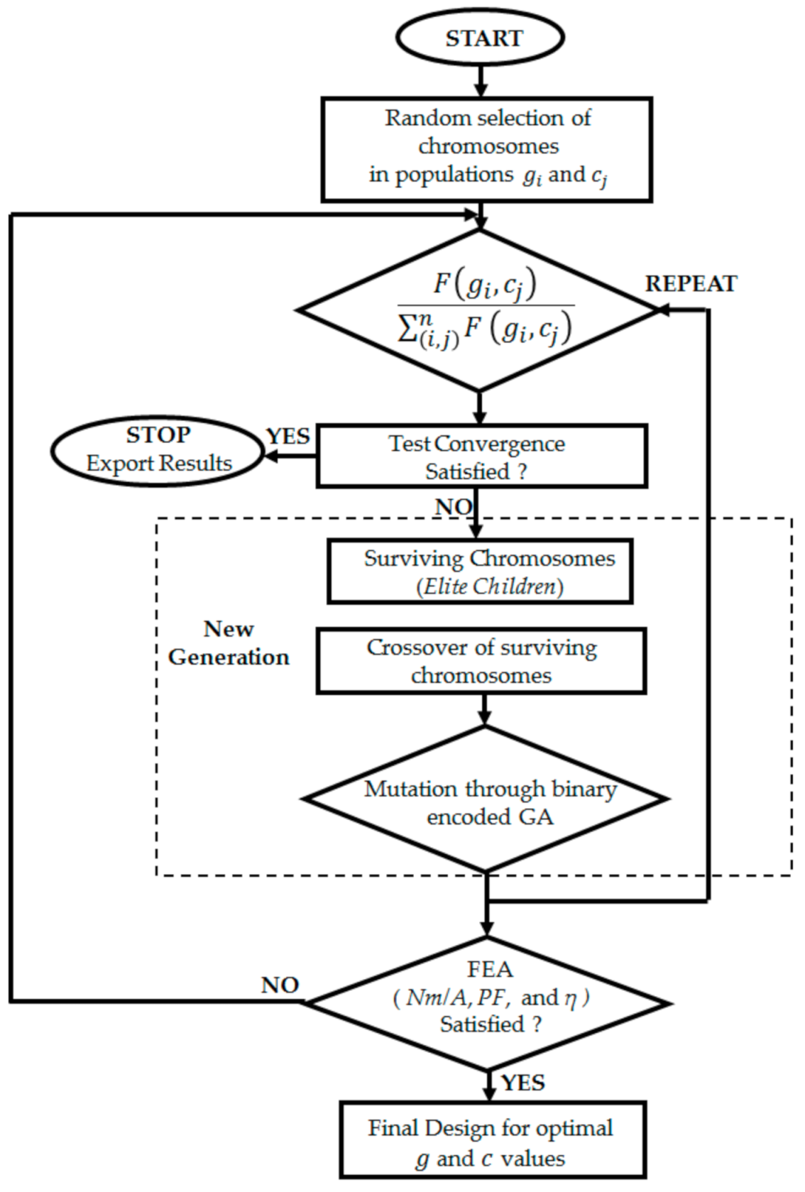
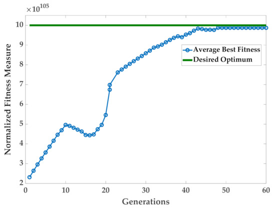
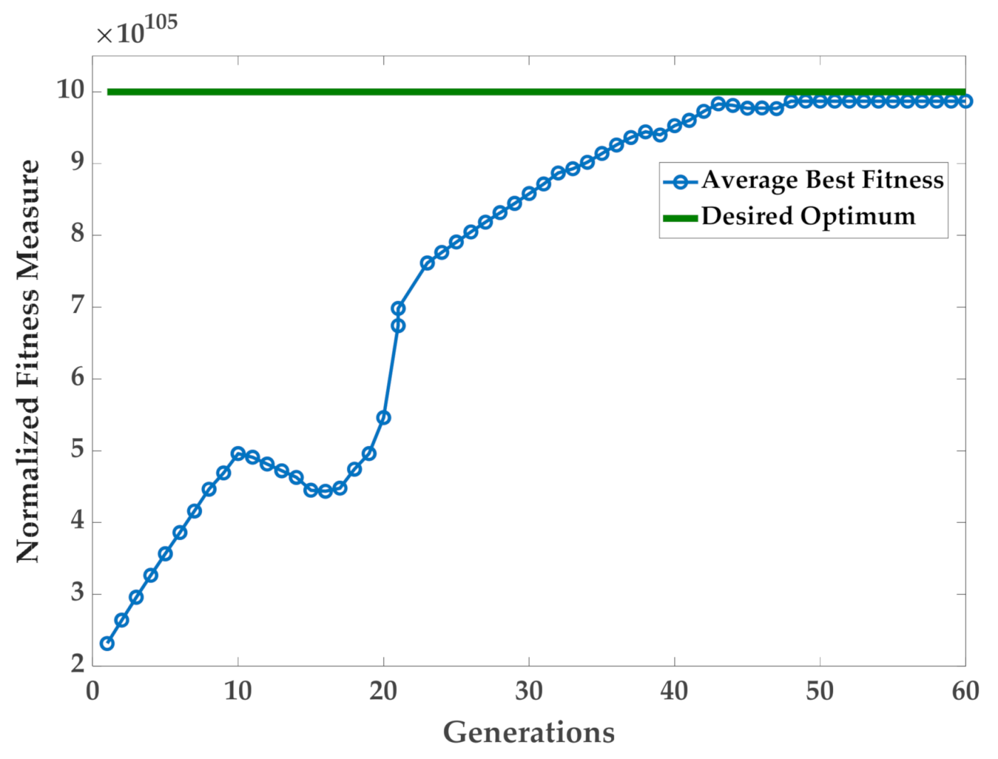
A flowchart that expresses the implementation of the design optimization by the GA is illustrated in Figure 4, and the GA convergence of the fitness measure is shown in Figure 5. Furthermore, Table 2 gives the chromosomes and their limits. In addition, Table 3 provides the values of the selected chromosomes. Successful chromosomes were used to perform crossover, such that they would be expressed in terms of their genes. The crossover point was selected between the first and the last bits of a chromosome. The chromosomes were converted into binary code and written in a matrix form with six rows and four columns. The probabilities of crossover and mutation were 0.85 and 0.045, respectively. For an initial population size of 10, many generations were needed in the GA for the population to converge to an optimum solution. The algorithm was executed 8 times over about 27 min on a computer with an Intel Xeon E5-1607 v3 CPU operating at 3.1 GHz with a 64-bit operating system and 32 GB of random-access memory. The search was halted after 60 generations were processed. As seen in Figure 5, average individuals throughout the generations with fitness measures near the desired optimum were selected.
Figure 4.
Flow chart of the design optimization process.
Figure 5.
Convergence of the fitness measure with the GA.
Table 2.
Chromosomes and their limits.
Table 3.
Selected chromosomes.
In order to find the final design for the optimal air gap length and optimal capacitive auxiliary stator winding, the design of the SCIM with auxiliary capacitive winding incorporated the constraint with , where the constraint functions, , in this optimization problem were to maximize the efficiency , power factor , and the torque per ampere , and the functions can be respectively defined by the following inequalities:
A constrained problem should be converted into an unconstrained problem by introducing penalty functions into the optimization model to restrict the violation of constraints. Under full load, the expected constraints for the torque per ampere, power factor, and efficiency were 3.2 Nm/A, 0.98 p.u, and 84%, respectively. Using constraint violation, an augmented objective function F(x) can be expressed as follows:
where denotes the penalty coefficient. From the constraint functions, depends on the iron and stator copper losses. The iron loss is reduced by increasing the air gap length and is limited by the optimal capacitor’s value in the auxiliary circuit. Constraint depends on the magnetizing reactance, which is greatly influenced by the air gap length and the auxiliary circuit capacitor’s value. Furthermore, depends on the air gap length and the magnetizing current. The reduction in stator current to produce the same amount of torque required by the induction motor is limited in the form of . For a constant load, is constant and varies as a function of the air gap length and auxiliary excitation current. Looking at the problem as defined in Equations (6) and (11), the rotor’s outer diameter and number of turns per phase for the main and auxiliary windings constitute the key design variables that are involved in finding a solution to the optimization problem. The design variables and their limits are given in Table 4, while Table 5 provides the optimized design parameters.
Table 4.
Design variables and their limits.
Table 5.
Optimized design parameters.
5. Finite Element Analysis
FEA was used to verify the accuracy of the GA presented in the previous section. The air gap length variation involves the alteration of the squirrel cage rotor’s outer diameter while keeping the stator’s bore diameter constant. The design input parameters are thus the rotor’s outer diameter, the number of turns per phase for the main and auxiliary windings, and the auxiliary circuit capacitor’s value. A sequential nonlinear programing optimization algorithm was applied for the enhancement of the TPA.
5.1. Flux Density Distribution
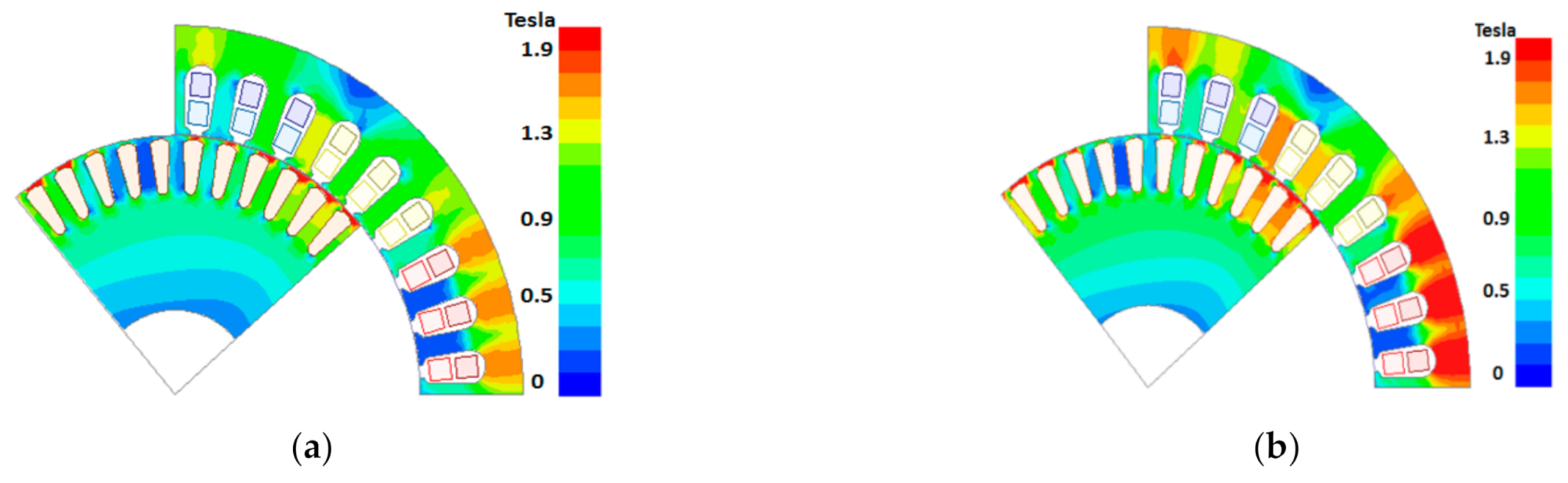
Two-dimensional (2D) FEA was performed using the ANSYS 16.0 electromagnetic package. The full-pitched three-phase main windings were excited by three-phase sinusoidal voltage. Skin effect and core loss were considered in the FEA for an AC transient magnetic solution [1]. Due to the symmetry of the motor, only pole pitch was considered in the FEA. Figure 6a,b shows the flux density distribution in the iron core of the SCIM with an optimal 0.488-mm air gap length for the phase capacitance values of 0 μF and 86 μF, respectively. The flux density distribution in Figure 6a,b lies in the plane of the model (x,y). The vector boundary condition with zero vector potential was set to the outer region of the machine’s model. The edges of the 2D Cartesian coordinate area were modeled with a master boundary condition on the x-axis and a slave boundary condition on the y-axis. In total, 2548 elements were obtained for the single-pole pitch geometry. An element length-based mesh operation was applied to the rotor core and stator core geometries with minimum edge lengths of 0.000438 mm and 0.000302 mm, respectively, and maximum edge lengths of 0.0085 mm and 0.00916 mm, respectively. Moreover, a surface approximation mesh operation is applied to the phase coil and rotor bar geometries with minimum edge lengths of 0.00296 mm and 0.00054 mm, respectively, and maximum edge lengths of 0.00699 mm and 0.00698 mm, respectively. The simulation stop time and time-step size used in the FEA were 0.02 s and 2 × 10⁻⁴ s, respectively. The simulation ran for about two hours on the computer described in Section 4.2 of this paper.
Figure 6.
Flux density distribution for g = 0.488 mm, (a) auxiliary winding with 0 μF, (b) auxiliary winding with 86 μF.
The introduction of capacitors into the auxiliary winding circuit increases the saturation level of the stator back iron, where the increase in the saturation level is proportional to the increase in the capacitor’s value. The main impact of the auxiliary capacitive winding is to compensate the exciting current needed by the motor to develop a high torque without drawing an increased lagging reactive current from the power network. An obvious increase in the saturation level may be easily noticed by an increase in the capacitor’s value. The effect of air gap length variation on magnetic saturation may not be as clearly noticeable as a change in capacitor values if presented in a form of flux density distribution in different iron parts of the SCIM; however, the effect of air gap length variation may be easily noticed by changes in critical machine parameters, such as the magnetizing reactance, as illustrated in the next subsection.
5.2. Motors Equivalent Parameters from FEA
The equivalent circuit parameters obtained from FEA for the SCIM without compensation and with compensation are presented in Table 6 and Table 7, respectively. The FEA results in Table 6 provide evidence that the magnetizing reactance decreases with an increase in the air gap length. On the other hand, Table 7 demonstrates that the presence of an 86-μF capacitor significantly increases the magnetizing reactance. The latter is slightly reduced when the air gap length is increased. The effect of the capacitor in the auxiliary winding is magnetizing, while the effect of the large air gap length is demagnetizing. Simply put, an increase in the air gap length without any capacitive compensation in the auxiliary winding would require the SCIM to more reactively draw power from the network in order to meet the same output performance. In contrast, with capacitive compensation through the auxiliary winding, the SCIM does not need to draw an increased magnetizing current from the power grid to produce the same amount of torque. The negative effect associated with a large air gap length has been mitigated by the presence of capacitors in the auxiliary winding here.
Table 6.
Parameters of the motor from the FEA with 0 μF.
Table 7.
Parameters of the motor from the FEA with .
Although the leakage reactance referred to the stator may be affected by magnetic saturation, the FEA results in both Table 6 and Table 7 show no significant change when the air gap length was varied. Although the skin effect was considered in the FEA, the rotor resistance referred to the stator did not exhibit any significant change because of the air gap length or the presence of capacitors in the auxiliary winding.
6. Practical Validation and Discussion of Results
6.1. Experimental Setup
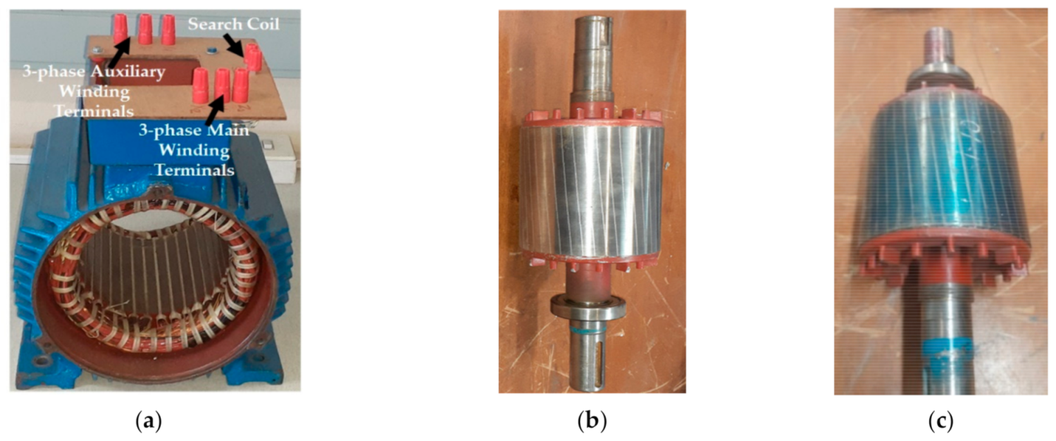
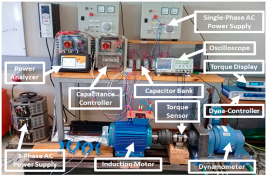
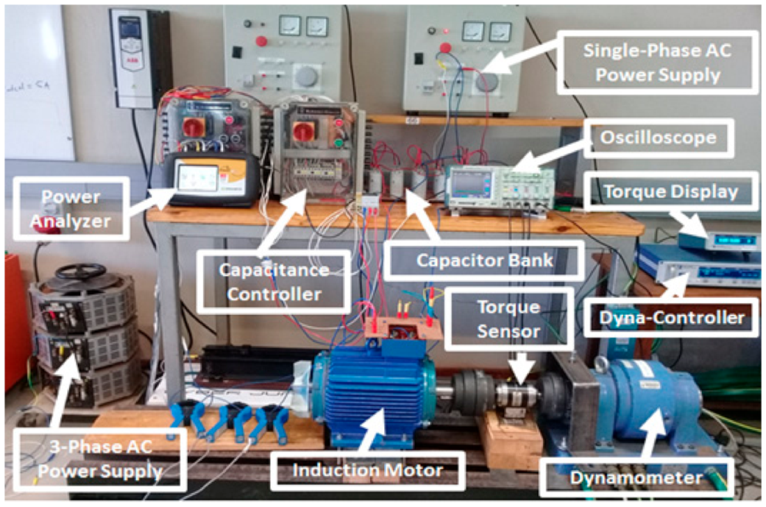
The experimental setting was comprised of a three-phase SCIM with auxiliary winding coupled to a model 1 PB 115 powder dynamometer with a water braking cooling system [1,2]. Figure 7 shows the photographs of the SCIM stator and optimized and unoptimized rotors, while Figure 8 shows a photo of the experimental setup.
Figure 7.
Main constituents of the SCIM with auxiliary winding: (a) stator; (b) optimized rotor; (c) unoptimized rotor.
Figure 8.
A photo of the experimental setup.
6.2. Induction Motors Equivalent Parameters
The primary (main) and auxiliary windings of the optimized SCIM had 48 turns per phase and their phase resistances were found to be 0.492 Ω and 1.61 Ω, respectively. It should be noted that the primary (main) and auxiliary windings of the unoptimized SCIMs had 54 turns per phase, and their phase resistances were found to be 0.555 Ω and 1.8 Ω, respectively. Unloaded and blocked rotor tests were used to obtain the magnetizing reactance and the leakage reactance referred to the stator windings, respectively. Table 8 compares the measured (MEA) parameters of the optimized and unoptimized SCIMs.
Table 8.
Parameters for optimized and unoptimized SCIMs.
6.3. Induction Motors Performance Evaluation
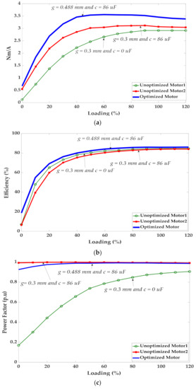
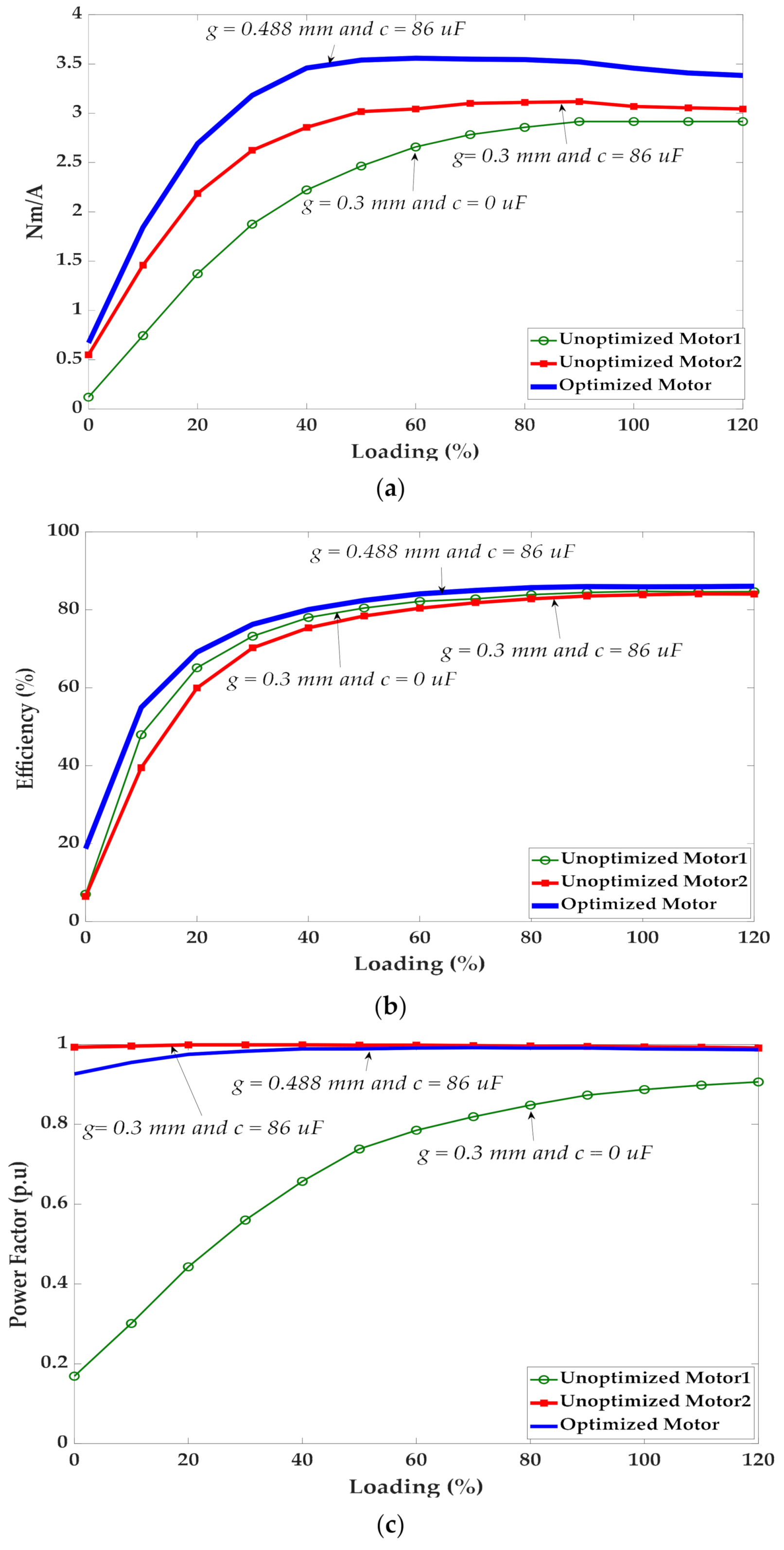
Figure 9a–c shows the measured TPA, efficiency, and power factor results. The efficiency was indirectly determined according to the IEC 60034-2-1 standard [34,35] with the standard 2-1-1B test method by the summation of separate losses at thirteen load points between unloaded and 120% load of the rated torque for a nominal frequency of 50 Hz. The additional load losses, , were measured starting from the residual losses, [35,36], which were determined for each load point by subtracting from the input power, , the output power, , the constant losses, , the rotor cage winding losses, , the stator primary winding losses, , and the stator auxiliary winding losses, [37]. The residual losses for the three-phase SCIM with auxiliary capacitive winding were determined using Equation (16):
Figure 9.
Comparison between unoptimized motors and a motor with an optimal air gap length and capacitor value: (a) torque per ampere vs. loading; (b) efficiency vs. loading; (c) power factor vs. loading.
The constant losses, which were obtained for various terminal voltages between and , were calculated using Equation (17) [37]:
where denotes the unloaded supply voltage; denotes the nominal voltage; denotes the core loss; and denotes the rotational loss. The latter mainly includes the bearing friction loss and windage loss. For normal-, small-, and medium-sized SCIMs, rotational loss is generally calculated using Equation (18) [38]:
The rotational loss, , was corrected for by considering the operating point via slip and is determined using Equation (19) [37]:
where denotes the corrected rotational loss operating at slip . To reduce the effects of measurement errors, the standard establishes a linear regression analysis of residual losses, expressed as a function of the square of load torque according to the relationship expressed in Equation (20) [36]:
where T denotes the torque measured in the variable load test; A denotes the slope of the line of best fit to the test points and B denotes the intercept at zero torque [34,35,36]. A and B are obtained by considering thirteen load points and using the relations in (21) and (22) respectively. The additional load losses for each of the load points can be determined by using (23) [34,35,36].
where denotes the number of load points. The electromagnetic power is transmitted to the rotor by the stator through the law of electromagnetic induction. Consequently, the rotor copper losses are calculated using Equation (24):
The total losses are calculated using Equation (25), and the efficiency at each of the load points is determined as in Equation (26):
Table 9 shows a comparison of the torque per ampere (TPA) as per the FEA and experimental results between the optimized and unoptimized SCIMs. TPA enhancement is based on the concept that necessitates the reduction of stator current to produce the same amount of torque required by the induction motor. The stator current was reduced here by exciting the auxiliary winding with a reactive current. Furthermore, a high auxiliary winding DC resistance contributes to additional stator copper losses , thus dropping the efficiency. To address the problem, the concept of a large air gap was introduced in order to decrease the iron losses and improve the efficiency. A large air gap decreases the torque and the power factor. An optimal air gap length (OAL) and capacitive auxiliary stator winding (OCASW) configuration is required to obtain an enhanced TPA without compromising the power factor and efficiency. From the GA results, the OAL was 0.488 mm and the optimal capacitance value was 86 μF. The experimental results shown in Figure 9a–c provide a comparison between the optimized motor ( and ), unoptimized motor 1 ( and ), and unoptimized motor 2 ( and ). The results in Figure 9a provide evidence that the TPA was significantly enhanced with an OAL of 0.488 mm and optimal capacitance value of 86 μF. Unoptimized motor 2 produced a high TPA when compared to unoptimized motor 1; however, the experimental results in Figure 9b show that unoptimized motor 2 experienced a slight drop in efficiency when a capacitor with a capacitance value of 86 μF was connected to the auxiliary winding. The drop in efficiency was due to copper losses in the auxiliary winding and a slight increase in iron loss.
Table 9.
Comparison of torque per ampere between the FEA and MEA results.
With an optimal air gap of 0.448 mm (optimized motor), the increase in iron loss due to the presence of the 86 μF capacitor in the auxiliary winding was mitigated, thus maintaining high efficiency as seen in Figure 9b. Table 10 compares the additional load losses, , the rotor copper losses, , the corrected rotational losses, , the iron losses, , the copper losses in the primary winding, , the copper losses in the auxiliary winding, , and the efficiency, , of all three motors at a nominal torque operating point. The optimized motor, unoptimized motor 1, and unoptimized motor 2 obtained full load efficiency values of 84.74%, 83.85%, and 85.87%, respectively. The optimal capacitance value of 86 μF enhanced the power factor in both unoptimized motor 2 and the optimized motor as demonstrated in Figure 9c. The improvement of the power factor was more significant for unoptimized motor 2 than the optimized motor when operating below 40% of the full load.
Table 10.
Comparison of input power, losses, and efficiency at the nominal torque operating point.
After modification of the stator winding from a single to dual configuration, slot filling factors of 33.08% and 9.33% were achieved for the main and auxiliary windings, respectively. There was a 50% drop in the slot filling factor as compared to the original SCIM. As a result, the iron losses in all three machines were high, as noted in Table 10, and they approximately contributed to 38%, 40%, and 29% of the total losses, respectively. The typical iron loss share in conventional SCIMs is estimated to be 20% of the total loss on average [39]. With the absence of the auxiliary winding, the increase in the slot area caused an increase in flux density around the slot, thus increasing iron loss. To address this problem, maximization of slot filling factor may be required through design optimization in cases where the stator winding of a conventional SCIM is modified from a single to dual configuration. On the other hand, the modification of the stator winding configuration to fit both main and auxiliary windings in the same slot may not be required when designing a SCIM with a dual stator winding configuration from scratch.
7. Conclusions
This paper has presented a genetic algorithm optimization method assisted by finite element analysis to obtain optimal air gap length and capacitive auxiliary stator winding values for three-phase squirrel induction machines. Although the sensitivity analysis in the finite element model showed great results for the torque per ampere, efficiency, and power factor when the air gap length and capacitance auxiliary winding varied, only a single objective function was defined in the genetic algorithm model presented in this paper instead of a multi-objective function. The use of a single objective function rather than a multi-objective function has simplified the complexity associated with a multi-objective function in a genetic algorithm optimization model. The optimal values of the air gap length and capacitive auxiliary stator winding were achieved owing to the penalty functions related to the objective and constraint functions introduced in the genetic algorithm model. The use of binary code rather than the original values of the air gap length and auxiliary capacitance values, and the avoidance of a derivative function, made the genetic algorithm a good fit for the optimization problem solved in this paper. Experimental measurements were taken for the optimized and unoptimized motors to validate the results obtained from numerical computation. The numerical and experimental results demonstrate a high degree of corroboration here. The presented results show evidence that the optimized motor can achieve high torque per ampere values through different loading conditions when compared to unoptimized motors without compromising the merit of achieving an excellent power factor and high efficiency.
Although the genetic algorithm optimization model presented in this paper has provided good results, the algorithm was executed eight times over about 27 min, consequently processing 60 generations. This speed of computation may be excessive in environments that require fast design optimization. The long processing period can still be reduced by either revising the criteria pertaining to the constraint functions or redefining the objective function and the convergence stop criteria. The use of other evolution-based optimization methods used for the design of electrical machines can still be contemplated.
Funding
This research received no external funding.
Institutional Review Board Statement
Not applicable.
Informed Consent Statement
Not applicable.
Data Availability Statement
Not applicable.
Conflicts of Interest
The author declares no conflict of interests.
References
- Muteba, M.; Nicolae, D.M. Torque per Ampere Enhancement of a Three-Phase Induction Motor by Means of a Capacitive Auxiliary Winding. In Proceedings of the IEEE Transportation and Electrification Conference and Expo, Long Beach, CA, USA, 13–15 June 2018. [Google Scholar]
- Muteba, M.; Nicolae, D.M. Influence of Air-Gap Length on the Performance of a Three-phase Induction Motor with a Capacitive Auxiliary Stator Winding. In Proceedings of the 44th Annual Conference of the IEEE Industrial Electronics Society, Washington, DC, USA, 21–23 October 2018. [Google Scholar]
- Muteba, M.; Nicolae, D.M. Effect of capacitive auxilary winding on a three-phase induction motor performance behaviour. In Proceedings of the IEEE African Conference, Cape Town, South Africa, 18–20 September 2017. [Google Scholar]
- Jimoh, A.A.; Nicolae, D.V. A study of improving the power factor of a three-phase induction motor using a static switched capacitor. In Proceedings of the 12th International Power Electronics and Motion Control Conference, Portoroz, Slovenia, 30 August–1 September 2006. [Google Scholar]
- Jimoh, A.A.; Nicolae, D.V. Controlled Capacitance Injection into a Three-Phase Induction Motor through a Single-Phase Auxiliary Stator Windin. In Proceedings of the IEEE Power Electronics Specialists Conference, Orlando, FL, USA, 17–21 June 2007. [Google Scholar]
- Muteba, M.; Jimoh, A.A.; Nicolae, D.M. Improving Three-Phase Induction Machines Power Factor Using Single Phase Auxiliary Winding Fed by an Active Power Filter. In Proceedings of the IEEE African Conference, Windoek, Namibia, 26–28 September 2007. [Google Scholar]
- Jimoh, A.A.; Nicolae, D.V. A Three-Phase Induction Motor with Power Electronic Controlled Single-Phase Auxiliary Stator Winding. In Proceedings of the IEEE International Electric Machines and Drives, Antalya, Turkey, 3–5 May 2007. [Google Scholar]
- Lattemer, T.A.; Novotny, D.W.; Lipo, T.A. Single-Phase Induction Motor with an Electronically Controlled Capacitor. IEEE Trans. Ind. Appl. 1991, 27, 38–43. [Google Scholar]
- Bianchi, N.; Bolognani, S.; Tonel, F. Thermal Analysis of a Run-Capacitor Single-Phase Induction Motor. IEEE Trans. Ind. Appl. 2003, 39, 457–465. [Google Scholar] [CrossRef]
- Tamrakan, I.M.; Malik, O.P. Power Factor Correction of Induction motors Using PWM Inverter Fed Auxiliary Stator Winding. IEEE Trans. Energ. Conv. 1999, 14, 426–432. [Google Scholar] [CrossRef]
- Muljadi, E.; Lipo, T.A.; Novotny, D.W. Power Factor Enhancement of Induction Machines by Means of Solid State Excitation. IEEE Trans. Pow. Electr. 1989, 4, 409–418. [Google Scholar] [CrossRef]
- Appelbaum, J.; Fuchs, E.F.; White, J.C. Optimization of Three-Phase Induction Motor Design Part I: Formulation of the Optimization Technique. IEEE Trans. Energ. Conv. 1987, 2, 407–414. [Google Scholar] [CrossRef]
- Lei, G.; Zhu, J.; Guo, Y.; Liu, C.; Ma, B. A Review of Design Optimization Methods for Electrical Machines. Energies 2017, 10, 1962. [Google Scholar] [CrossRef] [Green Version]
- Duan, Y.; Ionel, D.M. A Review of Recent Developments in Electrical Machine Design Optimization Methods with a Permanent-Magnet Synchronous Motor Benchmark Study. IEEE Trans. Ind. Appl. 2013, 49, 1268–1275. [Google Scholar] [CrossRef]
- Boules, N. Design optimization of permanent magnet dc motors. IEEE Trans. Ind. Appl. 1990, 26, 786–792. [Google Scholar] [CrossRef]
- Kwon, S.; Park, S.; Lee, J. Optimum design criteria based on the rated watt of a synchronous reluctance motor using a coupled FEM and SUMT. IEEE Trans. Magn. 2005, 41, 3970–3972. [Google Scholar] [CrossRef]
- Uler, G.F.; Mohammed, O.A.; Chang-Seop, K. Design optimization of electrical machines using genetic algorithms. IEEE Trans. Magn. 1995, 31, 2008–2011. [Google Scholar] [CrossRef]
- Yazdani-Asrami, M.; Gorjikolaie, M.T.; Gholamian, S.A. Comparison of Several Improved Versions of Particle Swarm Optimizer Algorithm for Parameter Estimation of Squirrel-Cage Induction Motors. J. Intelek 2014, 8, 27–35. [Google Scholar]
- Wang, W.; Zhao, J.; Zhou, Y.; Dong, F. New Optimization Design Method for a Double Secondary Linear Motor Based on R-DNN Modeling Method and MCS Optimization Algorithm. Chin. J. Electr. Eng. 2020, 6, 98–105. [Google Scholar] [CrossRef]
- Bertsimas, D.; Tsitsiklis, J. Simulated annealing. Stat. Sci. 1993, 8, 10–15. [Google Scholar] [CrossRef]
- Passino, K.M. Biomimicry of bacterial foraging for distributed optimization and control. IEEE Control Syst. Mag. 2002, 22, 52–67. [Google Scholar]
- Mishra, Y.; Mishra, S.; Tripathy, M.; Senroy, N.; Dong, Z. Improving stability of a DFIG-based wind power system with tuned damping controller. IEEE Trans. Energy Convers. 2009, 24, 650–660. [Google Scholar] [CrossRef]
- Coelho, L.D.S.; Silveira, O.D.C.; Sierakowski, C.; Alotto, P. Improved bacterial foraging strategy applied to TEAM workshop benchmark problem. IEEE Trans. Magn. 2010, 46, 2903–2906. [Google Scholar] [CrossRef]
- Mallik, S.; Mallik, K.; Barman, A.; Maiti, D.; Biswas, S.K.; Deb, N.K.; Basu, S. Efficiency and Cost Optimized Design of an Induction Motor Using Genetic Algorithm. IEEE Trans. Ind. Elect. 2007, 64, 9854–9863. [Google Scholar] [CrossRef]
- Zhao, J.; Zhang, W.; Fang, J.; Yang, Z.; Zheng, L.Y. Design of HTS Linear Induction Motor Using GA and the Finite Element Method. In Proceedings of the 5th IEEE Conference on Industrial Electronics and Applications, Taichung, Taiwan, 15–17 June 2010. [Google Scholar]
- Rao, K.S.R.; Othman, A.H.B. Design optimization of a BLDC motor by genetic algorithm and simulated annealing. In Proceedings of the International Conference on Intelligent and Advanced Systems, Kuala Lumpur, Malaysia, 25–28 November 2007. [Google Scholar]
- Etemadi, M.; Haghighian, R. Design Optimization of Wound Rotor Induction Motor Using Genetic Algorithm. In Proceedings of the 5th Conference on Knowledge-Based Engineering and Innovation, Tehran, Iran, 28 February–1 March 2019. [Google Scholar]
- El-Ghany, H.A.A. Optimal PMU allocation for high-sensitivity wide area backup protection scheme of transmission lines. Electr. Power Syst. Res. 2020, 187, 106485. [Google Scholar] [CrossRef]
- Elgebaly, A.E.; Taha, I.B.M.; Azmy, A.M.; El-Ghany, H.A.A. Optimal Design and Control of SSSCs for TLs Considering Technical and Economic Indices Using GA and SAMPE-JAYA Algorithm. IEEE Access 2021, 9, 38907–38919. [Google Scholar] [CrossRef]
- Boldea, I.; Nasar, S.A. The Induction Machine Handbook; CRC Press: New York, NY, USA, 2002. [Google Scholar]
- Boldea, I.; Tutelea, L. Electric Machines: Steady State, Transients, and Design with Matlab; CRC: Boca Raton, FL, USA; Taylor & Francis: Abingdon, UK, 2010. [Google Scholar]
- Wang, Y.; Yi, X.; Wang, Y.; Zhang, X. Partial Discharge Investigation of Form-Wound Electric Machine Winding for Electric Aircraft Propulsion. IEEE. Trans. Transp. Elec. 2021, 7, 78–90. [Google Scholar] [CrossRef]
- Zhao, X.; Sun, Z.; Xu, Y. Multi-Objective Optimization Design of Permanent Magnet Synchronous Motor Based on Genetic Algorithm. In Proceedings of the 2nd International Conference on Machine Learning, Big Data and Business Intelligence, Taiyuan, China, 23–25 October 2020. [Google Scholar]
- IEC 60034-2-1: 2014, Rotating Electrical Machines—Part 2-1: Standard Methods for Determining Losses and Efficiency from Tests; IEC: Geneva, Switzerland, 2014.
- Rivera, R.I.; Tálaga, J.C.; Castrillón, R.M.; Quispe, E.C. Implementation of a Procedure to Determine Induction Motor Efficiency According to the IEC 60034-2-1 Standard. In Proceedings of the IEEE ANDESCON, Santiago de Cali, Colombia, 22–24 August 2018. [Google Scholar]
- Bucci, G.; Ciancetta, F.; Edoardo Fiorucci, E.; Simone, M.; Segreto, M.A. The Measurement of Additional Losses in Induction Motors: Discussion about the Actually Achievable Uncertainty. Energies 2020, 13, 78. [Google Scholar] [CrossRef] [Green Version]
- Richard Steckel, R.; Daum, S. Efficiency Analysis of Three-Phase and Dual Three-Phase Induction Machine with Sinusoidal Supply. In Proceedings of the IEEE International Electric Machines & Drives Conference, San Diego, CA, USA, 12–15 May 2019. [Google Scholar]
- Xiaobo, S.; Dawei, M.; Xiaoni, Y. Influence of impeller’s torque ripple on motor loss and efficiency of contra–rotating axial–flow fan. Electr. Mach. Control 2018, 22, 40–47. [Google Scholar]
- De Almeida, A.T.; Ferreira, F.J.T.E.; Baoming, G. Beyond Induction Motors—Technology Trends to Move up Efficiency. IEEE Trans. Ind. Appl. 2014, 50, 1268–1275. [Google Scholar] [CrossRef]


Publisher’s Note: MDPI stays neutral with regard to jurisdictional claims in published maps and institutional affiliations. |
© 2021 by the author. Licensee MDPI, Basel, Switzerland. This article is an open access article distributed under the terms and conditions of the Creative Commons Attribution (CC BY) license (https://creativecommons.org/licenses/by/4.0/).