Article

Effects of Bent Outlet on Characteristics of a Fluidic Oscillator with and without External Flow

Department of Mechanical Engineering, Inha University, 100 Inha-ro, Michuhol-gu, Incheon 22212, Korea
*
Author to whom correspondence should be addressed.
Energies 2021, 14(14), 4342; https://doi.org/10.3390/en14144342
Submission received: 23 June 2021 / Revised: 13 July 2021 / Accepted: 16 July 2021 / Published: 19 July 2021
(This article belongs to the Special Issue Numerical Heat Transfer and Fluid Flow 2021)

Abstract

:
A fluidic oscillator with a bent outlet nozzle was investigated to find the effects of the bending angle on the characteristics of the oscillator with and without external flow. Unsteady aerodynamic analyses were performed on the internal flow of the oscillator with two feedback channels and the interaction between oscillator jets and external flow on a NACA0015 airfoil. The analyses were performed using three-dimensional unsteady Reynolds-averaged Navier-Stokes equations with a shear stress transport turbulence model. The bending angle was tested in a range of 0–40°. The results suggest that the jet frequency increases with the bending angle for high mass flow rates, but at a bending angle of 40°, the oscillation of the jet disappears. The pressure drop through the oscillator increases with the bending angle for positive bending angles. The external flow generally suppresses the jet oscillation, and the effect of external flow on the frequency increases as the bending angle increases. The effect of external flow on the peak velocity ratio at the exit is dominant in the cases where the jet oscillation disappears.

1. Introduction

A fluidic oscillator has no moving parts and has the feature of creating a vibrating jet when a certain pressure is applied to the inlet. This characteristic is due to the specific geometry of the fluidic oscillator. The flow introduced into a fluidic oscillator flows along one wall of the mixing chamber due to the Coanda effect, forming a main stream. Part of this main stream goes to the outlet, and the other part flows into the feedback channels and returns to the inlet, changing the direction of the main stream to create a vibrating jet. A fluidic oscillator may or may not have one or two feedback channels, but in most cases, it has two feedback channels [1,2]. The jet frequency is determined according to the pressure applied to the oscillator inlet [3].
Fluidic oscillators have been applied and studied in various fields due to their advantages, such as robustness and simplicity. Raman [4] evaluated the effectiveness for cavity tone suppression when using a fluidic oscillator in fluid machinery through experiments. The fluidic oscillator was also effective in aeroacoustic control. The effect of a fluidic oscillator on turbine cooling is also recognized and actively studied. Hossain et al. [5] proved fluidic oscillators to be effective for film cooling. Wu et al. [6] evaluated the heat transfer using fluidic oscillators with large eddy simulation (LES) and unsteady Reynolds-averaged Navier-Stokes (URANS) analysis. They showed that the oscillating jets improved heat removal. In addition, various studies have been conducted to apply fluidic oscillators to wind turbines, flowmeters, commercial airplanes, etc. [7,8,9,10].
Recently, many studies have been conducted on the flow separation that occurs on airfoil [11,12,13]. In particular, it has been found to be effective to install an array of fluidic oscillators for controlling the flow separation on the wing of an aircraft or blade of a fluid machine [14,15]. Koklu and Owens [16] experimentally compared various flow control methods for flow on a ramp and confirmed that the fluidic oscillators were most effective in reducing the flow separation. Jones et al. [17] studied the flow separation control on a high-lift wing. Under the same conditions, fluidic oscillators showed similar lift performance with only 54% less mass flow rate compared with steady jet actuators. Melton et al. [18] evaluated the aerodynamic performance of a NACA0015 airfoil equipped with a simple-hinged flap and fluidic oscillators for flap angles in a range of 20° to 60°. Seele et al. [19] applied fluidic oscillators to the trailing edge of a vertical stabilizer of a commercial aircraft, improving its efficiency by about 50%.
In order to maximize the aerodynamic performance of airfoils using fluidic oscillators, many studies have been conducted on the effect of the mounting conditions of the oscillators on the performance. Koklu [20] experimentally examined two installation positions upstream of the flow separation point in an adverse-pressure-gradient ramp model. Fluidic oscillators installed closer to the separation point exhibited higher pressure recovery. Kim and Kim [21] experimentally studied various mounting conditions (arrangement, installation angles, etc.) of fluidic oscillators on a hump surface and showed that the mounting pitch angle of fluidic oscillators had the most sensitive effect on the flow control. Further, through a numerical analysis, Kim and Kim [22] showed that when fluidic oscillators were installed downstream of the separation point on an airfoil, their effect of increasing lift was excellent. The mounting position with the greatest lift depended on the angle of attack. Drag was reduced the most when the oscillators were mounted close to the leading edge for all angles of attack.
There has also been much research on the influence of the internal shape of fluidic oscillators on the flow control performance. Melton and Koklu [23] evaluated two fluidic oscillators with different exit-orifice sizes (1 mm × 2 mm and 2 mm × 4 mm). The larger oscillator size required larger mass flow rate but less power. Additionally, the separation control performance was better in the case of the larger model. Melton et al. [24] proposed a novel shape of fluidic oscillators by evaluating the performance of three types of fluidic oscillators with the same orifice size. Ostermann et al. [25] measured the pressure required to inject the same mass flow rate when the edges of fluidic oscillators were straight and curved. When the edges were curved, the same mass flow was provided with 20% lower pressure.
In addition to experiments on fluidic oscillators, numerical studies were also widely performed. Jeong and Kim [26] evaluated the peak outlet velocity ratio and pressure drop of a fluidic oscillator using URANS analysis in an investigation of the effect of the distance between the inlet nozzle and splitter on the performance. They also performed a multi-objective optimization of the oscillator. Pandey and Kim [27,28] conducted a numerical analysis of the flow in a fluidic oscillator using LES and URANS. They suggested that URANS analysis using an SST model more accurately predicted the internal flow of the fluidic oscillator than LES using the WALE model. Further, based on their analysis results, it was reported that the chamber width of the fluidic oscillator had a great influence on the flow velocity in the feedback channels.
Kim and Kim [29] investigated the flow control performance of fluidic oscillators on a NACA 0015 airfoil with a flap. They tested the effect of the pitch angle of oscillators installed just upstream of the flap on the aerodynamic performance for different flap angles. A pitch angle closer to the flap angle showed a better lift coefficient. However, due to the geometric limitations, pitch angles close to the flap angle could be achieved only by bending the outlets of the oscillators. They showed that the fluidic oscillators with a bent outlet nozzle successfully enhanced the aerodynamic performance of the airfoil, but they have not explained how the characteristics and performance (such as the oscillating jet frequency, peak velocity ratio, etc.) of the fluidic oscillator were changed by bending the outlet nozzle.
In practical applications of fluidic oscillators, especially flow control on airfoils, there may be a need for bending of the outlet nozzle to overcome geometric limitations, as in the work of Kim and Kim [29]. However, there have not been any investigations on the fluidic oscillator with a bent outlet nozzle. Thus, in the present work, the effects of a bent outlet nozzle on the performance of a fluidic oscillator with two feedback channels were investigated using URANS analysis. First, the effects of the bending angle of the outlet nozzle on the performance, such as oscillating jet frequency, peak velocity ratio, and pressure drop, were evaluated at different mass flow rates for a single fluidic oscillator without external flow. The bent fluidic oscillator was also tested for external flow over a NACA0015 airfoil with a simple hinge flap. The goal was to find how the characteristics of the fluidic oscillator change in the application to the flow control over the airfoil compared to the case without external flow.

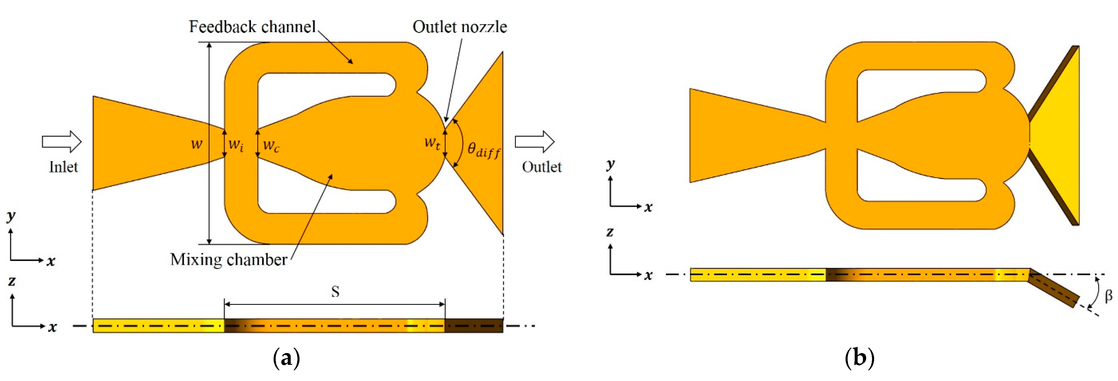
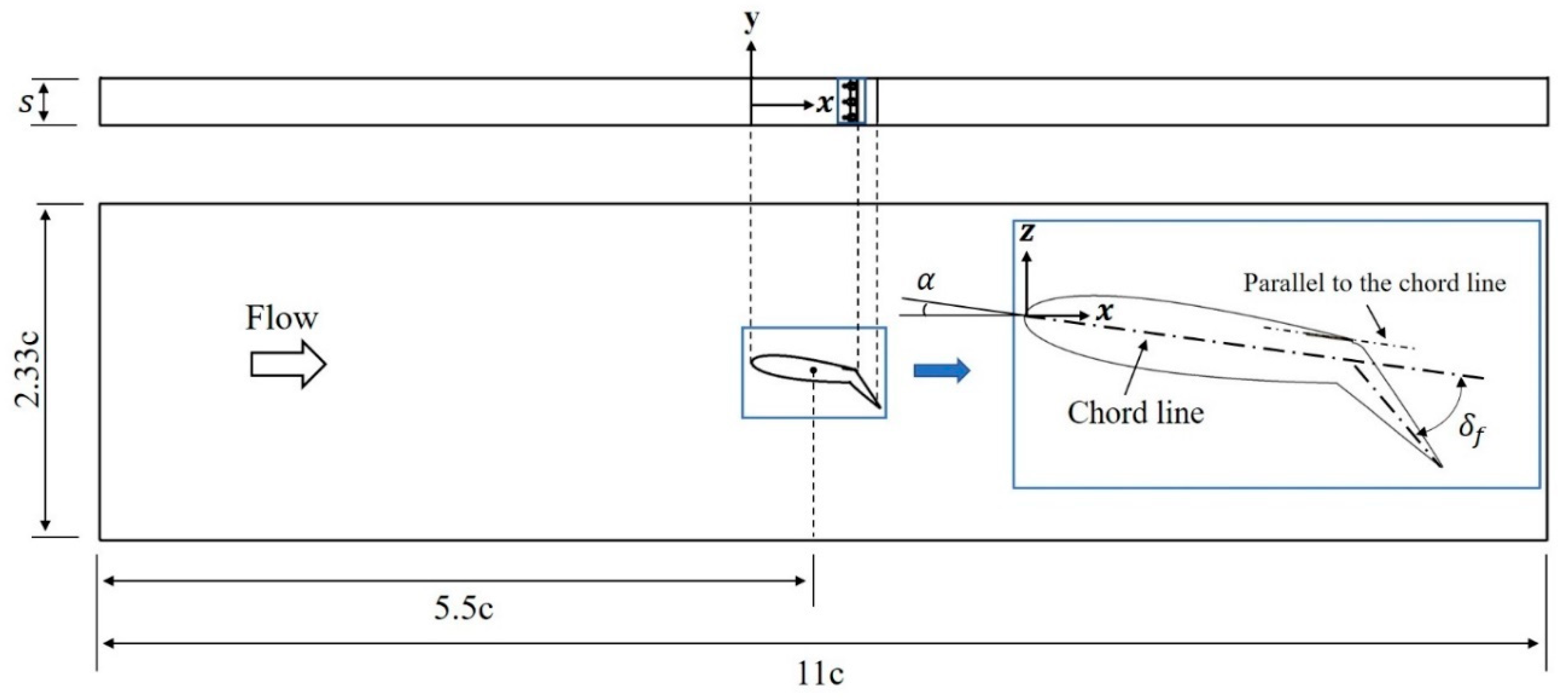
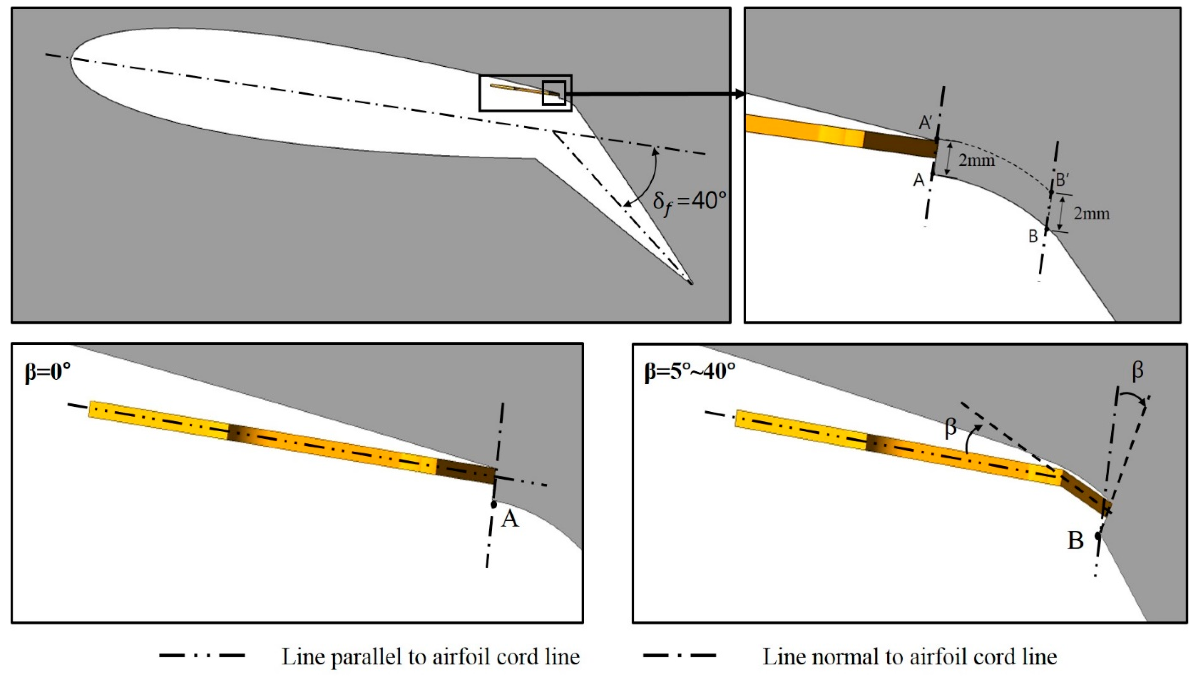
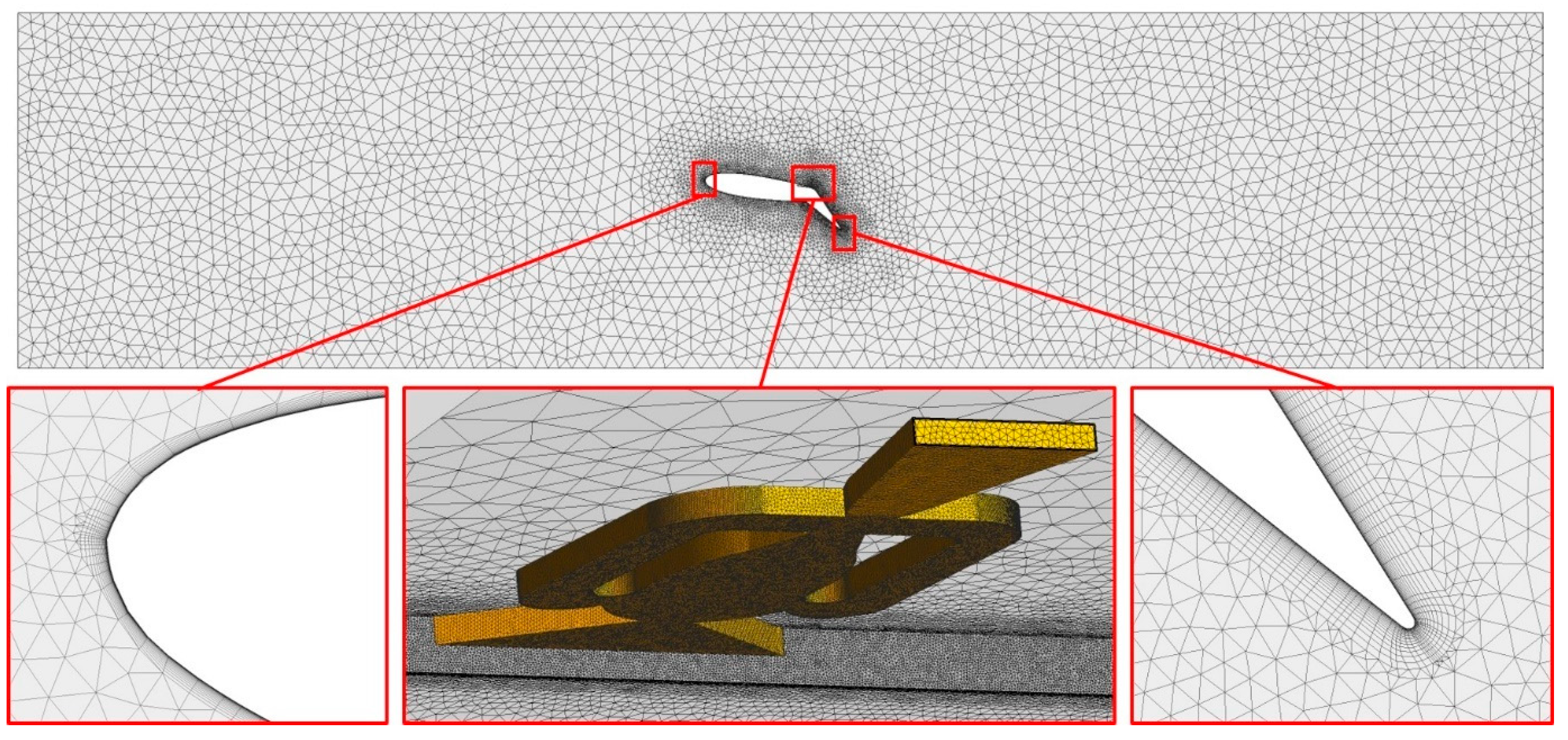
2. Fluidic Oscillator Model and Computational Domain

The fluidic oscillator model used in this study was proposed by Melton et al. [24] and has two feedback channels. They reported that this fluidic oscillator model exhibited excellent flow separation control when mounted on a NACA0015 Airfoil. The geometrical parameters of this model are summarized in Table 1.
In the present work, the effect of a bent outlet nozzle on the fluidic oscillator performance was investigated with and without external flow, and two different cases were considered: the internal flow of a single fluidic oscillator and the interaction between the internal and external flows of fluidic oscillators mounted on a NACA0015 airfoil with a simple hinge flap. Figure 1 shows the computational domain for the internal flow of the fluidic oscillator. Figure 1a,b show the domains for the standard and bent oscillators, respectively. In the case of the bent oscillator, the bending occurs at the throat of the outlet nozzle with a bending angle (β), as shown in Figure 1b. The bending angle (β) varies in the range of 0–40°.
Figure 2 shows the computational domain for the interaction between the internal and external flows of the fluidic oscillators on the airfoil with a flap. This computational domain consists of the internal and external domains of the fluidic oscillators. Using the periodic conditions, only three oscillators are included in the domain. The reason for selecting this oscillator number was presented in the previous work of Kim and Kim [29]. Melton’s experimental work [30] was referenced for the external flow configuration. The angle of attack (α) is fixed at 8°, and the flap deflection angle (δf) is 40°. When δf = 0°, the chord length (c) is 305 mm, and the span (S) is 99 mm. The flap is located at 70% chord from the leading edge of the airfoil, and fluidic oscillators are installed just in front of the flap hinge.
For external flow, the fluidic oscillator’s mounting conditions are shown in Figure 3, which are the same as in the study of Kim and Kim [29]. The main body of the fluidic oscillator was fixed so that it was always parallel to the airfoil’s cord line. Since the pitch and bending angles of the fluidic oscillator coincide, both are expressed as β, and the test range of this angle was determined as β = 0–40° considering the results of the previous work [29]. In the case of β = 0° (reference model), the exit surface of the fluidic oscillator is mounted close to point A’ on plane A-A’, and this plane is perpendicular to the airfoil chord line. However, as β increased, the exit plane was inevitably moved to plane B-B’ to avoid interference with the flap surface. The B-B’ plane is translated 7 mm downstream from the A-A’ plane and rotated by the angle β around point B.

3. Performance Parameters

Two performance parameters were defined to evaluate the performance of the fluidic oscillator depending on the bending angle. The first one is the peak velocity ratio of the oscillating jet at the exit of the fluidic oscillator (FVR), which is defined as follows:
F V R = U p e a k U r e f
where reference velocity U r e f is the velocity at the outlet throat.
U r e f = m ˙ i n l e t A r e f ρ
U p e a k is the peak value of the time-averaged jet velocity at the oscillator outlet, m ˙ i n l e t is the mass flow rate at the inlet, A r e f is the area of the outlet throat, and ρ is the air density at 25 °C.
The second performance parameter is the dimensionless pressure drop (Ff), which directly affects the pumping power:
F f = Δ p D h 2 ρ U r e f 2 S
where Δ p is the pressure drop through the fluidic oscillator, D h   is the hydraulic diameter of the outlet throat, and S is the distance between the inlet and the outlet throat shown in Figure 1.
On the other hand, to evaluate the aerodynamic performance of the airfoil with fluidic oscillators, the lift and drag coefficients are defined as follows:
C L = L 1 2   ρ   U   2   c   s  
C D = D 1 2   ρ   U   2   c   s  
where L, D, ρ, U, c, and s indicate the lift force, drag force, fluid density, velocity, airfoil cord length, and width of the computational domain, respectively. The subscript ∞ indicates free-stream values.

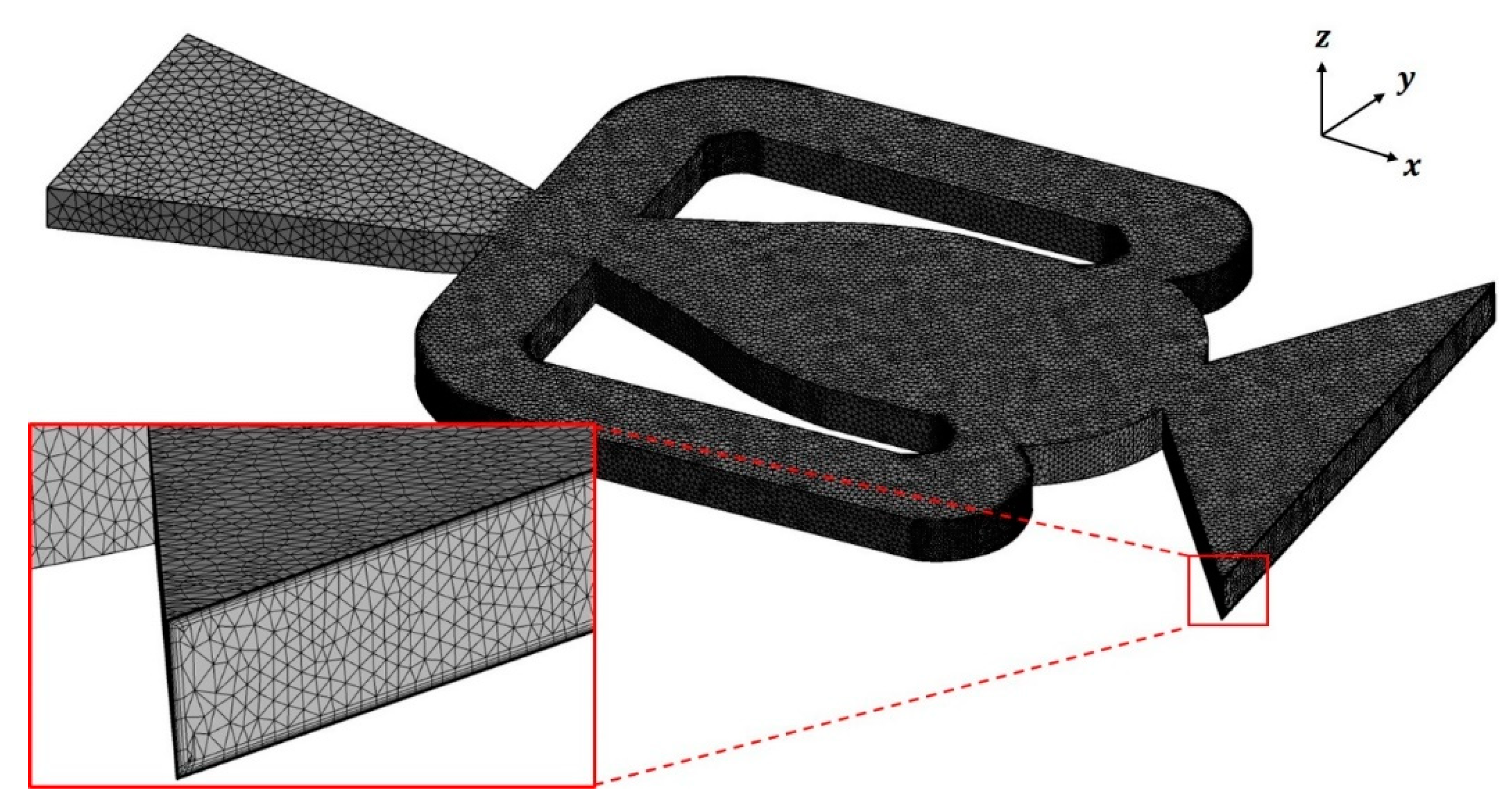
4. Numerical Analysis

In the present work, the commercial CFD software ANSYS CFX 15.0® [31] was used for the flow analysis. In both the analyses of the internal flow of the fluidic oscillator and the external flow on the airfoil, three-dimensional URANS equations with the shear stress transport (SST) turbulence model and continuity equation were calculated numerically. Pandey and Kim [28] reported that URANS analysis with the SST model predicted the internal flow of a fluidic oscillator better than LES with the WALE model. The SST model is also known to predict the flow separation well under adverse pressure gradients [32,33].
For the computational domain inside the fluidic oscillator (Figure 1), the following boundary conditions were used. Uniform velocity was assigned at the oscillator inlet, and no-slip conditions were used at the walls. For the external flow domain shown in Figure 4, a uniform velocity of 25 m/s was assigned at the inlet of the domain, which corresponds to a Reynolds number of 5.0 × 10⁵ based on the inlet velocity and chord length. Constant pressure is assigned at the outlet of the domain, and no-slip boundary conditions are used at the wall. In both the analyses, the working fluid is air at 25 °C, which is assumed to be an ideal gas.
For the external flow, Melton et al. [18] measured the jet frequency of the fluidic oscillator in a range of mass flow rates, m ˙ = 0 1.3 g/s, and evaluated the aerodynamic performance of the airfoil in a range of momentum coefficients ( C μ ), 0–6.63%, for different flap angles. They found that as the mass flow rate increased, the frequency increased but converged to a value. The performance of flow control generally improved as C μ   increased, and a larger value of C μ is required for a larger flap angle to achieve effective flow control. The momentum coefficient is defined as follows:
C μ =   n   ρ j e t U j e t   A n o z z l e   U j e t 1 2   ρ   U 2   c   n   l = 2 A n o z z l e c   l ( U j e t U ) 2
U j e t = m ˙ ρ j e t A n o z z l e = m ˙ ρ A n o z z l e
where U j e t is the velocity at the oscillator outlet, m ˙ is the mass flow rate through the oscillator, and   A n o z z l e is the area of the oscillator outlet. l and n are the space between adjacent oscillators and the number of oscillators. The fluid density in the fluidic oscillator ( ρ j e t ) was assumed to be the same as the density in the external flow ( ρ ) .
In the present study, the bent oscillator was tested in a range of mass flow rates, m ˙ = 0.19–0.72 g/s, and the aerodynamic performance of the airfoil was evaluated in a C μ   range of 0.41–5.94%.
Grid structures in the internal and external domains are shown in Figure 5 and Figure 6, respectively. In both grids, prism meshes were constructed near a wall, and unstructured tetrahedral meshes were used in the other regions. To adopt the SST model developed for low Reynolds numbers, the first grid points near the wall were located at y+ < 2. In both the unsteady analyses of the internal and external flows, the time step was 5 × 10⁻⁶ s. As a convergence criterion, the root-mean-square of the relative residuals was kept less than 1.0 × 10⁻⁴. The total time interval calculated was 0.03 s in each case. The results of the steady RANS analysis were used as the initial assumption for the URANS analysis. The simulation was carried out using a supercomputer employing an Intel Xeon Phi 7250/1.4 GHz processor with 68 CPU cores. The internal flow analysis of the fluidic oscillator took about 8 h, and the analysis of the external flow and three internal flows in the computational domain took about 48 h.

5. Results and Discussion

5.1. Grid Conver

Grid-convergence index (GCI) analyses based on Richardson extrapolation [34] were performed to evaluate the grid dependency of the numerical results. Table 2 shows the results of the GCI analysis for the jet frequency in the internal domain of the fluidic oscillator. The relative discretization error   ( GCI   fine 21 ) of the finally selected grid with 4.7 × 10⁵ cells (N1) was 0.957%. The results of the GCI analysis for the lift coefficient in the external domain are shown in Table 3. The grid with 3.8 × 10⁶ cells was selected in this domain, including internal domains of the fluidic oscillators with a   GCI   fine 21 of 0.072%. The grid selected in Table 3 was also used in each oscillator included in the domain shown in Figure 2.

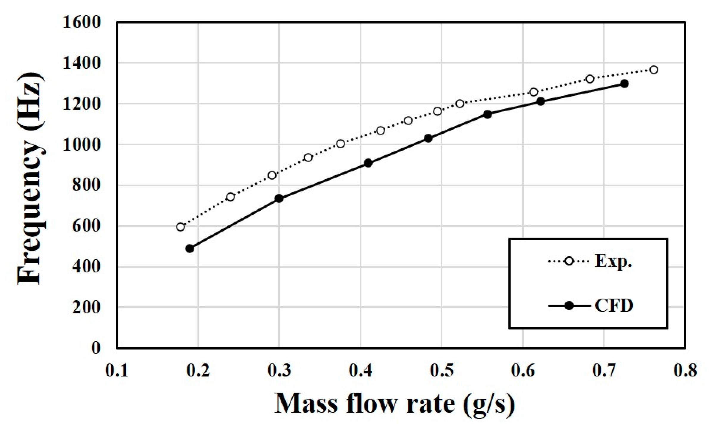
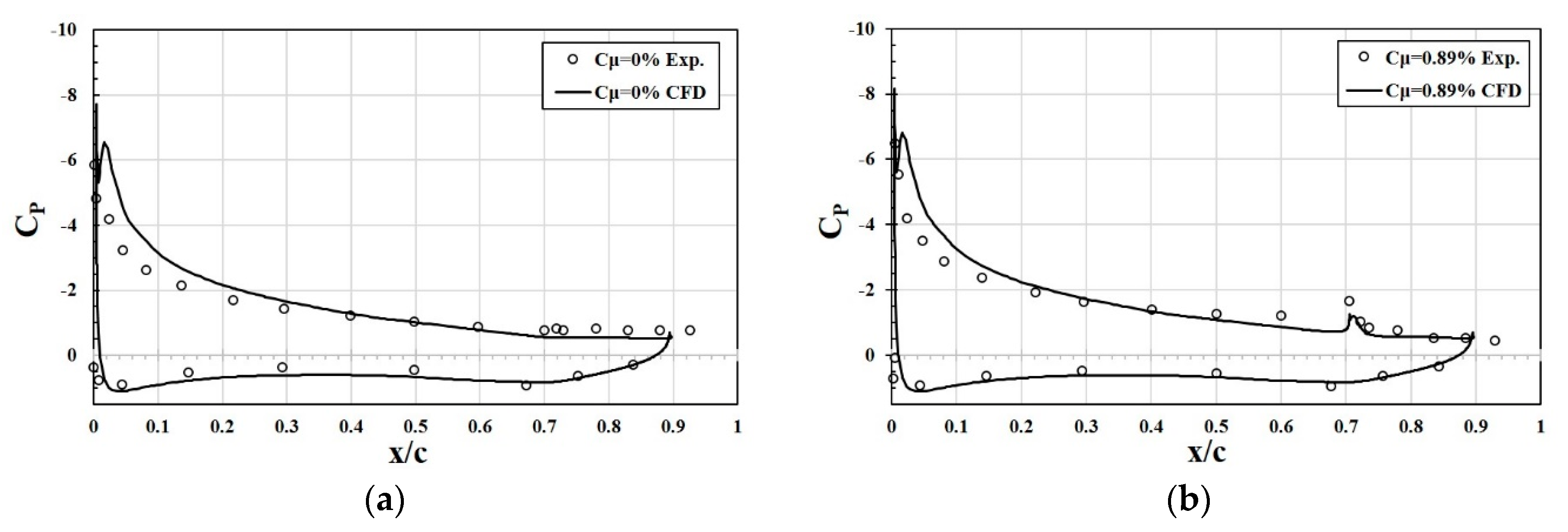
5.2. Validation of Numerical Results

The numerical results for the internal and external flow domains were validated using the experimental data of Melton et al. [18]. Figure 7 shows the comparison between predicted and measured jet frequencies for the internal flow of the fluidic oscillator. The relative error is reduced as the mass flow rate increases and reaches about 2% at mass flow rate larger than 0.7 g/s.
In previous work [29], numerical results were obtained using the same numerical methods used in the present work and validated for the interaction between internal and external flows of the fluidic oscillators. The results were compared with experimental data [18] for the pressure distribution and lift coefficient of a NACA0015 airfoil with a flap angle of 40°, as shown in Figure 8 and Table 4, respectively. In Figure 8, the distribution of the pressure coefficient shows some deviations near the leading edge on the lower surface in both cases with and without oscillators. However, it shows good agreement on the upper surface, which shows lower pressure. In the case of the lift coefficient, the difference between numerical and experimental [18] results decreases rapidly as the angle of attack increases, as shown in Table 4. Several factors such as flap angle, oscillator location, and flow rate seem to be involved in the error.

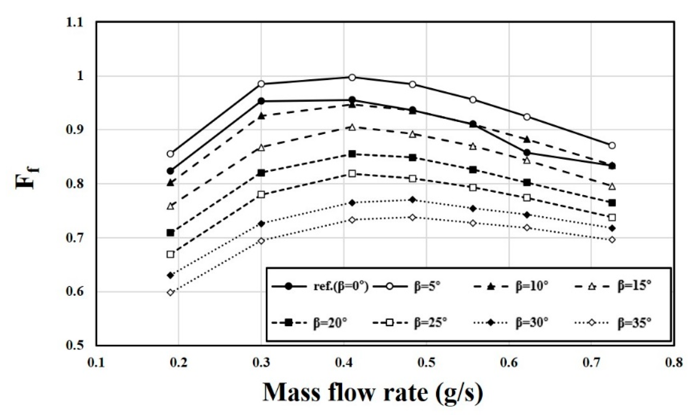
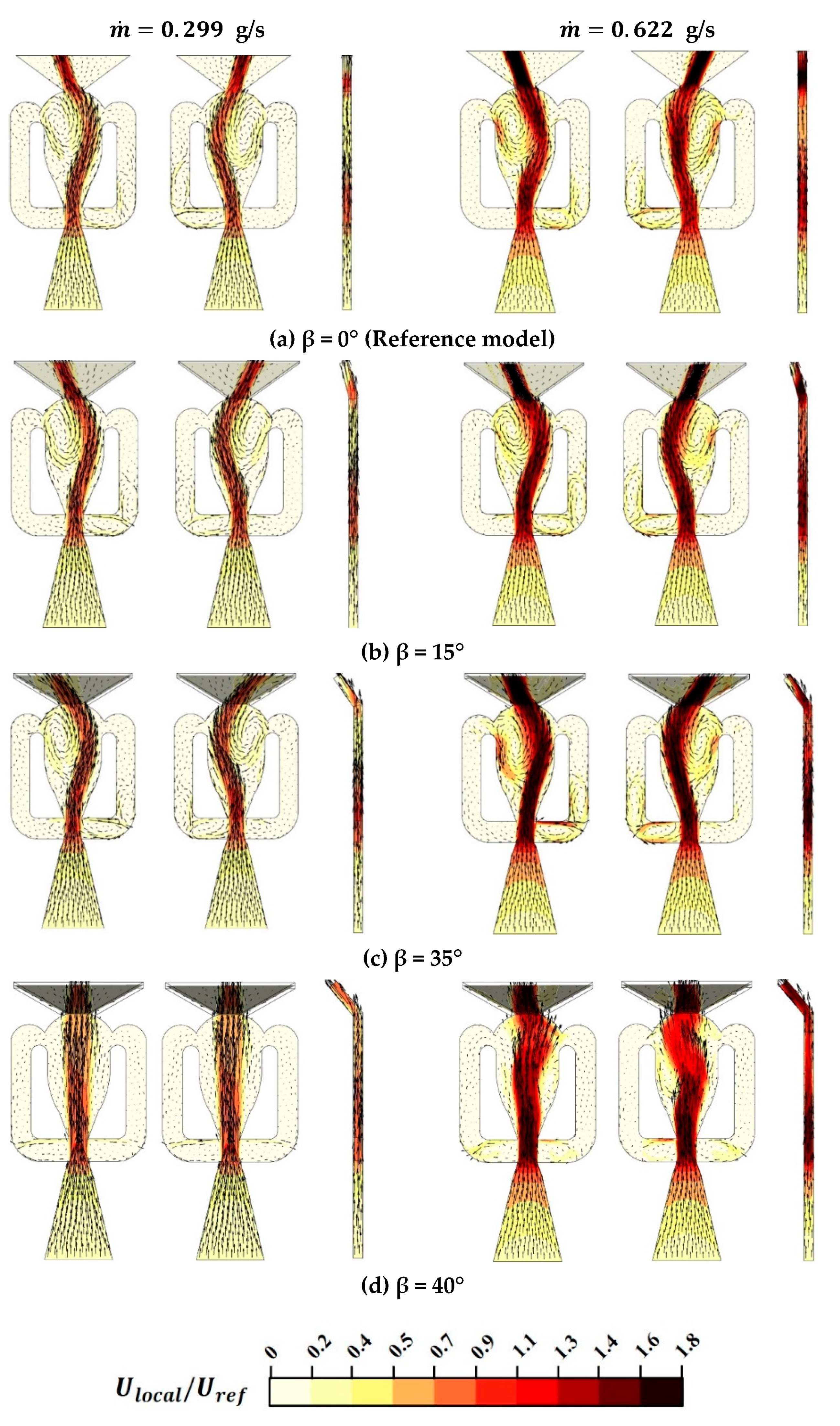
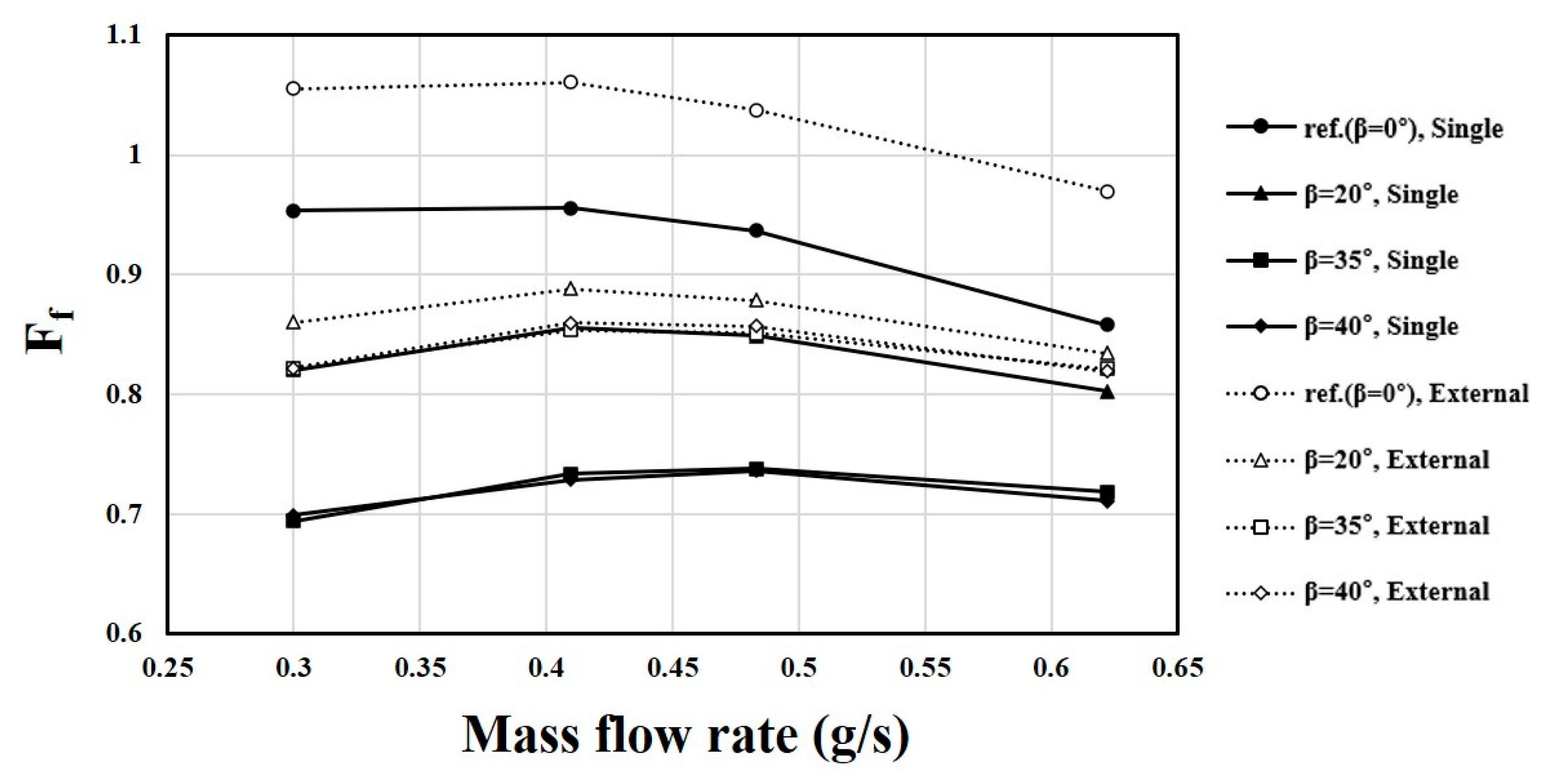
5.3. Single Fluidic Oscillator without External Flow

The effect of a bent outlet on the oscillator performance was first examined for the single fluidic oscillator shown in Figure 1. Figure 9 shows the variations of jet frequency with the mass flow rate at different bending angles for the single fluidic oscillator without external flow (Figure 1). The range of mass flow rate is m ˙ = 0.19 0.72   g / s . The frequency generally increases as the mass flow rate increases. It also increases with the bending angle (β) for the mass flow rates larger than 0.41 g/s. However, β = 20° and 25° show almost the same values of frequency throughout the whole mass flow range.
All the tested bending angles show larger frequencies than the reference model with β = 0 (Figure 1a), regardless of the mass flow rate. In the low mass flow range of 0.2–0.4, the frequency shows similar variations at β = 5–15° and β = 30–35°. However, beyond the mass flow rate of 0.4, the frequency varies differently according to the bending angle. At β = 40°, the frequency largely increases for low mass flow rates ( m ˙ = 0.19   and   0.30   g / s ), but for the mass flow rates larger than 0.3 g/s, the oscillation of the jet disappears, and the jet becomes steady.
Figure 10 and Figure 11 show the variations of peak velocity ratio at the outlet (FVR) and the friction coefficient (Ff) with the mass flow rate at different bending angles, respectively. As shown in Figure 10, the peak velocity ratio generally increases with the mass flow rate for positive bending angles. However, in the case of the reference model (β = 0), FVR has a maximum value of about 0.9 at around m ˙ = 0.4 g/s and shows the lowest values among the tested bending angles for the mass flow rates larger than 0.4 g/s. At m ˙ > 0.5 g/s, FVR increases with β in a range of β = 0–15°, but it decreases with β at β = 15–25°, and β = 15° shows the highest peak velocity ratios among the tested bending angles. In the other range, the variation of FVR with the bending angle (β) is quite complicated.
However, in the case of the friction coefficient, the variations with the bending angle and mass flow rate are relatively simple, as shown in Figure 1. Except for the case of the reference model (β = 0), Ff shows maxima for all the tested bending angles and it increases almost uniformly with the bending angle for β > 0° throughout the whole mass flow range. The maximum Ff occurs around m ˙ = 0.4 g/s for β ≤ 25°, but it shifts to around m ˙ = 0.5 g/s for β = 30° and 35°. The reference model with β = 0 shows values of Ff between those of β = 5° and 10° for mass flow rate less than m ˙ = 0.5 g/s, but it shows values similar to or less than those of β = 10° for m ˙ > 0.5 g/s.
Figure 12 shows the velocity fields in the fluidic oscillator at m ˙ = 0.299 g/s and 0.622 g/s for four bending angles (β = 0°, 15°, 35° and 40°). Two different phases (Φ = 90° and 270°) of the oscillation are shown for each case. It is observed that the angle of jet oscillation at the outlet is reduced slightly as the mass flow rate increases, especially at β = 35°. As the bending angle (β) increases in a range of β less than 40°, the angle of jet oscillation and the jet width increase at both mass flow rates. This is related to the phenomena where the main flow shifts to the wall of the bent outlet opposite to the direction of bending, as shown in Figure 12. This flow shift causes an increase in the peak velocity inside the outlet nozzle and a shift in its location, which seem related to the increase in the jet frequency with bending angle shown in Figure 9. Additionally, the increase in the peak velocity causes a decrease in the pressure, which becomes the reason for the decrease in the pressure drop with bending angle shown in Figure 11. It is also found that the size of the main vortex in the mixing chamber is reduced as β increases. However, the vortex in the feedback channel near the inlet increases with β until β = 35°, especially at the higher mass flow rate. However, at β = 40°, the oscillation disappears as discussed above, even though a slight oscillation remains inside the chamber at the higher mass flow rate.

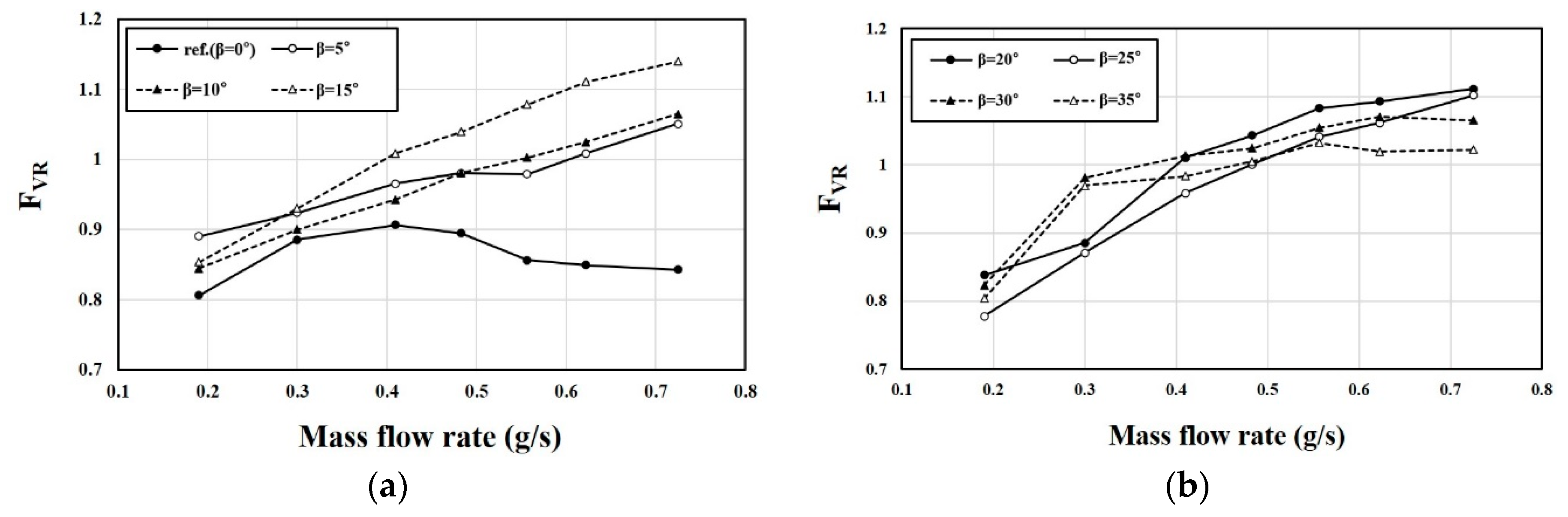
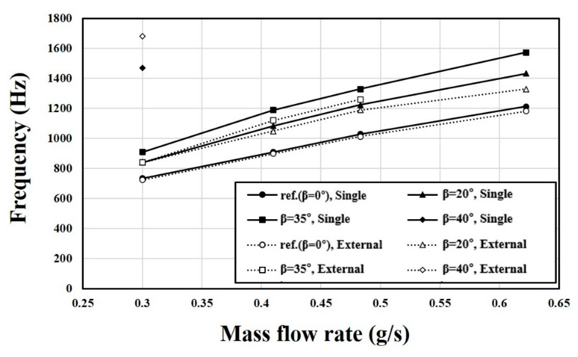
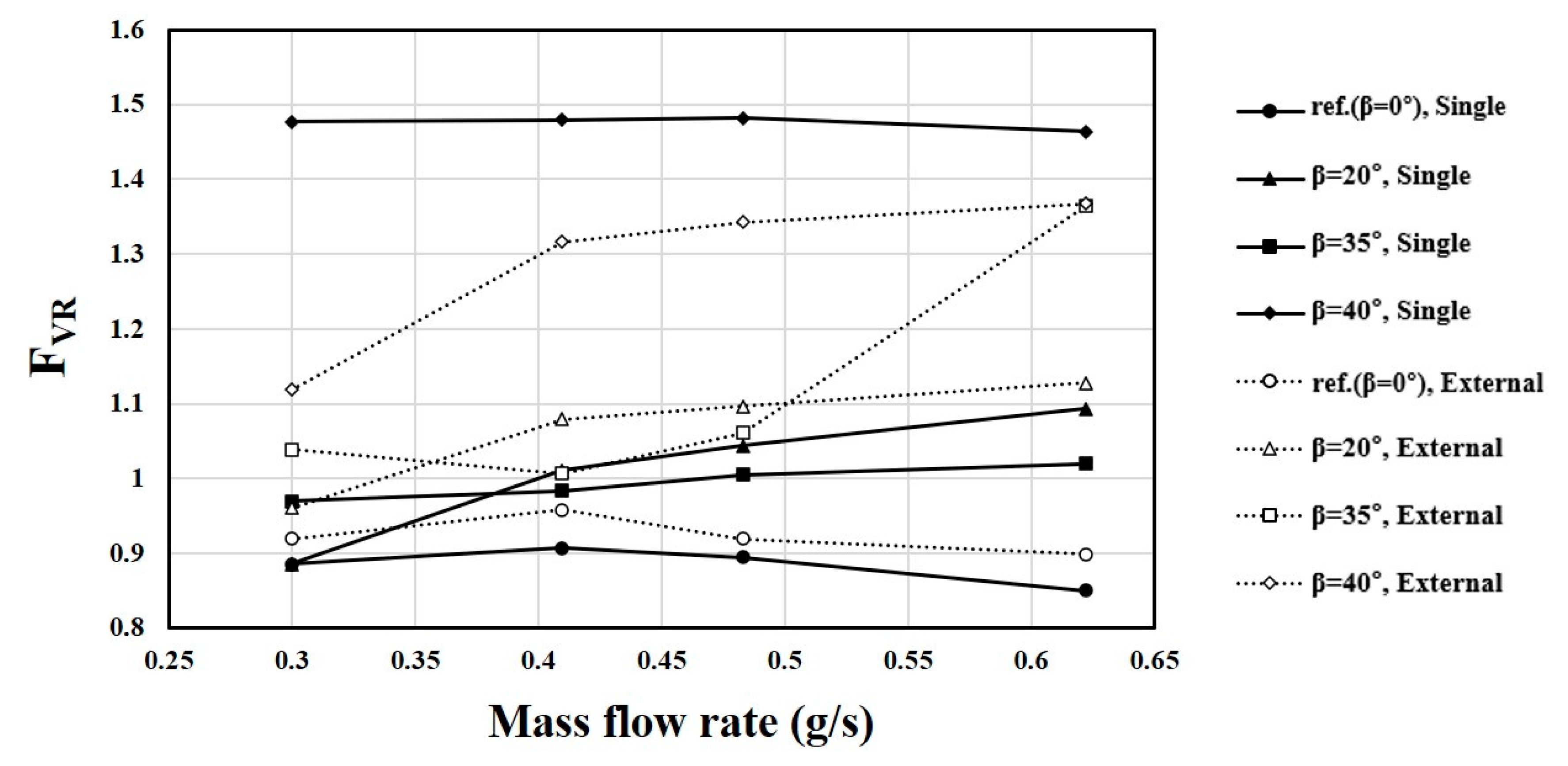
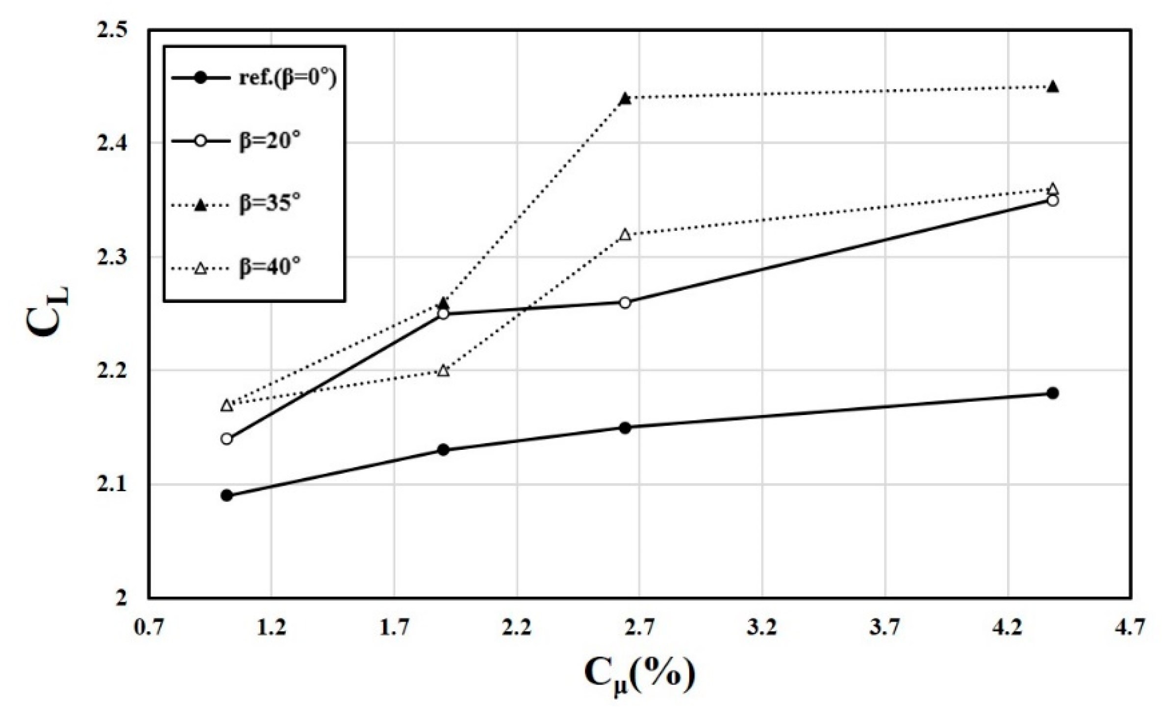
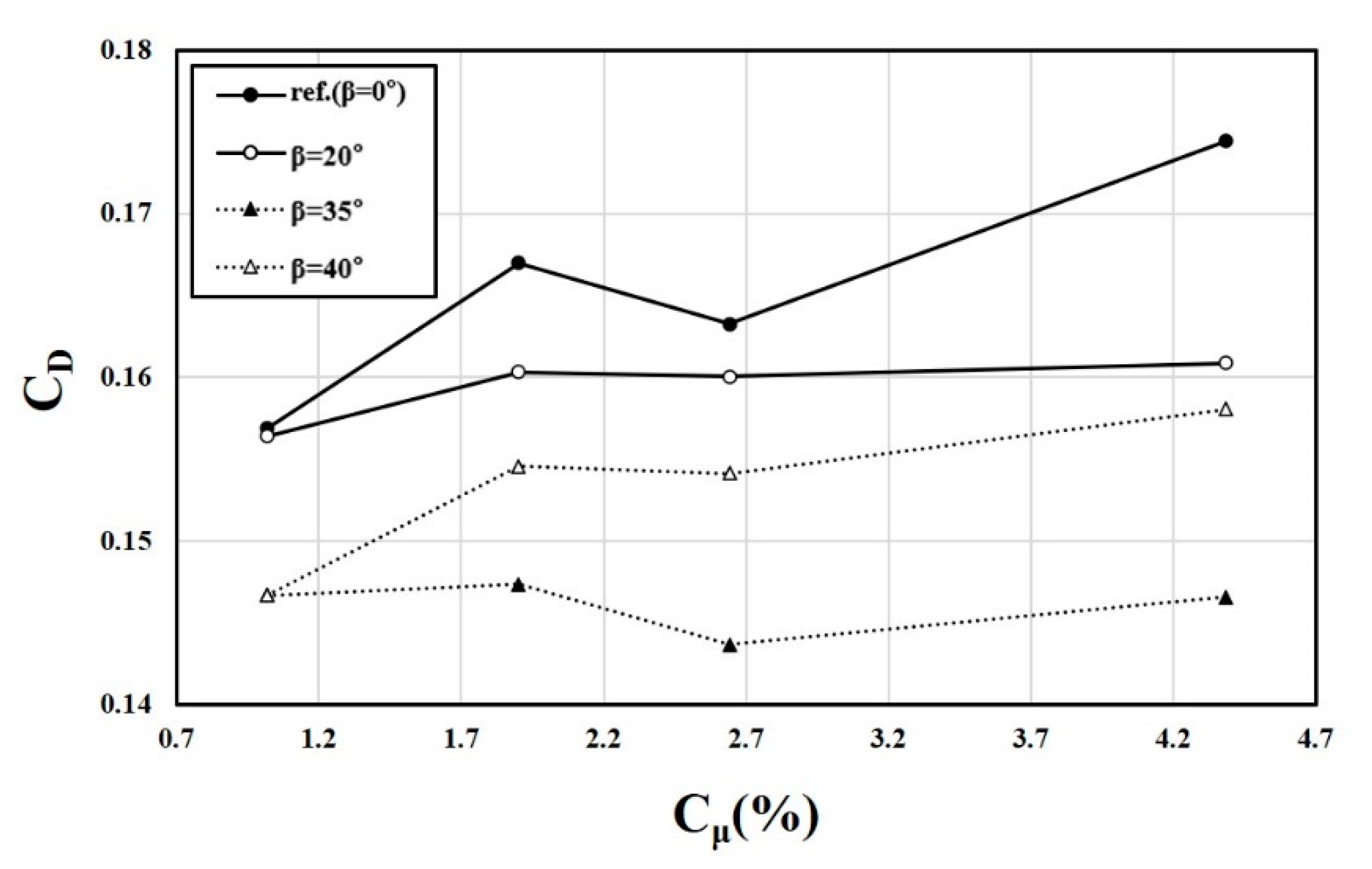
5.4. Effects of External Flow on the Characteristics of the Fluidic Oscillator

The effect of the bending angle on the characteristics of the fluidic oscillators was also evaluated for external flow over a NACA0015 airfoil with a simple hinge flap. With the installation conditions shown in Figure 3, four bending angles (i.e., pitch angles) of β = 0°, 20°, 35°, and 40° were tested. The values of Cμ used for the mass flow rates are presented in Table 5.
Figure 13 shows the comparison between frequencies of the fluidic oscillator with and without the external flow in a range of mass flow rates, m ˙ = 0.30–0.62 g/s. Generally, the external flow reduces the frequency except at β = 40°. The average relative difference in the frequency increases with the bending angle β. For β < 40°, the largest relative difference of 7.62% is found at β = 35° and m ˙ = 0.30 g/s.
With the external flow, the jet from the fluidic oscillator becomes steady at β = 40° beyond m ˙ = 0.30 g/s, as in the case without external flow (Figure 9). At this bending angle, the external flow increases the frequency for m ˙ = 0.30 g/s, unlike the other cases, and the relative difference in the frequency increases up to 14.4%. In the case with the external flow, oscillation of the jet also disappears at β = 35° for the highest mass flow rate of m ˙ = 0.62 g/s, unlike the case without external flow. Therefore, the external flow acts to suppress the oscillation earlier.
The effects of the external flow on the peak velocity ratio of the fluidic oscillator for different bending angles are shown in Figure 14. Except at β = 40°, where oscillation of the jet disappears for high mass flow rates, the external flow increases the peak velocity ratio, regardless of the mass flow rate. However, at β = 40°, the peak velocity ratio shows almost uniform variation with the mass flow rate, and the external flow largely reduces the peak velocity ratio, even for m ˙ = 0.30 g/s (relative difference of 24.3%), where the jet still oscillates. At β = 35°, the peak velocity ratio increases rapidly for m ˙ = 0.62 g/s, where the jet oscillation disappears, showing the largest relative difference of 33.8%. Except for the cases where the jet oscillation disappears, the effect of bending angle on the relative difference in the peak velocity ratio is not remarkable, and the range of the relative difference is 2.33–8.50%.
Figure 15 shows the effects of the external flow on the pressure drop in the fluidic oscillator. The external flow increases the pressure drop by 3–14% at all the tested bending angles, regardless of mass flow rate. The external flow reduces the pressure at the outlet of the oscillator by increasing the velocity there, and this becomes the reason for the increase in the pressure drop through the oscillator with the external flow. The relative difference in Ff does not vary largely with the mass flow rate. β = 20° shows the minimum relative differences, and β = 35° and 40° show similar Ff variations. Thus, there are similar relative differences in the tested range of mass flow rate. The existence of the jet oscillation does not seem to affect the pressure drop.
Figure 16 shows the variations of the lift coefficient (CL) with Cμ for different bending angles. The lift coefficient generally increases with Cμ. The relationship between Cμ and the mass flow rate in the oscillator is shown in Table 5. Except for the steady jets at β = 40°, the lift coefficient increases as the bending angle increases for all Cμ values. Therefore, β = 35° shows the highest lift coefficients among the tested bending angles, but there is no further increase with Cμ for Cμ = 4.38 (i.e., m ˙ = 0.62 g/s), where the jet oscillation disappears. The steady jets at β = 40° show CL values similar to those at β = 20°. This reflects the combined effects of the increase in the pitch angle and the disappearance of the jet oscillation on the lift coefficient. Variations of CL in the tested Cμ range for non-zero bending angles are much larger than that of the reference model.
Figure 17 shows the effects of bending angle on the drag coefficient (CD). The variation of CD with Cμ is generally not large except at β = 0°. Similar to the case of the lift coefficient shown in Figure 16, except for the case of β = 40°, the drag coefficient decreases as the bending angle increases for all Cμ values. However, for the lowest value of Cμ = 1.02, β = 0° and 20° show similar drag coefficients. β = 40° shows much larger drag coefficients than those at β = 35° except for Cμ = 1.02, where the jet oscillation still exists. However, these values with the steady jets are still lower than those of β = 20°, which was probably due to the larger pitch angle.

6. Conclusions

The effects of bending outlet nozzles on the characteristics of a fluidic oscillator were investigated using URANS analysis with and without external flow in a range of bending angles (β) of 0–40°. In the case without external flow, the frequency increased with the mass flow rate and also with the bending angle in a range of mass flow rates larger than 0.41 g/s. The reference model (β = 0°) showed the lowest frequencies for all tested mass flow rates. The largest frequencies were shown at β = 40° for low mass flow rates, but the jet stopped oscillating for the mass flow rates larger than 0.30 g/s.
The peak velocity ratio (FVR) also increased with the mass flow rate except for the reference model, which showed the lowest FVR values for the mass flow rates larger than 0.4 g/s. For mass flow rates larger than 0.5 g/s, FVR increased with β in a range of β = 0–15°, but it decreased thereafter until β = 25°. The pressure drop through the oscillator (Ff) increased almost uniformly with β throughout the mass flow range for β > 0°. Ff showed maxima around m ˙ = 0.4 g/s for β ≤ 25°, which shifted to m ˙ = 0.5 g/s for β = 30° and 35°. The reference model showed an Ff level similar to that of β = 10°.
The external flow was found to reduce the jet frequency, except at β = 40°. The average relative difference in the frequency between the cases with and without external flow increased as β increased. For bending angles less than 40°, the largest relative difference was 7.62% at β = 35° and m ˙ = 0.30 g/s. As in the case without external flow, the jet oscillation disappeared at β = 40° for m ˙ > 0.30 g/s. At this bending angle, the external flow increased the frequency by 14.4% for m ˙ = 0.30 g/s. With the external flow, the jet also became steady at β = 35° for the highest mass flow rate m ˙ = 0.62 g/s, unlike the case without external flow. Therefore, it seems that the external flow generally suppresses the oscillation.
Except at β = 40°, the external flow increased the peak velocity ratio for all mass flow rates. At β = 40°, however, the external flow largely reduced FVR, especially for m ˙ = 0.30 g/s, where the jet oscillation still existed. The effect of external flow on FVR was dominant in the cases where the jet oscillation disappeared, and the effect of β on the relative difference in FVR was not remarkable in the other cases, where the range of the relative difference was 2.33−8.50%. The external flow increased Ff by 3–14% in the tested β range, regardless of mass flow rate. The lowest relative differences in Ff were found at β = 20°. The existence of the jet oscillation did not affect Ff.
As for the lift coefficient of the airfoil, β = 40° did not show the lowest values, but the values were similar to those at β = 20°. This reflects both the positive effect of the increase in the pitch angle and the negative effect of the disappearance of the jet oscillation on the lift coefficient. The drag coefficient generally decreased as the bending angle increased, except at β = 40°, where the drag coefficients were much larger than those at β = 35°, except for Cμ = 1.02, where the jet still oscillated. The results obtained in this study provide information how the characteristics of a fluidic oscillator change with the bending angle of the outlet nozzle, which may be necessary in some practical applications. Improvement in the aerodynamic performance of airfoils using fluidic oscillators would contribute to energy savings in the operation of aircraft. Further research is required to find the difference in the aerodynamic performance of an airfoil between the cases using straight and bending fluidic oscillators.

Author Contributions

N.-H.K. performed numerical analysis and provided original draft manuscript. K.-Y.K. revised and finalized the manuscript. Both authors have read and agreed to the published version of the manuscript.

Funding

This work was supported by the National Research Foundation of Korea (NRF) grant funded by the Korean government (MSIT) (No. 2019R1A2C1007657).

Institutional Review Board Statement

Not applicable.

Informed Consent Statement

Not applicable.

Data Availability Statement

Not applicable.

Conflicts of Interest

The authors declare no conflict of interest.

References

  1. Tesar, V.; Zhong, S.; Rasheed, F. New fluidic-oscillator concept for flow-seperation control. AIAA J. 2013, 51, 397–405. [Google Scholar] [CrossRef]
  2. Gregory, J.; Tomac, M. A review of fluidic oscillator development and application for flow control. AIAA Pap. 2013, 2013–2474. [Google Scholar] [CrossRef]
  3. Cattafesta, L.N.; Sheplak, M. Actuators for active flow control. Annu. Rev. Fluid Mech. 2011, 43, 247–272. [Google Scholar] [CrossRef] [Green Version]
  4. Raman, G.; Raghu, S. Cavity resonance suppression using miniature fluidic oscillators. AIAA J. 2004, 42, 2608–2612. [Google Scholar] [CrossRef]
  5. Hossain, M.A.; Prenter, R.; Lundgreen, R.K.; Ameri, A.; Gregory, J.W.; Bons, J.P. Experimental and Numerical Investigation of Sweeping Jet Film Cooling. ASME J. Turbomach. 2018, 140. [Google Scholar] [CrossRef] [Green Version]
  6. Wu, Y.; Yu, S.; Zuo, L. Large eddy simulation analysis of the heat transfer enhancement using self-oscillating fluidic oscillators. Int. J. Heat Mass Transf. 2019, 131, 463–471. [Google Scholar] [CrossRef]
  7. Cerretelli, C.; Wuerz, W.; Gharaibah, E. Unsteady separation control on wind turbine blades using fluidic oscillators. AIAA J. 2010, 48, 1302–1311. [Google Scholar] [CrossRef]
  8. Feikema, D.; Culley, D. Computational fluid dynamic modeling of a fluidic actuator for flow control. AIAA Aerosp. Sci. Meet. Exhib. 2008, 1–13. [Google Scholar] [CrossRef]
  9. Seifert, A.; Greenblatt, D.; Wygnanski, I.J. Active separation control: An overview of Reynolds and Mach numbers effects. Aerosp. Sci. Technol. 2004, 8, 569–582. [Google Scholar] [CrossRef]
  10. Wen, X.; Liu, J.; Li, Z.; Peng, D.; Zhou, W.; Kim, K.C.; Liu, Y. Jet impingement using an adjustable spreading-angle sweeping jet. Aerosp. Sci. Technol. 2020, 105, 105956. [Google Scholar] [CrossRef]
  11. Al-Battal, N.H.; Cleaver, D.J.; Gursul, I. Unsteady actuation of counter-flowing wall jets for gust load attenuation. Aerosp. Sci. Technol. 2019, 89, 175–191. [Google Scholar] [CrossRef]
  12. Lei, J.; Zhang, J.; Niu, J. Effect of active oscillation of local surface on the performance of low Reynolds number airfoil. Aerosp. Sci. Technol. 2020, 99, 105774. [Google Scholar] [CrossRef]
  13. Zhu, H.; Hao, W.; Li, C.; Ding, Q.; Wu, B. Application of flow control strategy of blowing, synthetic and plasma jet actuators in vertical axis wind turbines. Aerosp. Sci. Technol. 2019, 88, 468–480. [Google Scholar] [CrossRef]
  14. Lee, K.Y.; Chung, H.S.; Cho, D.H.; Sohn, M.H. Flow Separation Control Effects of Blowing Jet on an Airfoil. J. Korean Soc. Aeronaut. Space Sci. 2007, 35, 1059–1066. [Google Scholar] [CrossRef]
  15. Nagib, H.; Kiedaisch, J.; Reinhard, P.; Demanett, B. Control Techniques for Flows with Large Separated Regions: A New Look at Scailing Parameters. AIAA Pap. 2006, 2006–2857. [Google Scholar] [CrossRef]
  16. Koklu, M.; Owens, L.R. Flow Separation Control over a Ramp using Sweeping Jet Actuators. In Proceedings of the 7th AIAA Flow Control Conference, Atlanta, GA, USA, 16–20 June 2014. [Google Scholar] [CrossRef]
  17. Jones, G.S.; Milholen, W.E.; Chan, D.T.; Melton, L.; Goodliff, S.L.; Cagle, C.M. A Sweeping Jet Application on a High Reynolds Number Semispan Supercritical Wing Configuration. In Proceedings of the 35th AIAA Applied Aerodynamics Conference, Denver, CO, USA, 5–9 June 2017. [Google Scholar] [CrossRef] [Green Version]
  18. Melton, L.P.; Koklu, M.; Andino, M.; Lin, J.C. Active Flow Control via Discrete Sweeping and Steady Jets on a Simple-Hinged Flap. AIAA J. 2018, 56. [Google Scholar] [CrossRef]
  19. Seele, R.; Graff, E.; Lin, J.; Wygnanski, I. Performance enhancement of a vertical tail model with sweeping jet actuators. In Proceedings of the 51st AIAA Aerospace Sciences Meeting Including the New Horizons Forum and Aerospace Exposition, Grapevine, TX, USA, 7–10 January 2013. [Google Scholar]
  20. Koklu, M. The Effects of Sweeping Jet Actuator Parameters on Flow Separation Control. AIAA J. 2018, 56, 100–110. [Google Scholar] [CrossRef] [PubMed]
  21. Kim, S.-H.; Kim, K.-Y. Effects of Installation Conditions of Fluidic Oscillators on Control of Flow Separation. AIAA J. 2019, 57, 5208–5219. [Google Scholar] [CrossRef]
  22. Kim, S.-H.; Kim, K.-Y. Effects of installation location of fluidic oscillators on aerodynamic performance of an airfoil. Aerosp. Sci. Technol. 2020, 99, 105735. [Google Scholar] [CrossRef]
  23. Melton, L.P.; Koklu, M. Active Flow Control using Sweeping Jet Actuators on A Semi-Sapn Wing Model. In Proceedings of the 54th AIAA Aerospace Sciences Meeting, San Diego, CA, USA, 4–8 January 2016. [Google Scholar] [CrossRef] [Green Version]
  24. Melton, L.P.; Koklu, M.; Andino, M.; Lin, J.C.; Edelman, L. Sweeping Jet Optimization Studies. In Proceedings of the 8th AIAA Flow Control Conference, Washington, DC, USA, 13–17 June 2016. [Google Scholar] [CrossRef] [Green Version]
  25. Ostermann, F.; Woszidlo, R.; Nayeri, C.; Paschereit, C.O. Experimental Comparison between the Flow Field of Two Common Fluidic Oscillator Designs. In Proceedings of the 53 rd AIAA Aerospace Sciences Meeting, Kissimmee, FL, USA, 5–9 January 2015; Volume 10, p. 6. [Google Scholar] [CrossRef]
  26. Jeong, H.S.; Kim, K.Y. Shape Optimization of a Feedback-Channel Fluidic Oscillator. Eng. Appl. Comput. Fluid Mech. 2017, 12, 169–181. [Google Scholar] [CrossRef] [Green Version]
  27. Pandey, R.J.; Kim, K.Y. Numerical Modeling of Internal Flow in A Fluidic Oscillator. J. Mech. Sci. Technol. 2018, 32, 1041–1048. [Google Scholar] [CrossRef]
  28. Pandey, R.J.; Kim, K.Y. Comparative Analysis of Flow in a Fluidic Oscillator Using Large Eddy Simulation and Unsteady Reynolds-Averaged Navier-Stokes Analysis. Fluid Dyn. Res. 2018, 50, 065515. [Google Scholar] [CrossRef]
  29. Kim, N.H.; Kim, K.Y. Flow control using fluidic oscillators on an airfoil with a flap. Eng. Appl. Comput. Fluid Mech. 2021, 15, 377–390. [Google Scholar] [CrossRef]
  30. Melton, L.P. Active Flow Separation Control on a NACA 0015 Wing using Fluidic Actuators. In Proceedings of the 7th AIAA Journal Flow Control Conference, Atlanta, GA, USA, 16–20 June 2014. [Google Scholar] [CrossRef]
  31. ANSYS. ANSYS CFX-Solver Theory Guide-Release 15.0; ANSYS Inc.: Canonsburg, PA, USA, 2014. [Google Scholar]
  32. Menter, F.R. Two-Equation Eddy-Viscosity Turbulence Models for Engineering Applications. AIAA J. 1994, 32, 1598–1605. [Google Scholar] [CrossRef] [Green Version]
  33. Bardina, J.E.; Huang, P.G.; Coakley, T.J. Turbulence Modeling Validation. AIAA Pap. 1997, 1997–2121. [Google Scholar] [CrossRef]
  34. Celik, I.B.; Ghia, U.; Roache, P.J.; Freitas, C.J.; Coleman, H.; Raad, P.E. Procedure for Estimation and Reporting of Uncertainty due to Discretization in CFD Applications. J. Fluids Eng. 2008, 130, 078001. [Google Scholar] [CrossRef] [Green Version]
Figure 1. Flow configuration and fluidic oscillator model: (a) Reference model, (b) Model with bent outlet nozzle.
Energies 14 04342 g001
Figure 2. Computational domain for the external flow over NACA0015 airfoil with a flap and fluidic oscillators [29].
Energies 14 04342 g002
Figure 3. Installation conditions of fluidic oscillators.
Energies 14 04342 g003
Figure 4. Computational domain using periodic boundary conditions [29].
Energies 14 04342 g004
Figure 5. Grid system in the fluidic oscillator.
Energies 14 04342 g005
Figure 6. Grid system in internal and external domains (α = 8° and δf = 40°).
Energies 14 04342 g006
Figure 7. Validation of numerical results for frequency of fluidic oscillator using experimental data (Melton et al. [18]).
Energies 14 04342 g007
Figure 8. Validation of numerical results for pressure coefficient using experimental data (Melton et al. [18]) for the NACA 0015 airfoil with a flap and fluidic oscillators (x0/c = 0.7, α = 8°, δf = 40° and y/s = 0.5) performed by Kim and Kim [29]. (a) Case I and (b) Case II.
Energies 14 04342 g008
Figure 9. Frequency variations with mass flow rate for various bending angles (β).
Energies 14 04342 g009
Figure 10. Variations of peak velocity ratio with mass flow rate for various bending angles. (a) in the case of the reference model (β = 0) and (b) in the case of β = 20°, 25°, 30° and 35°.
Energies 14 04342 g010
Figure 11. Variations of dimensionless pressure drop with mass flow rate for various bending angles.
Energies 14 04342 g011
Figure 12. Velocity contours and vectors for different bending angles and flow rates (Left: Φ = 90 ° , Center: Φ = 270 ° , Right: x-z cross section).
Energies 14 04342 g012
Figure 13. Comparison of jet frequency variation with mass flow rate between the cases with and without external flow for various bending angles.
Energies 14 04342 g013
Figure 14. Comparison of peak velocity ratio variation with mass flow rate between the cases with and without external flow for various bending angles.
Energies 14 04342 g014
Figure 15. Comparison of Ff variation with mass flow rate between the cases with and without external flow for various bending angles.
Energies 14 04342 g015
Figure 16. Variations of lift coefficient with momentum coefficient for various bending angles (x0/c = 0.7, α = 8°, δf = 40°).
Energies 14 04342 g016
Figure 17. Variations of drag coefficient with momentum coefficient for various bending angles (x0/c = 0.7, α = 8°, δf = 40°).
Energies 14 04342 g017
Table 1. Geometrical parameters of the fluidic oscillator tested.
ParameterValue
Fluidic oscillator width, w (mm)14.3
Inlet nozzle width, wi (mm)2.0
Inlet chamber width, wc (mm)2.03
Outlet throttle width, wt (mm)2.0
Fluidic oscillator height, h (mm)1.0
Inlet nozzle feedback channel width, h f t (mm)2.41
Diffuser angle of outlet nozzle, θdiff (°)107
Distance between the inlet of mixing chamber and the throat, S(mm)15.6
Table 2. Grid-convergence index (GCI) analysis for the internal domain of a fluidic oscillator.
Parameter Value
Number of cellsN1/N2/N34.7 × 105/3 × 105/2.1 × 105
Grid refinement factorr1.3
Computed jet frequencies corresponding to N1, N2, and N3f1
f2
f3
1298.7
1272.4
1176.5
Apparent orderp4.93
Extrapolated values ϕ   ext   21 1308.6
Approximate relative error e   a   21 2.025%
Extrapolated relative error e   ext   21 0.759%
Grid-convergence index GCI   fine 21 0.957%
Table 3. Grid-convergence index(GCI) analysis for the external domain of airfoil with fluidic oscillator.
Parameter Value
Number of cellsN1/N2/N33.8 × 106/3.1 × 106/2.6 × 106
Grid-refinement factorr1.3
Computed lift coefficients (CL) corresponding to N1, N2, and N3CL1
CL2
CL3
2.135
2.147
2.198
Apparent orderp5.51
Extrapolated values ϕ   ext   21 2.131
Approximate relative error e   a   21 0.562%
Extrapolated relative error e   ext   21 0.188%
Grid-convergence index GCI   fine 21 0.072%
Table 4. Validation of numerical results for lift coefficient using experimental data (Melton et al. [18]) for the NACA 0015 airfoil with a flap and fluidic oscillators (x0/c = 0.7, Cμ = 2.15%, α = 8°, δf = 40°).
Angle of Attack (α)Lift CoefficientRelative Error (%)
ExperimentCFD
01.871.4528.9
42.131.7918.9
82.342.139.8
102.432.353.4
112.442.411.2
Table 5. Cμ values according to mass flow rates.
m ˙   ( g / s ) C μ   ( % )
0.3001.02
0.4101.90
0.4832.64
0.6224.38
Publisher’s Note: MDPI stays neutral with regard to jurisdictional claims in published maps and institutional affiliations.

