1. Introduction
Nowadays, the globally increased environmental concern and the hasty need for fossil free electricity generation is leading the energy systems to install and even combine more and more wind and solar power generations. These renewable energy sources (RES) are most prevalent and economic generating sources, gaining attention in both the scientific and the economic sphere, due to their complementary nature and operating conditions, as well as their maturity and reducing costs. Owing to increasing threats of climate change, countries around the world have ambitious targets in terms of wind and solar power deployment. However, large scale deployment of wind and solar power would require substantial grid infrastructure reinforcement and which could be quite time intensive. In order to accommodate the fast growth of RES integration and improve the power system efficiency and reliability, without being limited by grid reinforcement, one option is to combine wind and solar generations to optimally utilise the electrical grid infrastructure, while increasing the share of renewables in the power system leading to development of hybrid power plants (HPP).
In the last few years, the combination of wind and solar, by exploiting their complementary nature and diurnal operation conditions has become a global trend in the transition towards renewable sources driven energy systems. Furthermore, the addition of a storage system in the wind and solar power combination decreases the HPP power output fluctuations, while increasing their dispatchability and revenue through arbitrage. For example, the addition of a storage system to the wind and solar combination can ensure higher energy availability, namely assuring energy reserve availability even when the RES are not producing any power. Furthermore, seen from wind power plant developers’ perspective, the idea to combine wind, solar and storage can enable the entrance into a new potential market for wind power [
1], facilitating additional revenue possibilities, i.e., ancillary services throughout the year or even create a standalone grid for dedicated demand in case of certain grid outages. These benefits, among others [
2,
3], have increased the focus on development of utility scale wind hybrid power plants (HPPs) all over the world. This is highly reflected in the recent position paper of WindEurope [
4], which is listing all the ongoing large HPP projects around the world, such as 60 MW Kennedy Energy Park in Australia, 64 MW Haringvliet HPP in the Netherlands and 78.8 MW Kavithal HPP in India. New large projects are appearing, especially in India, such as 160 MW HPP in Ananthapuramu and many more to come [
5], as India has come out with its National Wind-Solar Hybrid Policy [
6].
The combination of different technologies with various capabilities and nature, such as wind, solar and storage inside utility scale HPPs, as an important trend in the global transition towards fossil free electricity generation, poses several challenges related to the security and reliability of the power systems’ operation. This has resulted both in the intensification of the research on utility scale HPPs [
1,
2,
3,
7] over the last few years, but also in the awareness of the need to adapt and elaborate entire grid codes for HPPs in the near future, to ensure that they can support the power system stability and maintain at high level the security of supply. It should be noted that grid code specifies requirements for solar and wind, therefore, hybrid plant should also be compliant with these requirements. Although the grid codes might need to evolve in future with large deployments of HPPs around the world to take benefit of additional capabilities of HPPs.
Grid codes, generally technology agnostic, are technical specifications that define requirements for any facility connected to power systems to ensure the integrity and safe, secure and economic operation of the power systems. As the European grid codes differed significantly between countries, the European Commission requested the European Network of Transmission System Operators for Electricity (ENTSO-E) to develop a uniform grid code framework for Europe. This resulted in ENTSO-E specifications which were then published as a European Commission Regulation (EU CR) with Requirements for Generators (RfG) [
8]. The RfG includes harmonized definitions and rules for grid connection for different power generation facilities across Europe, but also requires individual transmission system operators (TSOs) to implement the RfG nationally by specifying national parameters within ranges specified in [
8]. This flexibility in terms of parameter ranges was necessary to still accommodate various national conditions across Europe. The EU CR has been supplemented with another EU CR establishing a network code on requirements for grid connection of High-Voltage Direct Current (HVDC) systems and DC-connected generation. However, there is no European code for storage devices, although the EU CR [
8] also applies to pumped storage. Unlike Denmark [
9], many countries do not have specific technical requirements for battery plants. Among other countries, India is one of the countries seeing major installations of HPPs [
5] and has come out with their new grid code in 2019 to include storage to wind and solar power plants [
10]. This is also the case for India, where the need for such grid codes is huge due to the increasing installations of HPPs in India [
5]. The inclusion of storage in the HPPs can have additional challenges, since the storage allows bidirectional flow of power at the grid connection point.
This paper, which has as background an on-going Indo-Danish project titled “HYBRIDize” [
11], aims to provide a thorough insight and understanding of the salient features of the requirements imposed today to the technologies present inside utility scale wind HPPs (i.e., wind, solar and battery), by reviewing and comparing the existing Indian grid code [
10] and EU CR [
8]; EU CR being also particularly illustrated through the recommendations of Danish TSO Energinet [
9,
12]. Most of the countries in Europe, and especially Denmark, have more or less formulated and enforced quite comprehensive grid codes aiming to make the planning and implementation of new HPP projects simpler, streamlined and predictable—unfortunately, this is not yet the case for the Indian code. Recently, India has revised its grid code [
13]; however, this is not yet as comprehensive as the European grid code. EU CR is the most detailed grid code available and most other regulators in the world look up to the EU CR, while developing and revising their own grid codes. As stated in [
14], the Indian government is currently pursuing a very ambitious deployment of renewable energy, targeting to implement 175 GW of renewables by 2022. This deployment involves 100 GW of solar power, 60 GW of wind power, 5 GW of small hydro and 10 GW of bioenergy [
14]. India is therefore the biggest market for HPP, as depicted from recent tenders and government hybrid policy of India which encourage hybrid projects incorporating wind or storage with PV systems to provide improved flexibility and reduce variability. Such a strong trend toward HPPs in India requires the definition of a strong and clear grid code, which is essential for a smooth deployment of HPPs in India. Learning from the experience of European countries, especially Denmark, there is a huge need in India to develop very quickly clear and comprehensive grid codes, which is crucial to ensure a smooth deployment of HPPs. This paper aims, therefore, to support the Indian ongoing process to define and develop their own comprehensive grid codes, which is essential for a secure deployment of HPPs.
Furthermore, it should be noticed that the attention in the paper is on requirements particularly relevant for large power generating modules, referred as “Type D” in the EU CR [
8] and the Danish grid specifications [
12]. The paper only considers requirements applying to Power Park Modules (PPMs) including HPPs as an ensemble of units which is connected through power electronics. The comparison includes active power, reactive power and ancillary services such as power ramp, low voltage ride through, high voltage ride through, frequency support and voltage support.
The paper is structured as follows.
Section 2 describes the utility scale wind HPP. The comparison between the European and Indian grid codes is presented in
Section 3, while in
Section 4, an outlook and discussion on possible future requirements is provided. Finally, conclusive remarks for the HPP grid codes are presented in
Section 4, where the track for future work is also proposed.
3. Comparison between European and Indian Grid Codes
The comparison of the Indian and European grid codes is purely performed based on the available grid codes regulations such as European Commissions regulation [
8], the Indian grid code [
10] and the Danish grid code for electrical energy storage [
9], respectively. Once this is mentioned, it should be underlined that as the EU CR defines the ranges for different parameters, allowing national TSOs to set their specific requirements according to their necessity. In this specific case, the Danish specifications [
12] are considered. The comparison is performed with respect to frequency and voltage operation ranges, active power control/frequency support as well as reactive power control/voltage support.
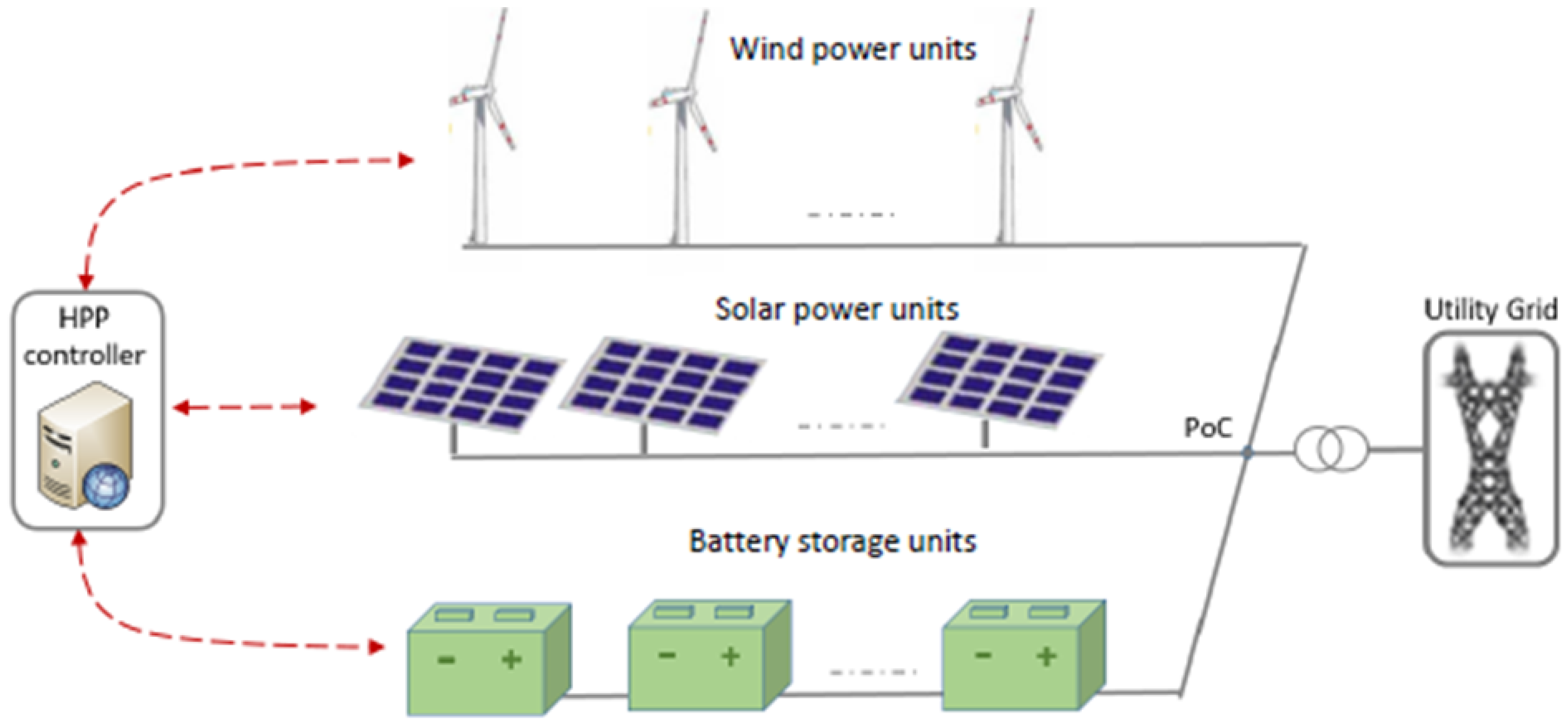
3.1. Sizes
In the EU CR [
8], the power-generating units are categorized according to their connection point as well as their installed capacity, regardless of their source of energy, such as wind/solar.
Table 1 provides an overview of this classification.
Notice that the table also provides the classification of the power generating modules, as well as of the electrical energy storage facilities in Denmark [
9]. Notice that the EU CR does not address all types the electrical energy storage technologies but pumped hydro. In addition, it should be mentioned that utility scale HPPs have typically larger size wind and solar power units and small size storage units. This is the reason why,
Table 1 only depicts Type C or D for power generating modules, while for storage units it depicts different types as Type A, B, C, D. It should be also remarked that the size of the types for storage units is not the same as the size of the types for wind and solar units. Furthermore, according to Danish technical requirements (TR), even if the point of electrical connections for power generating modules and electrical energy storage facilities share the same point of connection to the grid, different grid code requirements shall apply for the power generating modules and the storage facilities. According to the Central Electricity Authority (CEA), namely the Technical Standards for Connectivity to the Grid Regulations [
10], which has developed the Indian grid code there are no classifications on the wind/solar farm/hybrid power plant size.
3.2. Frequency and Voltage Operational Ranges
A utility scale HPP must comply with the grid code requirements for both normal and abnormal operation in respect to frequency and voltage. Grid codes specify frequency and voltage ranges within which the power generating modules should be capable of remaining connected and operate, indicating the minimum times before these modules are allowed to disconnect, depending on the frequency and voltage deviation from the nominal value. EU CR [
8] provides also the minimum times for each European synchronous area, but permit, in some cases, that the relevant TSO can locally demand longer duration. Denmark adapted its grid codes [
12] in conformity to the EU CR, giving specific numbers to the intervals provided by the commission. These numbers apply to wind and solar power units, as well as for other non-synchronous generations. Regarding electrical energy storage plants, Energinet in Denmark has issued an explicit technical regulation, specifying the frequency and frequency operation ranges [
9].
Table 2 provides an overview for Danish and Indian frequency operation range for wind and solar power plants, as well as for electrical energy storage plants, wherever specified. It should be noticed that Denmark is the only European country that consists of two synchronous areas, Western Denmark (denoted by DK1) and Eastern Denmark (denoted by DK2).
TSOs in both countries allow continuously operation below and above the nominal value of 50 Hz within some limited range. As per the Danish, power plants can have unlimited continuous operation in the frequency range of 49–51 Hz. While for frequency ranges if 47.5–49 Hz and 51–51.5 Hz, the power plants are only expected to operate for 30 min. Furthermore, in Denmark, a time operation of 30 min is required beyond the continuous operating range, otherwise the generating units are allowed to be disconnected. In Denmark, a wind and solar power plant must also be capable of continuous generation at frequency changes up to 2.0 Hz/s and is permitted to reduce its active power by 6% of Pn/Hz within 49 Hz–47.5 Hz. Furthermore, in this frequency interval, a wind and solar power plant should trip if the rate of change of frequency (ROCOF) is bigger than −2.5 Hz/s for more than 80 ms. Regarding electrical energy storage plants, the requirements for wind and solar power plants are adopted in Denmark.
As per CEA [
10], any converter connected generating unit (including hybrid power plants) should be able to operate without disconnection between 47.5 and 52 Hz. However, the power plants should be able to generate rated power output only between 49.5 and 50.5 Hz. However, the power plants are allowed to generate rated power output within 49.5–50.5 Hz. The power plants are required to be equipped with governor or frequency controller. The governors may be required to provide frequency response for frequency less than 49.90 Hz and above 50.5 Hz. Although, as depicted in
Table 2, Indian grid code does not specify any requirements specifically for the electrical energy storage plants but the same grid code requirements as above will be applicable if the storage is connected within the wind/solar power plants.
The normal operating voltage ranges differ from country to country. Transmission voltage levels also vary.
Table 3 provides an overview of Danish and Indian voltage operation ranges for wind and solar power plants as well as for electrical energy storage plants, whenever specified. Denmark and India has voltage limits of 0.85–1.1 pu (for 110–300 kV in CE and Nordic system), while India has voltage limits of 0.90 pu to 1.1 pu, and the continuous operation time periods vary from Danish and Indian requirements.
Danish specifications [
9] state that an electrical energy storage unit must be able to withstand voltage deviations at the PoC under normal and abnormal conditions, while reducing the active power as little as possible. These requirements are in line with the Danish specifications for EU CR for power generating modules as shown in
Table 3.
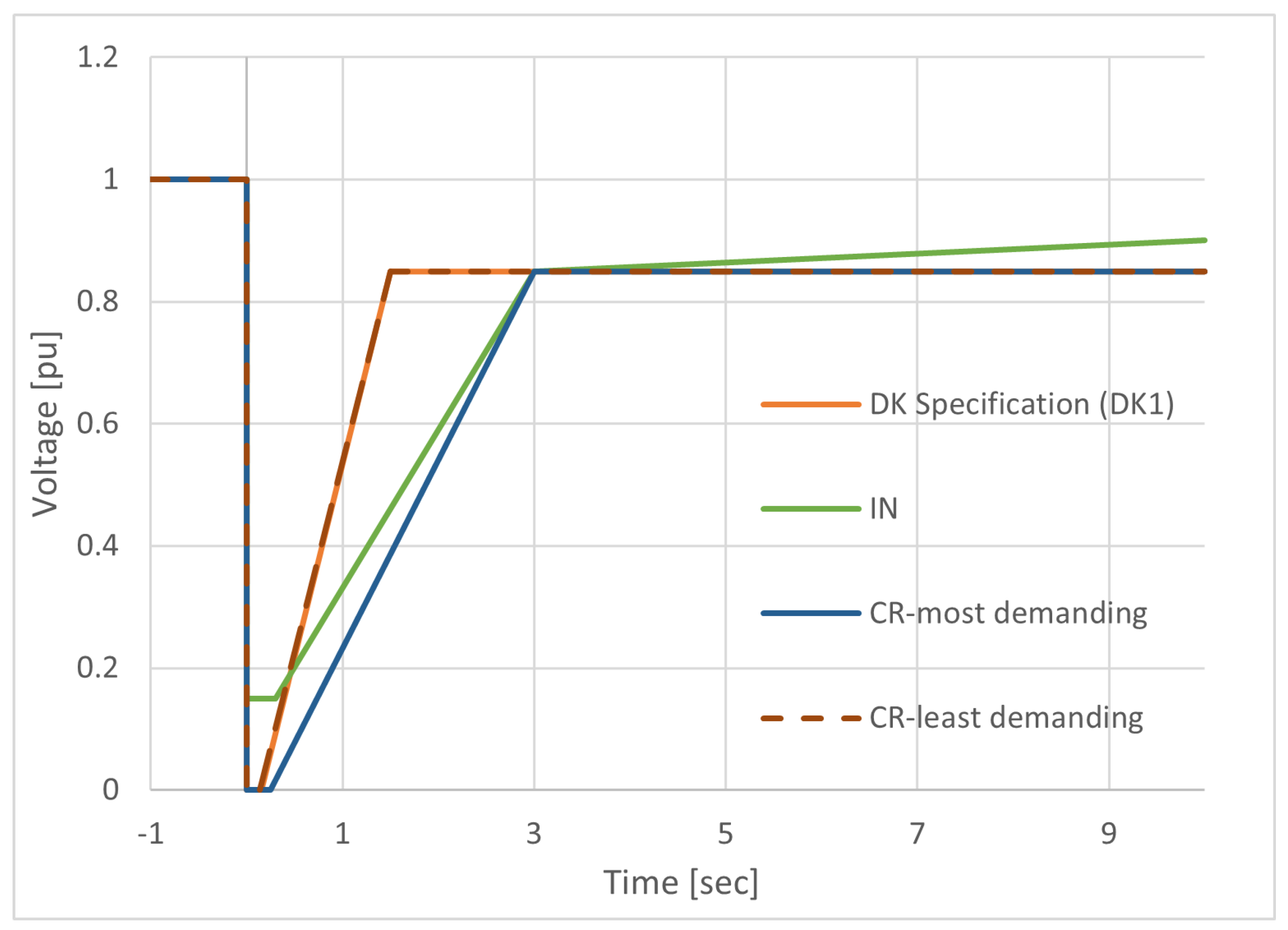
Figure 2 depicts the tolerance to voltage dips, also known as the under voltage ride through (UVRT) capability, for power generating units Type D based on EU CR range, Danish specifications and power generating above 10 MW in India, respectively. Power plant must provide reactive current in order to clear the fault. Additionally, if the power plant is disconnected due to low voltage, frequency deviations can cause due to active power imbalance. In each of the shown cases, a power generating module must be capable of remaining connected to the grid during voltage dips above the solid line corresponding to each plot. In case of voltage dips below the corresponding line, it is allowed to disconnect the plant from the grid. Notice that the EU CR graphs illustrated in
Figure 2 corresponds to the most demanding requirements and least demanding requirements for Type D power generating units. The most demanding requirements require that the plants must withstand zero voltage dips at the PoC over a period of minimum 250 ms without disconnecting. As depicted in
Figure 2, the Danish requirements (both for RES and electrical energy storage plants) follow the least demanding requirements defined by the EU CR. Indian grid code requires that the power generating units connected at 33 kV and above must withstand voltage dips down to 15% of the voltage at the PoC. However, notice that India requires the plants to stay connected to the grid during fault for a period of minimum 300 ms, which is longer than 150 ms required in Denmark. Therefore, the Indian grid code have more demanding requirement during the voltage dip as compared to Danish specifications. The Indian grid code having a stricter requirement during the voltage dip reflects that the Indian grid is not so strong as the Danish specifications, and therefore it is needed to avoid destabilization of the grid during a grid disturbance (in order to support the grid). Notice also that in Denmark power generating units are required to be connected when the post-fault recovery voltage is 0.85 pu (0.85 for CE and 0.9 for Nordic network) within 1.5 s, which is shorter than the Indian requirement of 3 s to voltage recovery level of 0.85 pu. However, the recovery level voltage reaches 0.9 pu in 10 s in Indian grid code.
In terms of overvoltage, Indian grid code requires the power plants to stay connected for 2 s when the voltage is between 1.1 pu to 1.2 pu, and 0.2 s between 1.2 and 1.3 pu respectively. The power plants are allowed to get disconnected for voltages beyond 1.3 pu. Since the power plants needs to stay connected until 1.3 pu as opposed to 1.1 pu in Denmark, it increases the cost of power plants. In Denmark, there are no requirements for overvoltage requirements for power plants connected in transmission networks but there are requirements for the ones connected in distribution networks—1.1 pu/60 s, 1.15 pu/200 ms, 1.2 pu/100 ms.
3.3. Active Power Control
In line with the incorporation of active power control capabilities inside all renewable generating plants, HPPs, as combination of different technologies, will also have to be capable of controlling their active power output with respect to frequency deviation in grid, as well as limiting the ramp rate of their active power output.
3.3.1. Active Power Frequency Response
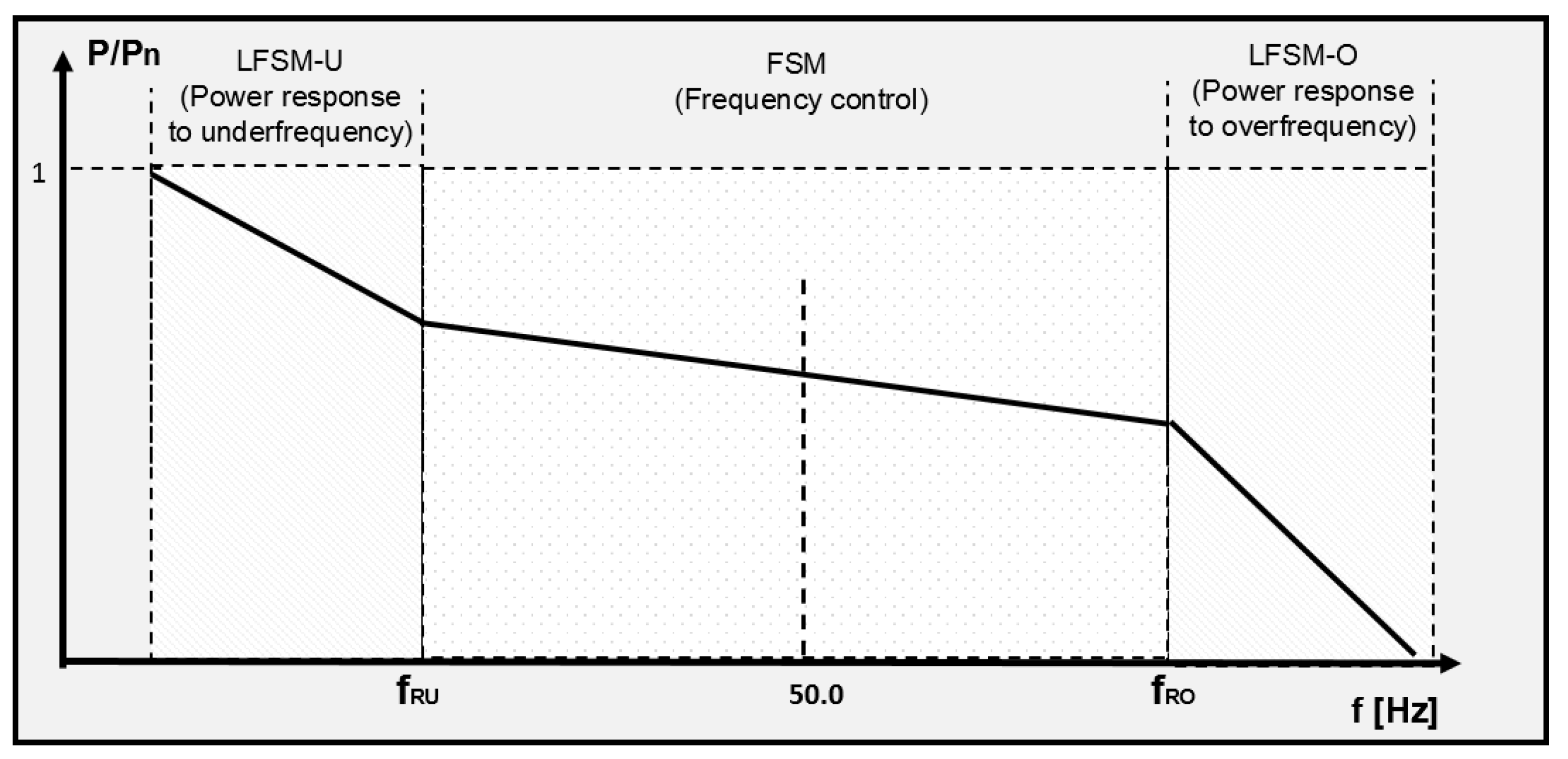
Active power frequency response is defined as the capability to automatically adjust the active power output in response to a system frequency change from the nominal frequency. Power generating plants must be capable of upward or downward regulation of their active power at underfrequency or overfrequency, respectively. EU CR [
8] defines 3 frequency response operating modes for power generating plants, as depicted in
Figure 3:
Limited frequency sensitivity mode—underfrequency (LFSM-U)—where the plants must be capable of upward regulation in response to a fall in system frequency beyond a threshold frequency value , as long as they are operated below their available capacity.
Limited frequency sensitivity mode—overfrequency (LFSM -O)—where the plants must be capable of downward regulation of their active power in response to an increase in system frequency above a threshold frequency value .
Frequency sensitivity mode (FSM)—where the plants must be capable of supplying frequency control, contributing to stabilize the grid frequency.
Table 4 indicates the settings and the ranges for LFSM-U, LFSM-O and FSM in Europe and Denmark. According to Indian grid code [
10], although the frequency controllers are not to be activated until the frequency is below 49.9 Hz or above 50.05 Hz; nevertheless, the controllers should have a dead-band not exceeding
Hz. LFSM-O and LFSM-U are partially covered in Fast Frequency response (as per [
10])—49.7 < f < 49.5 Hz and 50.3 < f < 50.5 Hz. However, important difference is that the EU code has a slope but the Indian grid code has a step response when frequency is beyond the limits. FSM (49.7 < f < 50.3 Hz) is covered as Proportional Frequency response (as per [
10])—which is same as EU CR.
Indian system frequency limit for operation of renewables generator is 47.5–52 Hz. Variations beyond this value lead to tripping of generation. For the frequency range of 49.5–50.5 Hz renewable plants can produce rated power. However, renewable power plants over 10 MW should be equipped with frequency controller with these capabilities- (i) capable to receive active power set point from load dispatch center, (ii) droop control capability of 3–6% and dead band less than
Hz, (iii) ramping capability of 0.1 pu/s for frequency deviation more than 0.3 Hz, (iv) shall have the operating range of the frequency response from 10% to 100% of the maximum power capacity, (v) controlling the active power ramp to be not more than
p.u/min. It should be possible to activate these control functionalities when the frequency is less than 49.9 Hz or greater than 50.05 Hz. Wind and solar generators support frequency stabilisation. Hence for HPP, recommended operating frequency range is 49.5 Hz to 50.5 Hz considering actual measured grid frequency and future improvement initiatives. Frequency deviations >0.3 Hz could range from few second to several minutes. However, there is no clear indication of the duration of frequency support. It can be advised to suggest duration of frequency response of 5 min duration commensurate to wind speed or solar insolation [
13]. Frequency response of various duration (based on capability of plants) could be considered as separate ancillary service and suitable commercial mechanism to compensate for this service to be provided as is the case of European ancillary service markets. It should be further noted that frequency response should be applicable at PCC and not at generating unit. Under frequency response from wind, solar, storage can be technically possible with the provision of headroom. Over frequency response should not be used for normal frequency regulation, but only in case of contingency. The EU CR has provided grid connection requirements for frequency support from renewable plants. However, it should be noted that there lies a challenge in having no test procedure in IEC standard. Therefore, while these grid connection requirements can be expected in the future Indian grid codes, detailed technical description with accuracy, response, curve, insensitivity should be provided to have uniform frequency regulation characteristics.
According to [
9], an electrical energy storage plant in Denmark must be equipped with control functions capable of controlling the active power delivered or absorbed at the PoC. Furthermore, during a frequency event, as indicated in
Figure 4, the electrical energy storage plants must be able to ensure frequency stability by automatically controlling active power at grid frequencies between the pre-determined frequency values
and
within
and
(47.00–52.00 Hz range) with a 10 mHz accuracy. In the event of a system frequency increase, the electrical energy storage plant starts absorbing active power from the grid, while during a system frequency decrease, the electrical energy storage plant starts delivering to the grid. Recommended droop settings for both downward and upward regulation should be in the range of 2–12%.
3.3.2. Ramp Rate
A ramp rate limit indicates the maximum speed by which the active power can be changed in connection with upward and downward regulation and is typically used by TSOs to prevent changes in active power adversely impact on the stability of the public electricity supply grid.
Table 5 specifies the ramp rate limits of generating modules and electrical energy storage units during upward and downward regulation in Denmark and India.
Notice that in Denmark [
12], the ramp rate limit should be within maximum and minimum limits, i.e., 20% and 1% of installed capacity per minute, respectively; however, not exceeding 60 MW/min. Same requirements are also applied for electrical energy storage facilities [
9]. In Indian grid code [
10], it is mentioned that the plants (>10 MW connected at 33 kV and above) shall be capable of controlling the active power with ramp rate not more than ±10% per minute.
3.4. Reactive Power Control
The reactive power control requirements (both dynamic and steady-state) from utility-scale power-generating plants have been tightened over the years. The EU grid code requirements [
8] emphasize that, whenever generating active power, the renewable power-generating plants also should have reactive power control capability, contributing thus to the power system voltage stability.
3.4.1. Reactive Power Capability
The reactive power capability is depending on the type of power-generating plant and is crucial for controlling the voltage locally across an electricity grid, typically in response to power system voltage variations.
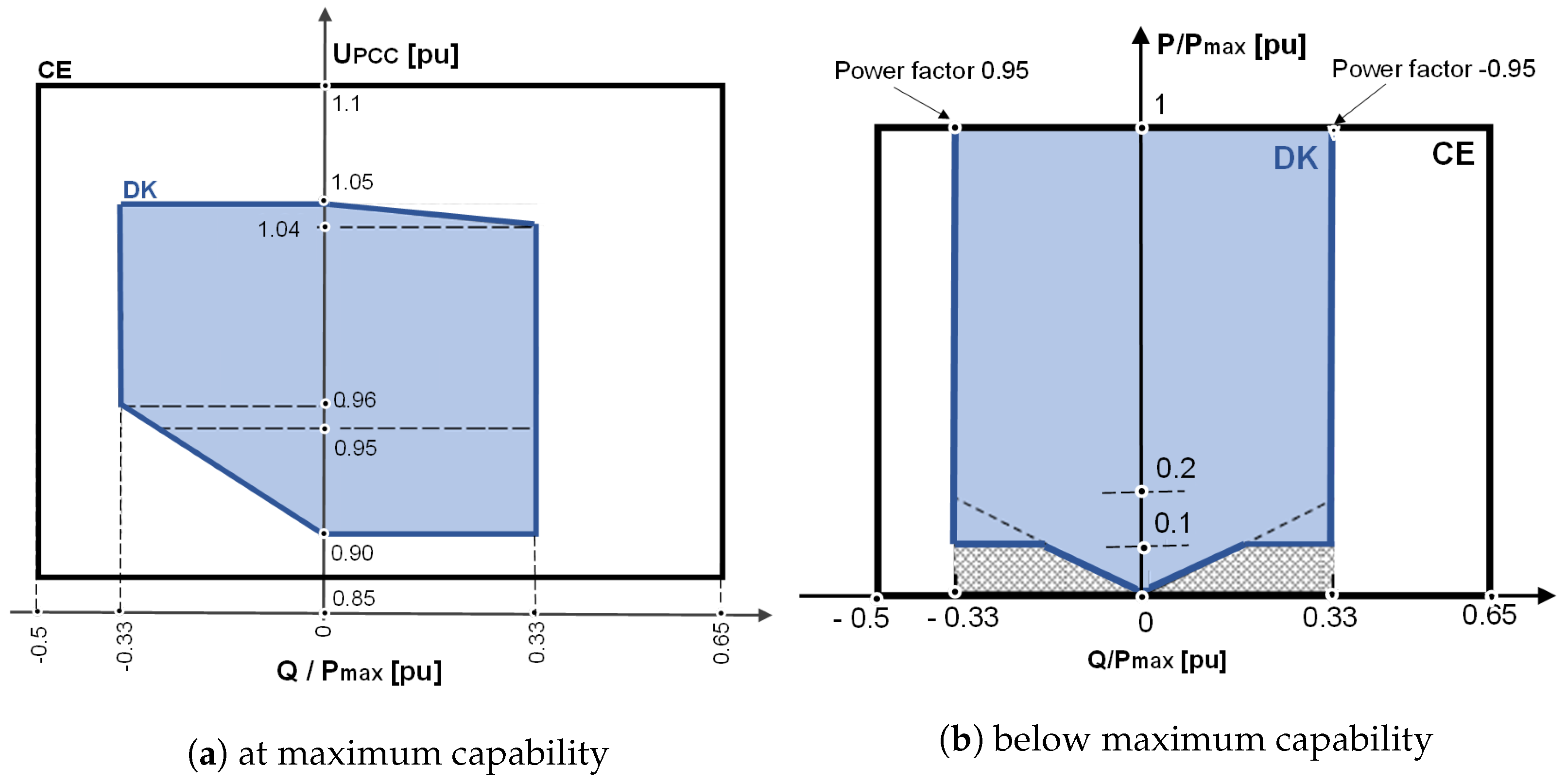
Reactive power requirements are usually specified using U-Q/Pmax profiles and P-Q/Pmax profiles [
8]. Both profiles are for reactive power flow at connection points and define the boundaries in which the power plant shall be capable of providing reactive power. A power generating unit must be capable of supplying reactive power both when it is operating at maximum capacity as well as below its maximum capacity. The U-Q/Pmax profile shows the requirements for reactive power capability at maximum active power capacity at different voltage levels, while P- Q/Pmax profile specifies the requirements for reactive power capability at different active power levels below maximum capacity.
Figure 5 depicts the shapes and values for U-Q/Pmax and P- Q/Pmax profile for Type D power-generating plants in Denmark [
12], respectively. The steady-state reactive power requirements specified by EU CR are indicated in both profiles by an outer envelop (denoted by the black lines), leaving each individual TSO to define its own reactive power requirements through an inner envelope. Power generating units must be designed such that the operating point for the delivery of reactive power can lie anywhere within the specified inner envelop. The inner envelope (depicted by the blue lines) can take on different shapes that vary from area to area, but it should always be positioned within the limits of the fixed outer envelope specified by the EU CR. The blue profile areas depicted in
Figure 5 are showing the steady-state reactive power requirements specified by the Danish TSO [
12]. The grey shaded region in the P-Q/Pmax profile denotes the area where the reactive power capability is allowed to be limited by a reduced number of operating units, due to startup and shutdown as a function of primary energy, maintenance or failure [
12].
The requirements for U-Q/Pmax and P- Q/Pmax profile for electrical energy storage units, defined by the Danish TSO [
9] is same as that of
Figure 5.
While Denmark’s specifications require power generating units to have reactive power capabilities and be able to operate either in voltage, reactive power or power factor control modes, the Indian grid code requires power generating units to have power factors that are dynamically adjustable within the range from 0.95 leading to 0.95 lagging depending on the voltage at point of common coupling (PCC). The requisite reactive power at the point of grid interface must be developed either by RES or should be supplied locally using reactive power compensation devices.
3.4.2. Reactive Power Control Modes
According to [
8,
9,
12], during steady-state operations, large scale power generating units/electrical energy storage units should be capable to provide reactive power control through one of the following control modes, namely either voltage (V) control, reactive power (Q) control or power factor control. All these three control modes are mutually exclusive, which means that only one of them can be activated at a time. The choice of the control mode for a power generating unit/electrical energy storage unit is done in coordination between the TSO and plant operator.
In
V control mode, power generating units should be capable of controlling the voltage at the PoC through reactive power exchange with the network. The reactive power of the power generating unit is varied according to a PoC voltage droop, namely proportionally to the PoC voltage within the capability limits to keep the voltage stable. Voltage droop control is also typically applied to coordinate voltage control from multiple power generating units. In
Q control mode, power generating units or electrical energy storage units should be able to control the reactive power at the PoC to a reactive power set-point, independently by the active power and voltage at PoC. The set-point can be anywhere in the reactive power range as per the grid code requirements. The
power factor control mode requires power generating units to control the reactive power proportionately to the active power at the PoC, according to a fixed power factor set-point which is set within the reactive power range of the capability. A power-generating plant may not exchange reactive power with the public electricity supply grid unless otherwise agreed with the system operator, i.e., the plant will produce at a Power Factor of 1 by default, which implies that there is no exchange of reactive power from the power generating unit to the grid.
Table 6 depicts the characteristics of the reactive power control modes in Denmark and India, according to [
10,
12], respectively.
In accordance with EU network codes [
8], the Danish grid codes require power generating units to be capable of voltage control at the PoC with voltage ranging from 0.95 pu to 1.05 pu, with a deadband of ±5% of reference 1 pu network voltage. As depicted in
Table 6, the Danish TSO Energinet recommends voltage control droop values between 2–7% range and that 90% of the voltage recovery is completed within 5 s. Notice also that the Danish specifications require that the Q control from one set point to another must be initiated within two seconds and completed within 30 s. Regarding Power Factor control, it must be initiated within two seconds and completed within 30 s.
Table 6 reveals also the Danish specifications for electrical energy storage units, with respect to the three control modes.
The Indian grid code does not explicitly define P-Q/Pmax and U-Q/Pmax profiles for the power generating units. Following Indian grid code requirements [
10], system operators permit power generating units to operate as long as voltage at PCC stays within tolerance limits. The voltage at the power plant end is typically controlled by adjusting the transformer’s tap changer settings. Different voltage or reactive power control equipment are generally used to fulfill reactive power requirements. As depicted in
Table 6, the Indian grid code requires specifically power generating units operating above 66 kV to be capable of continuous operation within the power factor range from 0.95 leading to 0.95 lagging. During voltage dips, the Indian grid code [
10] specifies that the supply of reactive power is prioritised before the supply of active power. An active power reduction within the power plant’s design specifications is tolerable. However, active power should be restored to at least 90% of its initial value before the fault within 1 sec of restoration of voltage.
4. Discussion and Conclusions
This paper has provided a thorough insight and understanding of the requirements imposed today to individual technologies present inside utility scale HPPs (i.e., wind, solar and electrical energy storage) by reviewing and comparing the Indian and European grid codes, the last one being particularly exemplified through the Danish. The focus has been on the requirements particularly relevant for large utility scale power plants connected directly to the grid (referred to as “Type D” in EU CR). The comparisons, summarized in
Table 7, have been performed with respect to frequency and voltage operation ranges, active power control/frequency support as well as reactive power control/voltage support. Notice that both countries provide specifications for continuous and abnormal frequency and voltage operation ranges, respectively. However, it is important to note that sometimes the fundamental way of measuring voltages and frequency are not clearly defined in Indian grid code. For example, even though it is mentioned that voltage reference for UVRT/OVRT is based on phase voltages, but it is not clear how the voltages are to be measured (instantaneous or averaged over certain time).
As mentioned before, the frequency regulation is narrower in Denmark compared to Indian grid, namely a more narrow continuous operation frequency band (i.e., 49 Hz to 51 Hz) while Indian grid code has wider frequency band (47.5–52 Hz) for the continuous operation. This implies that power plants connected to Indian power system needs to sustain wider frequency deviations and therefore would make the cost of the power plants higher. Increase in cost is more pronounced for voltage requirements. Indian grid code requires the power plants to ride through overvoltage events and stay connected for voltages up to 1.3 pu. These requirements are not present in EU CR. As depicted in
Table 7, under voltage fault ride through (UVRT) capability is also defined in both grid codes. By analysing UVRT regulations in both countries, it is remarked that the Danish grid code has the shortest UVRT time, while the Indian grid has a more severe UVRT requirement, asking to keep recovery ability for longer time and this due to the fact that the Indian grid is not so strong as the Danish grid.
Although frequency response is included both in EU CR and Indian grid code as both fast frequency response (LFSM) or droop based primary response (FSM), the requirements in Indian grid code are very brief and abstract. Details should be provided in terms of frequency resolution, frequency measurement accuracy, etc. In addition, since the grid frequency of Indian power system is generally fluctuating due to generation-load imbalance; it is not clear that whether frequency response from the power plants would be utilized for contingencies or for minimizing other imbalances. This issue becomes more challenging for the Indian power system because of the reason that the procurement of the frequency reserves are done for long term, making it difficult for weather based generations to participate in the market.
The requirement of ramp rates depends on penetration level and connection point of most of the power generating units into the grid. Indian grid code and Danish specifications have ramp rates that should be adequate to meet high/low share of renewables in the power system. Further, the active power regulation as per Indian grid code from 10% to 100% can be very demanding for weather based generations.
Regarding reactive power requirement, PQ-profiles and UQ-profiles are not considered in Indian grid code explicitly, as compared to Denmark. Furthermore, Denmark’s specifications require power generating units to have reactive power capabilities and to be equipped with voltage, reactive power and power factor control functionalities. The Indian grid code requires power generating units to have power factors that are dynamically adjustable within the range from 0.95 leading to 0.95 lagging at PCC. It is also pertinent to mention here that the Indian grid code requirements can be recommended to have these requirements at PCC and not at the unit level.
This comparison of the requirements imposed today to individual technologies present inside large scale utility HPPs (i.e., wind, solar and electrical energy storage) in the Indian and Danish specifications, is the first step towards awareness of the need for elaborating entire grid codes for HPPs in the near future. Through the paper, it has been depicted that the regulations of India and Europe, explicitly Denmark, vary quite considerably due to the difference in the penetration share of renewable generating sources and operation procedures of power systems. Compared to Denmark, India seems to have a weak power system and therefore, it is important to understand the impact of such power generating units on power stability issues. Learning from the experiences from various European countries like Denmark, India has started defining in more details its grid code. Future improvements of the the Indian grid code can be crucial for supporting grid stability, especially with ambitious installation plans for large scale wind/solar/HPPs projects are upcoming especially in India. Indian grid codes can be segregated with respect to the type of generation i.e., a specific grid code for RES detailing all requirements for wind, solar and electrical energy storage systems may be considered in light of growing demand for RES and as already implemented in Denmark.
Additionally, Denmark and Indian grid code committees may consider the possibility of allowing standalone HPPs forming the grid (first for rural/hilly/isolated areas then extend to industrial areas, Special Economic Zones (SEZs) and commercial zones) in near future paving way for large/full scale RE grid. Industrial areas and SEZs are “usually” willing to pay higher for good power quality, reliable and dedicated power generation. Rural areas have smaller demand so it would be economical to have pilot HPP projects (where no grid is available yet) which can be planned to be integrated with the larger grid once funds/budget is available. Putting this point in grid codes will ‘surely’ accelerate the RE penetration. This will also support in phasing out conventional fossil fuel based generation and encourage a grid formed by RES. Grid authorities (and grid codes) may consider allowing captive HPP for industrial/SEZ facilities. The relevant connectivity and safety regulations shall be formulated.
References yes


 ,
, 


