
Impedance Matching Method for 6.78 MHz Class-E2-Based WPT System


Abstract
:
1. Introduction
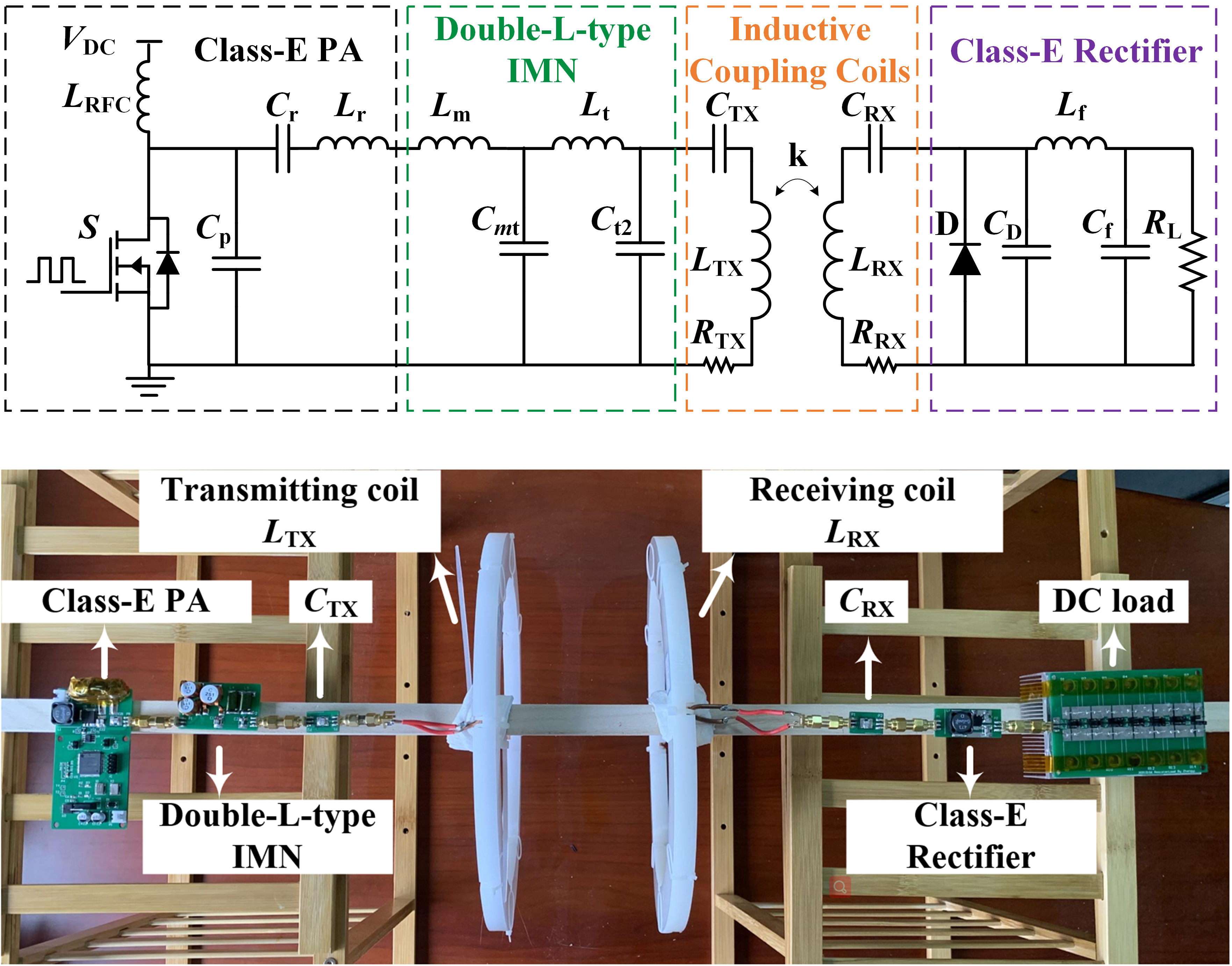
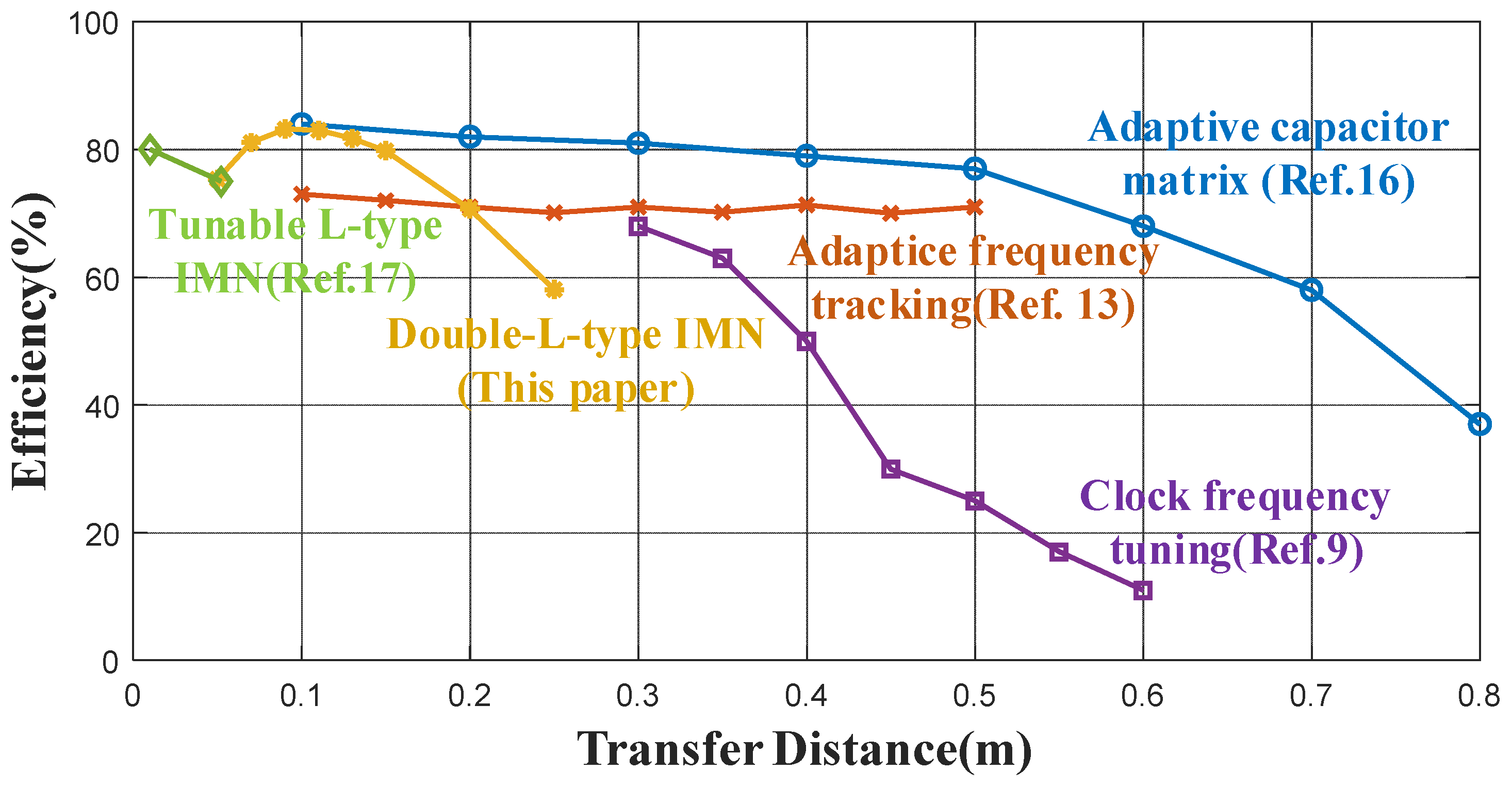
- A novel double-L-type IMN is proposed in the design of a Class-E2-based WPT system. System efficiency is significantly improved over a much wider range of coupling coefficient and load variations.
- A practical design procedure for building a high-efficiency WPT system with strong robustness is developed in this paper.
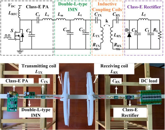
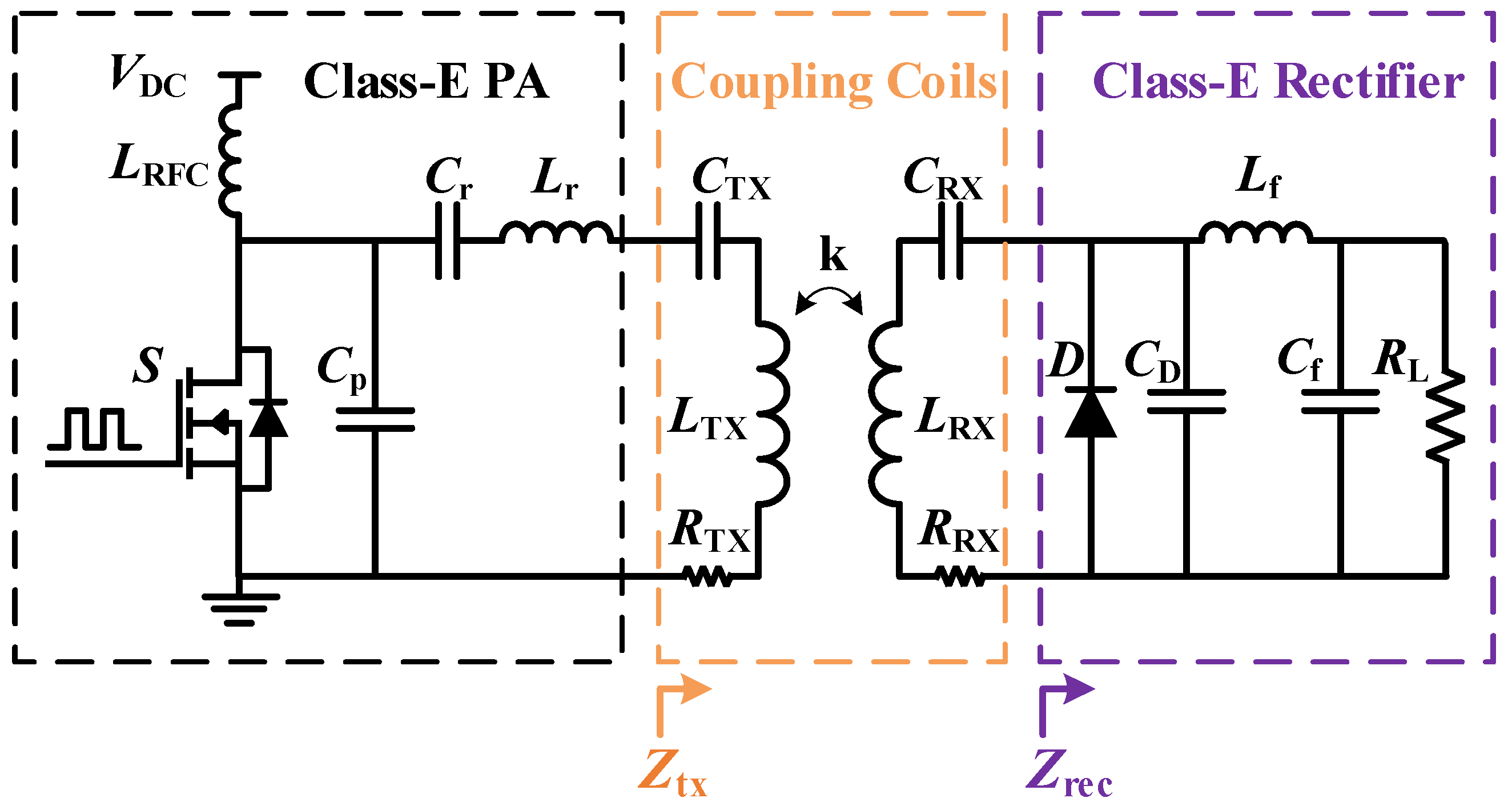
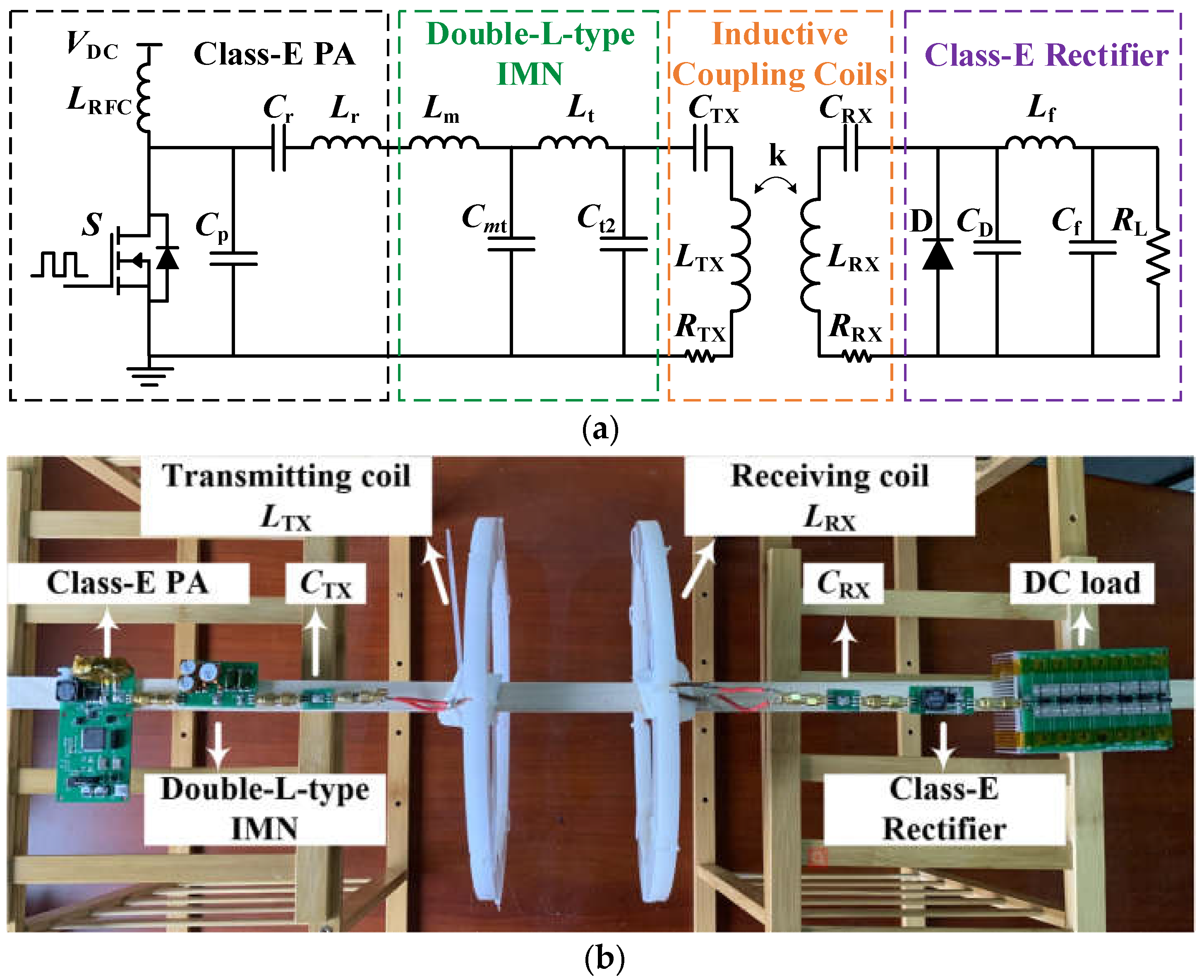
2. Analysis of a Conventional Class-E2-based WPT System
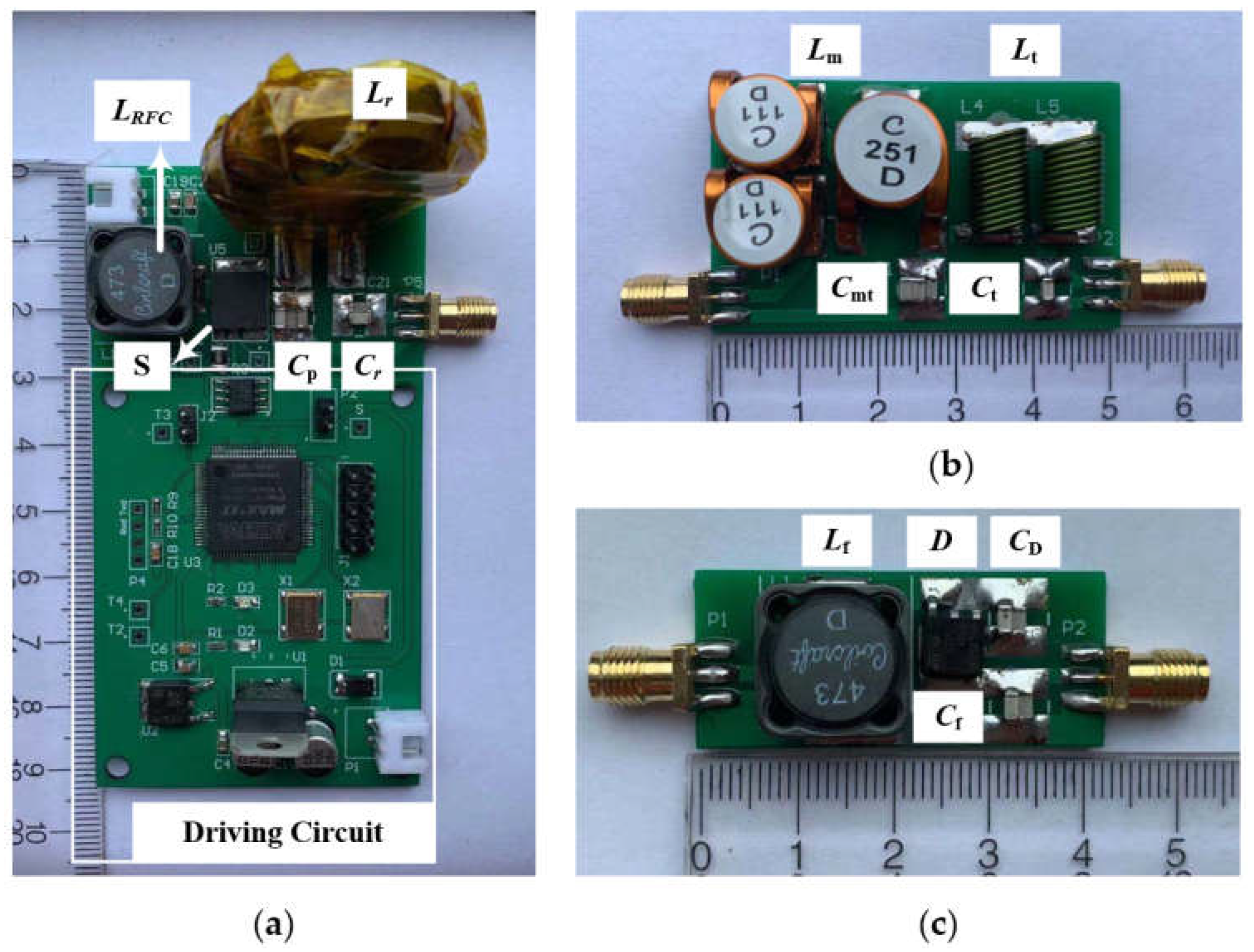
2.1. Design Procedure for Conventional Class-E PA
2.2. Coupling Coils and Class-E Rectifier
- The rectified diode is an ideal diode, whose on-conduction voltage drop and reverse recovery are zero;
- The filter inductor is large enough and the current ripple flowing through Lf-Cf low pass filter is negligible;
- The input of rectifier is considered to be an ideal current source.
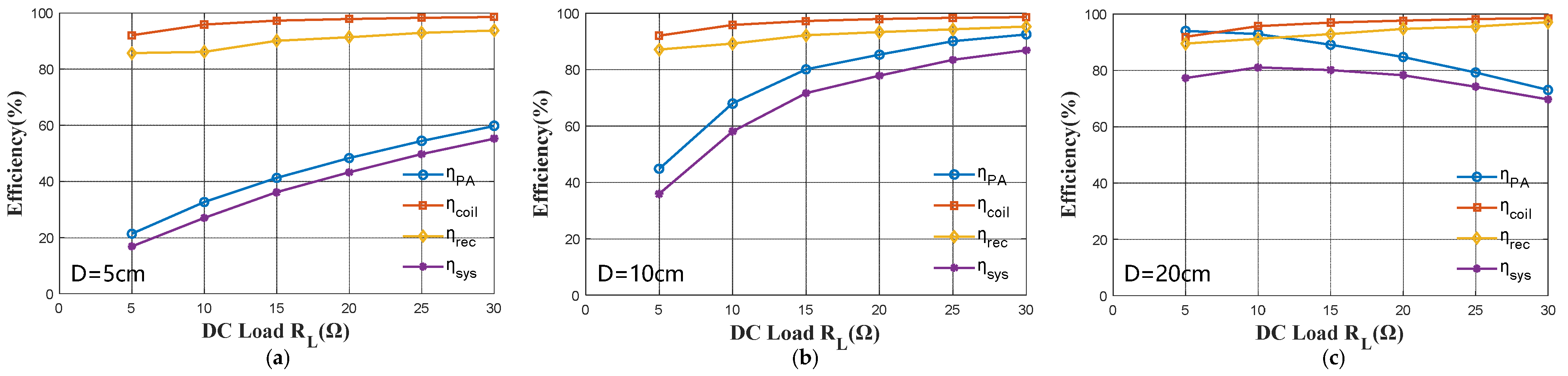
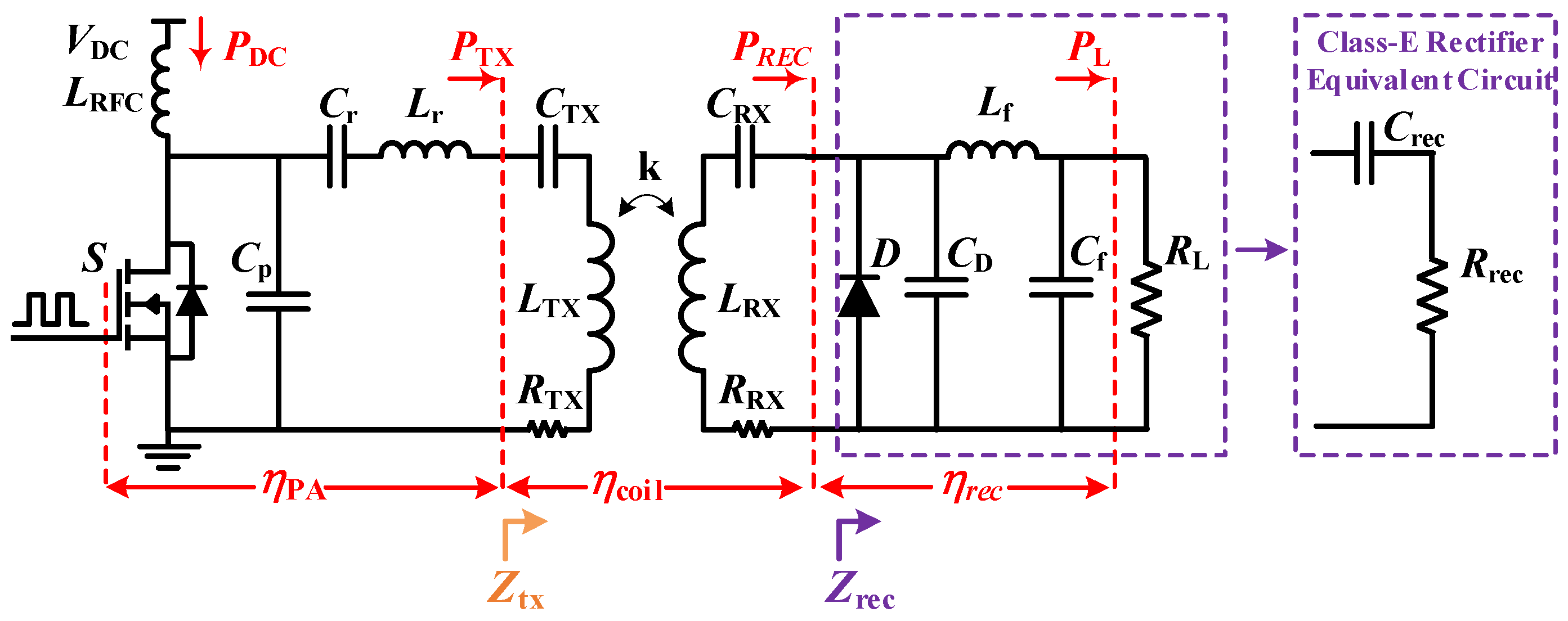
2.3. System Efficiency Analysis
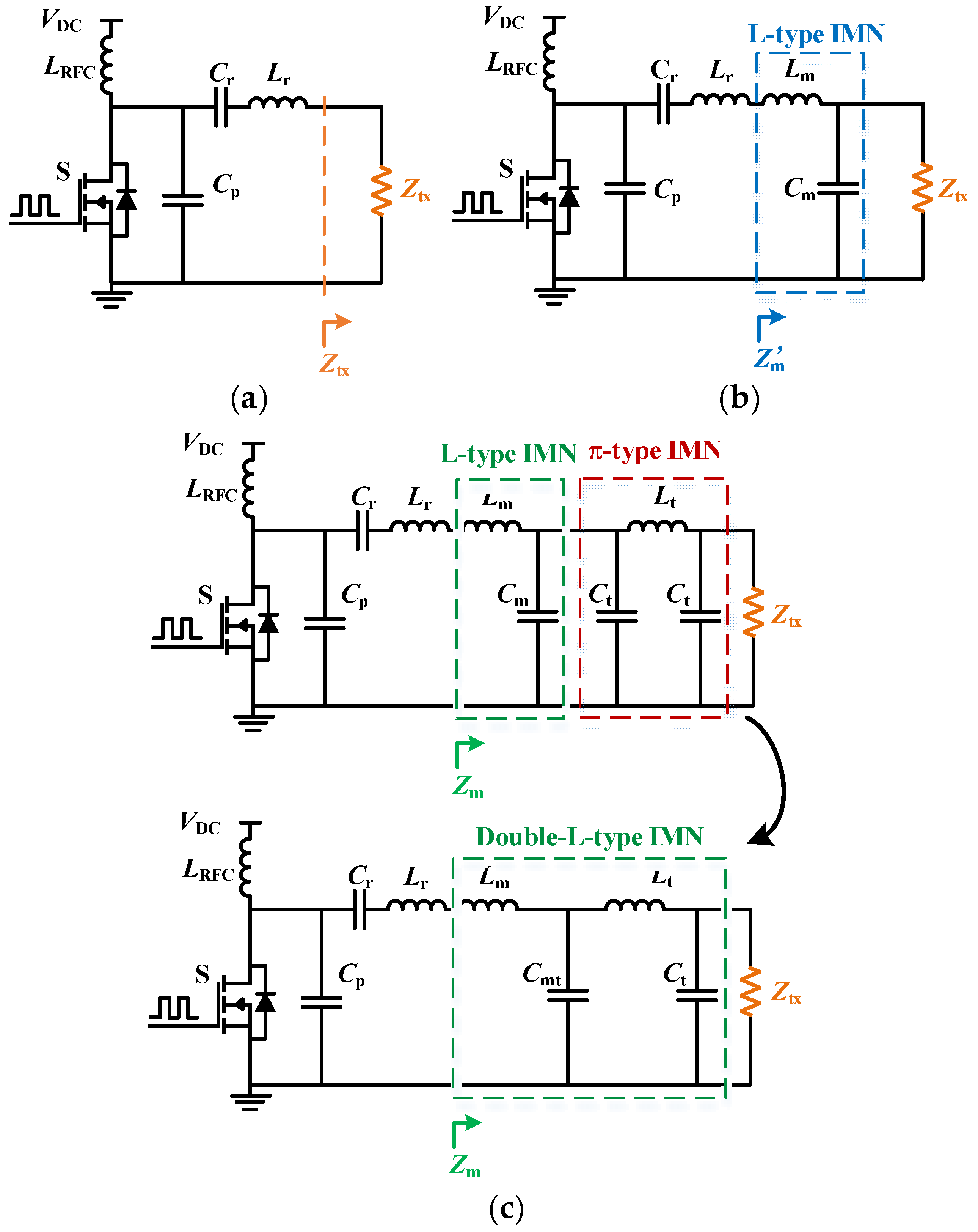
3. Proposed Impedance Matching Method for Class-E2-Based WPT System
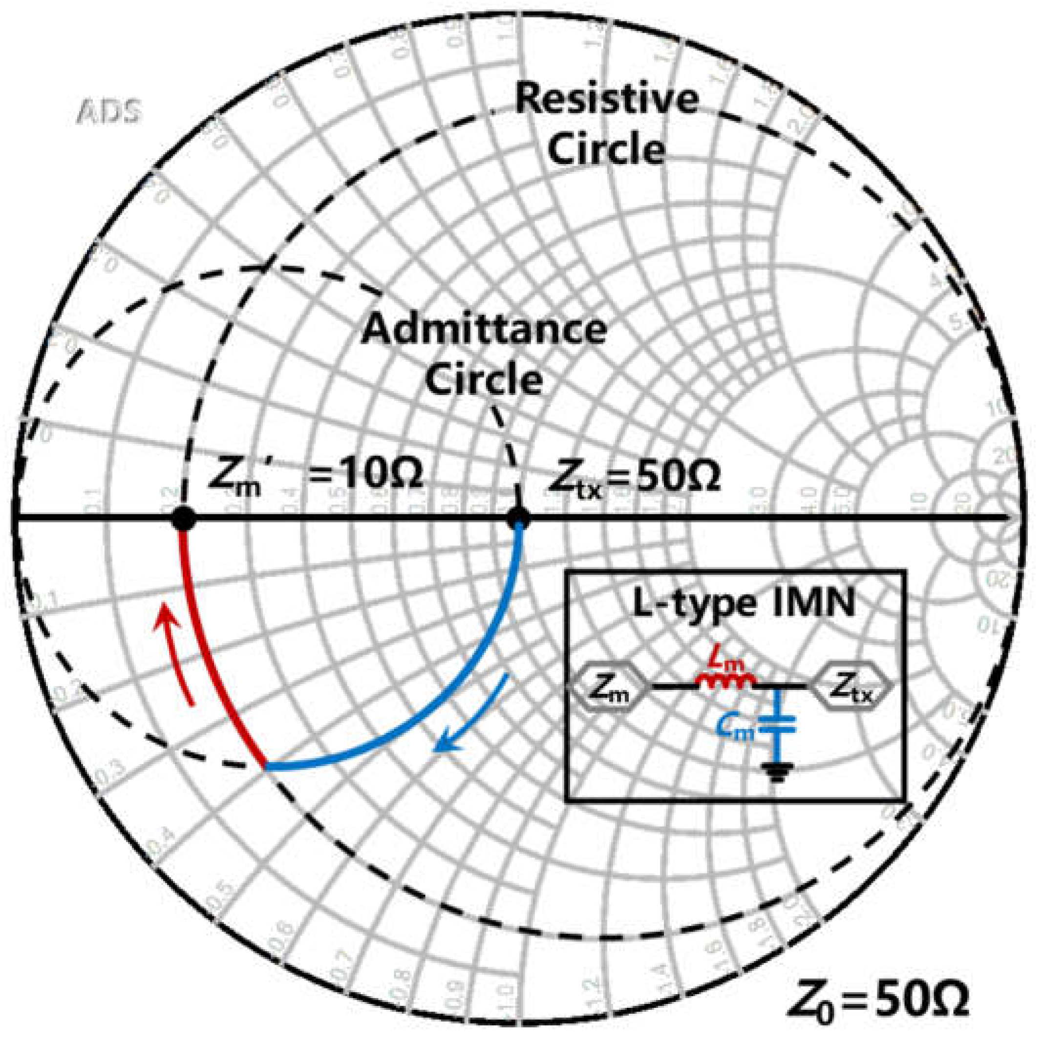
- L-type IMN is employed for preliminary impedance transformation;
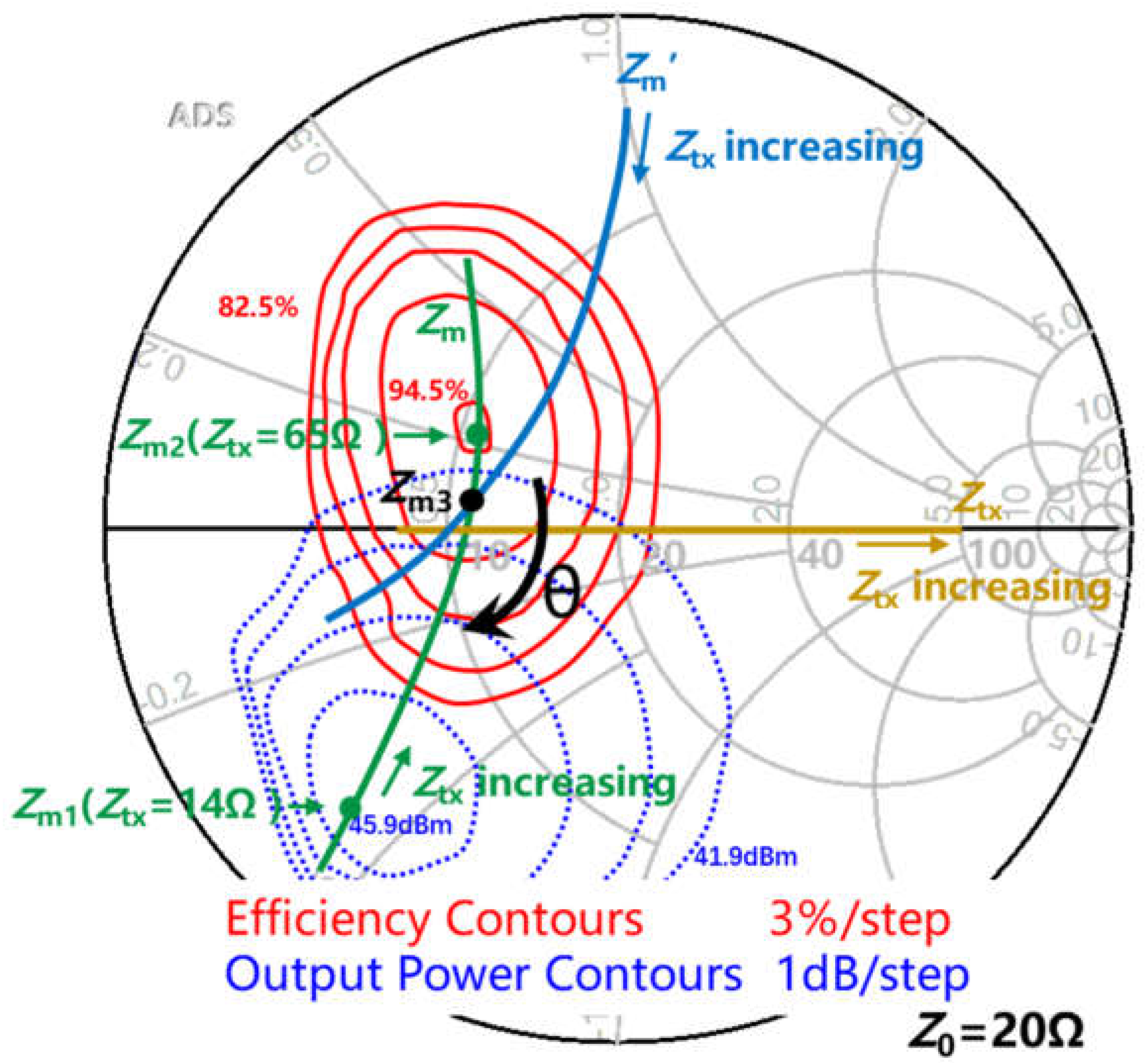
- Load-pull technique is used to identify high-efficiency Class-E PA load impedance region;
- Double-L-type IMN is used for finer impedance matching.
3.1. The Design of an L-Type IMN
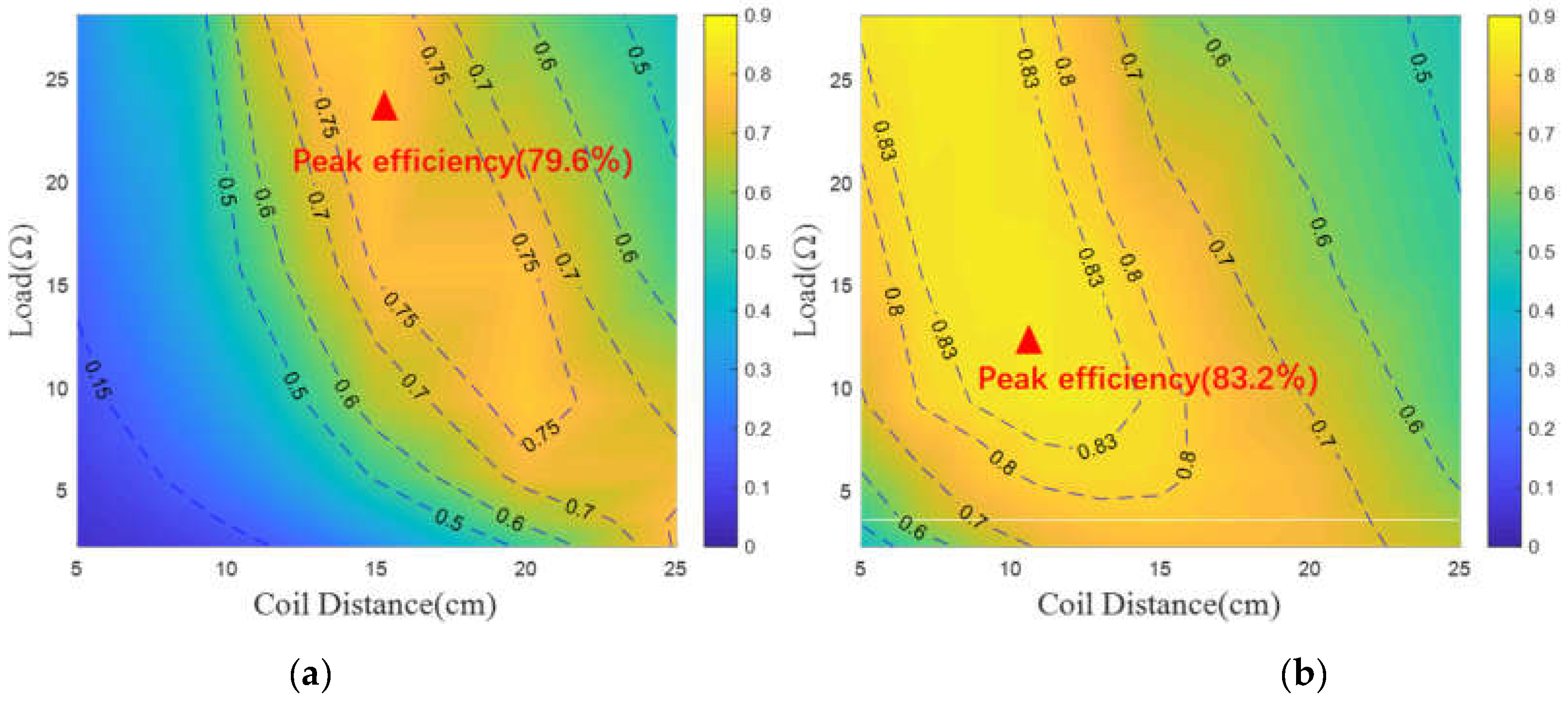
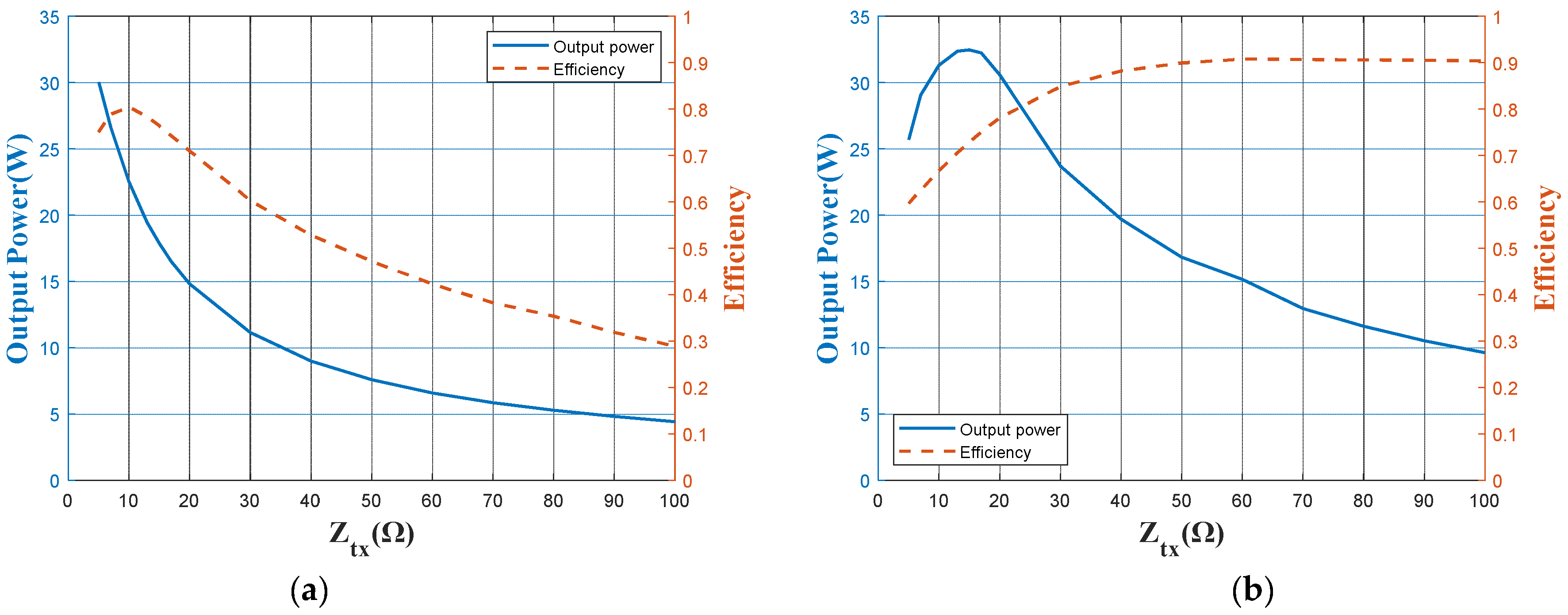
3.2. Load-Pull Technique and Doubel-L-Type IMN
3.3. Robustness of the Designed Class-E2-Based WPT System
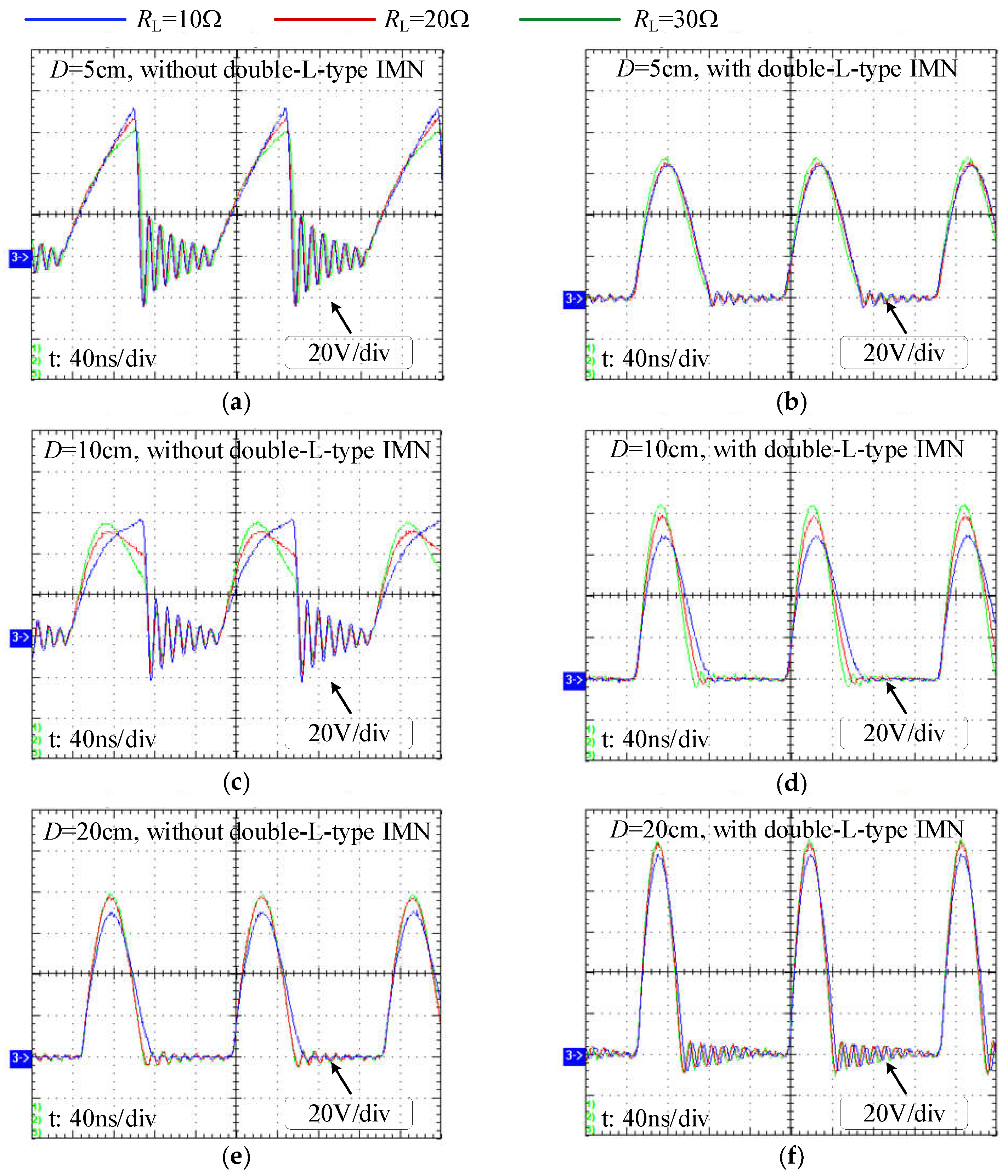
4. Experimental Verification
5. Conclusions
Author Contributions
Funding
Institutional Review Board Statement
Informed Consent Statement
Data Availability Statement
Conflicts of Interest
References
- Kurs, A.; Karalis, A.; Moffatt, R.; Joannopoulos, J.D.; Fisher, P.; Soljacic, M. Wireless power transfer via strongly coupled magnetic resonances. Science 2007, 317, 83–86. [Google Scholar] [CrossRef] [PubMed] [Green Version]
- Hui, S.Y.R.; Zhong, W.; Lee, C.K. A Critical Review of Recent Progress in Mid-Range Wireless Power Transfer. IEEE Trans. Power Electron. 2014, 29, 4500–4511. [Google Scholar] [CrossRef] [Green Version]
- Yin, H.; Fu, M.; Liu, M.; Song, J.; Ma, C. Autonomous Power Control in a Reconfigurable 6.78-MHz Multiple-Receiver Wireless Charging System. IEEE Trans. Ind. Electron. 2018, 65, 6177–6187. [Google Scholar] [CrossRef]
- Cheng, C.; Lu, F.; Zhou, Z.; Li, W.; Zhu, C.; Zhang, H.; Deng, Z.; Chen, X.; Mi, C.C. Load-Independent Wireless Power Transfer System for Multiple Loads Over a Long Distance. IEEE Trans. Power Electron. 2019, 34, 9279–9288. [Google Scholar] [CrossRef]
- Sayed, S.; Salahuddin, S.; Yablonovitch, E. Spin–orbit torque rectifier for weak RF energy harvesting. Appl. Phys. Lett. 2021, 118, 052408. [Google Scholar] [CrossRef]
- Sharma, R.; Mishra, R.; Ngo, T.; Guo, Y.X.; Fukami, S.; Sato, H.; Ohno, H.; Yang, H. Electrically connected spin-torque oscillators array for 2.4 GHz WiFi band transmission and energy harvesting. Nat. Commun. 2021, 12, 2924. [Google Scholar] [CrossRef] [PubMed]
- Fang, B.; Carpentieri, M.; Louis, S.; Tiberkevich, V.; Slavin, A.; Krivorotov, I.N.; Tomasello, R.; Giordano, A.; Jiang, H.; Cai, J.; et al. Experimental Demonstration of Spintronic Broadband Microwave Detectors and Their Capability for Powering Nanodevices. Phys. Rev. Appl. 2019, 11, 014022. [Google Scholar] [CrossRef] [Green Version]
- Nagashima, T.; Wei, X.; Bou, E.; Alarcon, E.; Kazimierczuk, M.K.; Sekiya, H. Analysis and Design of Loosely Inductive Coupled Wireless Power Transfer System Based on Class-E2 DC-DC Converter for Efficiency Enhancement. IEEE Trans. Circuits Syst. I Regul. Pap. 2015, 62, 2781–2791. [Google Scholar] [CrossRef]
- Tomoharu Nagashima, K.I.; Wei, X.; Bou, E.; Alarc’on, E.; Kazimierczuk, M.K.; Sekiya, H. Analytical design procedure for resonant inductively coupled wireless power transfer system with class-E2 DC-DC converter. In Proceedings of the IEEE International Symposium on Circuits and Systems (ISCAS), Melbourne, Australia, 1–5 June 2014; pp. 113–116. [Google Scholar]
- Kazimierczuk, M.K.; Jozwik, J. DC/DC converter with class E zero-voltage-switching inverter and class E zero-current-switching rectifier. IEEE Trans. Circuits Syst. 1989, 36, 1485–1488. [Google Scholar] [CrossRef]
- Liu, S.K.; Liu, M.; Fu, M.F.; Ma, C.B.; Zhu, X.E. A High-Efficiency Class-E Power Amplifier with Wide-Range Load in WPT Systems. In Proceedings of the 2015 IEEE Wireless Power Transfer Conference (Wptc), Boulder, CO, USA, 13–15 May 2015. [Google Scholar]
- Pinuela, M.; Yates, D.C.; Lucyszyn, S.; Mitcheson, P.D. Maximizing DC-to-Load Efficiency for Inductive Power Transfer. IEEE Trans. Power Electron. 2013, 28, 2437–2447. [Google Scholar] [CrossRef] [Green Version]
- Aldhaher, S.; Luk, P.C.-K.; Whidborne, J.F. Electronic Tuning of Misaligned Coils in Wireless Power Transfer Systems. IEEE Trans. Power Electron. 2014, 29, 5975–5982. [Google Scholar] [CrossRef] [Green Version]
- Liu, M.; Fu, M.F.; Ma, C.B. A Compact Class E Rectifier for Megahertz Wireless Power Transfer. In Proceedings of the 2015 IEEE Pels Workshop on Emerging Technologies—Wireless Power (Wow), Daejeon, Korea, 5–6 June 2015. [Google Scholar]
- Rybicki, K.; Wojciechowski, R.M. Analysis and design of a class E current-driven rectifier for 1 MHz wireless power transfer system. J. Electr. Eng. 2019, 70, 58–63. [Google Scholar] [CrossRef] [Green Version]
- Kim, N.Y. Adaptive Magnetic Resonance Wireless Power Transfer System with Optimum frequency and Power-Leve Tracking for maintaining highly efficient. In Proceedings of the International Conference on Artificial Intelligence in Information and Communication (ICAIIC), Okinawa, Japan, 11–13 February 2019; pp. 543–547. [Google Scholar]
- Assawaworrarit, S.; Fan, S. Robust and efficient wireless power transfer using a switch-mode implementation of a nonlinear parity–time symmetric circuit. Nat. Electron. 2020, 3, 273–279. [Google Scholar] [CrossRef]
- Sample, A.P.; Waters, B.H.; Wisdom, S.T.; Smith, J.R. Enabling Seamless Wireless Power Delivery in Dynamic Environments. Proc. IEEE 2013, 101, 1343–1358. [Google Scholar] [CrossRef]
- Lim, Y.; Tang, H.; Lim, S.; Park, J. An Adaptive Impedance-Matching Network Based on a Novel Capacitor Matrix for Wireless Power Transfer. IEEE Trans. Power Electron. 2014, 29, 4403–4413. [Google Scholar] [CrossRef]
- Liu, S.; Liu, M.; Han, S.; Zhu, X.; Ma, C. Tunable Class E2 DC–DC Converter with High Efficiency and Stable Output Power for 6.78-MHz Wireless Power Transfer. IEEE Trans. Power Electron. 2018, 33, 6877–6886. [Google Scholar] [CrossRef]
- Kazimierczuk, M.K.; Puczko, K. Exact Analysis of Class-E Tuned Power-Amplifier at Any Q and Switch Duty Cycle. IEEE Trans. Circuits Syst. 1987, 34, 149–159. [Google Scholar] [CrossRef]
- Kazimierczuk, M.K.; Jozwik, J. Resonant DC/DC converter with class-E inverter and class-E rectifier. IEEE Trans. Ind. Electron. 1989, 36, 468–478. [Google Scholar] [CrossRef]
- Symmetrical pi Network in Network Analysis. Available online: https://www.eeeguide.com/symmetrical-pi-network-in-network-analysis/ (accessed on 26 June 2021).


| Symbol | Value | Description | |
|---|---|---|---|
| Class-E PA | LRFC | 47 uH | RF choke inductor (MSS1583-473ME) |
| rLRFC | 0.05 Ω | ESR of LRFC | |
| Cp | 431 pF | Parallel capacitor | |
| Cr | 298 pF | Resonant capacitor | |
| Lr | 2.12 uH | Resonant inductor | |
| S | - | GaN switch(TPH3206LD) | |
| CPLD | - | Control unit for generating driving signal (EMP570T100C5N) | |
| Coupling Coils | LTX | 2.74 uH | High-Q transmitting coil, Q = 695 |
| RTX | 0.17 Ω | ESR of LTX at 6.78 MHz | |
| CTX | 201 pF | Compensation capacitor of transmitting side | |
| LRX | 2.74 uH | High-Q receiving coil, Q = 695 | |
| RRX | 0.17 Ω | ESR of LRX at 6.78 MHz | |
| CRX | Calculated by (9) | Compensation capacitor of receiving side | |
| NTX, NRX | 2, 2 | Turns of transmitting coil and receiving coil | |
| dTX, dRX | 3 mm, 3 mm | Diameter of transmitting coil wire and receiving coil wire | |
| rTX, rRX | 13 cm, 13 cm | Radius of transmitting coil and receiving coil | |
| Class-E Rectifier | Lf | 47 uH | Filter inductor (MSS1583-473ME) |
| rLf | 0.05 Ω | ESR of Lf | |
| Cf | 10 uF | Filter capacitor | |
| CD | Calculated by (4) | Diode parallel capacitor | |
| Dd | 0.5 | Duty cycle | |
| Double-L-type IMN | Lm | 470 nH | High-Q inductors, Q = 200 (2014VS-111ME, 2014VS-251ME) |
| Cmt | 1409 pF | / | |
| Lt | 916 nH | High-Q inductor, Q = 180 (2929SQ-431_E, 2929SQ-501_E) | |
| Ct2 | 470 pF | / |
| Coil Distance D | Coupling Coefficient k | DC Load RL |
|---|---|---|
| 5~25 cm | 0.027~0.267 | 5~30 Ω |
Publisher’s Note: MDPI stays neutral with regard to jurisdictional claims in published maps and institutional affiliations. |
© 2021 by the authors. Licensee MDPI, Basel, Switzerland. This article is an open access article distributed under the terms and conditions of the Creative Commons Attribution (CC BY) license (https://creativecommons.org/licenses/by/4.0/).
Share and Cite
Zhang, Y.; Feng, Y.; Liu, S.; Wu, J.; He, X. Impedance Matching Method for 6.78 MHz Class-E2-Based WPT System. Energies 2021, 14, 4289. https://doi.org/10.3390/en14144289
Zhang Y, Feng Y, Liu S, Wu J, He X. Impedance Matching Method for 6.78 MHz Class-E2-Based WPT System. Energies. 2021; 14(14):4289. https://doi.org/10.3390/en14144289
Chicago/Turabian StyleZhang, Yi, Yue Feng, Sheng Liu, Jiande Wu, and Xiangning He. 2021. "Impedance Matching Method for 6.78 MHz Class-E2-Based WPT System" Energies 14, no. 14: 4289. https://doi.org/10.3390/en14144289
APA StyleZhang, Y., Feng, Y., Liu, S., Wu, J., & He, X. (2021). Impedance Matching Method for 6.78 MHz Class-E2-Based WPT System. Energies, 14(14), 4289. https://doi.org/10.3390/en14144289