Article

Fabrication and Performance Evaluation of Cold Thermal Energy Storage Tanks Operating in Water Chiller Air Conditioning System

Department of Renewable Energy, HCMC University of Technology and Education, Ho Chi Minh City 700000, Vietnam
Energies 2021, 14(14), 4159; https://doi.org/10.3390/en14144159
Submission received: 13 May 2021 / Revised: 20 June 2021 / Accepted: 1 July 2021 / Published: 9 July 2021
(This article belongs to the Section D: Energy Storage and Application)

Abstract

:
In this study, cold and thermal storage systems were designed and manufactured to operate in combination with the water chiller air-conditioning system of 105.5 kW capacity, with the aim of reducing operating costs and maximizing energy efficiency. The cold storage tank used a mixture of water and 10 wt.% glycerin as a phase-change material (PCM), while water was used as heat transfer fluid (HTF). The cold storage heat exchanger was made of polyvinyl chloride (PVC). On the other hand, the thermal storage tank used water as the storage fluid with a capacity of 50 L of hot water per hour. The thermal storage did not use a pump for water transfer through the heat exchanger, so as to save energy and operating costs. In this paper, the operating parameters of the cold and thermal storage tanks are shown according to the results of experimental research, including the temperatures of cooling and heating load, heat transfer fluid, and cold storage material during the discharge process, as well as the discharge duration. The system assisted the air conditioner in cooling the internship workshop space at the university with an area of 400 m2, contributing to a remarkable reduction in air-conditioning system operating costs during the daytime. Furthermore, the system recovered waste heat from the compressor of the water chiller, and a thermal storage system was successfully built and operated, providing 50 L of hot water at a temperature of 60 °C per hour to serve the everyday needs of school students. This design was suitable for the joint operation of cold and thermal storage tanks and the water chiller air-conditioning system for cooling and heating applications.

Graphical Abstract

1. Introduction

Cold and thermal energy storage technology is one of the most effective methods with which to solve the problems of energy shortage and environmental pollution all over the world. Cold and thermal energy storage systems have been proposed in the energy-saving field for a long time by many scientists. A cold storage system involving direct contact between cold water and a PCM was proposed by Martin et al. [1], who investigated the application of phase transition to cold storage. The model used a sensible heat storage method, whereby the refrigerant was in direct contact with the PCM. The study showed that cold storage at peak hours with high electricity prices would greatly impact cost; thus, this technology could reduce peak load during on-peak periods by shifting to off-peak operation.
Benjamin et al. [2] introduced a storage system combining seasonal ice storage, whereby ice was stored during winter when the temperature was low. In the summer, the preserved ice would be extracted for refrigeration, and the melted ice was used as a chiller for cool water storage. During periods of low load, the storage system would implement the chiller water to run the system. This new technology combining PCM and ice storage was applied to an air-conditioning system. Wang et al. [3] investigated PCMs and identified a new material for combination with ice storage technology. Furthermore, they conducted simulations and experiments describing the defrosting process of the cold storage system for application to an air-conditioning system. This study illustrated the impact of temperature on the heat transfer of fluid streams. Xie et al. [4] studied ice storage methods. The overall heat transfer coefficient during cold storage was calculated and analyzed using different heat exchangers. The results showed that the cold storage efficiency greatly improved upon adding a heat exchanger. The combination of ice storage and a PCM improved the efficiency of the air-conditioning system. Zhai et al. [5] studied phase-change temperature and cold storage density, showing that most of the PCM in the ice storage system had low dispersion. Ethylene glycol and propylene glycol could be used as cold storage agents in the future. Cheng et al. [6] proposed an ice storage method to store energy at low temperatures, using various PCMs. The heat exchange process was simulated, along with a calculation of cold storage ratio and density.
Melone et al. [7] applied PCMs for cold storage. The experimental materials proved their ability to maintain internal temperature 10 times longer than cellulose of similar thickness (2 cm). Vitorino et al. [8] studied an aqueous graphite solution with a stable shape by adding collagen as a PCM for better heat conductivity during ice storage. The research showed that thermal conductivity was doubled upon adding ~20% graphite. Murphy et al. assessed the benefits of ice storage control optimization and management [9], focusing on the controller used for a specific ice cube, with an evaporator placed inside the storage tank. The water was circulated through the tank along with stored energy from the evaporator. Pu et al. [10] evaluated cold storage methods and their efficiency upon incorporating ice-water storage systems. The system used a latent heat storage method. This study also proposed cold storage technology for air-conditioning systems, mentioning problems related to energy consumption at peak loads and adjusting the processes accordingly. In addition, the accumulated storage consumption of total power at peak hours was found to increase with adoption of the system.
Wang et al. and Lee et al. [11,12] evaluated the efficiency of PCMs and refrigerants incorporated in ice storage technology in buildings. Through the research, the authors proposed cold storage accumulation using water/ice refrigerant as the PCM. Furthermore, the efficiency of the aforementioned cold storage method was verified through experiments and computer simulations. Water was identified as a refrigerant capable of energy storage, with the results indicating that water/ice could be a promising phase-change material due to its high latent heat density.
In addition to the application of cold storage technology in air-conditioning systems, it is necessary to research and develop methods for waste heat recovery to save energy and protect the environment. Heat pumps have effectively used industrial wastewater and waste heat from urban wastewater as heat sources, which can be used for heating activities in residential, communal, and administrative buildings in cities [13]. Domestic wastewater is often discharged at high temperatures, as more than 60% of sewage from buildings originates from bathtubs, sinks, dishwashers, and washing machines. This heat running to sewage systems can be reused, with wastewater becoming a heat carrier, to generate clean and renewable heat energy, through heat exchangers and heat pumps for the conditioning and heating of buildings. The use of a heat pump system to utilize waste heat from public bathrooms in colleges and universities was also examined in the past, highlighting that bathrooms can become a suitable waste heat source for apt water flow, temperature, and quality, with remarkable benefits of saving energy and pollution reduction [14,15].
Wastewater heat recovery applications are becoming prevalent regarding energy consumption efficiency. Sustainable energy sources and low emissions during air conditioning and heating can be achieved by collecting energy in wastewater through specially designed heat exchangers called heat pumps for wastewater reuse. These systems make use of the heat energy from wastewater discharge to reheat consumers’ household water sources [16]. Heat pump systems are becoming more widespread and are an inseparable component of environmentally friendly energy-saving technology; they have been widely applied in northern European countries for many years. Wastewater is seen as a renewable heat source for heat pumps, with such systems becoming more popular due to their advantages of relatively higher energy efficiency and environmental protection [17].
In this study, ice and thermal storage systems were designed and manufactured to operate in combination with the water chiller air-conditioning system of 105.5 kW capacity. The systems were placed in an internship workshop at the university. The ice storage discharge during the day was used for conditioning of the students’ study space, while the thermal storage provided hot water with a capacity of 50 L/h for domestic activities. Experiments were carried out to evaluate the performance of the cold and thermal storage systems, acting as a basis for expanding the application of the system models to air conditioning and other fields.

2. Methodology

2.1. Mathematical Equations

In this section, we calculate the parameters of the cold and thermal energy storage tanks. The equations used to calculate the heat transfer surface area of heat exchangers in the tanks are presented below [18,19].
The mean temperature of the heat transfer fluid is expressed as
t a v e = 0.5 ( t + t )
Considering the properties of saturated liquid at tave, we obtain
ρ 1 , C p 1 , λ 1 , v 1 ; Pr 1 = v 1 a = µ C p 1 λ 1 ,
where a = λ 1 ρ 1 × C p 1 is the thermal diffusivity (m2/s).
The mass flow rate of heat transfer fluid is expressed as
G = Q C p 1 × Δ t
The Reynolds number can be calculated as follows:
Re f 1 = ϖ 1 × d 1 v 1
The Nusselt number can be calculated as follows:
N u f 1 = C × ( Re f 1 ) m × ( Pr 1 ) n ( Pr 1 Pr s ) 0.25 ,
where C, m, and n are constants that depend on Re and Pr [20]. Thus, the convection heat transfer coefficient of heat transfer fluid is expressed as
h 1 = N u f 1 × λ 1 d 1
The mean temperature of cold storage material is expressed as
T m = 0.5 × ( t s 2 + t f 2 )
Considering the properties of cold storage material in saturation, we obtain
ρ 2 ; C p 2 ; λ 2 , v 2 , Pr 2 .
The Grashoft number can be calculated as follows:
G r 2 = g . β 2 . d 3 2 t v w a t e r 2 .
The Rayleigh number can be calculated as follows:
R a 2 = ( G r 2 . Pr 2 )
The Nusselt number can be calculated as follows:
N u 2 = C . R a 2 n
Thus, the convection heat transfer coefficient of cold storage material is expressed as
h 2 = N u 2 × λ 2 d 2
Accordingly, the overall heat transfer coefficient is expressed as
U = 1 1 d 1 . h 1 + 1 2 λ ln d 2 d 1 + 1 d 2 . h 2
The logarithmic mean temperature difference can be calculated as follows:
Δ T L M = Δ t m a x Δ t m i n ln Δ t m a x Δ t m i n
Lastly, the heat transfer surface area can be calculated as follows:
F = Q U × Δ T L M

2.2. Model Design

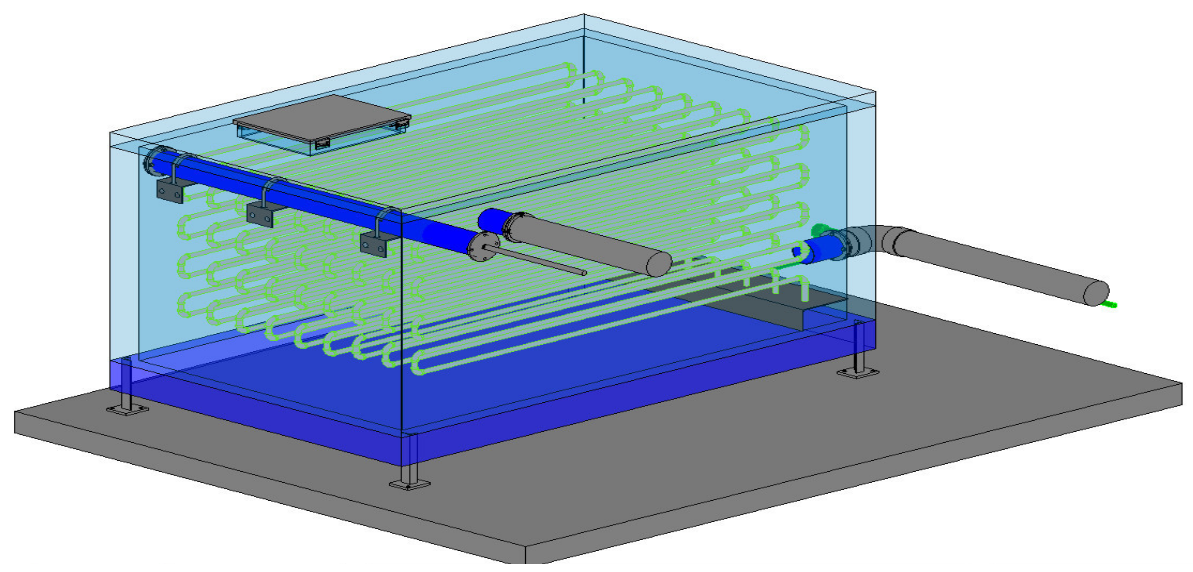
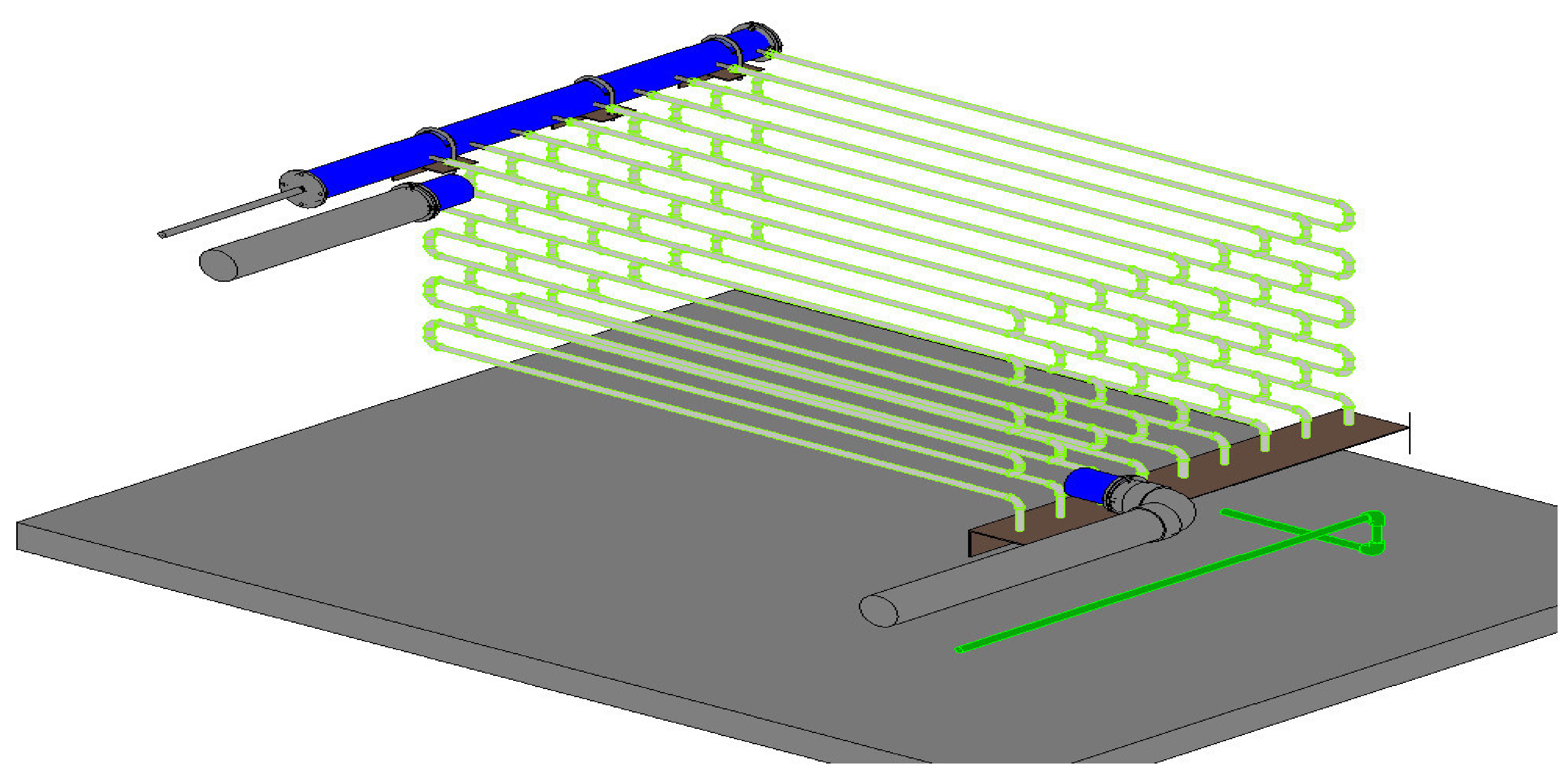
2.2.1. Cold Storage Tank

The cold storage tank was designed with the dimensions of 2950 mm × 1800 mm × 1480 mm (length × width × height). Inside the cold storage tank, there was a heat exchanger composed of 81 PVC tubes divided into nine rows, each with nine tubes. These rows of tubes were gathered at the upper manifold for the inlet and at the lower manifold for the outlet. The upper manifold was 150 mm in diameter and 1480 mm in length, and it was used to evenly distribute the flow of water (heat transfer fluid) charged from the fan coil units (FCUs) to the heat exchanger in the cold storage tank. The 300 mm × 150 mm × 1480 mm lower manifold was used to concentrate the heat transfer fluid from the heat exchanger, before distributing it to the FCUs. The cold storage tank was heat-insulated with glass wool and foam. The insulation for the tank wall was 100 mm thick, while that for the tank bottom was 200 mm thick. The heat exchanger inside the tank was made up of 21 mm diameter polyvinyl chloride (PVC) tubes. The gaps between tube centers were 200 mm horizontally and 135 mm vertically, providing enough space for liquid to exchange heat in a flexible manner with the plastic tubes, while also increasing heat exchange efficiency as a function of the consistent contact space between tube rows. The 3D design model of the cold storage tank is shown in Figure 1. Figure 2 illustrates the heat exchanger inside the cold storage tank.

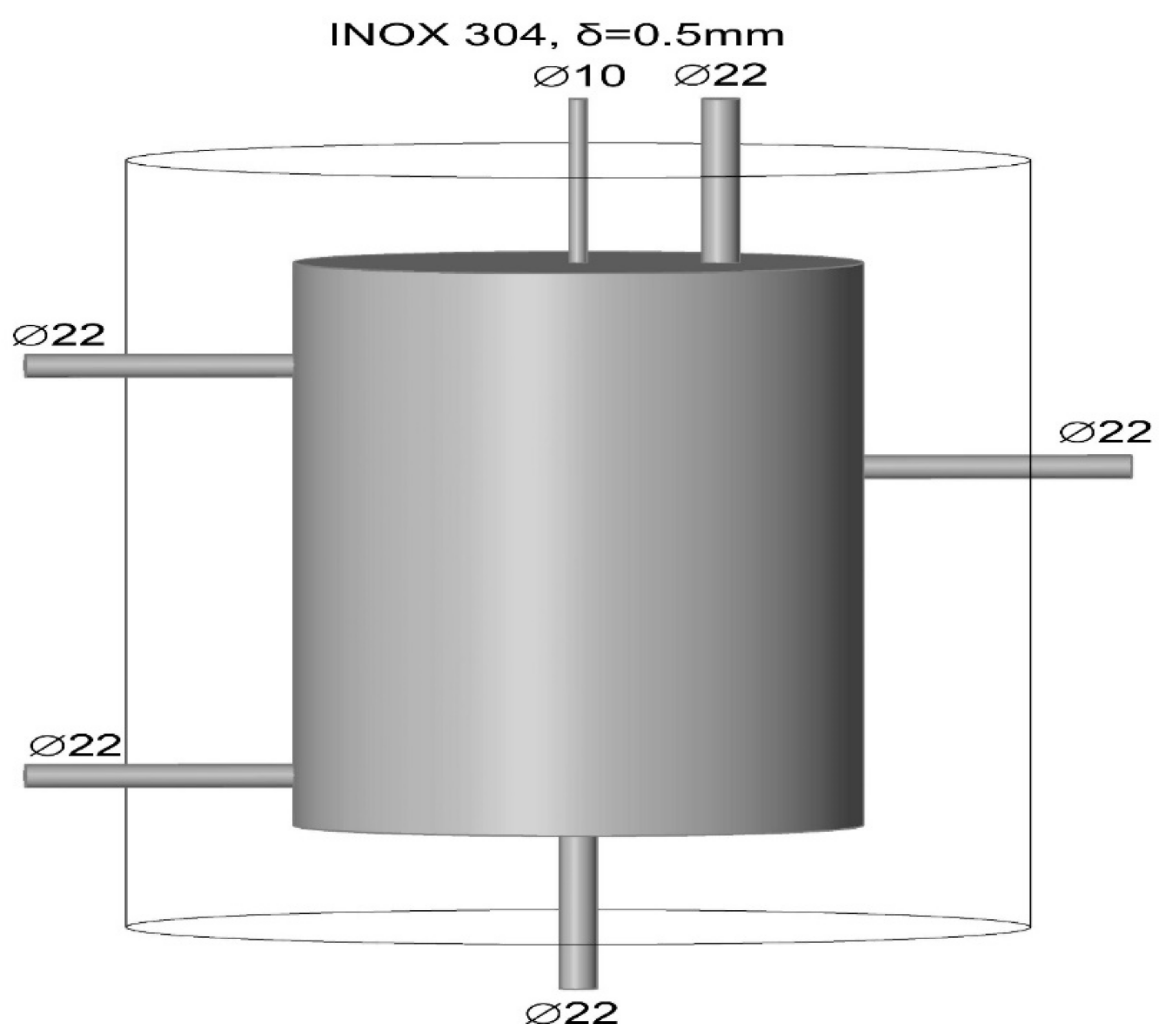
2.2.2. Thermal Storage Tank

The thermal storage tank had a capacity of 50 L and was made of 304 stainless steel. Its dimensions were 550 mm in height, 170 mm in radius, and 5 mm in thickness. The outside of the tank was covered with an insulating foam layer of 100 mm thickness to avoid heat loss and maintain durability. The design of the thermal storage tank is illustrated in Figure 3, where it can be seen that there were two tubes on the left side of the storage tank (one upper and one lower) with a diameter of 22 mm, connecting the two inlets of the heat exchanger tube embedded in the compressor’s rotor. One tube of 22 mm diameter at the tank bottom was connected to a blow-down valve. Another tube of 22 mm diameter on the right side of the tank was connected to the hot water supply. At the top of the tank, there was a tube of 10 mm diameter used to discharge air and a tube of 22 mm diameter used to supplement cold water in the case of water shortage in the tank.

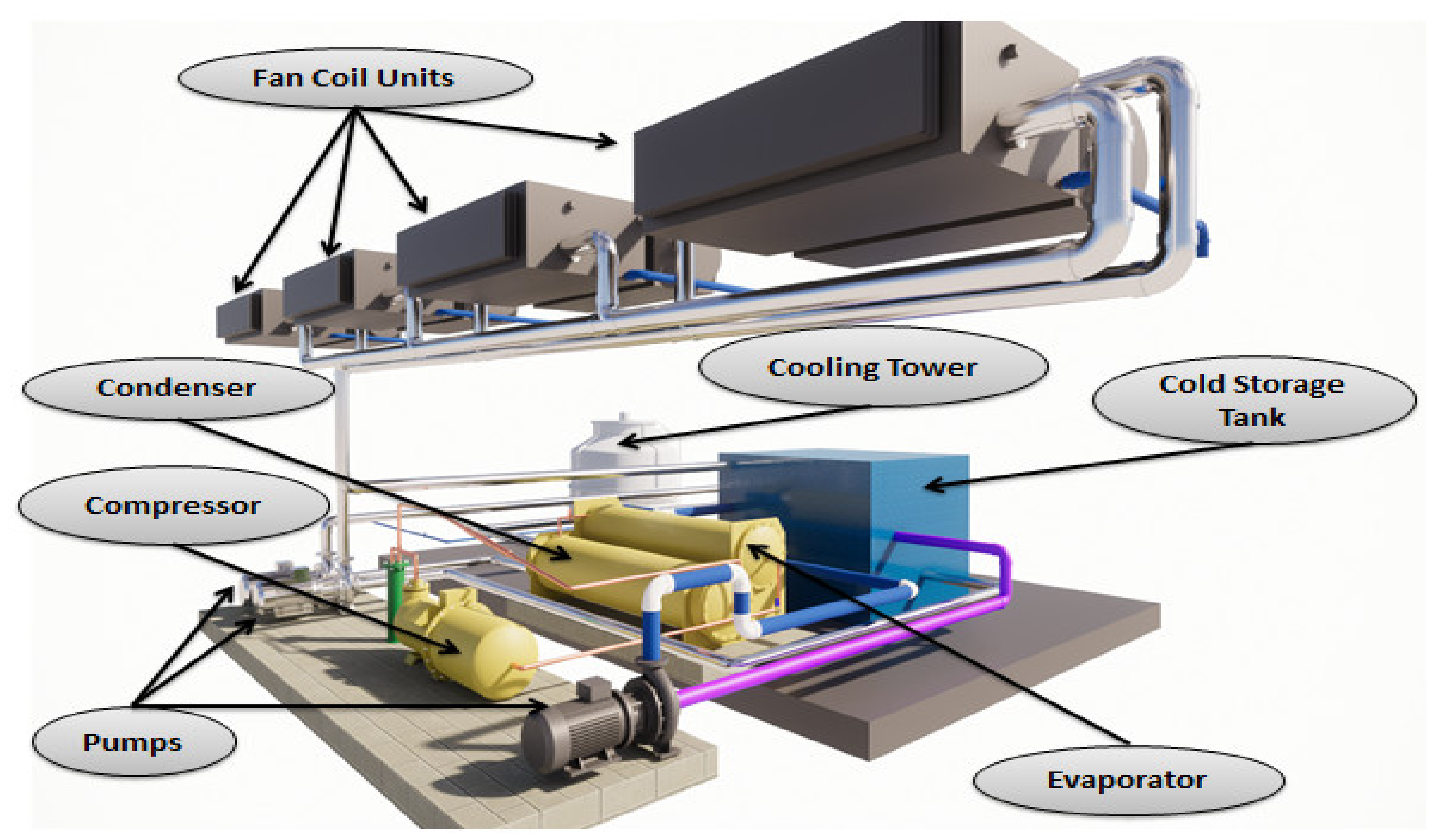
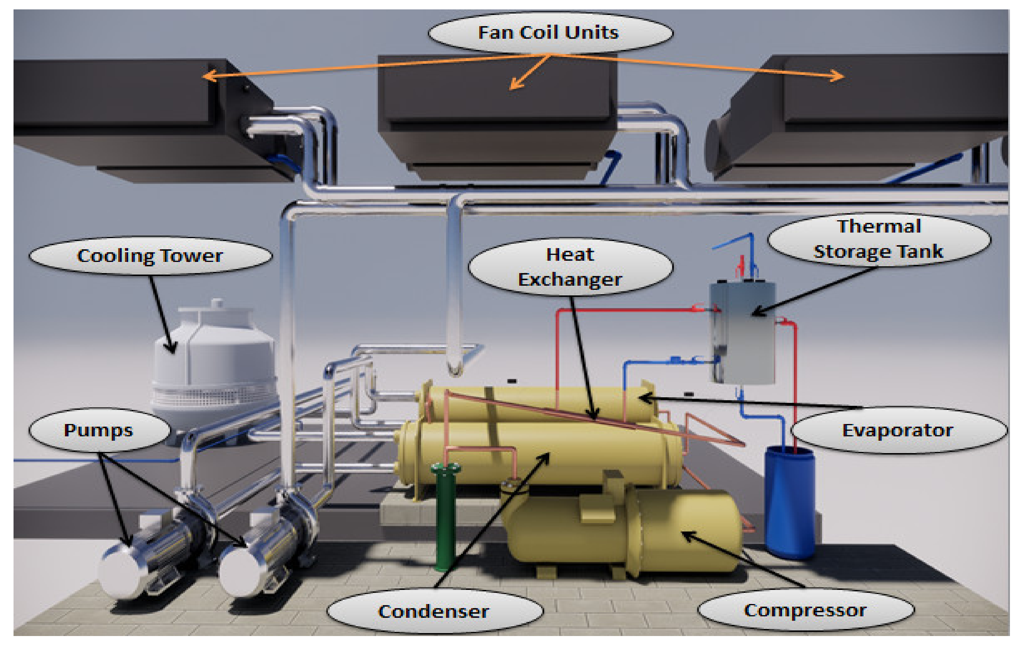
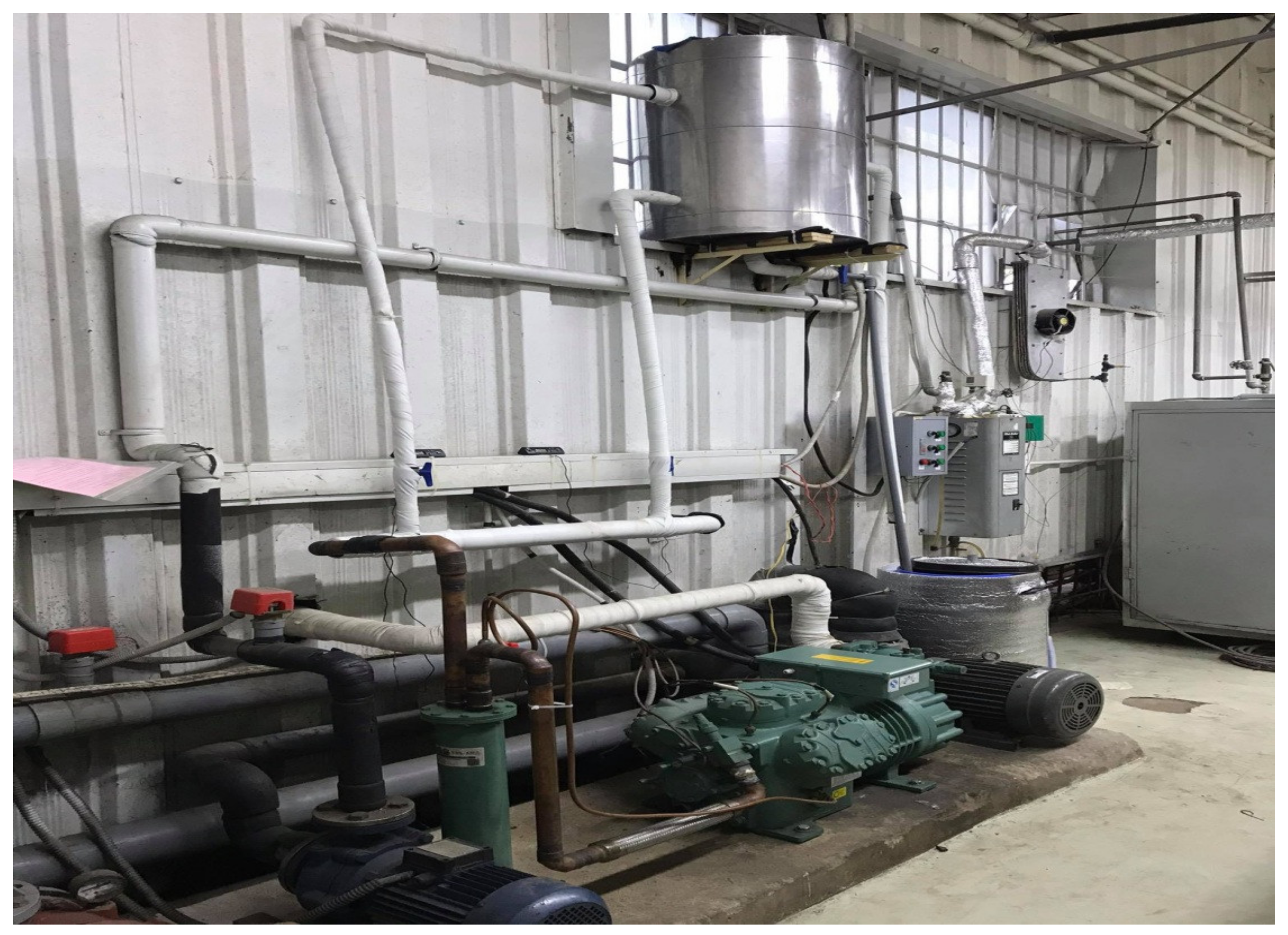
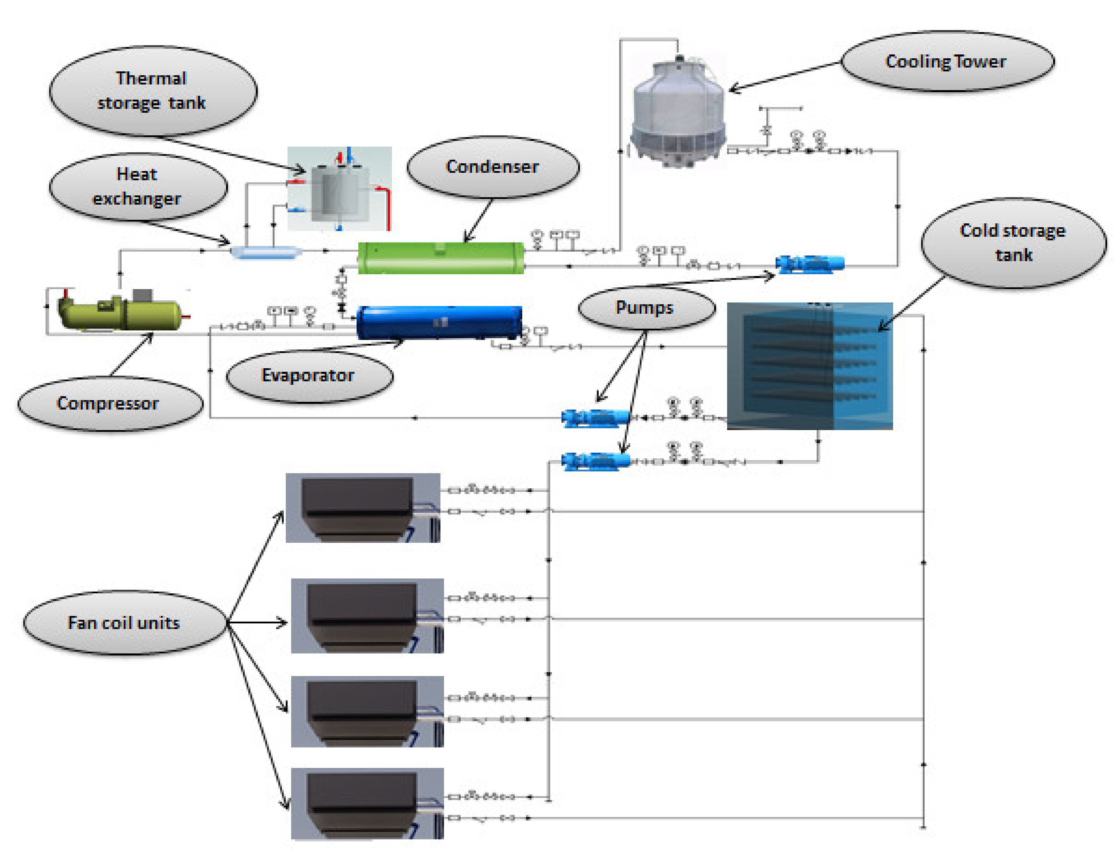
2.2.3. System Installation

Figure 4 shows the installation diagram of the water chiller air-conditioning system combined with cold storage. In this study, a mixture of water with 10 wt.% glycerin was used as the cold storage material, while water was used as the heat transfer fluid. Glycerin was used as PCM because this material has many advantages such as nontoxicity, low freezing temperature, wide phase-change temperature range, high phase-change latent heat, miscibility with water, and ease of use. The water chiller system was operated to cool the cold storage material to −3 °C, after which it stopped operating, thereby initiating the cooling discharge system for air conditioning. Figure 5 illustrates the cold storage tank integrated into the water chiller air-conditioning system.
Figure 6 shows the installation diagram of the water chiller air-conditioning system combined with thermal storage. In this study, water was used as the heat transfer fluid and thermal storage material. A double-pipe heat exchanger was installed in the discharge line of the compressor in the water chiller air-conditioning system to recover waste heat from the high-temperature refrigerant. The water chiller system was operated in parallel with the thermal storage system. Cold water is naturally circulated into the double-pipe heat exchanger, which was installed in the discharge line of the compressor, to recover waste heat. The high-temperature refrigerant warmed water to 60 °C. Figure 7 illustrates the thermal storage tank integrated into the water chiller air-conditioning system. Figure 8 shows a schematic diagram of the water chiller air-conditioning system combined with both cold and thermal storage.

2.2.4. Experimental Setup

The testing system was implemented in two steps. Firstly, the water chiller system was operated to charge the cold and thermal load. Secondly, the water chiller system was stopped to implement the discharging process. In this work, the cold storage tank used a mixture of water and 10 wt.% glycerin as a phase-change material (PCM) for cold storage, while water was used as heat transfer fluid (HTF). In the water chiller operating mode, the temperature sensors were assembled at the top, middle, and bottom of the cold and thermal storage tanks to investigate the changes in cold and thermal storage material temperature during the charging and discharging process. Upon attaining the cold storage temperature, the water chiller was stopped to operate the cold storage tank. The temperature sensors were assembled in front of the FCU blower doors to investigate the changes in air temperature leaving the FCU during the discharging process. Two temperature sensors were set to record the temperature values of the inlet and outlet water of the cold storage tank. T-type thermometers (DS-1, Youkong, China) were used to record temperature values. A schematic illustration of the experimental system of the water chiller air-conditioning system integrated with cold and thermal storage tanks is shown in Figure 9.

3. Results and Discussion

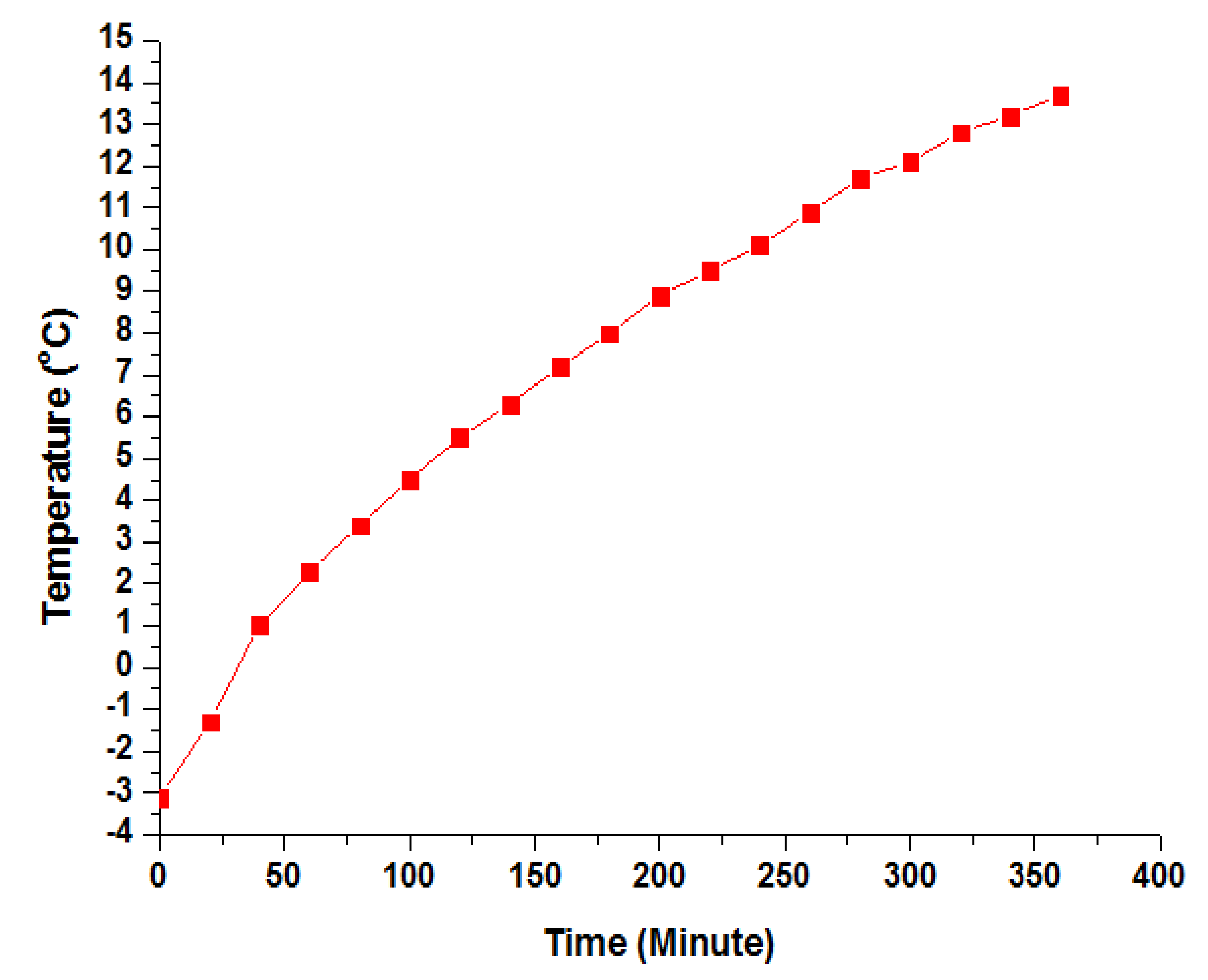
3.1. Changes in Cold Storage Material Temperature during Charging Process

Figure 10 shows the changes in cold storage material temperature over time. The results show that the cold storage material temperature in the storage tank was originally 29.9 °C. After 20 min of loading, the temperature decreased from 29.9 °C to 28.4 °C, while the stored energy in the tank gradually increased. After 120 min of operating the system, the cold storage material temperature dropped to 19.6 °C. Further examination revealed that the cold storage material temperature tended to decrease over time because the heat exchange in the evaporator was stable, whereas the tank coverage prevented thermal transfer to the environment. After 420 min of operating the system, the cold storage material temperature in the tank was −3.1 °C. As shown in Figure 10, the cold storage material temperature in the tank steadily decreased over time, with an average decrease of 1 °C/12.7 min.

3.2. Changes in Temperatures of Heat Transfer Fluid and Cold Storage Material during Discharging Process

Figure 11 illustrates the changes in water (heat transfer fluid) temperature entering and leaving the heat exchanger during the discharging process. The temperature of water (heat transfer fluid) before the fan coil unit (FCU) operation was 9.8 °C and 13.8 °C in the lower and upper manifolds, respectively. During the charging process of the water (heat transfer fluid) in the heat exchanger and the two manifolds, heat exchange was performed, which caused the refrigerant temperature to drop. After 20 min of discharging, the water (heat transfer fluid) temperature entering and exiting the heat exchanger was slightly increased. The temperature of water (heat transfer fluid) passing through the lower manifold was 12.3 °C, and while that passing from the FCU to the upper manifold was 16.4 °C. Thus, the temperature gap between incoming and outgoing heat transfer fluid in the FCU was 4.1 °C. The heat transfer fluid entering FCUs and undergoing heat exchange led to an increase in heat transfer fluid temperature. Accordingly, after 220 min of discharging, the heat transfer fluid temperature from the lower manifold was 14.5 °C, while that from the FCU to the upper manifold was 17.8 °C. The temperature gap between the FCU inlet and outlet heat transfer fluid was 3.3 °C. After 360 min, the heat transfer fluid temperature coming out of the lower manifold was 15.5 °C, while that from the FCU to the upper manifold was 18.6 °C. The temperature gap between the FCU inlet and outlet heat transfer fluid was 3.1 °C. The temperature gaps tended to decrease over time because the cold storage material temperature in the tank increased during the discharging process through heat exchanged with the heat transfer fluid tube. As shown in Figure 12, at the beginning of discharge, the cold storage material temperature was −3.1 °C. After 360 min, the cold storage material temperature was 13.7 °C, whereas the input and output temperatures of the heat exchanger were 15.5 °C and 18.6 °C, respectively. The average increase in cold storage material temperature in the tank during discharging was 1 °C/21.4 min.

3.3. Changes in Air Temperature Leaving the FCU during Discharging Process

After 7 h of charging, discharge was performed. The water (heat transfer fluid) was pumped through the heat exchanger, thereby reducing the temperature. The low-temperature water was then distributed to four FCUs with a total capacity of 25 kW placed in an area of 400 m2. When discharging began, the room temperature was 32 °C. After 20 min, the air leaving the FCU was 16.5 °C, and the room temperature dropped to 28 °C. After 40 min, the air leaving the FCU was 19 °C, and the room temperature dropped to 27 °C. After 360 min, the temperature of the air leaving the FCU increased slightly before remaining at 21 °C, and the room temperature stabilized at 26 °C. The temperature of the workshop space was maintained between 25 °C and 28 °C. The changes in the temperature of air leaving the FCU are shown in Figure 13. At our university, the price of electricity can be divided into three time frames, ranging from 0.041 USD/kWh to 0.12 USD/kWh. In low-price periods, the water chiller system was operated to charge the load for the cold storage tank, thereby reducing its operation cost.

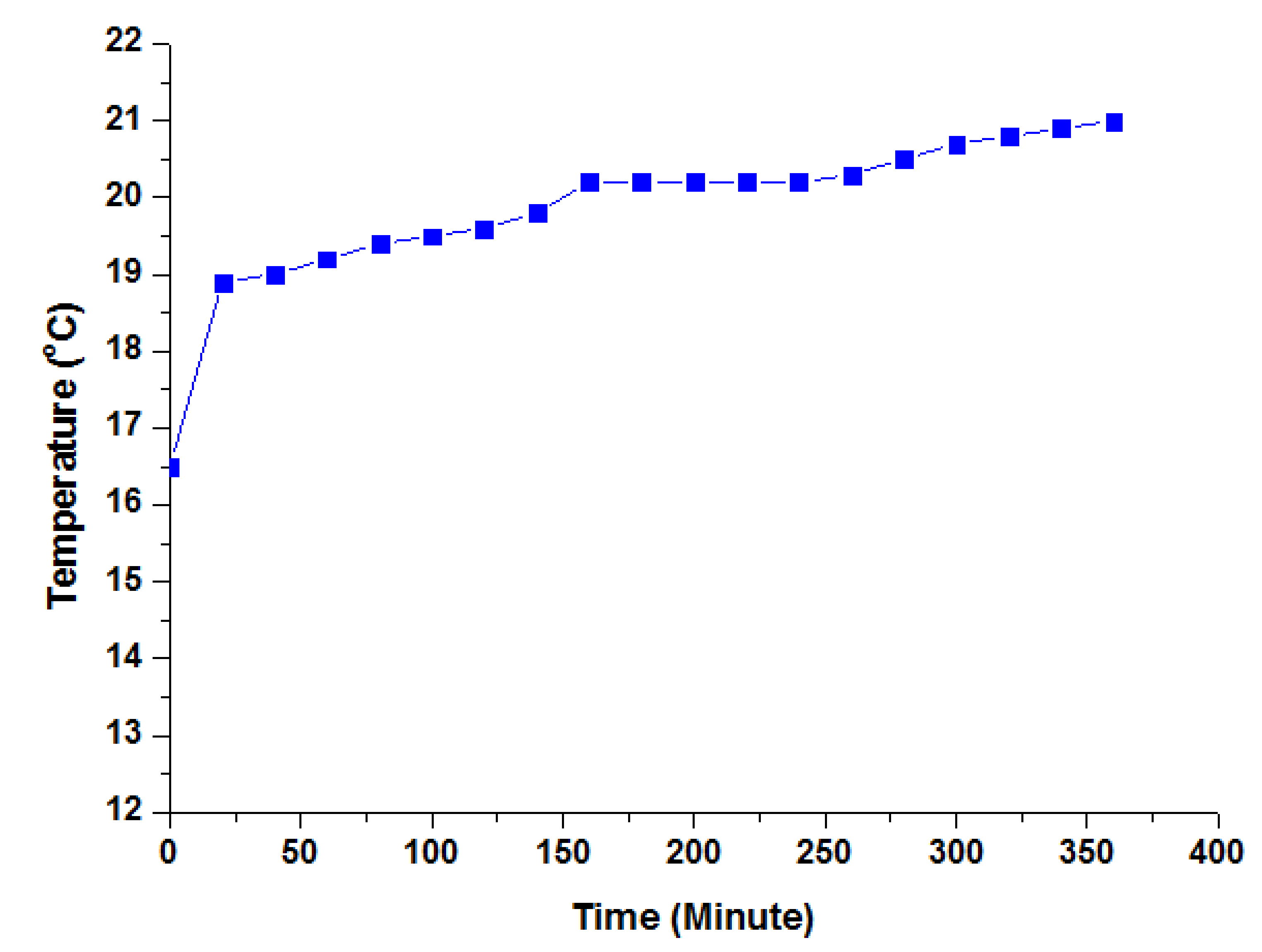
3.4. The Temperature Changes of Water in the Thermal Storage Tank

As shown in Figure 14, the water temperature varied as a function of its position in the storage tank. The temperature curve for the region between the middle and bottom of the tank differed slightly in the first 20 min. From this point until 40 min, the temperature increased from 34.6 °C to 56.6 °C, coming close to the temperature at the bottom of the tank (60.8 °C). The equivalent results are shown for the top of the tank. Despite large discrepancies within the 25 min, the two curves converged by 40 min. From 40–60 min, all three curves were relatively similar and the differences were quite trivial, whereas the temperature at the bottom of the tank increased from 60 min onward.

4. Conclusions

In this study, cold and thermal storage systems were designed, fabricated, and operated in conjunction with the water chiller air-conditioning system. A thorough analysis of experiments and simulations yielded the following conclusions:
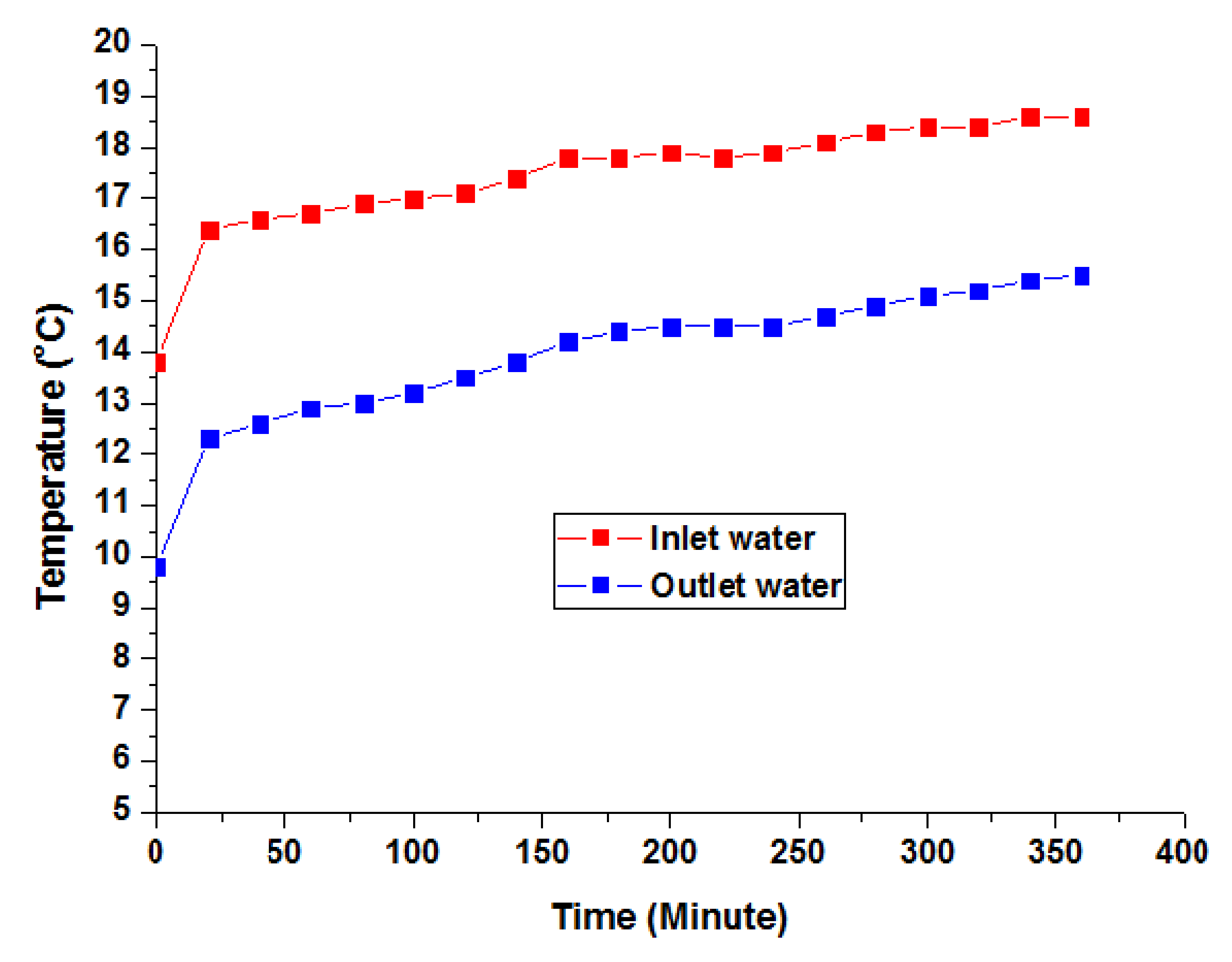
  • The heat transfer process in the heat exchanger of the cold storage tank was acceptable. The temperature difference of heat transfer fluid between the inlet and outlet of the heat exchanger ranged from 3 °C to 4 °C.
  • A cold storage system was successfully fabricated and operated, assisting the air conditioner in cooling the internship workshop space at the university with an area of 400 m2, thereby contributing to a remarkable reduction in operating costs during the daytime.
  • To recover the waste heat from the compressor of the water chiller, a thermal storage system was successfully built and operated, providing 50 L of hot water at a temperature of 60 °C per hour to serve the everyday needs of school students. The aim of this study was to design and produce a waste heat recovery thermal storage system to save energy, reduce operating costs, and mitigate environmental pollution. Therefore, further research and development of the thermal storage system are essential for it to become increasingly applicable.

Funding

The author would like to thank the Vietnam Ministry of Education and Training (Project No. B2019-SPK-02; Contract No. 02/HĐKHCN) for the financial support.

Institutional Review Board Statement

Not applicable.

Informed Consent Statement

Not applicable.

Data Availability Statement

Not applicable.

Acknowledgments

The author would like to thank the Vietnam Ministry of Education and Training (Project No. B2019-SPK-02; Contract No. 02/HĐKHCN) for the financial support.

Conflicts of Interest

The authors declare no conflict of interest.

Nomenclature

CpSpecific heat at constant pressure (kJ·kg−1·K−1)
FHeat transfer surface area (m2)
hConvection heat transfer coefficient (W·m−2 K−1)
MMass flow rate (g·s−1)
pPressure (Pa)
QHeat transfer rate (W)
TTemperature (K)
UOverall heat transfer coefficient (W·m−2·K−1)
ΔTLMLogarithmic mean temperature difference (K)
λThermal conductivity (W·m−2.K)
aThermal diffusivity (m2/s)
ReReynolds number
PrPrandtl number
PrsPrandtl number at surface
NuNusselt number
RaRayleigh number
GrGrashof number
CCoefficient
mExponent of Reynolds number
nExponent of Prandtl number
βVolumetric coefficient of expansion (K−1)
ρ Density (kg.m−3)
μViscosity (N.s.m−2)
νKinematic viscosity (m2.s−1)
tHeat transfer fluid inlet temperature
t’’Heat transfer fluid outlet temperature
ts2Outer surface temperature of pipe
tf2Cold storage material temperature
d1Inner diameter (mm)
d2Outer diameter (mm)

References

  1. Martin, V.; He, B.; Setterwall, F. Direct contact PCM–water cold storage. Appl. Energy 2010, 87, 2652–2659. [Google Scholar] [CrossRef]
  2. Ruddell, B.L.; Salamanca, F.; Mahalov, A. Reducing a semiarid city’s peak electrical demand using distributed cold thermal energy storage. Appl. Energy 2014, 134, 35–44. [Google Scholar] [CrossRef]
  3. Wang, X.; Dennis, M. Characterisation of thermal properties and charging performance of semi-clathrate hydrates for cold storage applications. Appl. Energy 2016, 167, 59–69. [Google Scholar] [CrossRef]
  4. Xie, Y.; Li, G.; Liu, D.; Liu, N.; Qi, Y.; Liang, D.; Guo, K.; Fan, S. Experimental study on a small scale of gas hydrate cold storage apparatus. Appl. Energy 2010, 87, 3340–3346. [Google Scholar] [CrossRef]
  5. Zhai, X.Q.; Wang, X.L.; Wang, T.; Wang, R.Z. A review on phase change cold storage in air-conditioning system: Materials and applycation. Renew. Sustain. Energy Rev. 2013, 22, 108–120. [Google Scholar] [CrossRef]
  6. Cheng, X.; Zhai, X. Thermal performance analysis and optimization of a cascaded packed bed cool thermal energy storage unit using multiple phase change materials. Appl. Energy 2018, 215, 566–576. [Google Scholar] [CrossRef]
  7. Melone, L.; Altomare, L.; Cigada, A.; De Nardo, L. Phase change material cellulosic composites for the cold storage of perishable products: From material preparation to computational evaluation. Appl. Energy 2012, 89, 339–346. [Google Scholar] [CrossRef]
  8. Vitorino, N.; Abrantes, J.C.; Frade, J.R. Gelled graphite/gelatin composites for latent heat cold storage. Appl. Energy 2013, 104, 890–897. [Google Scholar] [CrossRef]
  9. Murphy, M.D.; O’Mahony, M.J.; Upton, J. Comparison of control systems for the optimisation of ice storage in a dynamic real time electricity pricing environment. Appl. Energy 2015, 149, 392–403. [Google Scholar] [CrossRef]
  10. Pu, J.; Liu, G.; Feng, X. Cumulative exergy analysis of ice thermal storage air conditioning system. Appl. Energy 2012, 93, 564–569. [Google Scholar] [CrossRef]
  11. Wang, C.; He, Z.; Li, H.; Wennerstern, R.; Sun, Q. Evaluation on performance of a phase change material based cold storage house. Energy Procedia 2017, 105, 3947–3952. [Google Scholar] [CrossRef]
  12. Lee, W.S.; Chen, Y.T.; Wu, T.H. Optimization for ice-storage air conditioning system using particle swarm algorithm. Appl. Energy 2009, 86, 1589–1595. [Google Scholar] [CrossRef]
  13. Alekseiko, L.N.; Slesarenko, V.V.; Yudakov, A.A. Combination of wastewater treatment plants and heat pumps. Pac. Sci. Rev. 2014, 16, 36–39. [Google Scholar] [CrossRef] [Green Version]
  14. Cipolla, S.S.; Maglionico, M. Heat recovery from urban wastewater: Analysis of the variability of flow rate and temperature in the sewer of Bologna, Italy. Energy Procedia 2014, 45, 288–297. [Google Scholar] [CrossRef] [Green Version]
  15. Zhang, Q.; Fan, X.; Zhang, W.; Wang, Z. Utilization Potential and Economic Feasibility Analysis of Bathing Sewage and its Heat Generated in Colleges and Universities. Energy Procedia 2017, 142, 1244–1250. [Google Scholar] [CrossRef]
  16. Culha, O.; Gunerhan, H.; Biyik, E.; Ekren, O.; Hepbasli, A. Heat exchanger applications in wastewater source heat pumps for buildings: A key review. Energy Build. 2015, 104, 215–232. [Google Scholar] [CrossRef]
  17. Hepbasli, A.; Biyik, E.; Ekren, O.; Gunerhan, H.; Araz, M. A key review of wastewater source heat pump (WWSHP) systems. Energy Convers. Manag. 2014, 88, 700–722. [Google Scholar] [CrossRef]
  18. Thulukkanam, K. Heat Exchanger Design Handbook, 2nd ed.; CRC Press Taylor & Francis Group: Boca Raton, FL, USA, 2013. [Google Scholar]
  19. Kutz, M. Heat Transfer Calculations; MCGraw-Hill: New York, NY, USA, 2005. [Google Scholar]
  20. Turns, S.R. Thermal Fluid Sciences: An Intergrated Approach; Cambridge University Press: Cambridge, UK, 2006. [Google Scholar]
Figure 1. Design model of cold storage tank.
Energies 14 04159 g001
Figure 2. Design diagram of heat exchanger inside cold storage tank.
Energies 14 04159 g002
Figure 3. Design diagram of thermal storage tank.
Energies 14 04159 g003
Figure 4. Schematic of the water chiller air-conditioning system combined with cold storage.
Energies 14 04159 g004
Figure 5. Photograph of the cold storage tank integrated into the system.
Energies 14 04159 g005
Figure 6. Schematic of the water chiller air-conditioning system combined with thermal storage.
Energies 14 04159 g006
Figure 7. Photograph of the thermal storage tank integrated into the system.
Energies 14 04159 g007
Figure 8. Schematic of the water chiller air-conditioning system combined with both cold and thermal storage.
Energies 14 04159 g008
Figure 9. Schematic illustration of the experimental system of the water chiller air-conditioning system integrated with cold and thermal storage tanks.
Energies 14 04159 g009
Figure 10. Changes in cold storage material temperature during charging process.
Energies 14 04159 g010
Figure 11. Changes in heat transfer fluid temperature during discharging process.
Energies 14 04159 g011
Figure 12. Changes in cold storage material temperature during discharging process.
Energies 14 04159 g012
Figure 13. Changes in temperature of air leaving the FCU during discharging process.
Energies 14 04159 g013
Figure 14. Temperature changes of water in the thermal storage tank.
Energies 14 04159 g014
Publisher’s Note: MDPI stays neutral with regard to jurisdictional claims in published maps and institutional affiliations.

