Review

Reliability-Oriented Design of Inverter-Fed Low-Voltage Electrical Machines: Potential Solutions

1
Key Laboratory of More Electric Aircraft Technology of Zhejiang Province, University of Nottingham Ningbo China, Ningbo 315100, China
2
Power Electronics, Machines and Control Research Group (PEMC), University of Nottingham, Nottingham NG72RD, UK
3
Leonardo Aircraft Division, Innovation Management, 10138 Turin, Italy
*
Author to whom correspondence should be addressed.
Energies 2021, 14(14), 4144; https://doi.org/10.3390/en14144144
Submission received: 10 June 2021 / Revised: 29 June 2021 / Accepted: 7 July 2021 / Published: 9 July 2021

Abstract

:
Transportation electrification has kept pushing low-voltage inverter-fed electrical machines to reach a higher power density while guaranteeing appropriate reliability levels. Methods commonly adopted to boost power density (i.e., higher current density, faster switching frequency for high speed, and higher DC link voltage) will unavoidably increase the stress to the insulation system which leads to a decrease in reliability. Thus, a trade-off is required between power density and reliability during the machine design. Currently, it is a challenging task to evaluate reliability during the design stage and the over-engineering approach is applied. To solve this problem, physics of failure (POF) is introduced and its feasibility for electrical machine (EM) design is discussed through reviewing past work on insulation investigation. Then the special focus is given to partial discharge (PD) whose occurrence means the end-of-life of low-voltage EMs. The PD-free design methodology based on understanding the physics of PD is presented to substitute the over-engineering approach. Finally, a comprehensive reliability-oriented design (ROD) approach adopting POF and PD-free design strategy is given as a potential solution for reliable and high-performance inverter-fed low-voltage EM design.

1. Introduction

Transportation electrification represents the main promotion of reducing greenhouse gas emissions and fuel consumption [1,2]. The electrical drive is seen as the very center of this effort and the electrical machine (EM) is commonly treated as the primary contributor to weight and loss [3]. Thus, EMs with high power density are required for aerospace and automotive applications [4,5]. The two common ways to improve the power density are increasing the current density and/or using higher switching frequencies for higher speed [6]. However, both methods will add stress to the insulation system which leads to a reduction in reliability. Moreover, there is a trend of adopting higher DC link voltage. With the same power rating, higher DC link voltage will reduce the current, and consequently, the Joule losses will decrease (higher efficiency and simpler thermal management) as well as the cabling weight/size. Nonetheless, the higher DC link voltage increases the risk of PD inception which also challenges the reliability. Thus, trade-off between performance and reliability is demanded for inverter-fed low-voltage EMs. Currently, EMs are being developed following the so-called performance-oriented design as shown in Figure 1a [7]. Advanced approaches like thermal management are adopted to improve the performance and reduce the size [8,9]. However, reliability is not considered as a design objective during the development stage, but it is guaranteed by the over-engineering approach (e.g., increase the insulation grade, use double insulation, etc.,). The EM’s over-engineering is in contrast with the requirements demanded in modern applications, since the insulation thickness can have a great impact on size, power density [10,11], and heat dissipation of EMs which prevents EMs from reaching higher performance [12].
POF approach is a possible solution to meet modern applications specifications. This method takes operational and environment conditions into consideration and predicts the lifetime of each component based on a set of equations which can be termed as the lifetime model. These models are usually derived from understanding the physics of degradation mechanism or they are based on database built through gained experience. POF has been used for power electronics [13] which represent the bottleneck in terms of reliability (i.e., less reliable component) in an electric drive. By pushing EM’s limits to achieve higher efficiency, better performance, and lower weight, the EM reliability level decreases [14]. Hence, more focus should be given to the EM reliability compared to what was done in the past where: (1) EM designers gave low priority to the EM reliability and/or (2) the EM was just over-engineered. Therefore, the POF approach could be applied also in the study of the EM failure mechanism to achieve an EM reliability level able to comply with both (1) the reliability figures needed in safety-critical applications and (2) the upcoming technology (e.g., high-frequency switching device). Recently, there is a trend toward adopting POF at the EM design stage, i.e., reliability-oriented design (ROD), as shown in Figure 1b and discussed in [7]. According to the past surveys on EMs, bearing and winding insulation are mainly responsible for EM failure [15,16,17,18]. However, the fast-switching rate of the wide-bandgap (WBG) semiconductors such as SiC and GaN (high dv/dt), and the increase of DC-link voltage tend to make insulation failure prevalent compared to mechanical failures. Moreover, there are reliable lifetime models for bearing supplied by the manufacture (e.g., SKF). Additionally assuming appropriate scheduled maintenance and replacement procedures [19], i.e., if the bearings are adequately lubricated, then the bottleneck of EM’s reliability becomes the winding insulation system [20,21]. Thus, this paper will take the winding insulation as a key driver for EM’s reliability and focus on its failure modes will be given.
According to IEC standards [22,23], EMs with rated voltage below 700 V commonly adopt the Type I insulation which is made with organic materials, while EMs with rated voltage above 700 V typically employ the Type II insulation which is made with mixed organic/inorganic materials. The failure mechanism is quite different between the two insulations system. The occurrence of PD means the end-of-life for Type I insulation while EMs with Type II insulation can withstand PD to some extent. The research target of the paper will be limited to low-voltage machines adopting a Type I insulation system, which is commonly used in transportation electrification applications [24,25]. In addition, the development of the switching technology offers the merits of switching loss minimization and more stable torque [26], but increases electrical stress to the insulation system especially when modern technologies are involved (i.e., SiC and GaN). As a result, the failure mechanism of inverter-fed EMs is quite different from the mains-fed EM. The paper focuses on inverter-fed EMs which are dominant in nowadays electric drives.
This paper reviews past work which investigates insulation degradation mechanism and its implementation on the EM design. The main aim of the work is to bridge the gap between knowledge build-up in the dielectric area and the EM design and pave the way toward the ROD of EMs. The paper is organized as follows: a general overview of EM insulation stress and appropriate lifetime model selection is presented in Section 2, aiming to discuss the feasibility of adopting POF for inverter-fed low-voltage EMs. Section 3 focuses on avoiding the occurrence of PD which is commonly achieved by the over-engineering approach. A PD-free design methodology would be introduced through understanding the physics of PD. Finally, a comprehensive ROD process is presented as a potential solution to achieve a reliable and high-performance EM.

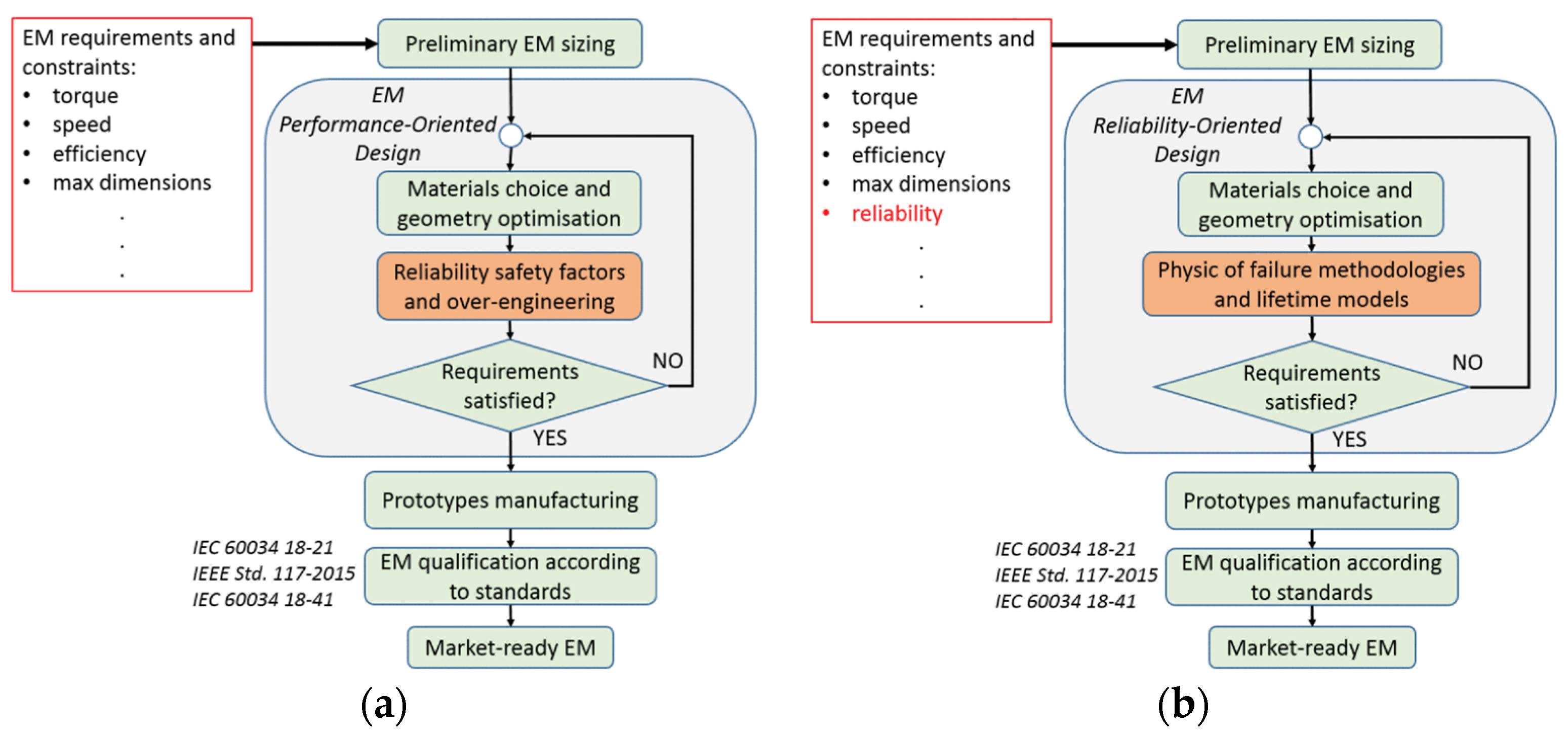
2. Enabling the POF Approach for Inverter-Fed Low-Voltage EMs

The main challenge for adopting the POF approach for EMs is to identify the insulation stress and find a proper lifetime model. This section starts with an introduction to the insulation stresses faced by inverter-fed low-voltage EMs and the concept of dominated stress (i.e., prevailing aging factor) is highlighted in order to select the suitable lifetime model. Finally, a possible and reasonable way of adopting the POF approach for inverter-fed low-voltage EMs is presented.

2.1. Insulation Stresses Acting on Inverter-Fed Low-Voltage EMs

In general, the winding insulation is subjected to the so-called TEAM stresses [27] which are thermal, electrical, ambient, and mechanical stresses. Each stress is introduced in detail in the following subsections.

2.1.1. Thermal Stress

Thermal aging is probably the most recognized reason which causes insulation degradation and leads to premature failure. The deterioration is basically an oxidation process. Indeed, at adequately high temperature, the chemical bonds within the insulation organic material tend to break, and oxygen is likely to attach the broken bonds. Therefore, the polymer chain becomes shorter and weaker which eventually leads to insulation breakdown [28]. Thermal degradation is a long-term process, whose influence on the insulation’s probability of failure might start to be perceivable only after several hours of operation. Accordingly, accelerated aging tests are generally employed to study this phenomenon, and eventually to qualify the insulation. The test sample for an aging test could be either the whole EM or an equivalent small test model. The model containing all of the insulation elements proportionately reduced in size was developed by Cypher and Harrington [29] and is termed as “motorette”. The two common structures of motorette are shown in Figure 2: “Configuration A”, which is proposed in IEEE and IEC standards, is a general option for a wide range of EMs, while “Configuration B” is a more specific solution closely depending on the machine geometry. Both configurations are viable options, since the compulsory insulation system is considered. After the test sample preparation, the accelerated aging test is conducted following the procedure recommended in technical standard from IEEE [30] or IEC [31]. An example of test process for Class A insulation is shown in Figure 3. The thermal stress is considered as dominant/prevailing aging factor over mechanical and environmental stresses, although vibrations and humidity exposures are also performed. At least three test groups with different aging temperatures are needed for lifetime model derivation. A voltage test is used to check if insulation reaches the end-of-life for each cycle. After the voltage test, a series of diagnostic tests such as insulation resistance, loss tangent can be performed. Monitoring and recording the changes of these quantities may help in better understanding the aging process. The investigation on properties change during thermal aging process can be focused on resistance [32,33,34], capacitance [33,35,36,37,38], dissipation factor [34,36,37], and PDIV [34,35], and application of these findings can be found in papers on condition monitoring of insulation degradation [39,40,41,42,43,44]. Moreover, the diagnostic test may be used to determine the end of test life, either complementing the voltage tests or replacing them [31]. As mentioned above, for low-voltage EMs adopting a Type I insulation system, the occurrence of PD generally means the end of sample life. Thus, the inception of PD can also be used as the end-of-life criterion [45]. After the test, life data can be post-processed through a statistical approach and fit into the well-known Dakin’s equation for evaluating the reliability of the insulation system. Details are discussed in the following section. Considerations on how to conduct the thermal-accelerated aging test and relative data post-processing can be found in [46].
In addition, materials of the insulation system have different thermal expansion ratios. When they are exposed to heat, materials will expand at a different rate, leading to thermal-induced mechanical stress on the insulation. If the machine is operated under a heavy thermal cycle, then the thermal-mechanical aging should be considered [47]. A possible solution to avoid thermal-induced mechanical stress would be to remove the impregnation [48] and this method is seen in [49] with the phase separation achieved by concentrated winding topology. The absence of impregnation minimizes the occurrence of thermally induced mechanical stress, as the winding can expand freely, when heated, within their allocated volume. However, non-impregnated winding also suffers from (1) poor thermal performance (because of a lower equivalent thermal conductivity orthogonally to the conductor length); (2) poor mechanical integrity when subject to vibrations or shocks. Unfortunately, this topic is not widely covered in literature, thus further studies are needed. In order to account for the thermal–mechanical stress, a variable temperature profile may be used instead of constant temperature during the accelerated aging test. However, there is a gap in testing the low-voltage machine as technical standards only mention the thermal cycle test [50,51] for form-wound windings. An example of a variable thermal profile aging test for low-voltage EMs could be found in [49]. Moreover, the lifetime prediction considering thermal–mechanical stress can be found in papers [47,52,53] and Ph.D. Thesis [48]. Detailed explanations will be presented later.

2.1.2. Electrical Stress

Mains-fed low-voltage EMs are mainly subjected to thermal stress and vibration [54]. However, with the advent of variable speed drive (VSD), the newly developed electrical stress caused by the repetitive, impulsive voltage challenges the winding insulation. The replacement of the BJT with IGBT and MOSFET has led to an even higher switching frequency, with the potential of several tens of kV/μs rise fronts and a 50 kHz pulse repetition frequency [26]. Moreover, there is a trend toward the use of the WBG technology in the electrical drive aimed at 100 kV/μs rise fronts and operated at a 500 kHz switching frequency [55], offering the advantage in developing an efficient, lightweight, and compact system also with the ability to operate in the high temperature [56]. The development of the switching technology offers the merits of switching loss minimization and more stable torque [26] and also pushes the electrical stress to a high level. As stated in IEC 60034-18-41, the voltage at the machine terminal can be twice as high as the inverter terminal voltage due to the impedance mismatch [22,57]. The overvoltage factor (OF) which is the ratio between machine terminal voltage and inverter terminal voltage is summarized in Figure 4 [22], depending on the cable length and inverter rise time tr. In addition, the work extending the rise time ranging from 50 ns to 10 ns is presented in [58] to predict the effect caused by the WBG device. As a result, the voltage overshoot may reach the level to incept the PD, which is mainly responsible for insulation failure of inverter-fed low-voltage EMs [59]. Thus, the PD-free design is necessary for the low-voltage inverter-fed EMs.
Apart from permanent breakdown caused by PD, several studies have investigated the aging effect of electrical stress. In [60], N. Lahoud performed the multi-stress accelerating aging test based on the design of experiments (DOE) with the result presented in Figure 5, where M is the average lifespan, log(V) and log(T) represent the voltage effect and temperature effect on lifetime, respectively. The findings of this study suggest that under the PD regime, both electrical stress and temperature can lead to the reduction of the lifetime. In another paper, the electrical accelerated aging test is conducted both in the absence (oil) and presence (air) of PD regime as shown in Figure 6 [61]. The evidence from this study suggests that electrical stress affects the lifetime reduction and the influence becomes much more obvious in the presence of PD. Moreover, experimental findings in [62] indicate that high frequencies, short rise times, and fast oscillating pulses shorten the lifetime. However, if no PDs occurred, even after two years under considerably high electrical and thermal stress, no breakdown was observed. Based on these findings, treating the partial discharge inception voltage (PDIV) as the threshold for the electrical aging is reasonable, and thermal or thermal–mechanical stress would be the dominant aging factor if no PD occurs. This assumption is widely adopted in past papers [41,45,63,64,65].

2.1.3. Mechanical Stress

The power frequency currents will lead to a magnetic force oscillating at twice the power frequency. If the coils in the slot are loose, then vibration is induced and the insulation is mechanically stressed [28]. Moreover, the rotor can affect the insulation, e.g., rotor unbalance [3,66]. The mechanical stress can also come from external factors such as the vibration of a whole system which is common in mobile applications. There is no well-accepted model which can describe the aging caused by mechanical stress. Alternatively, the vibration is treated as a secondary effect factor during the main degradation process, e.g., thermal aging. As shown in Figure 3, a vibration exposure for 1 hour is adopted during the thermal aging test [31]. Moreover, the system-level vibration can be considered during the test [45] by adopting a vehicle vibration profile referring to the ISO standard [67].

2.1.4. Ambient Stress

Stresses stemming from contamination, high humidity, aggressive chemicals are categorized as environmental or ambient stress [28]. The single factor will not cause aging but the combination with other stresses may lead to aging. Thus, the ambient stress is commonly treated as “factors of influence” and according to IEC standard [31], the test samples should be exposed to the humidity environment to take into account the ambient stress.
In addition, the ambient conditions (e.g., pressure) can also impact the partial discharge phenomenon. A detailed analysis is introduced in Section 3.

2.2. The Feasible Lifetime Models

There is no doubt that a multi-stress lifetime model is always needed to accurately predict the lifetime. However, due to the complexity of distinguishing and quantifying the aging contribution caused by the simultaneous action of two or more aging factors (i.e., coupled, or combined aging effect), the single stress lifetime model is preferred. In other words, the winding is never damaged by the single aging factor but is often possible to determine which aging factor has the biggest effect [68]. Moreover, there is no generally accepted multi-stress lifetime model which could be used for reliability evaluation. The assumption of predominant aging factor is common in literature [7,69,70] and standard [27] and the feasibility has been proved by subsequent experimental results presented in technical publications [71]. As mentioned previously, a sub-cycle is applied during the accelerated aging test to account for the secondary effect (e.g., humidity and vibration).
If the machine is assumed to be PD-free and there is no heavy thermal cycle, then the thermal degradation is the dominant aging stress. Currently, the most recognized lifetime model describing thermal degradation is the one proposed by Dakin in 1948 [72] based on the Arrhenius equation, where the insulation degradation process is treated as a chemical process and the thermal lifetime depends on the activation energy and reaction rate of the particular degradation reaction. The lifetime L (in unit measure of time) under operating temperature θ calculated by Dakin’s equation is expressed as:
L θ = a · exp b / θ
where a and b are parameters depending on the material properties [73]. Due to the limited wear-out data of electrical machines, these parameters are commonly derived from the accelerated aging test. The adoption of Dakin’s equation can be seen in the thermal qualification standards [30,31] and published papers [45,46,49,74,75,76,77,78,79,80,81,82,83,84,85,86,87,88,89,90,91,92,93]. However, most of the papers simply apply Dakin’s equation by assuming the thermal stress as the dominated aging factor without any preconditions (e.g., PD-free), which would lead to the inaccuracy of prediction. For example, if the PD occurs during the operation, the insulation will be aged very soon due to the electrical stress or even fail permanently. In addition, the lifetime model parameters (i.e., a and b) used in some papers are provided by Brancato in [75]. These data are based on an accelerated aging test on 62 Navy motor insulation systems and 31 industrial-type motor insulation systems following IEEE standards. However, the author believes the lifetime model parameters should be derived based on the costumed motorette corresponding to machine design which would account for different slot fill factor, insulation selection, and other factors related to machine design which could affect the lifetime. In conclusion, Dakin’s equation is a feasible lifetime model for POF, but it should be adopted with cautions.
For transportation applications, a variable load cycle is often the case which leads to a variable temperature profile. However, Dakin’s equation is applicable for a single temperature. Simply using the average value of the variable temperature profile to predict the lifetime may lead the inaccurate prediction [74]. Alternatively, the cycle counting method (e.g., rain flow-counting algorithm) could transfer the thermal cycle into mean temperature [94]. Moreover, instead of using average temperature, the method in [94] which combines the cumulative damage law [95] with Arrhenius law will give a more accurate estimation. For every infinitesimal interval dt, the temperature can be seen as constant and thus the Arrhenius equation can be applied. The fraction loss of life dLF for each time interval is:
d L F = d t L θ i t  
Then the loss of life LFcycle for each cycle Δtcycle can be derived by the simple integration:
L F c y c l e = 0 Δ t c y c l e d L F = 0 Δ t c y c l e d t L θ i t  
By adopting Equation (3), the thermal lifetime under variable load can be estimated more accurately.
Moreover, as mentioned in Section 2, the repetitive temperature change may lead to thermal–mechanical fatigue. If the machine is undergoing a heavy thermal cycle, then the mechanical stress cannot be neglected [47]. A possible method would be taking the mechanical effect through the strain-life model for low cycle fatigue [48] and stress-life (S-N) model for high cycle fatigue [48,53]. The strain-life model is used [96] to describe the relationship between the plastic strain and the total number of cycles till fatigue. While stress-life model describes the relationship between the maximum stress of the cyclic elastic deformation Smax and the required cycles to the failure N, assuming that the cyclic mechanical stress is sinusoidal. A typical tension-fatigue curve of polyamide-imide (PAI) resin is shown in Figure 7. Once the fatigue stress is known, then the lifetime due to the thermal-mechanical stress can be obtained.
Alternatively, a multi-stress thermal-mechanical lifetime is used in [47] as a combination of Dakin’s Equation accounting for thermal aging and an inverse power law accounting for mechanical aging:
L T M = L T L M G
Being LT−M the lifetime under thermal–mechanical stress, LT and LM are the single thermal stress life and mechanical stress life respectively with G being the correlation factor. Moreover, Griffo et al. [52] used the Miner’s rule combined with the counting method to evaluate the induced mechanical effect while the Arrhenius Equation is used for thermal aging. A look-up table is built based on the experiment results for estimating the lifetime caused by thermal cycle stress at different temperature swings and peak temperatures. Moreover, as stated in [97], when there is no available or accurate lifetime model, a new model can be developed using a series of statistically designed experiments. An example of multi-stress lifetime model derivation based on DOE can be found in [60]. Although the author focuses on thermal and electrical stress modeling, it could be a good reference for lifetime development considering thermal–mechanical stress under a heavy thermal cycle.

2.3. The Feasibility of Adopting POF for Inverter-Fed Low-Voltage EMs

POF is a new topic on the EM application and only a few papers can be found on this topic [90,98,99]. The main barriers which impede the application of this method in the past are summarized as follow:
  • The lack of fully understanding the physics of insulation degradation due to the complex operating and environmental conditions and interaction effect of multiple stress;
  • The limited wear-out data of EMs compared with power electronics (PE) components.
However, based on the past study on insulation, a simple way to adopt POF in EM design is possible; refer to Dakin’s Equation, the only input parameter would be the temperature. Thus, it is desirable to transfer the operating conditions into a temperature profile. Typically, thermal performance is evaluated through lumped parameter thermal network (LPTN) [100,101], finite element method (FEM), and computational fluid dynamic (CFD) [102]. According to the papers [45,46,49,74,75,76,77,78,79,80,81,82,83,84,85,86,87,88,89,90,91,92,93] estimating the thermal lifetime using the Arrhenius Equation, it is easily found that the LPTN is the most common approach [49,77,79,80,82,83,93], comparing with limited paper using FEM [89]. One possible reason could be that the LPTN is the most user-friendly solution for a fast and low-computation time-consuming thermal analysis [102]. Moreover, the influence of thermal aging on the thermal properties of EMs is investigated in [103,104] which can be easily integrated into the lifetime prediction process through LPTN.
Then it is possible to evaluate the lifetime under different inputs of the POF model (i.e., environment conditions, operating conditions, and machine design). Papers on investigating unhealthy voltage conditions on the lifetime can be found covering voltage imbalance [77,78,79,80], voltage harmonics [77,78,80], over/under voltage [79], and voltage fluctuation [88]. The unhealthy voltage conditions transfer to temperature through an electrical and thermal model. Then the Dakin’s Equation is applied to evaluate the effect of unhealthy conditions on lifetime. For EMs under transportation application, the operating conditions (e.g., driving cycle/mission profile) matters. Several papers focus on the lifetime prediction with the real driving cycle or mission profile [49,81,84,91,94,105]. The authors in [49] present a comprehensive analysis of the thermal overload effect on machine lifetime. The electromechanical actuator mission profile and LPTN are combined to derive the variable temperature profile, and the lifetime model parameters are derived through an accelerated aging test with a test sample thermally exposed to the previously obtained temperature profile. Then, the lifetime under this thermal overload profile can be estimated. Similar works can be found in [81,84]. By combining the vehicle driving cycle and the lifetime model, the authors reveal that the machine can have a longer lifetime under the actual driving cycle than expected, i.e., 20,000 h lifetime, which means the oversizing of the machine. This problem has early been mentioned in [76]. The concept “lifetime-oriented design” is proposed in the paper, highlighting that the machine can be designed or operated higher than the rated power by evaluating the lifetime consumption. Moreover, different geometries and cooling methods may influence the thermal performance and thus the thermal lifetime, which means the machine design can also be linked with lifetime model via thermal model (e.g., LPTN). The work in [105] comparing the two cooling method under a typical driving cycle and the result reveals a better solution in terms of lifetime.
Based on the discussion above, it is possible to conclude a simplified lifetime prediction process taking the thermal stress as the dominated aging factor as shown in Figure 8 and it is easy to further take thermal–mechanical stress into account by modifying this process. Starting from the primary machine design which meets the performance requirement (e.g., power, torque), the thermal model is built based on the machine geometry, cooling method, and insulation selection. The derived model will take the mission profile as the input to calculate the corresponding temperature profile. The motorette will be built specifically based on machine design and then it will be subjected to the thermal accelerated aging test following the technical standard for lifetime model derivation. The aging temperature and aging time will depend on the thermal class of the selected insulation material. Environmental conditions like humidity and vibration will also be taken into account during the aging test. Finally, the lifetime will be estimated by taking the temperature profile as the input of the lifetime model.
The applicability of POF discussed above is based on the assumption of PD-free operation. Hence, the winding insulation lifetime estimation via Dakin’s Equation will deliver accurate results only in absence of PD, i.e., the EM fulfills the PD-free design requirement. Thus, the next section will mainly focus on the design of PD-free EMs.

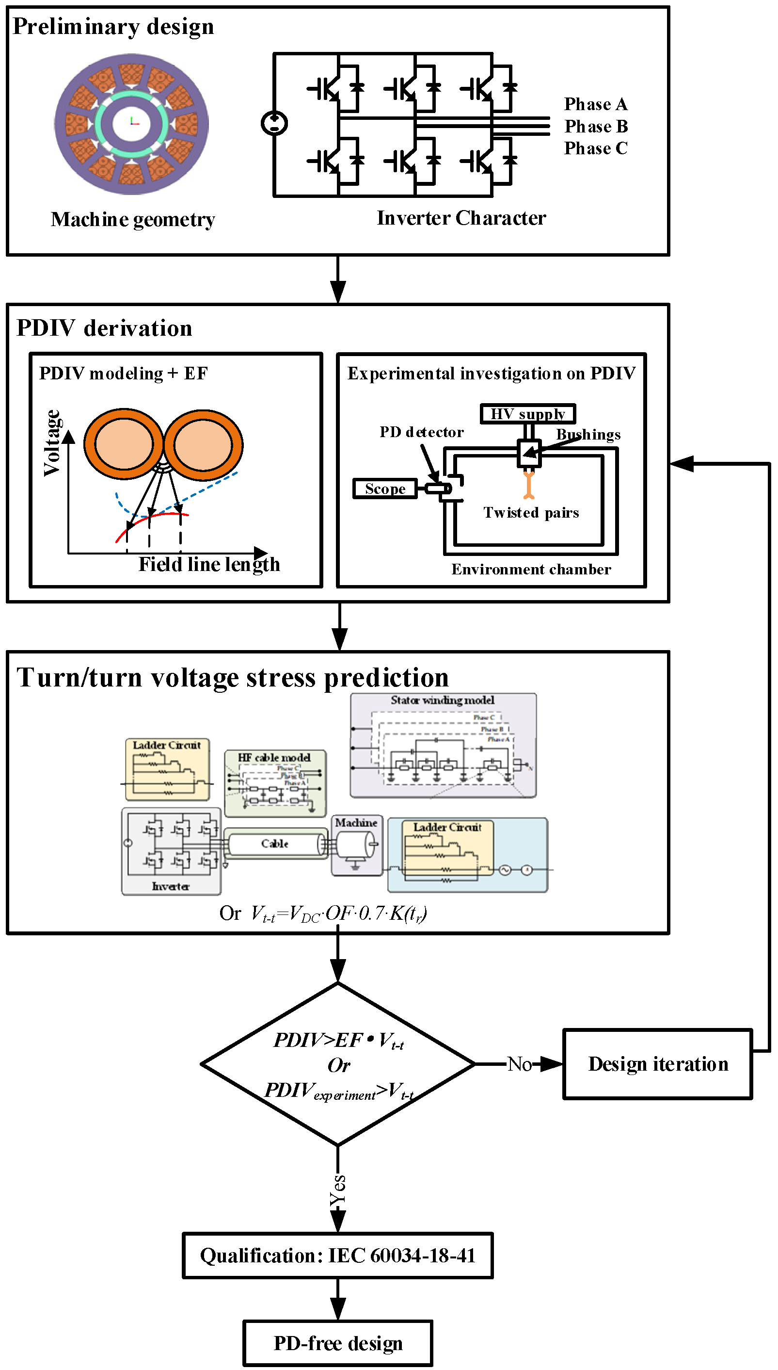
3. On the Design of PD-Free EMs

A PD is an electric discharge that only partially bridges the insulation between electric conductors and is commonly seen as the discharges in gases and the vicinity of solid/gas-insulating interfaces for low-voltage EMs [106]. According to the previous work, the premature failure of inverter-fed low-voltage EMs is due to the PD occurring in the inter-turns insulation [12]. The overshoot voltage at the motor terminal can be twice as high as the inverter terminal voltage due to the mismatch between impedance and this overshoot can reach levels at which PD is triggered in the air gap between adjacent wires. The PDs erode the insulation and consequently lead to an inter-turns breakdown. Until now, there is still not a full understanding between the PD phenomenon and insulation design, especially with the application of WBG technology. Thus, stronger insulation (e.g., oversize the insulation, use double insulation, increase the insulation grade, etc.,) is commonly applied to guarantee PD-free operation. However, this strategy will compromise the EM performance (i.e., power density, fill factor), which goes against the aim of ROD. Hence, this section aims at investigating on PD phenomenon and how to adopt the findings to design PD-free machines, paying close attention to the turn/turn insulation since it is the weakest subsystem and the occurrence of PD in turn/turn is the cause of premature failure of stator windings. The section starts with the voltage transient modeling and partial discharge modeling. These analytical methods enable machine designers to primarily evaluate the PD risk during the design stage. According to the IEC standard [22], an empirical factor which is called the enhancement factor (EF) is commonly adopted to account for the effect of influence factors on partial discharge inception voltage (PDIV) for safe operation. To move toward the ROD, the EF should be replaced with a more accurate value by understanding the physics of partial discharge through experimental exploration. Thus, the past work focusing on the experimental investigation of the PDIV is reviewed. Finally, as a summary of the work mentioned above, the strategy of designing PD-free EMs is highlighted.

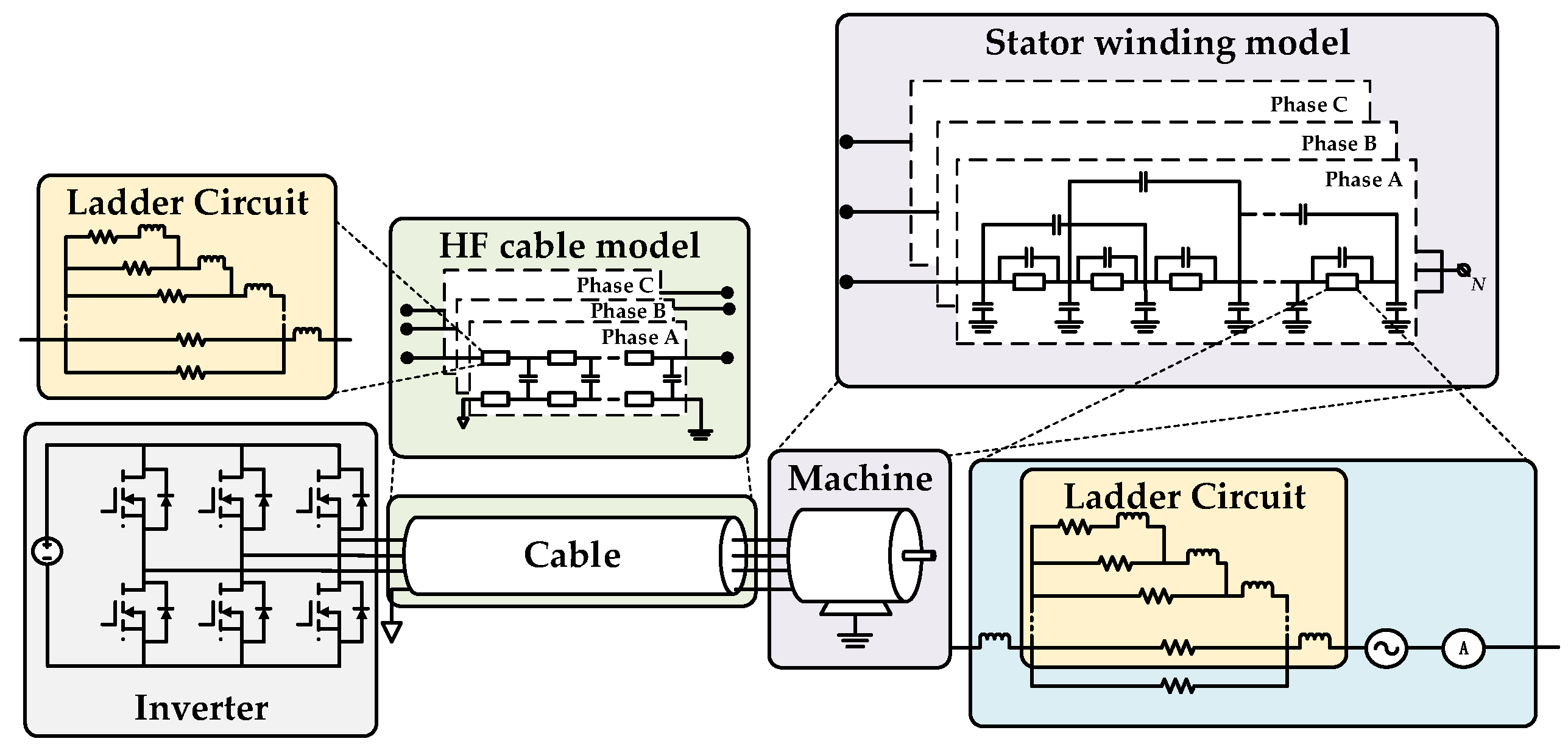
3.1. Modelling of Voltage Transient

As stated in the IEC standard [22], the inter-turns voltage Vt−t can be derived by:
V t t = V D C · O F · 0.7 · K ( t r )
VDC being the DC link voltage, K(tr) is a function of the rise time and approaches one only for a very short rise time (<50 ns); OF has been mentioned before as shown in Figure 4, and a winding factor of 0.7 is adopted accounting for voltage distribution [58] and may be useful when the experiment and simulation are missing. In addition to the adoption of empirical factors, the high frequency (HF) model considering machine parameters can be used to predict both the EM terminal voltage [107,108,109,110,111,112,113,114,115] and turn/turn voltage [107,108,114,116,117,118,119]. An example could be found in [108] as shown in Figure 9. A system-level model combining inverter, cable, and the machine is used to simulate the voltage at the machine terminal and a stator winding model is accounted for the turn/turn voltage distribution. These models can potentially build the relationship between the machine parameters and PD risk which is helpful to establish the PD-free design strategy.

3.2. Modelling of Partial Discharge

The breakdown voltage can be modeled by either Paschen’s law [59,65,120,121,122,123,124,125,126,127,128,129,130] or streamer inception criterion [54,131,132,133,134]. Paschen’s law is an equation that gives the breakdown voltage, that is, the voltage necessary to start a discharge or electric arc, between two electrodes in a gas as a function of pressure and gap length [135]:
E = U d = B · P ln A · P · d ln 1 + 1 / γ  
E being the applied electric field, U the breakdown voltage, P the pressure, d the gap distance, and γ the Townsend’s secondary emission coefficient, A and B are the coefficients that depend on the considered gas and temperature. A schematic illustrating the derivation of PDIV using Paschen’s law is shown in Figure 10. The voltage level, which Paschen’s curve and the voltage drop across field lines contact at a single point, is the estimated value of PDIV.
However, the author in [54] argues that Paschen’s law can be only applied to the uniform fields under quasi-static conditions and another partial discharge modeling approach called streamer inception criterion should be applied [54]. The streamer inception law starts from the well-known critical avalanche criterion [136]:
0 x c r α ¯ E x d x K c r
E(x) being the field distribution along the streamer path and Kcr the logarithm of a critical number of electrons, ā the effective ionization coefficient, x the spatial coordinate along the streamer path, and xcr is the distance at which E is equal to the critical value Ecr. By applying the Equation (7) to spherical voids in insulating materials, the breakdown field can be derived as [133]:
E i n c = E 1 / p c r p 1 + B / ( p d ) n / f
where (E1/p)cr, B, and n are the ionization parameters for the gas, p is the pressure in the void, d is the void diameter, and f is the dimensionless field enhancement factor. The adoption of Equation (8) in estimating PDIV in EMs can be found in [131,132,134]. Another approach of PDIV estimation using streamer inception criterion can be found in [54]. A series of simulations are conducted using FEM to obtain the desired Kcr and then the breakdown filed.
In addition to the analytical approach, the PD-free criterion in [134,137] is derived by summarizing the experiment result under several test conditions into an empirical Equation and this Equation is used to check the design in other conditions.

3.3. Experiment-Based Studies on PD

According to the IEC standard [22], for a safety design (i.e., PD-free design), the inter-turns PDIV should be higher than the expected turn-to-turn voltage derived by Equation (5) multiplied by an enhancement factor (EF):
P D I V t t > V t t · E F
The EF accounts for the temperature and the aging effect on PDIV, and the fact that PD extinction occurs at a voltage lower than PDIV (the PD extinction voltage (PDEV)). Moreover, there are some factors (e.g., humidity, pressure, inverter characteristics) that can also impact the PDIV but are not accounted for in the EF. To pursue high-performance EMs, understanding the physics of partial discharge is necessary instead of adopting the empirical enhancement factor. Many works dedicate to investigate the influence factors on PDIV or RPDIV of turn/turn insulation [54,62,120,123,138,139,140,141,142,143,144,145,146,147,148,149,150,151,152,153] through experiments. A typical experiment setup for PDIV investigation is presented in Figure 11. Twisted pairs are the preferred test sample since turn/turn is the weakest subsystem subjected to the partial discharge [62,154] and twisted pairs are the easiest sample to evaluate the inter-turn PD phenomenon according to the IEC standard [22]. An environment chamber is used to study the influence of ambient conditions (i.e., temperature, pressure, and humidity). In terms of source, a high-voltage pulse generator is adopted instead of a sinusoidal source to follow the real operational conditions of inverter-fed EMs. For PD detection, an optical approach using photomultiplier has an advantage over others in terms of noise immunity, especially under the very high switching frequency of voltage.

3.3.1. Effect of Ambient Conditions

Both temperature [54,62,120,123,140,141,142,155] and pressure [120,138,142,143,144,152,153] have great impact on the PDIV. In general, the PDIV decreases with the increase of temperature and the reduction of pressure. When the pressure goes below a certain threshold, PDIV increases with the further decrease of pressure as shown in Figure 12 [138].
This phenomenon is expected. Referring to Paschen’s law, for a fixed distance between two turns, there would be a certain pressure threshold that represents the lowest PDIV and the pressure level below or above this point will have a higher PDIV. According to the PD modeling approach mentioned above, either Paschen’s law or streamer inception criterion takes the pressure effect into account. To further account for the thermal effect, Paschen’s law is modified in [123,126,142,144] to take the temperature as a parameter of the model. Moreover, the equivalent pressure is used combined with streamer inception criterion to take both temperature and pressure effect into account in [54]. Besides the analytical model, the curve-fit approach is adopted in [120] to describe the relationship between PDIV and temperature based on the experimental findings. The same method can be found in [134,152] where both temperature and pressure are considered. Humidity can also influence the PDIV, and the investigation on twisted pairs can be found both under ac voltage [121,140,145,156] and surge voltage [140]. No general tendency can be concluded since the effect of humidity may both depend on temperature [156] and voltage type [140]. An attempt trying to explain the humidity effect on PDIV is given in [121] based on the relationship between space charge and PDIV presented in [157].

3.3.2. Effect of Thermal Aging

The thermal aging effects on PDIV has been studied in [35,139,142,152] and all the experimental results indicate the decrease of PDIV with time of aging. The authors of [152] argue that for MEA application, thermal aging is not as severe as industry application, and the aging enhancement factor is modified as:
E F A g i n g = max 1 , 1.1 × T S / T C
Ts and Tc being the service and class temperature, respectively. A similar consideration is proposed in [120], where the authors suggest that the thermal aging effect can be neglected for MEA applications.
The work attempting to model the thermal aging effect on PDIV can be seen in [142], claiming that the main change of PDIV is due to the relative permittivity change of the insulation coating. By taking the relative permittivity change with thermal degradation into the PDIV modeling, the analysis result shows a good match with the experimental results.

3.3.3. Investigation on PDEV

The investigation on PDEV can be found in [120,155,158,159,160]. The higher voltage level and longer rise time lead to a high PDEV [158,159,160] and higher switching frequency and temperature may lead to lower PDEV [155]. A safety factor of 1.25 is recommended in the IEC standard [22] and the experimental findings reported in [120] tend to agree on this value, for round enameled wire specimen. However, the authors compared the measured PDEV and PDEV calculated by safety factor at different temperatures as shown in Figure 13, indicating the single factor of 1.25 for all operating points is unsuitable [155].
Moreover, according to the experiment result as shown in Figure 14 [155], PDEV decreases with the increase of frequency, while the PDIV almost does not change. These findings highlight the requirement of a deep understanding of PDEV to better and safely design the PD-free machine.

3.3.4. Effect of Insulation Thickness and Conductor Diameter

Refer to Equation (6), the breakdown electrical field depends on the distance which means conductor diameters and insulation thickness will impact PDIV although these effects are not mentioned in the standard. Published papers can be found focusing on insulation grade [54,62,123,152] and conductor diameter [54,62,123] effect on PDIV. An empirical model considering grade, diameter, and pressure is proposed to model the PDIV [137] and a tool is developed in [129] aiming at designing a PD-free EM considering grade and diameter. Moreover, the outcome in [54] turns out to be a recommendation chart of PDIV at the worst case as shown in Figure 15, for different conductor diameters and insulation thickness. This could be a useful reference for EM designers during the wire and insulation selection.

3.3.5. Effect of Surge Voltage Characteristic

The impulsive voltage caused by the inverter may influence PDIV although the effect is also not highlighted in the standards. Typically, a surge voltage is characterized by rise time, repetition frequency, and duty cycle and a couple of work studying the influence on PDIV can be found for each topic: rise time [62,130,138,148], frequency [138,143,144,145,147,148,149,153], and duty cycle [147,148]. To account for the potential insulation challenge caused by the WBG device, some papers have conducted the investigation based on the WBG device. The rise time can be down to 7 ns [138] with a slew rate of 140 kV/μs and the switching frequency can reach 600 kHz [159]. Unfortunately, there is no general conclusion that can be drawn based on these papers since the test voltage conditions are quite different and the PDIV may be affected by the combination of rise time, frequency, and duty cycle. In general, rise time will have a quite large impact on PDIV while the frequency and duty cycle have less influence. A volume–time theory-based simulation model is attempted to account for the rise time effect in [130], and a good match can be found at the rise time of 80 ns. Moreover, a try on PDIV modeling combining pressure and frequency can be found in [144] although the result does not show a good match.
As stated in IEC 60034-18-41 [22], the insulation system can be both qualified using sinusoidal voltage or impulsive voltage. However, the study in [138,140,150,151,157,161,162] indicates that there could be a difference between PDIV measured by sinusoidal voltage and surge voltage, and the level of the inverter can have a strong influence [150,151]. Moreover, the polarity of the square wave may also impact PDIV [59,157,162]. Thus, the EM is recommended to be tested under surge voltage [163] with test conditions similar to the real operating conditions.

3.4. Design of PD-Free EMs

The work mentioned above helps to understand the physics of partial discharge and the PD-free design methodology can be found in published papers [54,65,120,128,134,137,152] and Ph.D. thesis [106]. Based on the findings above, it is possible to conclude a general PD-free design methodology as shown in Figure 16.
Starting from machine design and inverter characteristics, PDIV is first estimated either using an analytical model approach combined with enhancement factor or experimental derivation. Note that the experimental investigation mainly focuses on the effect of different conditions (e.g., pressure, temperature, switching frequency, etc.,) on PDIV which is empirically assumed in EF. Then the turn/turn voltage stress can be modeled either by high-frequency circuit model or empirical factor as shown in Equation (5). Then the PD risk can be evaluated by Equation (9) or the below Equation:
P D I V e x p e r i m e n t > V t t
where PDIVexperimental represents the PDIV derived by experiment taking the influence factors (e.g., ambient, aging) on PDIV into account; thus, there is no need to correlate PDIVexperimental by EF. The design iteration is needed to obtain the best performance while avoiding the PD risk. It is important to note that the process in Figure 16 is the PD-risk evaluation at the design stage while the final market-ready product should be developed before qualifying according to the IEC standard.

4. Moving towards a Reliability-Oriented Design Approach of EMs

There are two possible solutions to move toward a ROD approach of EMs. First, Researchers should keep the continuous investigation on the insulation degradation from physical and chemical aspects for developing a more accurate lifetime model. Alternatively, a simple but recognized lifetime model will be used by carefully adopting a series of assumptions and pre-condition to predict as reliable as the real result. This paper mainly focuses on enabling the second approach through reviewing the past papers and tries to fill the gap between insulation degradation and machine design. Fortunately, for inverter-fed low-voltage EMs which are free of PD, treating thermal or thermal-mechanical stress as the dominated aging factor is acceptable. Combining the work in Section 3 and Section 4, it is possible to give a more comprehensive ROD process. The EM should be first designed to be PD-free considering the converter’s parameters (e.g., switching frequency, DC link voltage), then the lifetime can be estimated through the Dakin’s Equation or thermal-mechanical model. Many rounds of design iterations are needed to meet the reliability requirement while pursuing better performance at the same time. An expected achievement through the ROD can be seen in Figure 17. Through understanding the physics of failure, the over-engineering issue can be avoided to some extent which means lower grade insulation (i.e., thinner insulation) or higher current density may be adopted to obtain a higher power density while keeping the reliability requirement at the same time. It is worth mentioning that the ROD is a design methodology during the design stage. However, the final prototype should be qualified by technical standards before becoming a market-ready product. Thus, there is no need to doubt whether the real life of the EM is equal to estimation by the so-called lifetime model or not, which is both hard and impossible. However, continuous investigation on the dielectric area allows EM designers to assess the reliability during the design stage instead of empirical design and over-engineer factors adoption. The main effort should be put into making the lifetime prediction as reliable as possible.

5. Conclusions

High-performance and reliable EMs are more and more demanded by transportation electrification applications. Hence, the PoF methodology, which considers both operational and environmental conditions as input and based on the lifetime model predicts the EM reliability level, should be employed since the early EM design stage (i.e., reliability-oriented design) in order to avoid the EM over-engineering. By applying the PoF approach to the EM design, satisfactory reliability figures can be reached without compromising the EM performance. The paper provides an overview regarding the major investigations in the area of dielectric materials typically adopted for EMs manufacturing and their implication on EM design. The main aim of this work is to pave the way for enabling the reliability-oriented design for inverter-fed low-voltage EMs, which are the most suitable candidates for transportation of electrification applications.
The review begins with a general background on the stresses (i.e., TEAM stresses) faced by inverter-fed low-voltage EMs and then focuses on PD-free design and lifetime prediction. Finally, a comprehensive reliability-oriented design process is presented as a potential solution to achieve a reliable and high-performance EM. Indeed, assuming an EM designed to be PD-free, the thermal stress becomes the dominant aging factor and Dakin’s Equation can be used to accurately predict the lifetime. From a practical point of view, accelerated aging tests are commonly performed to derive the lifetime model. In particular, an adequate number of test samples (i.e., specimens), which are built based on the specific EM design and materials, are thermally aged at three different temperatures according to IEC or IEEE standards. The experiment-based lifetime model (i.e., outcome of the POF methodology) will be then used at the EM design process to preliminary assess the EM reliability in order to meet the demanded reliability figures. By adopting such a strategy, it is expected to improve the dielectric material exploitation through an appropriate design of insulation, while ensuring the key EM performance indicators (e.g., power density).
The EM reliability-oriented design discussed in this paper represents a feasible and convenient approach to be employed by EM designers in order to find out the best trade-off between reliability and performance according to the application under study.

Author Contributions

Investigation, Y.J.; writing—original draft preparation, Y.J.; writing—review and editing, P.G. and V.M.; supervision, W.Z. and M.G. All authors have read and agreed to the published version of the manuscript.

Funding

This research was funded by the National Key R&D Program of China, grant number 2017YFB0102304.

Data Availability Statement

The article information collected in this review is data available in publicly accessible repositories: IEEE Xplore (https://ieeexplore.ieee.org/Xplore/home.jsp); Scopus (https://www.scopus.com); and were accessed on 2 June 2021.

Conflicts of Interest

The authors declare no conflict of interest.

References

  1. Bilgin, B.; Magne, P.; Malysz, P.; Yang, Y.; Pantelic, V.; Preindl, M.; Korobkine, A.; Jiang, W.; Lawford, M.; Emadi, A. Making the Case for Electrified Transportation. IEEE Trans. Transp. Electrif. 2015, 1, 4–17. [Google Scholar] [CrossRef]
  2. Lukic, M.; Giangrande, P.; Hebala, A.; Nuzzo, S.; Galea, M. Review, challenges, and future developments of electric taxiing systems. IEEE Trans. Transp. Electrif. 2019, 5, 1441–1457. [Google Scholar] [CrossRef]
  3. Madonna, V. Physics of Failure as a Technology Enabler for Electrical Machines in Transportation: Reliability-Oriented Design of Low Voltage Insulation Systems; University of Nottingham: Nottingham, UK, 2020. [Google Scholar]
  4. Giangrande, P.; Madonna, V.; Nuzzo, S.; Galea, M. Design of fault-tolerant dual three-phase winding PMSM for helicopter landing gear EMA. In Proceedings of the 2018 IEEE International Conference on Electrical Systems for Aircraft, Railway, Ship Propulsion and Road Vehicles & International Transportation Electrification Conference (ESARS-ITEC), Nottingham, UK, 7–9 November 2018; IEEE: Piscataway Township, NJ, USA, 2018; pp. 1–6. [Google Scholar]
  5. Lukic, M.; Hebala, A.; Giangrande, P.; Klumpner, C.; Nuzzo, S.; Chen, G.; Gerada, C.; Eastwick, C.; Galea, M. State of the art of electric taxiing systems. In Proceedings of the 2018 IEEE International Conference on Electrical Systems for Aircraft, Railway, Ship Propulsion and Road Vehicles & International Transportation Electrification Conference (ESARS-ITEC), Nottingham, UK, 7–9 November 2018; IEEE: Piscataway Township, NJ, USA, 2018; pp. 1–6. [Google Scholar]
  6. Galea, M.; Giangrande, P.; Madonna, V.; Buticchi, G. Reliability-Oriented Design of Electrical Machines: The Design Process for Machines′ Insulation Systems MUST Evolve. IEEE Ind. Electron. Mag. 2020, 14, 20–28. [Google Scholar] [CrossRef]
  7. Giangrande, P.; Madonna, V.; Nuzzo, S.; Galea, M. Moving Toward a Reliability-Oriented Design Approach of Low-Voltage Electrical Machines by Including Insulation Thermal Aging Considerations. IEEE Trans. Transp. Electrif. 2020, 6, 16–27. [Google Scholar] [CrossRef]
  8. Madonna, V.; Walker, A.; Giangrande, P.; Serra, G.; Gerada, C.; Galea, M. Improved thermal management and analysis for stator end-windings of electrical machines. IEEE Trans. Ind. Electron. 2018, 66, 5057–5069. [Google Scholar] [CrossRef]
  9. Arumugam, P.; Xu, Z.; La Rocca, A.; Vakil, G.; Dickinson, M.; Amankwah, E.; Hamiti, T.; Bozhko, S.; Gerada, C.; Pickering, S.J. High-speed solid rotor permanent magnet machines: Concept and design. IEEE Trans. Transp. Electrif. 2016, 2, 391–400. [Google Scholar] [CrossRef] [Green Version]
  10. Moore, B.J.; Rehder, R.H.; Draper, R.E. Utilizing reduced build concepts in the development of insulation systems for large motors. In Proceedings of the Electrical Insulation Conference and Electrical Manufacturing and Coil Winding Conference (Cat. No.99CH37035), Cincinnati, OH, USA, 28 October 1999; pp. 347–352. [Google Scholar]
  11. Ghassemi, M. High power density technologies for large generators and motors for marine applications with focus on electrical insulation challenges. High. Volt. 2020, 5, 7–14. [Google Scholar] [CrossRef]
  12. Giangrande, P.; Galassini, A.; Papadopoulos, S.; Al-Timimy, A.; Calzo, G.L.; Degano, M.; Galea, M.; Gerada, C. Considerations on the development of an electric drive for a secondary flight control electromechanical actuator. IEEE Trans. Ind. Appl. 2019, 55, 3544–3554. [Google Scholar] [CrossRef]
  13. Wang, H.; Liserre, M.; Blaabjerg, F.; de Place Rimmen, P.; Jacobsen, J.B.; Kvisgaard, T.; Landkildehus, J. Transitioning to Physics-of-Failure as a Reliability Driver in Power Electronics. IEEE J. Emerg. Sel. Top. Power Electron. 2014, 2, 97–114. [Google Scholar] [CrossRef]
  14. Madonna, V.; Migliazza, G.; Giangrande, P.; Lorenzani, E.; Buticchi, G.; Galea, M. The rebirth of the current source inverter: Advantages for aerospace motor design. IEEE Ind. Electron. Mag. 2019, 13, 65–76. [Google Scholar] [CrossRef]
  15. Höpner, V.N.; Wilhelm, V.E. Insulation Life Span of Low-Voltage Electric Motors—A Survey. Energies 2021, 14, 1738. [Google Scholar] [CrossRef]
  16. Sang Bin, L.; Tae-June, K.; Heedong, K.; Taesik, K.; Chaewoong, L. Case studies of stator winding turn insulation failures in medium voltage motors. In Proceedings of the 2017 Annual Pulp, Paper And Forest Industries Technical Conference (PPFIC), Tacoma, WA, USA, 18–23 June 2017; pp. 1–8. [Google Scholar]
  17. Merizalde, Y.; Hernández-Callejo, L.; Duque-Perez, O. State of the art and trends in the monitoring, detection and diagnosis of failures in electric induction motors. Energies 2017, 10, 1056. [Google Scholar] [CrossRef] [Green Version]
  18. Bazurto, A.J.; Quispe, E.C.; Mendoza, R.C. Causes and Failures classification of industrial electric motor. In Proceedings of the 2016 IEEE Andescon, Arequipa, Peru, 19–21 October 2016; pp. 1–4. [Google Scholar]
  19. Avallone, E.A.; Baumeister, T., III.; Sadegh, A. Marks’ Standard Handbook for Mechanical Engineers; McGraw-Hill Education: New York, NY, USA, 2007. [Google Scholar]
  20. Werninck, E.H. Electric Motor Handbook; McGraw-Hill: New York, NY, USA, 1978. [Google Scholar]
  21. Toliyat, H.A.; Kliman, G.B. Handbook of Electric Motors; CRC Press: Boca Raton, FL, USA, 2004. [Google Scholar]
  22. International Electrotechnical Commission. Rotating Electrical Machines-Part 18–41: Partial Discharge Free Electrical Insulation Systems (Type I) Used in Rotating Electrical Machines Fed from Voltage Converters—Qualification and Quality Control Tests; IEC Standard: Geneva, Switzerland, 2014. [Google Scholar]
  23. International Electrotechnical Commission. Electrical Machines-Part 18–42: Partial Discharge Resistant Electrical Insulation Systems (Type II) Used in Rotating Electrical Machines Fed from Voltage Converters-Qualification Tests; IEC: Geneva, Switzerland, 2017. [Google Scholar]
  24. Sciascera, C.; Giangrande, P.; Brunson, C.; Galea, M.; Gerada, C. Optimal design of an electro-mechanical actuator for aerospace application. In Proceedings of the IECON 2015—41st Annual Conference of the IEEE Industrial Electronics Society, Yokohama, Japan, 9–12 November 2015; IEEE: Piscataway Township, NJ, USA, 2015; pp. 001903–001908. [Google Scholar]
  25. Giangrande, P.; Madonna, V.; Sala, G.; Kladas, A.; Gerada, C.; Galea, M. Design and testing of PMSM for aerospace EMA applications. In Proceedings of the IECON 2018—44th Annual Conference of the IEEE Industrial Electronics Society, Washington, DC, USA, 21–23 October 2018; IEEE: Piscataway Township, NJ, USA, 2018; pp. 2038–2043. [Google Scholar]
  26. Cavallini, A.; Fabiani, D.; Montanari, G.C. Power electronics and electrical insulation systems ߝ Part 1: Phenomenology overview. IEEE Electr. Insul. Mag. 2010, 26, 7–15. [Google Scholar] [CrossRef]
  27. International Electrotechnical Commission. Evaluation and Qualification of Electrical Insulation Systems; IEC: Geneva, Switzerland, 2011. [Google Scholar]
  28. Stone, G.C.; Boulter, E.A.; Culbert, I.; Dhirani, H. Electrical Insulation for Rotating Machines: Design, Evaluation, Aging, Testing, and Repair; John Wiley & Sons: Hoboken, NJ, USA, 2004; Volume 21. [Google Scholar]
  29. Cypher, G.A.; Harrington, R. Functional Evaluation of Motor Insulation Systems [includes discussion]. Trans. Am. Inst. Electr. Engineers. Part. III Power Appar. Syst. 1952, 71, 251–253. [Google Scholar] [CrossRef]
  30. IEEE Standards Association. IEEE Standard Test Procedure for Thermal Evaluation of Systems of Insulating Materials for Random-Wound AC Electric Machinery; IEEE Std 117–2015 (Revision of IEEE Std 117-1974); IEEE Standards Association: Piscataway Township, NJ, USA, 2016; pp. 1–34. [Google Scholar]
  31. International Electrotechnical Commission. Rotating Electrical Machines-Part 18–21: Functional Evaluation of Insulation Systems—Test Procedures for Wire-Wound Windings—Thermal Evaluation and Classification; International Electrotechnical Commission: Geneva, Switzerland, 2012. [Google Scholar]
  32. Gyftakis, K.N.; Panagiotou, P.A.; Lophitis, N.; Howey, D.A.; McCulloch, M.D. Breakdown resistance analysis of traction motor winding insulation under thermal ageing. In Proceedings of the 2017 IEEE Energy Conversion Congress and Exposition (ECCE), Cincinnati, OH, USA, 1–5 October 2017; pp. 5819–5825. [Google Scholar]
  33. Gyftakis, K.N.; Sumislawska, M.; Kavanagh, D.F.; Howey, D.A.; McCulloch, M. Dielectric characteristics of electric vehicle traction motor winding insulation under thermal ageing. In Proceedings of the 2015 IEEE 15th International Conference on Environment and Electrical Engineering (EEEIC), Rome, Italy, 10–13 June 2015; pp. 313–318. [Google Scholar]
  34. Liu, X.; Zhang, T.; Bai, Y.; Ding, X.; Wang, Y. Effects of accelerated repetitive impulse voltage aging on performance of model stator insulation of wind turbine generator. IEEE Trans. Dielectr. Electr. Insul. 2014, 21, 1506–1515. [Google Scholar] [CrossRef]
  35. Savin, S.; Ait-Amar, S.; Roger, D. Turn-to-turn capacitance variations correlated to PDIV for AC motors monitoring. IEEE Trans. Dielectr. Electr. Insul. 2013, 20, 34–41. [Google Scholar] [CrossRef]
  36. Madonna, V.; Giangrande, P.; Galea, M. Evaluation of strand-to-strand capacitance and dissipation factor in thermally aged enamelled coils for low-voltage electrical machines. IET Sci. Meas. Technol. 2019, 13, 1170–1177. [Google Scholar] [CrossRef]
  37. Farahani, M.; Gockenbach, E.; Borsi, H.; Schäfer, K.; Kaufhold, M. Behavior of machine insulation systems subjected to accelerated thermal aging test. IEEE Trans. Dielectr. Electr. Insul. 2010, 17, 1364–1372. [Google Scholar] [CrossRef]
  38. Panagiotou, P.A.; Gyftakis, K.N.; Lophitis, N.; McCulloch, M.D.; Howey, D.A. Investigation of traction motor windings′ insulation capacitance at switching frequencies under accelerated thermal stress. In Proceedings of the 2017 IEEE 11th International Symposium on Diagnostics for Electrical Machines, Power Electronics and Drives (SDEMPED), Tinos, Greece, 29 August–1 September 2017; pp. 537–543. [Google Scholar]
  39. Tsyokhla, I.; Griffo, A.; Wang, J. Online condition monitoring for diagnosis and prognosis of insulation degradation of inverter-fed machines. IEEE Trans. Ind. Electron. 2018, 66, 8126–8135. [Google Scholar] [CrossRef] [Green Version]
  40. Zoeller, C.; Vogelsberger, M.A.; Fasching, R.; Grubelnik, W.; Wolbank, T.M. Evaluation and Current-Response-Based Identification of Insulation Degradation for High Utilized Electrical Machines in Railway Application. IEEE Trans. Ind. Appl. 2017, 53, 2679–2689. [Google Scholar] [CrossRef]
  41. Babel, A.S.; Strangas, E.G. Condition-based monitoring and prognostic health management of electric machine stator winding insulation. In Proceedings of the 2014 International Conference on Electrical Machines (ICEM), Berlin, Germany, 2–5 September 2014; IEEE: Piscataway Township, NJ, USA, 2014; pp. 1855–1861. [Google Scholar]
  42. Savin, S.; Ait-Amar, S.; Roger, D. Cable aging influence on motor diagnostic system. IEEE Trans. Dielectr. Electr. Insul. 2013, 20, 1340–1346. [Google Scholar] [CrossRef]
  43. Younsi, K.; Neti, P.; Shah, M.; Zhou, J.Y.; Krahn, J.; Weeber, K.; Whitefield, C.D. On-line capacitance and dissipation factor monitoring of AC stator insulation. IEEE Trans. Dielectr. Electr. Insul. 2010, 17, 1441–1452. [Google Scholar] [CrossRef]
  44. Zoeller, C.; Vogelsberger, M.A.; Wolbank, T.M. Assessment of insulation condition parameters of low-voltage random-wound electrical machine. In Proceedings of the IECON 2016—42nd Annual Conference of the IEEE Industrial Electronics Society, Florence, Italy, 23–26 October 2016; IEEE: Piscataway Township, NJ, USA, 2016; pp. 1470–1475. [Google Scholar]
  45. Mancinelli, P.; Stagnitta, S.; Cavallini, A. Qualification of Hairpin Motors Insulation for Automotive Applications. IEEE Trans. Ind. Appl. 2017, 53, 3110–3118. [Google Scholar] [CrossRef]
  46. Han, C. Lifetime evaluation of class E electrical insulation for small induction motors. IEEE Electr. Insul. Mag. 2011, 27, 14–19. [Google Scholar] [CrossRef]
  47. Sciascera, C.; Galea, M.; Giangrande, P.; Gerada, C. Lifetime consumption and degradation analysis of the winding insulation of electrical machines. In Proceedings of the 8th IET International Conference on Power Electronics, Machines and Drives (PEMD 2016), Glasgow, UK, 19–21 April 2016. [Google Scholar]
  48. Huang, Z. Modeling and Testing of Insulation Degradation due to Dynamic Thermal Loading of Electrical Machines. Ph.D. Thesis, Lund University, Lund, Sweden, 2017. [Google Scholar]
  49. Madonna, V.; Giangrande, P.; Lusuardi, L.; Cavallini, A.; Gerada, C.; Galea, M. Thermal Overload and Insulation Aging of Short Duty Cycle, Aerospace Motors. IEEE Trans. Ind. Electron. 2020, 67, 2618–2629. [Google Scholar] [CrossRef]
  50. International Electrotechnical Commission. Rotating Electrical Machines—Part 18–34: Functional Evaluation of Insulation Systems—Test Procedures for Form-Wound Windings—Evaluation of Thermomechanical Endurance of Insulation Systems; International Electrotechnical Commission: Geneva, Switzerland, 2012. [Google Scholar]
  51. Institute of Electrical and Electronics Engineers. IEEE Recommended Practice for Thermal Cycle Testing of Form-Wound Stator Bars and Coils for Large Rotating Machines; IEEE Std 1310-2012 (Revision of IEEE Std 1310-1996); IEEE: Piscataway Township, NJ, USA, 2012; pp. 1–30. [Google Scholar]
  52. Griffo, A.; Tsyokhla, I.; Wang, J. Lifetime of Machines Undergoing Thermal Cycling Stress. In Proceedings of the 2019 IEEE Energy Conversion Congress and Exposition (ECCE), Baltimore, MD, USA, 29 September–3 October 2019; IEEE: Piscataway Township, NJ, USA, 2019; pp. 3831–3836. [Google Scholar]
  53. Yang, L.; Pauli, F.; Hameyer, K. Influence of thermal-mechanical stress on the insulation system of a low voltage electrical machine. Arch. Electr. Eng. 2021, 70, 233–244. [Google Scholar]
  54. Lusuardi, L.; Cavallini, A.; de la Calle, M.G.; Martínez-Tarifa, J.M.; Robles, G. Insulation design of low voltage electrical motors fed by PWM inverters. IEEE Electr. Insul. Mag. 2019, 35, 7–15. [Google Scholar] [CrossRef]
  55. Ghassemi, M. Accelerated insulation aging due to fast, repetitive voltages: A review identifying challenges and future research needs. IEEE Trans. Dielectr. Electr. Insul. 2019, 26, 1558–1568. [Google Scholar] [CrossRef]
  56. Morya, A.K.; Gardner, M.C.; Anvari, B.; Liu, L.; Yepes, A.G.; Doval-Gandoy, J.; Toliyat, H.A. Wide Bandgap Devices in AC Electric Drives: Opportunities and Challenges. IEEE Trans. Transp. Electrif. 2019, 5, 3–20. [Google Scholar] [CrossRef]
  57. Cavallini, A.; Montanari, G.C.; Fornasari, L. The Evolution of IEC 60034-18-41 from Technical Specification to Standard: Perspectives for Manufacturers and End Users. In Proceedings of the 2012 IEEE International Power Modulator and High Voltage Conference (IPMHVC), San Diego, CA, USA, 3–7 June 2012; pp. 160–164. [Google Scholar]
  58. Madonna, V.; Giangrande, P.; Zhao, W.; Zhang, H.; Gerada, C.; Galea, M. On the Design of Partial Discharge-Free Low Voltage Electrical Machines. In Proceedings of the 2019 IEEE International Electric Machines & Drives Conference (IEMDC), San Diego, CA, USA, 12–15 May 2019; pp. 1837–1842. [Google Scholar]
  59. Kaufhold, M.; Aninger, H.; Berth, M.; Speck, J.; Eberhardt, M. Electrical stress and failure mechanism of the winding insulation in PWM-inverter-fed low-voltage induction motors. IEEE Trans. Ind. Electron. 2000, 47, 396–402. [Google Scholar] [CrossRef]
  60. Lahoud, N.; Faucher, J.; Malec, D.; Maussion, P. Electrical aging of the insulation of low-voltage machines: Model definition and test with the design of experiments. IEEE Trans. Ind. Electron. 2013, 60, 4147–4155. [Google Scholar] [CrossRef] [Green Version]
  61. Fabiani, D. Accelerated Degradation of Ac-Motor Winding Insulation due to Voltage Waveforms Generated by Adjustable Speed Drives. Ph.D.’s Thesis, University of Bologna, Bologna, Italy, 2003. [Google Scholar]
  62. Kaufhold, M.; Borner, G.; Eberhardt, M.; Speck, J. Failure mechanism of the interturn insulation of low voltage electric machines fed by pulse-controlled inverters. IEEE Electr. Insul. Mag. 1996, 12, 9–16. [Google Scholar] [CrossRef]
  63. Munih, T.; Miljavec, D. A method for accelerated ageing of electric machine insulation. In Proceedings of the 16th International Conference on Mechatronics-Mechatronika 2014, Brno, Czech Republic, 3–5 December 2014; IEEE: Piscataway Township, NJ, USA, 2014; pp. 65–70. [Google Scholar]
  64. Braslavsky, I.Y.; Metelkov, V.; Valtchev, S.; Esaulkova, D.; Kostylev, A.; Kirillov, A. Some aspects of the reliability increasing of the transport electric drives. In Proceedings of the 2016 IEEE International Power Electronics and Motion Control Conference (PEMC), Varna, Bulgaria, 25–28 September 2016; IEEE: Piscataway Township, NJ, USA, 2016; pp. 706–710. [Google Scholar]
  65. Pauli, F.; Schröder, M.; Hameyer, K. Design and Evaluation Methodology for Insulation Systems of Low Voltage Drives with Preformed Coils. In Proceedings of the 2019 9th International Electric Drives Production Conference (EDPC), Esslingen, Germany, 3–4 December 2019; IEEE: Piscataway Township, NJ, USA, 2019; pp. 1–7. [Google Scholar]
  66. Grubic, S.; Aller, J.M.; Lu, B.; Habetler, T.G. A Survey on Testing and Monitoring Methods for Stator Insulation Systems of Low-Voltage Induction Machines Focusing on Turn Insulation Problems. IEEE Trans. Ind. Electron. 2008, 55, 4127–4136. [Google Scholar] [CrossRef] [Green Version]
  67. ISO 16750-3. Road Vehicles—Environmental Conditions and Testing for Electrical and Electronic Equipment—Part 3: Mechanical Loads; ISO: Geneva, Switzerland, 2012. [Google Scholar]
  68. Karlsson, A.; Karlsson, T. Estimating Lifetimes for Stator Windings in Hydropower Generators. In Proceedings of the 2006 International Conference on Probabilistic Methods Applied to Power Systems, Stockholm, Sweden, 11–15 June 2006; pp. 1–8. [Google Scholar]
  69. Montanari, G.C.; Simoni, L. Aging phenomenology and modeling. IEEE Trans. Electr. Insul. 1993, 28, 755–776. [Google Scholar] [CrossRef]
  70. Kokko, V.I. Electrical ageing in lifetime estimation of hydroelectric generator stator windings. In Proceedings of the The XIX International Conference on Electrical Machines-ICEM 2010, Rome, Italy, 6–8 September 2010; IEEE: Piscataway Township, NJ, USA, 2010; pp. 1–5. [Google Scholar]
  71. Kielmann, F.; Kaufhold, M. Evaluation analysis of thermal ageing in insulation systems of electrical machines—A historical review. IEEE Trans. Dielectr. Electr. Insul. 2010, 17, 1373–1377. [Google Scholar] [CrossRef]
  72. Dakin, T.W. Electrical insulation deterioration treated as a chemical rate phenomenon. Trans. Am. Inst. Electr. Eng. 1948, 67, 113–122. [Google Scholar] [CrossRef]
  73. Simoni, L. A General Approach to the Endurance of Electrical Insulation under Temperature and Voltage. IEEE Trans. Electr. Insul. 1981, EI-16, 277–289. [Google Scholar] [CrossRef]
  74. Uri, J.B. Life expectancy of electrical machines with variable loads. Proc. IEE Part C Monogr. 1960, 107, 137–144. [Google Scholar]
  75. Brancato, E.L. Estimation of lifetime expectancies of motors. IEEE Electr. Insul. Mag. 1992, 8, 5–13. [Google Scholar] [CrossRef]
  76. Busch, R. About the concept of consumed life of electrical machine windings and its application. Eur. Trans. Electr. Power 1998, 8, 105–110. [Google Scholar] [CrossRef]
  77. De Abreu, J.P.G.; Emanuel, A.E. Induction motor thermal aging caused by voltage distortion and imbalance: Loss of useful life and its estimated cost. IEEE Trans. Ind. Appl. 2002, 38, 12–20. [Google Scholar] [CrossRef]
  78. Oraee, H. A quantative approach to estimate the life expectancy of motor insulation systems. IEEE Trans. Dielectr. Electr. Insul. 2000, 7, 790–796. [Google Scholar] [CrossRef]
  79. Gnacinski, P. Windings Temperature and Loss of Life of an Induction Machine Under Voltage Unbalance Combined With Over- or Undervoltages. IEEE Trans. Energy Convers. 2008, 23, 363–371. [Google Scholar] [CrossRef]
  80. Movahed, S.R.; Mirzamani, S.H.O.; Rajabi, A.; Daneshvar, H. Estimation of insulation life of inverter- fed induction motors. In Proceedings of the 2010 1st Power Electronic & Drive Systems & Technologies Conference (PEDSTC), Tehran, Iran, 17–18 February 2010; pp. 335–339. [Google Scholar]
  81. Rothe, R.; Hameyer, K. Life expectancy calculation for electric vehicle traction motors regarding dynamic temperature and driving cycles. In Proceedings of the 2011 IEEE International Electric Machines & Drives Conference (IEMDC), Niagara Falls, ON, Canada, 15–18 May 2011; IEEE: Piscataway Township, NJ, USA, 2011; pp. 1306–1309. [Google Scholar]
  82. Semidey, S.A.; Duan, Y.; Mayor, J.R.; Harley, R.G.; Habetler, T.G. Optimal electromagnetic-thermo-mechanical integrated design candidate search and selection for surface-mount permanent-magnet machines considering load profiles. IEEE Trans. Ind. Appl. 2011, 47, 2460–2468. [Google Scholar] [CrossRef]
  83. Park, H.; Kwon, Y.; Hwang, S.; Lee, H.; Kwon, T. A study for the estimation of temperature and thermal life of traction motor for commercial HEV. In Proceedings of the 2012 IEEE Vehicle Power and Propulsion Conference, Seoul, Korea, 9–12 October 2012; pp. 160–163. [Google Scholar]
  84. Buyukdegirmenci, V.T. A Framework for Dynamic Characterization and Short-Term Thermal Capability Assessment of Electric Machines and Inverters in Motor Drives; University of Illinois at Urbana-Champaign: Champaign, IL, USA, 2014. [Google Scholar]
  85. Semidey, S.; Mayor, J. Design and optimization of SMPM electric machines incorporating direct winding heat exchange. In Proceedings of the 7th IET International Conference on Power Electronics, Machines and Drives, Manchester, UK, 8–10 April 2014. [Google Scholar]
  86. Qiu, Y.; Zhang, W.; Cao, M.; Feng, Y.; Infield, D. An electro-thermal analysis of a variable-speed doubly-fed induction generator in a wind turbine. Energies 2015, 8, 3386–3402. [Google Scholar] [CrossRef] [Green Version]
  87. Tshiloz, K.; Smith, A.C.; Mohammed, A.; Djurović, S.; Feehally, T. Real-time insulation lifetime monitoring for motor windings. In Proceedings of the 2016 XXII International Conference on Electrical Machines (ICEM), Lausanne, Switzerland, 4–7 September 2016; pp. 2335–2340. [Google Scholar]
  88. Zhao, K.; Cheng, L.; Zhang, C.; Nie, D.; Cai, W. Induction motors lifetime expectancy analysis subject to regular voltage fluctuations. In Proceedings of the 2017 IEEE Electrical Power and Energy Conference (EPEC), Saskatoon, SK, Canada, 22–25 October 2017; IEEE: Piscataway Township, NJ, USA, 2017; pp. 1–6. [Google Scholar]
  89. Kulan, M.C.; Baker, N.J. Life-time characteristics of random wound compressed stator windings under thermal stress. IET Electr. Power Appl. 2019, 13, 1287–1297. [Google Scholar] [CrossRef] [Green Version]
  90. Kumar, L.; Nadarajan, S.; Vaiyapuri, V.; Gupta, A.; Soong, B.-H.; Nguyen, H.D. Life Estimation of Electrical Machine using Aging Model. In Proceedings of the IECON 2020 The 46th Annual Conference of the IEEE Industrial Electronics Society, Singapore, 18–21 October 2020; IEEE: Piscataway Township, NJ, USA, 2020; pp. 1034–1039. [Google Scholar]
  91. Huger, D.; Gerling, D. An advanced lifetime prediction method for permanent magnet synchronous machines. In Proceedings of the 2014 International Conference on Electrical Machines (ICEM), Berlin, Germany, 2–5 September 2014; IEEE: Piscataway Township, NJ, USA, 2014; pp. 686–691. [Google Scholar]
  92. Xuhui, W.; Wei, H.; Tao, F.; Jun, L. Lifetime model research of motor drive system for electric vehicles. In Proceedings of the 2007 International Conference on Electrical Machines and Systems (ICEMS), Seoul, Korea, 8–11 October 2007; pp. 129–132. [Google Scholar]
  93. Rahnamaei, S.R.; Saghaiannejadesfahani, S.M.; Rashidi, A.; Sohankar, A. Dynamic Thermal Model for Winding Temperature of an SRM in an Integrated Battery Charger Utilized in Electric Vehicles. IEEE Trans. Energy Convers. 2020. [Google Scholar] [CrossRef]
  94. Huang, Z.; Márquez-Fernández, F.J.; Loayza, Y.; Reinap, A.; Alaküla, M. Dynamic thermal modeling and application of electrical machine in hybrid drives. In Proceedings of the 2014 International Conference on Electrical Machines (ICEM), Berlin, Germany, 2–5 September 2014; IEEE: Piscataway Township, NJ, USA, 2014; pp. 2158–2164. [Google Scholar]
  95. Wilkins, E. Cumulative damage in fatigue. In Colloquium on Fatigue/Colloque de Fatigue/Kolloquium über Ermüdungsfestigkeit; Springer: Berlin/Heidelberg, Germany, 1956; pp. 321–332. [Google Scholar]
  96. Da Silva, L.F.M.; Öchsner, A. Modeling of Adhesively Bonded Joints; Springer: Berlin/Heidelberg, Germany, 2008. [Google Scholar]
  97. Pecht, M.; Dasgupta, A. Physics-of-failure: An approach to reliable product development. In Proceedings of the IEEE 1995 International Integrated Reliability Workshop. Final Report, Lake Tahoe, CA, USA, 22–25 October 1995; pp. 1–4. [Google Scholar]
  98. Pietrini, G.; Barater, D.; Immovilli, F.; Cavallini, A.; Franceschini, G. Multi-stress lifetime model of the winding insulation of electrical machines. In Proceedings of the 2017 IEEE Workshop on Electrical Machines Design, Control and Diagnosis (WEMDCD), Nottingham, UK, 20–21 April 2017; pp. 268–274. [Google Scholar]
  99. Madonna, V.; Giangrande, P.; Galea, M. Introducing Physics of Failure Considerations in the Electrical Machines Design. In Proceedings of the 2019 IEEE International Electric Machines & Drives Conference (IEMDC), San Diego, CA, USA, 12–15 May 2019; pp. 2233–2238. [Google Scholar]
  100. Xu, Z.; Al-Timimy, A.; Degano, M.; Giangrande, P.; Calzo, G.L.; Zhang, H.; Galea, M.; Gerada, C.; Pickering, S.; Xia, L. Thermal management of a permanent magnet motor for an directly coupled pump. In Proceedings of the 2016 XXII International Conference on Electrical Machines (ICEM), Lausanne, Switzerland, 4–7 September 2016; IEEE: Piscataway Township, NJ, USA, 2016; pp. 2738–2744. [Google Scholar]
  101. Madonna, V.; Giangrande, P.; Gerada, C.; Galea, M. Thermal analysis of fault-tolerant electrical machines for aerospace actuators. IET Electr. Power Appl. 2019, 13, 843–852. [Google Scholar] [CrossRef]
  102. Boglietti, A.; Cavagnino, A.; Staton, D.; Shanel, M.; Mueller, M.; Mejuto, C. Evolution and Modern Approaches for Thermal Analysis of Electrical Machines. IEEE Trans. Ind. Electron. 2009, 56, 871–882. [Google Scholar] [CrossRef] [Green Version]
  103. Williamson, S.J.; Wrobel, R.; Yon, J.; Booker, J.D.; Mellor, P.H. Investigation of equivalent stator-winding thermal resistance during insulation system ageing. In Proceedings of the 2017 IEEE 11th International Symposium on Diagnostics for Electrical Machines, Power Electronics and Drives (SDEMPED), Tinos, Greece, 29 August–1 September 2017; pp. 550–556. [Google Scholar]
  104. Madonna, V.; Giangrande, P.; Galea, M. Influence of Insulation Thermal Aging on the Temperature Assessment in Electrical Machines. IEEE Trans. Energy Convers. 2020, 36, 456–467. [Google Scholar] [CrossRef]
  105. Madonna, V.; Spagnolo, C.; Giangrande, P.; Galea, M. Improving Performance and Extending Lifetime of PMSMs via Advanced End-Winding Cooling. In Proceedings of the 2020 IEEE 29th International Symposium on Industrial Electronics (ISIE), Delft, The Netherlands, 17–19 June 2020; IEEE: Piscataway Township, NJ, USA, 2020; pp. 319–325. [Google Scholar]
  106. Lusuardi, L. Towards a Partial Discharge Free Insulation System for the More Electrical Transportation. Ph.D.’s Thesis, Alma Mater Studiorum Università di Bologna, Bologna, Italy, 2020. [Google Scholar]
  107. Pastura, M.; Nuzzo, S.; Immovilli, F.; Toscani, A.; Rumi, A.; Cavallini, A.; Franceschini, G.; Barater, D. Partial Discharges in Electrical Machines for the More Electric Aircraft—Part I: A Comprehensive Modeling Tool for the Characterization of Electric Drives Based on Fast Switching Semiconductors. IEEE Access 2021, 9, 27109–27121. [Google Scholar] [CrossRef]
  108. Sundeep, S.; Wang, J.; Griffo, A.; Alvarez-Gonzalez, F. Peak Voltage Stress on Stator Winding in PWM Inverter fed Drives. In Proceedings of the 2020 International Conference on Electrical Machines (ICEM), Gothenburg, Sweden, 23–26 August 2020; pp. 1579–1585. [Google Scholar]
  109. Taghia, B.; Cougo, B.; Piquet, H.; Malec, D.; Belinger, A.; Carayon, J.-P. Overvoltage at motor terminals in SiC-based PWM drives. Math. Comput. Simul. 2019, 158, 264–280. [Google Scholar] [CrossRef] [Green Version]
  110. Kilper, M.; Fickel, S.; Naumoski, H.; Hameyer, K. Effects of Fast Switching Semiconductors Operating Variable Speed Low Voltage Machines. In Proceedings of the 2019 9th International Electric Drives Production Conference (EDPC), Esslingen, Germany, 3–4 December 2019; pp. 1–7. [Google Scholar]
  111. Pietrini, G.; Barater, D.; Concari, C.; Galea, M.; Gerada, C. Closed-form approach for predicting overvoltage transients in cable-fed PWM motor drives for MEA. In Proceedings of the 2016 IEEE Energy Conversion Congress and Exposition (ECCE), Milwaukee, WI, USA, 18–22 September 2016; pp. 1–7. [Google Scholar]
  112. Iosif, V.; Duchesne, S.; Roger, D. Voltage stress predetermination for long-life design of windings for electric actuators in aircrafts. In Proceedings of the 2015 IEEE Conference on Electrical Insulation and Dielectric Phenomena (CEIDP), Ann Arbor, MI, USA, 18–21 October 2015; pp. 318–321. [Google Scholar]
  113. Moreira, A.F.; Lipo, T.A.; Venkataramanan, G.; Bernet, S. High frequency modeling for cable and induction motor overvoltage studies in long cable drives. In Proceedings of the Conference Record of the 2001 IEEE Industry Applications Conference. 36th IAS Annual Meeting (Cat. No.01CH37248), Chicago, IL, USA, 30 September–4 October 2001; Volume 3, pp. 1787–1794. [Google Scholar]
  114. Bidan, P.; Lebey, T.; Montseny, G.; Saint-Michel, J. Transient voltage distribution in inverter fed motor windings: Experimental study and modeling. IEEE Trans. Power Electron. 2001, 16, 92–100. [Google Scholar] [CrossRef]
  115. Odhano, S.; Giangrande, P.; Bojoi, R.; Gerada, C. Self-commissioning of interior permanent magnet synchronous motor drives with high-frequency current injection. In Proceedings of the 2013 IEEE Energy Conversion Congress and Exposition, Raleigh, NC, USA, 15–20 September 2013; IEEE: Piscataway Township, NJ, USA, 2013; pp. 3852–3859. [Google Scholar]
  116. Xie, Y.; Zhang, J.; Leonardi, F.; Munoz, A.R.; Degner, M.W.; Liang, F. Voltage Stress Modeling and Measurement for Random-Wound Machine Windings Driven by Inverters. IEEE Trans. Ind. Appl. 2020, 56, 3536–3548. [Google Scholar] [CrossRef]
  117. Hoffmann, A.; Ponick, B. Method for the Prediction of the Potential Distribution in Electrical Machine Windings under Pulse Voltage Stress. IEEE Trans. Energy Convers. 2020, 36, 1180–1187. [Google Scholar] [CrossRef]
  118. Xie, Y.; Zhang, J.; Leonardi, F.; Munoz, A.R.; Degner, M.W.; Liang, F. Modeling and Verification of Electrical Stress in Inverter-Driven Electric Machine Windings. IEEE Trans. Ind. Appl. 2019, 55, 5818–5829. [Google Scholar] [CrossRef]
  119. Mihaila, V.; Duchesne, S.; Roger, D. A simulation method to predict the turn-to-turn voltage spikes in a PWM fed motor winding. IEEE Trans. Dielectr. Electr. Insul. 2011, 18, 1609–1615. [Google Scholar] [CrossRef]
  120. Madonna, V.; Giangrande, P.; Zhao, W.; Zhang, H.; Gerada, C.; Galea, M. Electrical Machines for the More Electric Aircraft: Partial Discharges Investigation. IEEE Trans. Ind. Appl. 2020, 57, 1389–1398. [Google Scholar] [CrossRef]
  121. Okubo, H.; Hayakawa, N.; Montanari, G.C. Technical Development on Partial Discharge Measurement and Electrical Insulation Techniques for Low Voltage Motors Driven by Voltage Inverters. IEEE Trans. Dielectr. Electr. Insul. 2007, 14, 1516–1530. [Google Scholar] [CrossRef]
  122. Mathurin, T.; Duchesne, S.; Parent, G. Assessment of Finite Element Simulation Methodologies for the Use of Paschen’s Law in the Prediction of Partial Discharge Risk in Electrical Windings. IEEE Access 2020, 8, 144557–144564. [Google Scholar] [CrossRef]
  123. Calle, M.G.D.L.; Martínez-Tarifa, J.M.; Solanilla, Á.M.G.; Robles, G. Uncertainty Sources in the Estimation of the Partial Discharge Inception Voltage in Turn-to-Turn Insulation Systems. IEEE Access 2020, 8, 157510–157519. [Google Scholar] [CrossRef]
  124. Parent, G.; Rossi, M.; Duchesne, S.; Dular, P. Determination of Partial Discharge Inception Voltage and Location of Partial Discharges by Means of Paschen’s Theory and FEM. IEEE Trans. Magn. 2019, 55, 1–4. [Google Scholar] [CrossRef]
  125. Benmamas, L.; Teste, P.; Krebs, G.; Odic, E.; Vangraefschepe, F.; Hamiti, T. Contribution to partial discharge analysis in inverter-fed motor windings for automotive application. In Proceedings of the 2017 IEEE Electrical Insulation Conference (EIC), Baltimore, MD, USA, 11–14 June 2017; pp. 348–351. [Google Scholar]
  126. Rain, P.; Loubeau, F.; Durieux, A.; Strat, F.L.; Fresnet, F. Using motorettes for the experimental and numerical determinations of the PDIV in an electric motor. In Proceedings of the 2016 IEEE International Conference on Dielectrics (ICD), Montpellier, France, 3–7 July 2016; pp. 967–970. [Google Scholar]
  127. Duchesne, S.; Parent, G.; Moenecley, J.; Roger, D. Prediction of PDIV in motor coils using finite element method. In Proceedings of the 2016 IEEE International Conference on Dielectrics (ICD), Montpellier, France, 3–7 July 2016; pp. 638–641. [Google Scholar]
  128. Roger, D.; Ait-Amar, S.; Napieralska-Juszczak, E.; Napieralski, P. Proposition for Improving the Design of Motor Windings for Low-Pressure Environment. IEEE Trans. Ind. Appl. 2020, 56, 2491–2499. [Google Scholar] [CrossRef]
  129. Philippe, C.; David, M.; Yvan, L. Tool to Design the Primary Electrical Insulation System of Low Voltage Rotating Machines Fed by Inverters. In Proceedings of the 2018 IEEE Electrical Insulation Conference (EIC), San Antonio, TX, USA, 17–20 June 2018; pp. 8–13. [Google Scholar]
  130. Driendl, N.; Pauli, F.; Hameyer, K. Modeling of Partial Discharge Processes in Winding Insulation of Low-Voltage Electrical Machines Supplied by High du/dt Inverters. In Proceedings of the IECON 2019—45th Annual Conference of the IEEE Industrial Electronics Society, Lisbon, Portugal, 14–17 October 2019; pp. 7102–7107. [Google Scholar]
  131. Montanari, G.C.; Seri, P.; Stone, G. Prospects for increasing supply voltage and design of electrical field rotating machine windings supplied from power electronics. IEEE Electr. Insul. Mag. 2020, 36, 31–38. [Google Scholar] [CrossRef]
  132. Borghei, M.; Ghassemi, M.; Rodriguez-Serna, J.M.; Albarracin, R. A Finite-Element-Analysis and an Improved Induced Charge Concept for Partial Discharge Modeling. IEEE Trans. Power Deliv. 2020. [Google Scholar] [CrossRef]
  133. Niemeyer, L. A generalized approach to partial discharge modeling. IEEE Trans. Dielectr. Electr. Insul. 1995, 2, 510–528. [Google Scholar] [CrossRef] [Green Version]
  134. Wang, Y.; Yi, X.; Wang, Y.; Zhang, X.; Yin, Y.; Han, T.; Haran, K.S. Partial-Discharge-Free Insulation Design of Air-Core Permanent Magnet Synchronous Machine for Aircraft Propulsion. IEEE Trans. Transp. Electrif. 2020. [Google Scholar] [CrossRef]
  135. Wadhwa, C.L. High Voltage Engineering; New Age International Publishers: New Delhi, India, 2007. [Google Scholar]
  136. Pedersen, A.; McAllister, I.W.; Crichton, G.C.; Vibholm, S. Formulation of the streamer breakdown criterion and its application to strongly electronegative gases and gas mixtures. Arch. Für Elektrotechnik 1984, 67, 395–402. [Google Scholar] [CrossRef]
  137. Lusuardi, L.; Cavallini, A. The Problem of Altitude When Qualifying the Insulating System of Actuators for More Electrical Aircraft. In Proceedings of the 2018 IEEE International Conference on Electrical Systems for Aircraft, Railway, Ship Propulsion and Road Vehicles & International Transportation Electrification Conference (ESARS-ITEC), Nottingham, UK, 7–9 November 2018; pp. 1–4. [Google Scholar]
  138. Lusuardi, L.; Rumi, A.; Cavallini, A.; Barater, D.; Nuzzo, S. Partial Discharge Phenomena in Electrical Machines for the More Electrical Aircraft. Part II: Impact of Reduced Pressures and Wide Bandgap Devices. IEEE Access 2021, 9, 27485–27495. [Google Scholar] [CrossRef]
  139. Rumi, A.; Cavallini, A.; Marinelli, J. The Impact of Impregnating Resins in Ensuring the Reliability of Inverter-Fed Machines. In Proceedings of the 2020 International Symposium on Electrical Insulating Materials (ISEIM), Tokyo, Japan, 13–17 September 2020; pp. 253–256. [Google Scholar]
  140. Kaji, T.; Asai, H.; Kojima, H.; Hayakawa, N. Combined Effect of Temperature and Humidity of Magnet-Wires on Partial Discharge Inception Voltage under Inverter-Surge Voltage. In Proceedings of the 2018 IEEE Conference on Electrical Insulation and Dielectric Phenomena (CEIDP), Cancun, Mexico, 21–24 October 2018; pp. 554–557. [Google Scholar]
  141. Wang, P.; Xu, H.; Wang, J.; Cavallini, A.; Montanari, G.C. Temperature effects on PD statistics and endurance of inverter-fed motor insulation under repetitive square wave voltages. In Proceedings of the 2016 IEEE Electrical Insulation Conference (EIC), Montreal, QC, Canada, 19–22 June 2016; pp. 202–205. [Google Scholar]
  142. Kaji, T.; Amano, Y.; Asai, H. Analysis of Influence Factors for Partial Discharge Inception Voltage between Magnet-Wires on Rotating Machines; SAE International: Warrendale, PA, USA, 2016. [Google Scholar]
  143. Lusuardi, L.; Rumi, A.; Neretti, G.; Seri, P.; Cavallini, A. Assessing the severity of partial discharges in aerospace applications. In Proceedings of the 2019 IEEE Conference on Electrical Insulation and Dielectric Phenomena (CEIDP), Richland, WA, USA, 20–23 October 2019; pp. 267–270. [Google Scholar]
  144. Cavallini, A.; Lusuardi, L.; Meyer, D.R.; Machipeddy, S. Modelling Partial Discharge Inception in magnet wires at different altitudes. In Proceedings of the 2016 IEEE Conference on Electrical Insulation and Dielectric Phenomena (CEIDP), Toronto, ON, Canada, 16–19 October 2016; pp. 449–452. [Google Scholar]
  145. Wakimoto, T.; Kojima, H.; Hayakawa, N. Measurement and evaluation of partial discharge inception voltage for enameled rectangular wires under AC voltage. IEEE Trans. Dielectr. Electr. Insul. 2016, 23, 3566–3574. [Google Scholar] [CrossRef]
  146. Fenger, M.; Stone, G.C.; Lloyd, B.A. The impact of humidity on PD inception voltage as a function of rise-time in random wound motors of different designs. In Proceedings of the Annual Report Conference on Electrical Insulation and Dielectric Phenomena, Cancun, Mexico, 20–24 October 2002; pp. 501–505. [Google Scholar]
  147. Fuerst, M.; Bakran, M. Influence of the PWM Voltage Waveform on Partial Discharge Occurrence in Motor Windings. In Proceedings of the PCIM Europe Digital Days 2020; International Exhibition and Conference for Power Electronics, Intelligent Motion, Renewable Energy and Energy Management, Virtual, Germany, 7–8 July 2020; pp. 1–8. [Google Scholar]
  148. Wei, Z.; You, H.; Hu, B.; Na, R.; Wang, J. Partial Discharge Behavior on Twisted Pair under Ultra-short Rise Time Square-wave Excitations. In Proceedings of the 2019 IEEE Electrical Insulation Conference (EIC), Calgary, AB, Canada, 16–19 June 2019; pp. 493–496. [Google Scholar]
  149. Pfeiffer, W.; Paede, M. About the influence of the frequency on the partial discharge characteristics of enamelled wires. In Proceedings of the Proceedings: Electrical Insulation Conference and Electrical Manufacturing and Coil Winding Conference (Cat. No.99CH37035), Cincinnati, OH, USA, 28 October 1999; pp. 485–488. [Google Scholar]
  150. Montanari, G.C.; Seri, P.; Hebner, R. Type Of Supply Waveform, Partial Discharge Behavior And Life Of Rotating Machine Insulation Systems. In Proceedings of the 2018 IEEE International Power Modulator and High Voltage Conference (IPMHVC), Jackson, WY, USA, 3–7 June 2018; pp. 176–179. [Google Scholar]
  151. Montanari, G.C.; Seri, P. About the Definition of PDIV and RPDIV in Designing Insulation Systems for Rotating Machines Controlled by Inverters. In Proceedings of the 2018 IEEE Electrical Insulation Conference (EIC), San Antonio, TX, USA, 17–20 June 2018; pp. 554–557. [Google Scholar]
  152. Rumi, A.; Lusuardi, L.; Cavallini, A.; Pastura, M.; Barater, D.; Nuzzo, S. Partial Discharges in Electrical Machines for the More Electrical Aircraft. Part III: Preventing Partial Discharges. IEEE Access 2021, 9, 30113–30123. [Google Scholar] [CrossRef]
  153. Meyer, D.R.; Cavallini, A.; Lusuardi, L.; Barater, D.; Pietrini, G.; Soldati, A. Influence of impulse voltage repetition frequency on RPDIV in partial vacuum. IEEE Trans. Dielectr. Electr. Insul. 2018, 25, 873–882. [Google Scholar] [CrossRef]
  154. Stone, G.; Campbell, S.; Tetreault, S. Inverter-Fed drives: Which motor stators are at risk? IEEE Ind. Appl. Mag. 2000, 6, 17–22. [Google Scholar] [CrossRef]
  155. Pauli, F.; Driendl, N.; Hameyer, K. Study on Temperature Dependence of Partial Discharge in Low Voltage Traction Drives. In Proceedings of the 2019 IEEE Workshop on Electrical Machines Design, Control and Diagnosis (WEMDCD), Athens, Greece, 22–23 April 2019; pp. 209–214. [Google Scholar]
  156. Kikuchi, Y.; Murata, T.; Uozumi, Y.; Fukumoto, N.; Nagata, M.; Wakimoto, Y.; Yoshimitsu, T. Effects of ambient humidity and temperature on partial discharge characteristics of conventional and nanocomposite enameled magnet wires. IEEE Trans. Dielectr. Electr. Insul. 2008, 15, 1617–1625. [Google Scholar] [CrossRef]
  157. Fabiani, D.; Montanari, G.C.; Cavallini, A.; Mazzanti, G. Relation between space charge accumulation and partial discharge activity in enameled wires under PWM-like voltage waveforms. IEEE Trans. Dielectr. Electr. Insul. 2004, 11, 393–405. [Google Scholar] [CrossRef]
  158. Hammarström, T.J.Å. Partial discharge characteristics within motor insulatioi exposed to multi-level PWM waveforms. IEEE Trans. Dielectr. Electr. Insul. 2018, 25, 559–567. [Google Scholar] [CrossRef]
  159. Hammarström, T.J.Å. Partial discharge characteristics at ultra-short voltage risetimes. IEEE Trans. Dielectr. Electr. Insul. 2018, 25, 2241–2249. [Google Scholar] [CrossRef]
  160. Hammarström, T.J.Å. Combination of Adjustable Inverter Level and Voltage Rise Time for Electrical Stress Reduction in PWM Driven Motor Windings. IEEE Electr. Insul. Mag. 2021, 37, 17–26. [Google Scholar] [CrossRef]
  161. Hayakawa, N.; Okubo, H. Partial discharge characteristics of inverter-fed motor coil samples under ac and surge voltage conditions. IEEE Electr. Insul. Mag. 2005, 21, 5–10. [Google Scholar] [CrossRef]
  162. Hayakawa, N.; Morikawa, M.; Okubo, H. Partial discharge inception and propagation characteristics of magnet wire for inverter-fed motor under surge voltage application. IEEE Trans. Dielectr. Electr. Insul. 2007, 14, 39–45. [Google Scholar] [CrossRef]
  163. Wang, P.; Montanari, G.C.; Cavallini, A. Partial Discharge Phenomenology and Induced Aging Behavior in Rotating Machines Controlled by Power Electronics. IEEE Trans. Ind. Electron. 2014, 61, 7105–7112. [Google Scholar] [CrossRef]
Figure 1. Flowchart of the two machine design strategies: (a) performance-oriented design; (b) reliability-oriented design.
Energies 14 04144 g001
Figure 2. Common motorette configurations: “Configuration A” for a general EM and “Configuration B” for a specific EM.
Energies 14 04144 g002
Figure 3. Accelerated thermal aging test for Class A insulation.
Energies 14 04144 g003
Figure 4. Overvoltage factor depending on cable length and rise time.
Energies 14 04144 g004
Figure 5. Influence factors of the lifetime using DOE.
Energies 14 04144 g005
Figure 6. Electrical aging in the presence (air) and absence (oil) of PD.
Energies 14 04144 g006
Figure 7. Tension fatigue curve of PAL 7130 [48].
Energies 14 04144 g007
Figure 8. Lifetime prediction of low-voltage inverter-fed EMs using the POF approach.
Energies 14 04144 g008
Figure 9. HF model for voltage transient prediction [108].
Energies 14 04144 g009
Figure 10. Computation of the inter-turn PDIV through Paschen’s law.
Energies 14 04144 g010
Figure 11. A typical PDIV investigation experiment setup.
Energies 14 04144 g011
Figure 12. PDIV under different pressure [138].
Energies 14 04144 g012
Figure 13. Measured and calculated PDEV based on the safety factor at different temperature [155].
Energies 14 04144 g013
Figure 14. PDIV and PDEV of ten twisted pair specimen at different switching frequencies [155].
Energies 14 04144 g014
Figure 15. Worst case curves at ambient temperature (relative permittivity is equal to 4) [54].
Energies 14 04144 g015
Figure 16. A summarization of PD-free design process.
Energies 14 04144 g016
Figure 17. Potential performance improvement by adopting ROD.
Energies 14 04144 g017
Publisher’s Note: MDPI stays neutral with regard to jurisdictional claims in published maps and institutional affiliations.

