Article

Operating Limits for Ammonia Fuel Spark-Ignition Engine

by
Christine Mounaïm-Rousselle
1,*,
Pierre Bréquigny
1,
Clément Dumand
2 and
Sébastien Houillé
2
1
PRISME, University Orléans, INSA-CVL, F-45072 Orléans, France
2
Stellantis—PSA Centre Technique de Vélizy, Vélizy-Villlacoublay, F-78140 Vélizy-Villacoublay, France
*
Author to whom correspondence should be addressed.
Energies 2021, 14(14), 4141; https://doi.org/10.3390/en14144141
Submission received: 10 June 2021 / Revised: 24 June 2021 / Accepted: 6 July 2021 / Published: 9 July 2021
(This article belongs to the Special Issue Ammonia as an Energy Carrier)

Abstract

:
The objective of this paper is to provide new data about the possibility of using ammonia as a carbon-free fuel in a spark-ignition engine. A current GDI PSA engine (Compression Ratio 10.5:1) was chosen in order to update the results available in the literature mainly obtained in the CFR engine. Particular attention was paid to determine the lowest possible load limit when the engine is supplied with pure ammonia or a small amount of H2, depending on engine speed, in order to highlight the limitation during cold start conditions. It can be concluded that this engine can run stably in most of these operating conditions with less than 10% H2 (of the total fuel volume) added to NH3. Measurements of exhaust pollutants, and in particular NOx, have made it possible to evaluate the possibility of diluting the intake gases and its limitation during combustion with pure H2 under slightly supercharged conditions. In conclusion, the 10% dilution limit allows a reduction of up to 40% in NOx while guaranteeing stable operation.

1. Introduction

The 2015 Paris Agreement (https://unfccc.int/sites/default/files/english_paris_agreement.pdf/ accessed on 7 July 2021) aiming at mitigating greenhouse gases requires a global transition from fossil to renewable resources use in the next decades. Nowadays, the main energy sources, such as fossil fuels, should be replaced by renewable energy sources, together with increased electrification of many usages. Alternative fuels are, therefore, widely considered as important energy carriers because they are particularly adapted for specific hard-to-electrify end-uses, such as high-temperature heat, long-distance mobility, or even for mid- and long-term energy storage. According to the International Energy Agency (IEA) (https://iea.blob.core.windows.net/assets/9e3a3493-b9a6-4b7d-b499-7ca48e357561/The_Future_of_Hydrogen.pdf/ accessed on 7 July 2021), ‘green’ hydrogen will play a key role in the world’s transition to a sustainable energy future as it is one of the most promising and clean energy carriers, both for transportation and power generation. However, even using the best available technologies, its density is too low for it to be easily transported and stored with acceptable safety and at a reasonable cost. Among other renewable fuels, Ammonia (NH3) is currently receiving an increased interest as a potential renewable carbon-free energy carrier [1,2,3]. It is both considered as a fuel for direct use in a combustion system or fuel cell, or as an efficient hydrogen carrier (17.8% hydrogen content by mass) when it is decomposed. Although ammonia use as an internal combustion engine fuel has been considered since many decades, its deployment was first limited by the competition with hydrocarbon fuels in terms of availability, handling ease, and safety, as well as energy density and combustion properties. Indeed, it is a toxic chemical with difficult flammability and very low combustion intensity, illustrated by its narrow flammability limits (FL) and low Laminar Burning Velocity (LBV) in Table 1 ((data from [2,4,5], respectively. Nonetheless, today’s context on global warming is making fossil fuels undesired due to their unacceptable environmental impact, and ammonia exhibits many advantages. First, due to the huge development of renewables energies and water electrolysis as one storage solution, ‘green’ ammonia could be produced economically without any carbon emissions, and as its combustion releases mainly water and nitrogen. Moreover, as displayed in Table 1, ammonia can be stored as a liquid under mild pressure conditions at ambient temperature, thus ensuring a comparable energy density with other fuels, especially regarding its competitive Lower Heating Value (LHV). A life cycle analysis provided by Bicer and Dincer [6] showed that greenhouse gas emissions could be reduced by almost a factor three by using ammonia-fueled vehicles instead of gasoline vehicles. Even though there is no transport fleet currently running with ammonia as fuel, using it as an alternative to fossil fuels for transportation vehicles was already considered several decades ago. The first famous example is the bus fleet operated in Belgium during World War II caused by the limited availability of Diesel fuel [7]. It was also the birth of the first dual-fuel engine: coal gas (composed of 50% H2) was directly injected into the combustion chamber filled with ammonia. In the mid-60s, several studies [8,9,10,11,12,13,14] focused on the possibility of using ammonia as fuel in thermal engines, providing first recommendations regarding the chemical compatibility of ammonia because of its corrosiveness to copper, copper alloys, nickel, and even some plastics. The two classical engine architectures were considered in these studies, namely Spark-Ignition (SI) and Compression Ignition (CI). Although most projects currently concern CI engines [15], the low auto-ignition ability and high octane rating (Table 1) of ammonia suggests a more suitable use in SI engines. The energy content of ammonia introduced for a stoichiometric mixture with air is higher than that of gasoline, but fuel consumption is doubled in the case of neat ammonia. However, its low flame speed and narrow flammability limits can lead to incomplete combustion in SI engines. To counterbalance, ignition could be promoted by a more reactive fuel, as H2 or gasoline type fuel and the in-cylinder temperature can be increased by a higher compression ratio (CR) or supercharged conditions without any risk of knocking.
A recent review [16] reported only 16 studies investigating the use of ammonia fuel in spark-ignition engine. About half of them were conducted in CFR engine with CR ranging from 6.1 to 10, which is representative of current vehicles [6,10,17,18,19,20,21]. The other half were conducted with modern single cylinder engine [22,23,24,25] or multi-cylinder engine [26,27]. Among those studies, only two investigated higher CR, i.e., about 14:1 [6,22]. From this review, it is striking to realize that only a few have explored the feasibility of running an SI engine with ammonia only. At this state it can be concluded that pure ammonia is possible mainly at full load operation, as underlined in [22] and recently confirmed by Lhuillier et al. [24,25]. To improve the combustion process, the best carbon-free promoter is hydrogen but also due to its combustion velocity and wide flammability range. In [16], Mounaïm-Rousselle and Brequigny concluded from previous studies [6,23,24,25,28] that with conventional CR (about 10:1), only small quantities of hydrogen (around 5 to 10%) are necessary to ensure stable operation and best efficiencies. Those small quantities can even be obtained by the means of an thermal converter to dissociate on-board ammonia into H2 and N2 [22,29]. Yet, only one study evoked the H2 requirement at idle speed, which seems to be so important that it cannot be provided with such a converter [28].
Regarding the pollutant emissions caused by the use of ammonia fuel, the issue is not trivial and requires in-depth studies before being able to propose optimized solutions accordingly to the best operating mode to deal with the problem of NOx, perhaps N2O but also NH3 or even H2. Without any after-treatment device, it appears that:
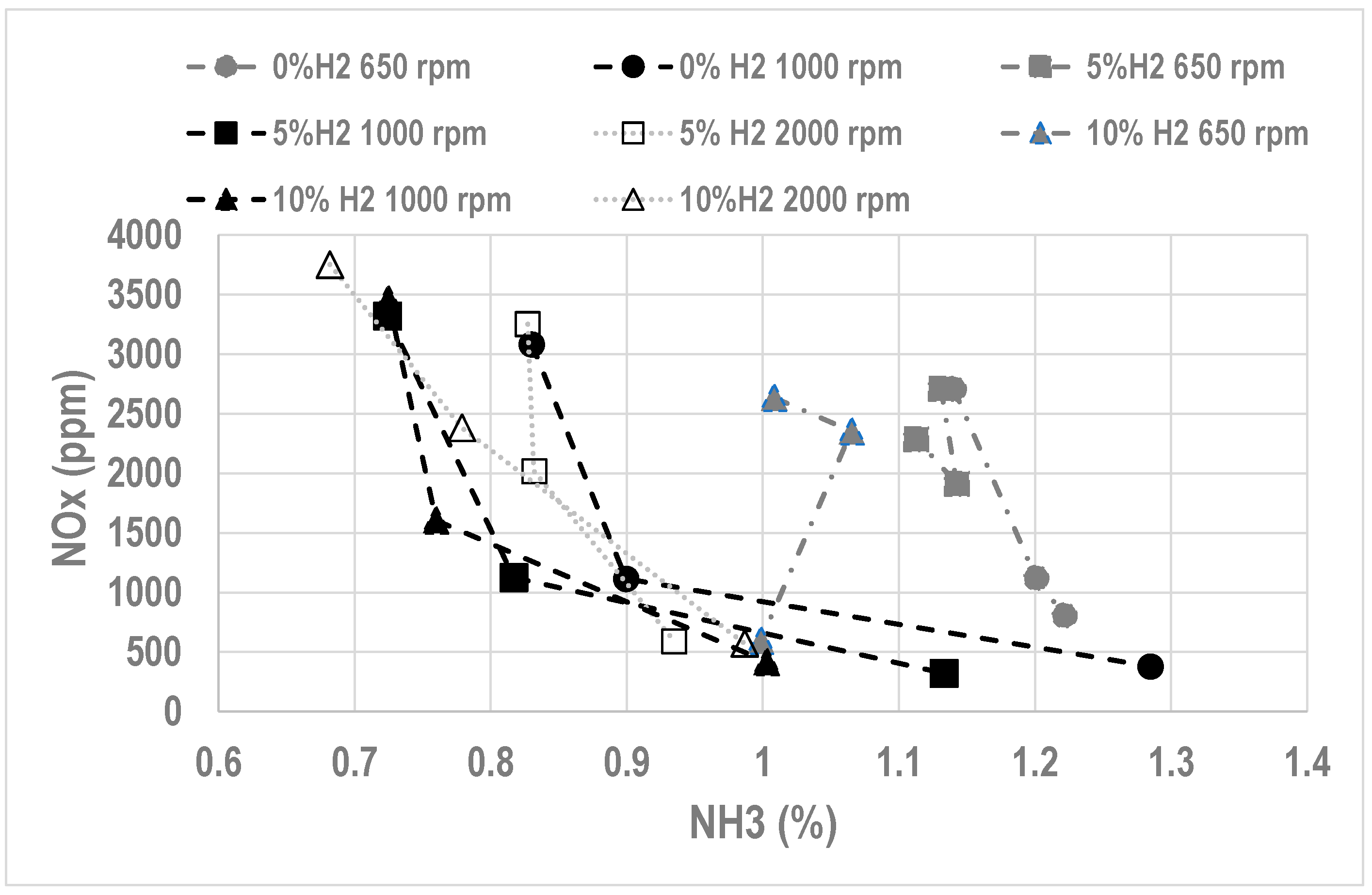
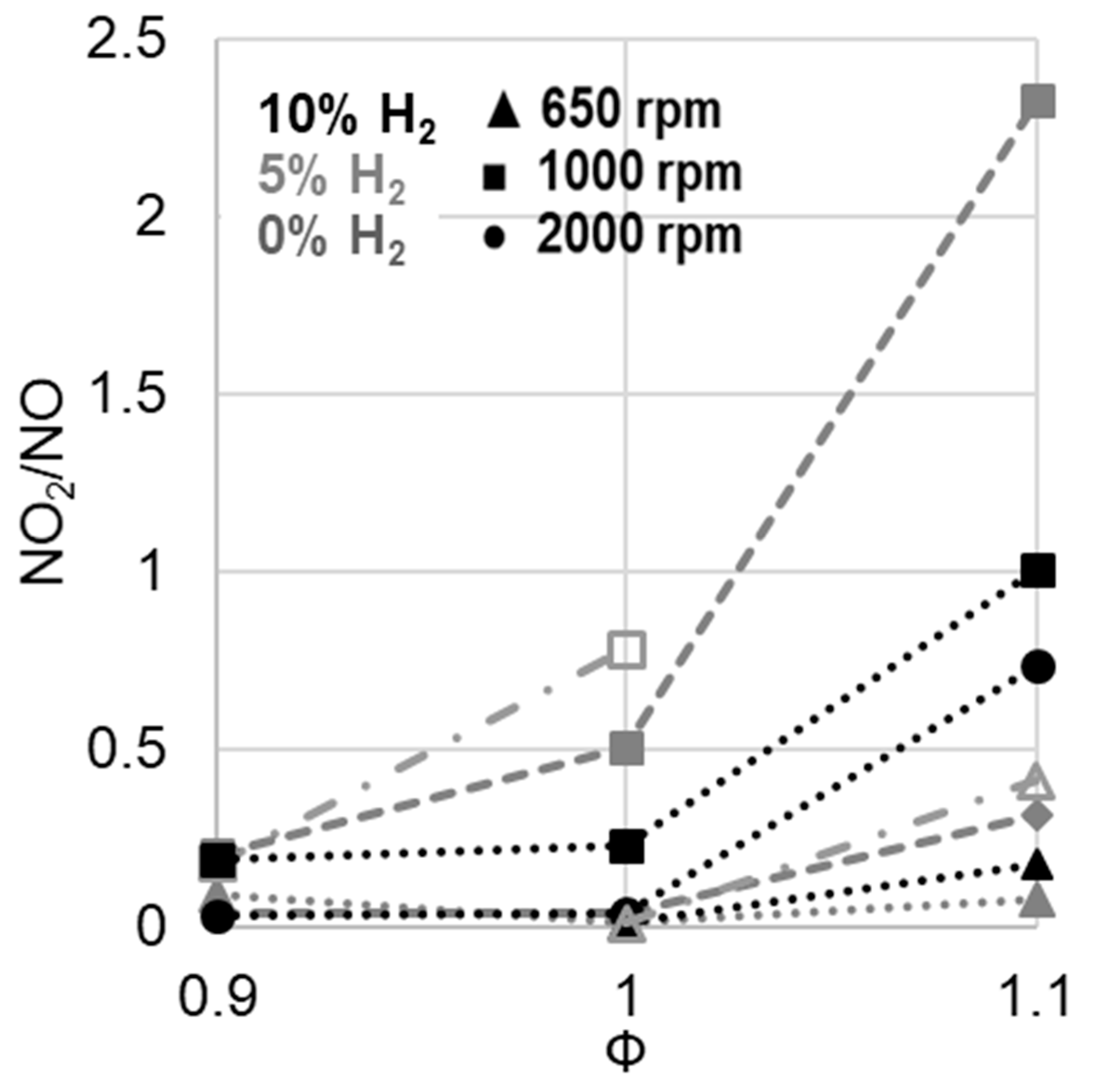
  • Lean operation leads to high NOx (higher than with gasoline) but low unburnt NH3
  • Rich operation leads to low NOx but too high unburnt NH3, unacceptable due to the smell and toxicity
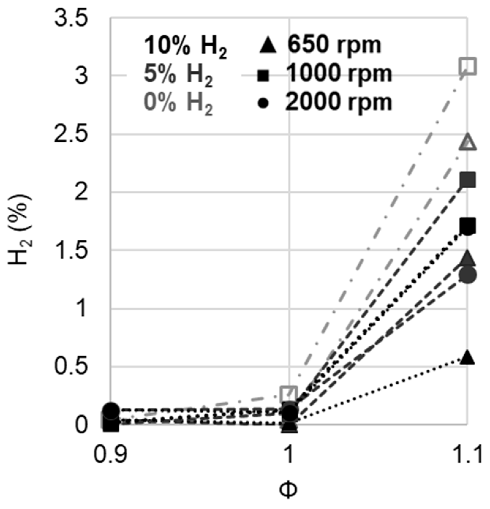
  • Increasing H2 quantity at the intake leads to a slightly higher NOx level, very low unburnt NH3 (due to a better combustion efficiency) but with some H2 content at the exhaust.
At this point, the optimization of the use of ammonia as fuel suffers from the limited data available on the performance of ammonia-fueled vehicles. Therefore, in order to increase the knowledge on ammonia fueled SI engine, the present paper will provide new data:
  • First, as a function of different engine speeds, with small H2 quantities at atmospheric intake pressure
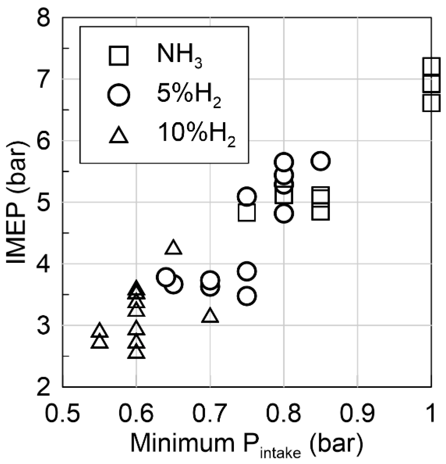
  • Second to determine the lowest acceptable intake pressure, i.e., load conditions,
  • And lastly, on a first evaluation of the possible dilution to limit pollutants for one particular condition (slight turbocharged conditions, fixed engine speed of 2000 rpm).

2. Experimental Methods

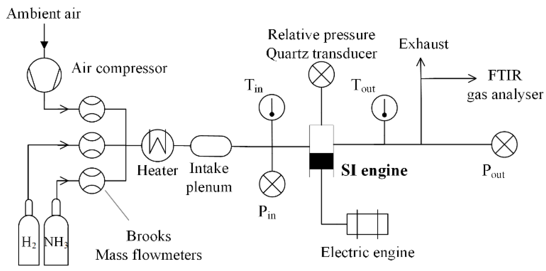
2.1. Experimental Set-Up

Engine experiments were conducted in a modern 4-cylinder 4-stroke Gasoline Direct Injection-SI EP6 PSA engine, modified to become an indirect injection single-cylinder engine by filling only 1 of 4 cylinders as fully described in [21]. The engine specifications are presented in Table 2.
The engine was driven by an electric motor at a fixed engine speed varied from 650 to 2000 rpm. The main shaft was equipped with an optical encoder for angular position monitoring with a 0.1 Crank Angle Degree (CAD) resolution. A water-cooled AVL piezoelectric pressure transducer with a 0.1 CAD resolution and a measuring range of 0–25 MPa provided in-cylinder pressure measurements. Engine intake and exhaust temperature and pressure were monitored using K-type thermocouples and piezo-resistive absolute pressure transducers. The absolute cylinder pressure was obtained by equalizing it with the mean absolute intake pressure, Pin, at 20 CAD after inlet valve opening. The spark plug device was the original one with a time discharge set to 2 ms.
Ammonia, hydrogen, and air gaseous flows were measured and controlled using Brooks thermal mass flowmeters with ±0.7% accuracy. They were preheated to the intake temperature of 323 K and premixed in an intake plenum before injection. A scheme of the experimental setup is shown in Figure 1.
The wet exhaust gases were analyzed using a Gasmet Fourier Transform Infrared (FTIR) spectrometer to assess H2O, NO, NO2, N2O, and NH3 concentrations. To obtain simultaneous quantitative measurement of many gaseous species with a good time resolution and accuracy, the interferences between the species of interest were correctly identified and considered in the analysis settings. The analysis ranges and uncertainty estimation can be found in previous work [30]. Please note that error bars were not plotted consistently in order to improve readability. In addition, analyzers for H2 by thermal conductivity and O2 by paramagnetic (ADEV) were used on a dry exhaust gas sample (without H2O and NH3). The water vapor measurement conducted with the FTIR analyzer was used for wet correction. The accuracy of the H2 and O2 analyzers was ± 1% (range 0–20% H2, 0–21% O2).

2.2. Investigated Conditions

The global stoichiometric reaction of NH3/H2/air complete combustion was, where x H 2 is the hydrogen molar fraction in the fuel mixture, as:
( 1 x H 2 ) N H 3 + x H 2 H 2 + 3 x H 2 4 ( O 2 + 3.76 N 2 ) ( 3 x H 2 2 ) H 2 O + ( 1 x H 2 2 + 3.76 3 x H 2 4 ) N 2
Non-stoichiometric mixtures are defined by the global equivalence ratio:
ϕ = X H 2 + X N H 3 X a i r ( X H 2 + X N H 3 X a i r ) s t
X s represents the molar fraction of the species, s, in the reactive mixture. The spark-ignition timing was set to ensure the maximum net indicated mean effective pressure (IMEP) with a coefficient of variation of the IMEP over 100 cycles, COVIMEP lower than 5%. Only averaged values over 100 cycles were presented in this paper. The range of investigated operating conditions is summarized in Table 3.

3. Results

3.1. Operating Limits

In Table 4, stable operation modes were identified with a cross and black cells indicate conditions where either ignition or stable operation (COVIMEP <= 5%) were possible. As can be seen, the addition of 10% H2 was sufficient to promote the ignition in all conditions. Increasing the engine speed makes the combustion for pure ammonia more difficult. Besides, it was not possible to ignite or ensure stable operations at 2000 rpm for pure ammonia. It was also more difficult to obtain stable combustion in lean conditions.
Figure 2 shows the IMEP as a function of the minimum intake pressure acceptable to ensure stable operation, i.e., COVIMEP <= 5%. Increasing H2 content in the fuel enables to operate at lower intake pressure down to 0.55 bar, which provides a 2.75 Bar IMEP. For pure ammonia, the minimum intake pressure achieved was 0.75 bar, corresponding to 4.8 bar IMEP. It was, therefore, possible to operate the engine at low load.

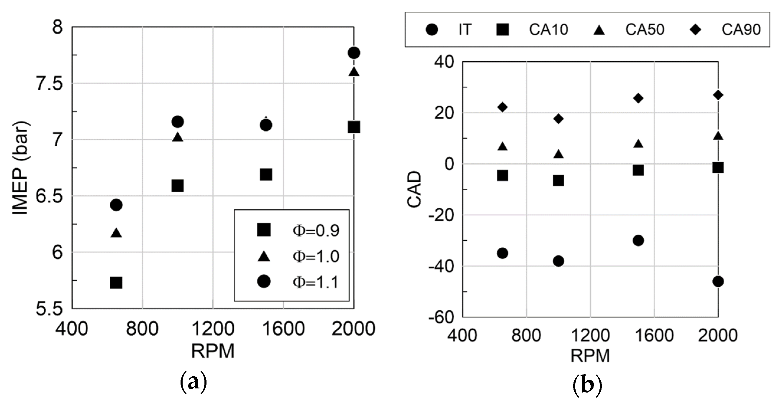
3.2. Engine Performance as a Function of Regime

Figure 3a shows the IMEP as a function of the engine speed for 10% H2 in the fuel, which guarantees stable operations in all conditions. One can notice the classical IMEP increase with engine speed at optimized Spark-Timing [31] due to improved combustion, less wall heat losses, and improved volumetric efficiency. Higher IMEP was obtained for stoichiometric and slightly rich mixture due to higher energy content. It seems that the IMEP peak value was not reached on this engine speed range consistently with the work of Cornelius et al. [9] that show the peak IMEP at 2500 rpm with a very similar CR. The indicated efficiency was around 28% for 650 rpm up to 35% for 2000 rpm for stoichiometric mixture. Ignition timing (IT) and Combustion phasing (CAX = Crank Angle Degrees, CAD, when X% of fresh fuel mass is burned) at the stoichiometric condition with 5% H2 in ammonia blend are plotted in Figure 3b. Similar combustion phasing and durations were displayed except for 2000 rpm, which had a much earlier spark timing. This phasing was set because of a very low flame speed compared to the engine speed: the flame required, therefore, more CAD to propagate in the cylinder.
Figure 4 presents NOx and NH3 emissions for three equivalence ratios and engine speeds for all H2 contents at atmospheric intake pressure. The maximum of NOx and NH3 correspond to 15g/kWh and 36 g/kWh, respectively, for 7 bars of IMEP. This maximum value of NOx, reached in lean air/fuel mixture, was about three times the level obtained with an engine fueled with gasoline. As expected, NH3 at exhaust increased with equivalence ratio when NOx decreases. The addition of H2 in ammonia induces an NH3 emission decrease at the exhaust, due to less NH3 as fuel at the intake, as expected, but also a slight improvement of the combustion efficiency, as for example, from 0.95 for neat ammonia to 0.96 with 10% H2 at the stoichiometry at 1000 rpm. The maximum NOx level was found in this study at Φ = 0.9 for all conditions. The decrease of NOx with equivalence ratio increase, as previously observed [23,24,25], was similar to NOx evolution for any hydrocarbons even if the NOx pathway was not only the thermal one. Indeed, there was also the fuel NO route due to the presence of N in the fuel molecule itself. This increased NOx level at the exhaust. Increasing the engine speed seemed to reduce NH3 level, but the effect on NOx was less evident. In their study, Frigo and Gentili [28] showed that the NOx level was almost constant as a function as the engine speed from 2500 to 4000 rpm, but it should be kept in mind that NH3/H2 ratio was optimized for each operating condition. Here, NOx increased globally with both engine speed and %H2 increase even if the engine speed effect was not so evident.
The plot of NO2/NO in Figure 5 indicates that NOx emissions were mainly composed of NO for lean and stoichiometric conditions. Minimum levels of NO2 were obtained at stoichiometry for 650 (about 20 ppm) and 2000 rpm (about 90 ppm). However, the highest values were measured at 1000 rpm (i.e., between 300 and 500 ppm) without any expected explanations. Increasing equivalence ratio decreased NO2 but less than for NO, thus increasing the proportion of NO2 in the NOx.
The combustion of NH3, due to the combustion kinetics and the presence of N in the fuel, can generate another product, N2O, which has a higher global warming potential than CO2 itself (i.e., 265 times higher). The evolution of N2O as a function of the equivalence ratio, plotted in Figure 6, presents the same trend as NOx emissions: the peak value was reached on the lean side, and the equivalence ratio increase induced emission decrease. For example, by considering an stoichiometric air/fuel mixture, as example at 1000 rpm, 30 ppm of N2O corresponded to 0.87% of CO2 as equivalent global warming impact, which represents 10% of CO2 emissions level for same engine fueling with an iso-octane/air stoichiometric mixture. It can also be noted that the increase of engine speed clearly increased N2O emissions (by 1.5), and the increase of H2 content seemed to also favor the production of N2O. As a result, the potential of NH3 as fuel in decreasing greenhouse gases emissions is here illustrated.
Due to the presence of H2 in some fuel blends but also to the local possible ammonia decomposition in the cylinder during the combustion phase, it was interesting to also follow H2 emissions, as displayed in Figure 7. As expected, H2 reaches an important level as unburnt gases of the fuel mixture up to 3% of total exhaust gases, in the case of rich fuel mixtures even for neat ammonia combustion. In that, in rich conditions, H2 emissions were even higher for ammonia only than for NH3-H2 blend. This was in agreement with the work of Cornelius et al. [9] and Lhuillier et al. [24]. In the case of lean and stoichiometric conditions, since the measured values were below the accuracy range of the analyzer, it indicated the total consumption of H2 as in [9,24]. The increase of engine speed seemed to lead to an increase of H2 emissions.
From the exhaust pollutants measurement, mitigation strategies for both NH3 and NOx were needed before considering ammonia as a fuel, acceptable for real applications. A Selective Catalyst Reactor (SCR) could be one solution since both heat and the NOx reducing agent, NH3 was available in the exhaust pipe, as suggested by Westlye et al. [17]. It has to be noticed first that NH3 content in the exhaust was for all conditions higher than NOx to allow SCR operating. The feasibility of that approach was assessed in Figure 8 where the average exhaust temperature is plotted as a function of the equivalence ratio. The highest exhaust temperatures were obtained for stoichiometric and slightly rich mixtures, where the maximum LBV was reached, thus bringing the operating conditions closer to an ideal cycle. As the optimum operating temperature for usual catalysts was in the range 280–480 °C, its correct operation has to be questioned at high speed and load. In the other hand, it has to be noted that the H2 content in the fuel (in the range studied) seems to have no impact on the exhaust temperature consistently with Lhuillier et al. results [23].
Nonetheless, before considering complicated post-exhaust systems, the use of exhaust gases recirculation (internal or external) can be explored for two main reasons: to limit NOx emissions, especially for lean operating mode, but also to improve the combustion development itself for rich ammonia/air mixture due to the addition of some small H2 contents in the exhaust gases. In the following, a dilution with N2 is considered only to evaluate how it could be one actuator to reduce NOx emissions without affecting the stability of the combustion itself in the case of pure ammonia (without any H2 content at the intake).

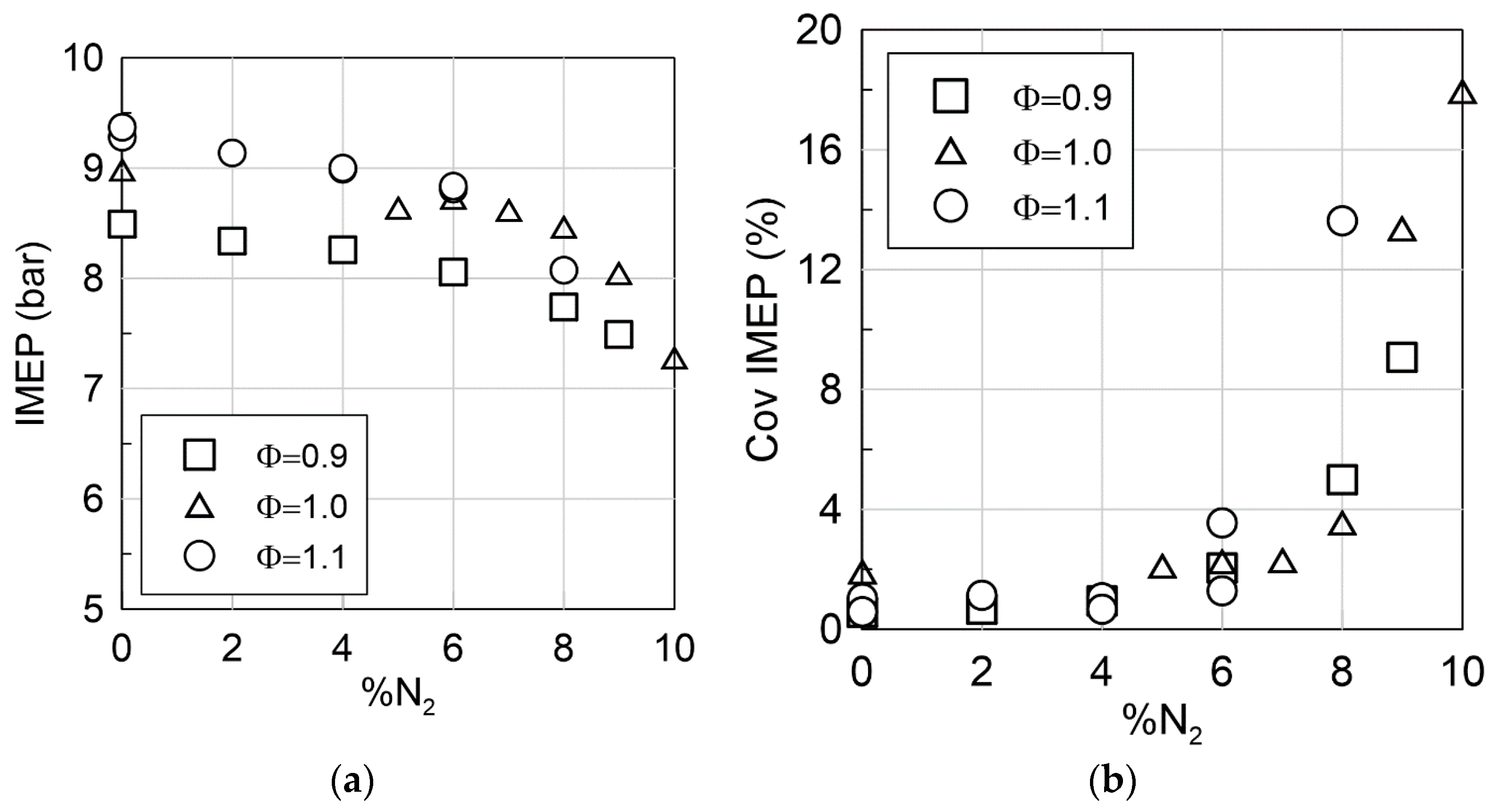
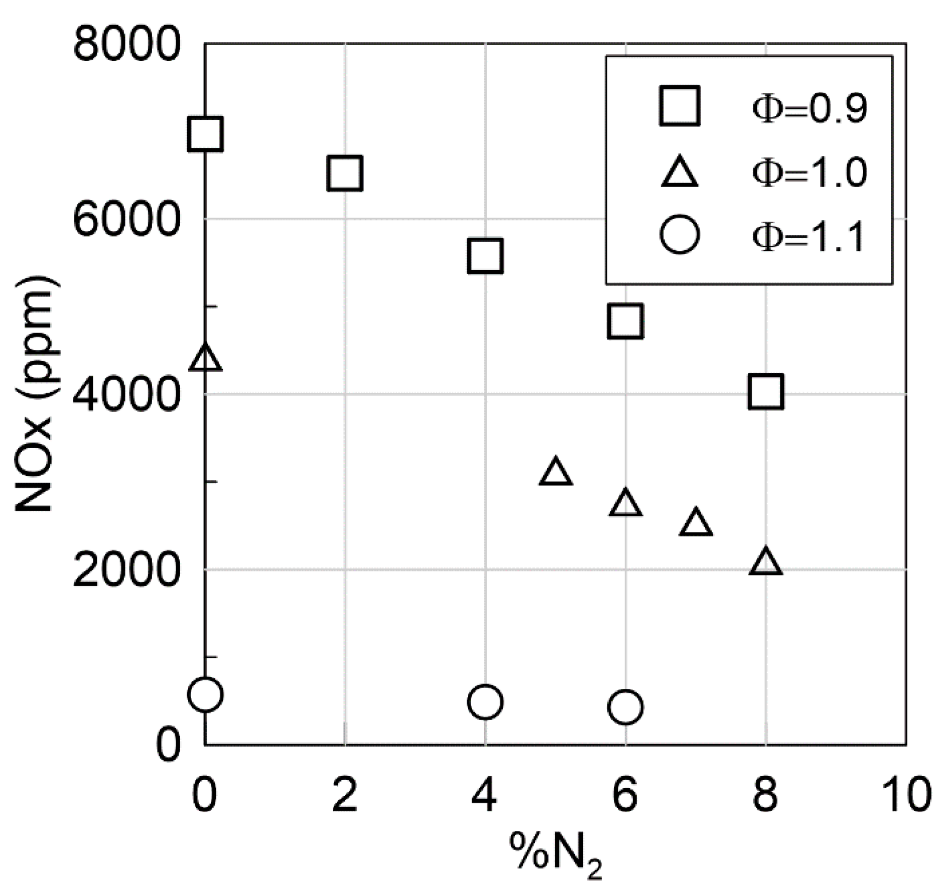
3.3. Dilution Opportunity @ 1500 rpm and Pin = 1.3 Bar

In order to simulate EGR, N2 was introduced at the intake in the case of ammonia as fuel only, for an intake pressure of 1.3 bar [25]. It was possible to ignite the air-NH3-N2 mixture up to N2 amount of 9% of the total intake air-fuel mixture, which corresponds to maximum 11% of intake air as an equivalent EGR. As shown in Figure 9, IMEP linearly decreases with %N2 (because of the lower energy content) up to 6–7% N2 where a drop occurs due to the stability limit that is reached as seen on the COVIMEP.
As expected, the combustion remains stable up to a certain percentage before COVIMEP explodes (about 8% N2) similar to hydrocarbon fuel [32]. Dilution shows interesting potential in reducing NOx at the exhaust, as it can be seen in Figure 10, especially on the lean side where a 40% decrease was observed with 8% N2 without increasing NH3 emissions. Real EGR could be even more interesting since it should contain unburned NH3 as well as potential H2 as seen above and in [24].

4. Conclusions

This paper has provided insights into operating with ammonia in a current GDI Spark-Ignition engine in terms of operating limit, engine speed effect, and dilution possibilities without any retrofit. Regarding the operating limits, it is clearly demonstrated that it is possible to run one engine at very low load as 2.75 bar IMEP, but when 10% H2 is added. On the other hand, the low loads can also be obtained at the idle speed (i.e., 650 rpm) even with neat ammonia as fuel. Globally, 10% H2 in the fuel guarantees all operating conditions possible. However, for neat ammonia, the low load operation is difficult with the compression ratio of 10.5, requiring a greater minimum intake pressure. The operation at 2000 rpm is also not possible due to the specific slow combustion speed of ammonia/air mixture. Combustion phasing appears to be not affected by the engine speed, but the ignition timing needs to be advanced for higher engine speed to guarantee sufficient time for the flame to propagate inside the cylinder.
Regarding the emissions, NH3 at the exhaust decreases with an engine speed increase, with highest levels reached for rich mixture. NH3 emissions for the leanest mixture (0.9) can reach 1% in vol, certainly due to the crevice trap. NOx emissions are mainly composed by NO and the effect of the engine speed seems to depend on the equivalence ratio. Even if NH3 does not produce any carbon content at the exhaust, it can emit N2O, one of the strongest greenhouse gases. Due to its very low emission level, the global warming potential represents only 2% equivalent of CO2 impact. For both NOx and N2O, the highest levels of emissions are observed on the lean side with a decrease with an equivalence ratio increase. Lastly, H2 is obtained at the exhaust in rich conditions even for neat ammonia combustion, indicating a local ammonia decomposition. Exhaust temperatures were also monitored and seemed suitable for SCR use to mitigate both NH3 and NOx emissions at least below 2000 rpm.
The last part of this study shows that dilution with N2 in turbocharged liked conditions is interesting in decreasing NOx at the exhaust, especially for lean and stoichiometric mixture even if only an equivalent EGR ratio lower than 10% is used to ensure combustion stability. As a result, there is interesting potential in studying operation with real EGR dilution as it should contain not only N2 and water but also H2, NOX, and NH3 with surely an impact on the chemistry and the thermodynamics.

Author Contributions

Methodology, all authors; investigation, C.M.-R., P.B.; resources, all authors. All authors have read and agreed to the published version of the manuscript.

Funding

This project receives support from the European Union’s Horizon 2020 research and innovation under grant agreement No. 862482 (ARENHA project).

Acknowledgments

The authors acknowledge the contribution of B. Raitière and J. Bouriot, from joint PRISME/PSA Open lab ‘Energetics’, for their technical support.

Conflicts of Interest

The authors declare no conflict of interest.

References

  1. Valera-Medina, A.; Xiao, H.; Owen-Jones, M.; David, W.I.F.; Bowen, P.J. Ammonia for power. Prog. Energy Combust. Sci. 2018, 69, 63–102. [Google Scholar] [CrossRef]
  2. Valera-Medina, A.; Amer-Hatem, F.; Azad, A.K.; Dedoussi, I.C.; de Joannon, M.; Fernandes, R.X.; Glarborg, P.; Hashemi, H.; He, X.; Mashruk, S.; et al. Review on Ammonia as a Potential Fuel: From Synthesis to Economics. Energy Fuels 2021, 35, 6964–7029. [Google Scholar] [CrossRef]
  3. AWijayanta, A.T.; Oda, T.; Purnomo, C.W.; Kashiwagi, T.; Aziz, M. Liquid hydrogen, methylcyclohexane, and ammonia as potential hydrogen storage: Comparison review. Int. J. Hydrog. Energy 2019, 44, 15026–15044. [Google Scholar] [CrossRef]
  4. Linstrom, P.J.; Mallard, W.G. NIST Chemistry WebBook, NIST Standard Reference Database Number 69, 20899; National Institute of Standards and Technology: Gaithersburg, MD, USA, 2018. [Google Scholar] [CrossRef]
  5. Mørch, C.; Bjerre, A.; Gøttrup, M.; Sorenson, S.; Schramm, J. Ammonia/hydrogen mixtures in an SI-engine: Engine performance and analysis of a proposed fuel system. Fuel 2011, 90, 854–864. [Google Scholar] [CrossRef]
  6. Bicer, Y.; Dincer, I. Life cycle assessment of ammonia utilization in city transportation and power generation. J. Clean. Prod. 2018, 170, 1594–1601. [Google Scholar] [CrossRef]
  7. Koch, E. Ammonia as a fuel for motor buses. J. Inst. Pet. 1949, 31, 21–32. [Google Scholar]
  8. Gray, J.T.; Dimitroff, E.; Meckel, N.T.; Quillian, R.D. Ammonia Fuel—Engine Compatibility and Combustion. SAE Tech. Pap. 1966. [Google Scholar] [CrossRef]
  9. Cornelius, W.; Huellmantel, L.W.; Mitchell, H.R. Ammonia as an Engine Fue. SAE Tech. Pap. 1965. [Google Scholar] [CrossRef]
  10. Starkman, E.S.; Newhall, H.K.; Sutton, R.; Maguire, T.; Farbar, L. Ammonia as a Spark Ignition Engine Fuel: Theory and Application. SAE Tech. Pap. 1966. [Google Scholar] [CrossRef]
  11. Starkman, E.S.; James, G.E.; Newhall, H.K. Ammonia as a Diesel Engine Fuel: Theory and Application. SAE Tech. Pap. 1967. [Google Scholar] [CrossRef]
  12. TPearsall, J.; Garabedian, C.G. Combustion of Anhydrous Ammonia in Diesel Engines. SAE Tech. Pap. 1967. [Google Scholar] [CrossRef]
  13. Sawyer, R.F.; Starkman, E.S.; Muzio, L.; Schmidt, W.L. Oxides of Nitrogen in the Combustion Products of an Ammonia Fueled Reciprocating Engine. SAE Tech. Pap. 1968. [Google Scholar] [CrossRef]
  14. Garabedian, C.; Johnson, J. The Theory of Operation of an Ammonia Burning Internal Combustion Engine, Report 634681; MI, USA, 1965; Available online: https://apps.dtic.mil/sti/citations/AD0634681 (accessed on 7 July 2021).
  15. Dimitriou, P.; Javaid, R. A review of ammonia as a compression ignition engine fuel. Int. J. Hydrog. Energy 2020, 45, 7098–7118. [Google Scholar] [CrossRef]
  16. Mounaïm-Rousselle, C.; Brequigny, P. Ammonia as Fuel for Low-Carbon Spark-Ignition Engines of Tomorrow’s Passenger Cars. Front. Mech. Eng. 2020, 6, 70. [Google Scholar] [CrossRef]
  17. Westlye, F.R.; Ivarsson, A.; Schramm, J. Experimental investigation of nitrogen based emissions from an ammonia fueled SI-engine. Fuel 2013, 111, 239–247. [Google Scholar] [CrossRef]
  18. Grannell, S.M.; Assanis, D.N.; Bohac, S.V.; Gillespie, D.E. The Fuel Mix Limits and Efficiency of a Stoichiometric, Ammonia, and Gasoline Dual Fueled Spark Ignition Engine. J. Eng. Gas Turbines Power 2008, 130, 042802. [Google Scholar] [CrossRef]
  19. Grannell, S.M.; Assanis, D.N.; Gillespie, D.E.; Bohac, S.V. Exhaust Emissions From a Stoichiometric, Ammonia and Gasoline Dual Fueled Spark Ignition Engine. In Proceedings of the ASME International Combustion Engine Division 2009 Spring Tech. Conf., Milwaukee, WI, USA, 3–6 May 2009. [Google Scholar] [CrossRef]
  20. Ryu, K.; Zacharakis-Jutz, G.E.; Kong, S.-C. Performance enhancement of ammonia-fueled engine by using dissociation catalyst for hydrogen generation. Int. J. Hydrog. Energy 2014, 39, 2390–2398. [Google Scholar] [CrossRef]
  21. Ryu, K.; Zacharakis-Jutz, G.E.; Kong, S.-C. Effects of gaseous ammonia direct injection on performance characteristics of a spark-ignition engine. Appl. Energy 2014, 116, 206–215. [Google Scholar] [CrossRef]
  22. Koike, M.; Miyagawa, H.; Suzuoki, T.; Ogasawara, K. Ammonia as a hydrogen energy carrier and its application to internal combustion engines. In Sustainable Vehicle Technologies; Warwickshire, G., Ed.; Woodhead Publishing: Cambridge, UK; pp. 61–70. [CrossRef]
  23. Lhuillier, C.; Brequigny, P.; Contino, F.; Mounaïm-Rousselle, C. Experimental study on ammonia/hydrogen/air combustion in spark ignition engine conditions. Fuel 2020, 269, 117448. [Google Scholar] [CrossRef]
  24. Lhuillier, C.; Brequigny, P.; Contino, F.; Rousselle, C. Performance and Emissions of an Ammonia-Fueled SI Engine with Hydrogen Enrichment. SAE Tech. Pap. 2019. [Google Scholar] [CrossRef]
  25. Lhuillier, C.; Brequigny, P.; Contino, F.; Rousselle, C. Combustion Characteristics of Ammonia in a Modern Spark-Ignition Engine. SAE Tech. Pap. 2019. [Google Scholar] [CrossRef]
  26. Woo, Y.; Jang, J.Y.; Lee, Y.J.; Kim, J.N. Recent progress on the Ammonia-Gasoline and the Ammonia-Diesel Dual Fueled Internal Combustion Engines in Korea. In Proceedings of the 11th Annual NH3 Fuel Conferences, Des Moines, IA, USA, 22 September 2014. [Google Scholar]
  27. Haputhanthri, S.O.; Maxwell, T.T.; Fleming, J.; Austin, C. Ammonia and Gasoline Fuel Blends for Spark Ignited Internal Combustion Engines. J. Energy Resour. Technol. 2015, 137, 062201. [Google Scholar] [CrossRef]
  28. Frigo, S.; Gentili, R. Analysis of the behaviour of a 4-stroke Si engine fuelled with ammonia and hydrogen. Int. J. Hydrog. Energy 2013, 38, 1607–1615. [Google Scholar] [CrossRef]
  29. Comotti, M.; Frigo, S. Hydrogen generation system for ammonia-hydrogen fuelled internal combustion engines. Int. J. Hydrog. Energy 2015, 40, 10673–10686. [Google Scholar] [CrossRef]
  30. Lhuillier, C.; Brequigny, P.; Lamoureux, N.; Contino, F.; Mounaïm-Rousselle, C. Experimental investigation on laminar burning velocities of ammonia/hydrogen/air mixtures at elevated temperatures. Fuel 2020, 263, 116653. [Google Scholar] [CrossRef] [Green Version]
  31. Heywood, J.B. Internal Combustion Engine Fundamentals, 2nd ed.; McGraw-Hill Education: New York, NY, USA, 2018; Available online: https://www.accessengineeringlibrary.com/content/book/9781260116106 (accessed on 7 July 2021).
  32. Francqueville, L.; Michel, J.-B. On the Effects of EGR on Spark-Ignited Gasoline Combustion at High Load. SAE Int. J. Engines 2014, 7, 1808–1823. [Google Scholar] [CrossRef]
Figure 1. Layout of the experimental setup.
Energies 14 04141 g001
Figure 2. IMEP vs minimum intake Pressure.
Energies 14 04141 g002
Figure 3. IMEP (a) and combustion phasing (b) vs. engine speed at Pin = 1 bar and 10% H2 (Φ = 1). 1500 rpm from [23].
Energies 14 04141 g003
Figure 4. NOx emissions vs NH3 emissions for %H2 content (0.5 and 10), 3 engine speeds and equivalence ratio. Pin = 1 bar.
Energies 14 04141 g004
Figure 5. NO2/NO emissions vs equivalence ratio for different engine speeds and H2 content, Pin = 1 bar.
Energies 14 04141 g005
Figure 6. N2O emissions vs equivalence ratio for different engine speeds and H2 content, Pin = 1 bar.
Energies 14 04141 g006
Figure 7. H2 emissions vs equivalence ratio for different engine speeds and H2 content in the fuel. Pin = 1 bar.
Energies 14 04141 g007
Figure 8. Exhaust temperature vs equivalence ratio. Pin = 1 bar.
Energies 14 04141 g008
Figure 9. IMEP (a) and COV IMEP (b) vs %N2 in total intake gases for pure ammonia, Pin = 1.3 bar, 1500 rpm.
Energies 14 04141 g009
Figure 10. NOx vs. %N2 in total intake gases for pure ammonia. Pin = 1.3 bar, 1500 rpm.
Energies 14 04141 g010
Table 1. Ammonia properties and comparison with other fuels at 300 K and 0.1 MPa, unless stated otherwise.
SpeciesAmmoniaMethanolHydrogenMethaneGasoline
FormulaNH3CH3OHH2CH4-
StorageLiquidLiquidCompressedCompressedLiquid
Storage temperature (K)300300300300300
Storage pressure (MPa)1.10.170250.1
density @ storage conditions (kg.m−3)600784.639.1187~740
FL in air (vol.%)15–286.7–364.7–755–150.6–8
LBV @ stoichiometry (m.s−1)0.070.363.510.380.58
Auto-ignition T (K)930712773–850859503
Research Octane Number130119>10012090–98
LHV (MJ/kg)18.819.91205044.5
Table 2. Engine specifications.
Displaced Volume399.5 cm3
Stroke85.8 mm
Bore77 mm
Connecting rod length138.5 mm
Compression ratio10.5:1
Number of valves4
Table 3. Overview of the test conditions.
Engine Speed (rpm)650; 1000; 1500; 2000
Intake temperature (K)323
Intake pressure (bar)[0.6–1] 1.3 for dilution impact
H2 molar fraction in the fuel, x H 2 [0.0–0.10]
ϕ [0.9–1.1]
%N2 dilutionUp to 8% of the total at the intake
Table 4. Limits in operating the engine with ammonia for several engine speeds, equivalence ratios, percentages of H2 as a function of intake pressures.
650 rpm1000 rpm1500 rpm2000 rpm
%H2
ΦPin (bar)0%5%10%0%5%10%0%5%10%0%5%10%
0.9<=0.65 X X X X
0.8–0.85 XXXXX XX X
1 XXXXXXXX XX
1<=0.65 X XX X X
0.8–0.85XXXXXX XX XX
1XXXXXXXXX XX
1.1<=0.65 X XX X X
0.8–0.85XXXXXX XX XX
1XXXXXXXXX XX
Publisher’s Note: MDPI stays neutral with regard to jurisdictional claims in published maps and institutional affiliations.

