Article

Dynamic Stability of Wind Power Flow and Network Frequency for a High Penetration Wind-Based Energy Storage System Using Fuzzy Logic Controller

by
Md Jahidur Rahman
1,*,
Tahar Tafticht
1,
Mamadou Lamine Doumbia
2 and
Ntumba Marc-Alain Mutombo
3
1
Department of Engineering, Université du Québec en Abitibi-Témiscamingue, Rouyn-Noranda, QC J9X 5E4, Canada
2
Department of Electrical and Computer Engineering, Université du Québec à Trois-Rivières, Trois-Rivières, QC G8Z 4M3, Canada
3
Department of Electrical Engineering, Mangosuthu University of Technology, Durban 4031, South Africa
*
Author to whom correspondence should be addressed.
Energies 2021, 14(14), 4111; https://doi.org/10.3390/en14144111
Submission received: 15 June 2021 / Revised: 1 July 2021 / Accepted: 3 July 2021 / Published: 7 July 2021
(This article belongs to the Section A3: Wind, Wave and Tidal Energy)

Abstract

:
Major changes in the technologies of power generation and distribution systems have been introduced in recent years due to concern over rapid climate change. Therefore, disturbances in the large-scale generation, transmission, and distribution of energy are expected to occur in the near future. This is due to the difficulty in controlling the transmission and distribution of energy produced from renewable energy sources (RESs), caused by the instability of these sources and the intermittent nature of their energy. As a result, maintaining the dynamic stability of wind power flow and control of the network frequency is becoming more challenging due to the high penetration impacts of RESs. In this paper, a control algorithm using the power-sharing method is proposed for a wind-based energy storage system to maintain the dynamic stability of wind power flow and control of frequency in the power network. To maintain the network stability, a storage system (battery) was installed to store the excess wind power without throwing it into the Secondary/Dump Load (SL) and minimize losses in power generated by the wind turbine. The results show, the transient time of wind power flow and the fluctuation rate of frequency are reduced significantly using a Fuzzy Logic (FL) controller compared to the Proportional Integral Derivative (PID) controller.

Graphical Abstract

1. Introduction

In recent years, the percentage of renewable energies on power grids has increased significantly. This rise was prompted by policies aimed at combating climate change and securing a sustainable energy supply. The Intergovernmental Panel on Climate Change (IPCC) reported that: “the production of greenhouse gases, such as nitrous oxide (N2O), carbon dioxide (CO2) and methane (CH4) are responsible for global warming due to the evolution of fossil fuels” [1]. The replacement of fossil energy sources by renewable energy sources (RESs) such as wind, solar, biomass, hydroelectricity, etc., and their integration into low and high voltage electrical networks is currently the subject of research in several countries such as the United States, Canada, Germany, and China.
Concerns about climate change caused by the usage of fossil fuels have made renewable energy one of the most popular research topics [2]. Around 23.7 percent of the world’s power is produced by RE. This implies that renewable energy accounts for a quarter of global power generation, with photovoltaic (PV) and wind turbine (WT) systems accounting for 77% of new renewable energy installations [2]. The main focus in renewable energy is on microgrids, which are hybrid renewable energy systems that are the subject of intense investigation. A microgrid is a system that produces clean, sustainable, steady, and dependable electricity by combining renewable resources with one or more conventional power sources [3]. They can be connected to the grid or run independently [2]. Due to the requirement for a control system to efficiently manage the operation of intermittent renewable resources, an energy management system is generally included inside a microgrid [4]. This is mainly achieved by including an energy storage system to increase the effectiveness and stability of the microgrid.
Recently, several studies have been implemented a fuzzy logic controller to employ Enegy Management Systems (EMS) on Microgrids. Due to its ability to handle many tasks effectively and forecast wind speed, solar radiation, load usage, and even the grid’s health, fuzzy logic is an effective microgrid control, particularly when several functions are performed on the microgrid [2]. It can regulate many operations in the microgrid, including load shedding, energy cost reductions, and CO2 emissions [5].
Several studies in the literature used Fuzzy Logic Energy Management System (FLEMS) to regulate the level of charge of battery energy storage in microgrids of various topologies in order to extend their lifetime and provide smooth operation [2]. The lifespan of the battery for a microgrid constituted of PV, WT, and Battery Energy Storage (BES), and supplying different sorts of loads, can be increased by maintaining the State of Charge (SOC) of the batteries using FLEMS [6,7]. Considerable achievement in battery lifespan can also be made by estimating the Fuel Cell (FC) electrolyser and battery power based on the batteries’ SOC and the FC’s hydrogen tank level using FLEMS for a standalone microgrid equipped with PV, WT, battery storage, and a FC [8,9]. A FLEMS can also be used to maximize hydrogen production and optimize power flow and generation in a microgrid composed of PV, FC and BESS controlled by FLEMS [10]. Furthermore, the grid power profile can be smoothed in a grid-connected AC microgrid while maintaining the SOC of the BESS with the lowest possible fuzzy logic rules using an FLMS [11].
Maintaining the SOC of battery storage is one of the key issues of building the EMS of microgrids of various topologies, as we can see from past research. According to the research, there are several benefits to using intelligence methods to optimize the FLEMS of various microgrid topologies [2]. FLEMS optimization allows for more accurate control, resulting in more efficient operation, reduced backup system costs, and a more balanced operation between generation and consumption [2]. A number of studies have been published that have improved the FLEMS of microgrids. Many optimization approaches for microgrids FLEMS have been utilized. Particle swarm optimization (PSO) [12,13,14], genetic algorithm (GA) optimization technique [15], seeker optimization approach (SOA) [16], and ABC optimization technique [17,18] are all examples of this.
One of the most popular forms of renewable energy today is wind energy [19,20]. However, the stochastic nature of this energy makes it difficult to integrate it into the power grid, especially when it comes to large-scale integration into Voltage Source Converter-based High Voltage Direct Current (VSC-HVDC) power grids. In addition, perfect synchronization is required to improve power quality as well as the frequency for keeping the network stable and robust. The globalization of electricity sectors, which was initiated a few years back, allows the improvement of new technologies of power generation. Some small-scale productions of RESs may not be equipped with the transmission lines of electricity [21,22]. The connection of RESs is made straight to the distribution side of the grid and the microgrid defined as a Distributed Generation (DG). The new prospect with this type of energy production makes it challenging, which is considered the top area of study in power system generation.
DG is mainly connected with the same transmission network which is maintained from the central station. Therefore, different technical problems arise associated with protection, reliability, harmonics, energy storage, and control systems [21,22,23,24]. Due changes in the environmental parameters, it is difficult to have continuous power generation from RESs. The fluctuating nature of power generated from these systems, wind in particular [25], makes it difficult to control, balance, and demand their energy. As a result, the dynamic stability of network frequency is becoming more challenging due to the high penetration impacts of RESs. Under these conditions, many scientists have taken attempts to find and investigate the main constraints that might happen throughout the connection made between the power grid and DG. The impacts of one non-renewable and two renewable types of DG on voltage profiles and power losses on a distribution network were examined [26]. The conclusion was different types of DG differently influence the distribution network, and their precise location and size are vital in reducing power losses and improving voltage stability. Consequently, new mechanisms to analyze the nature of the variables involved in the new power network such as power stability, current, voltage, and frequency fluctuations have been established [21,22,23,27,28]. To improve these variables, many researchers made efforts to develop the power network control schemes in their pioneer research. Most of the controllers are based on classical control techniques such as Proportional Integral Derivative (PID), and Artificial Intelligence Control Techniques such as Genetic Algorithm, Fuzzy Logic, Neural Network, Particle Swarm, and Linear Quadratic Regulator Control Techniques [29,30]. To investigate these types of control strategies on DG-based power systems, literature was carried out to gather information and investigate the dynamic stability of power flow and fluctuation behavior of frequency caused by the high penetration of RESs into the grid. To keep the acceptable frequency level in a DG-based power generation system, the excess power produced by the RESs compared to the total load demand needs to be thrown in the Secondary/Dump Load (SL). This has been found to be one of the main drawbacks for a future power plant system [31,32,33]. In this paper, a technical rule to store excess energy from the wind turbine and supply it to the grid in case of power shortage is proposed. The stability of wind power flow depends upon the natural situation. Therefore, to improve the wind power flow and reduce the frequency fluctuation of the network, a new control strategy has been developed and proposed to minimize the transient time of wind power flow as well as the fluctuation behavior of frequency in the grid. This is achieved by increasing the high penetration of DG using PID and fuzzy logical controllers.
The contributions of this paper are summarized as follows:
  • Designing of a control scheme to share the power between the networks using a logical algorithm;
  • Regulation of the network frequency using a storage system;
  • Reduction of the transient time of wind power flow and the fluctuation behavior of frequency using a fuzzy logical controller;
  • Storing the surplus wind power and maintaining a high load demand by supplying it into the network;
  • Comparing the robustness of the fuzzy logic controller over the PID controller to reduce the fluctuation behavior of frequency in the network.
The rest of the paper is organized as follows: Section 2 describes the modeling of thr distributed generation grid. Section 3 provides the control algorithm formulation for a Wind–Diesel Hybrid Power System (WDHPS). Section 4 highlights the control techniques applied to the network. Section 5 presents the tested scheme connected with a WDHPS to a power network using a battery-based storage system. Simulation results and performance evaluations of the proposed method are presented in Section 6, and Section 7 concludes the paper.

2. Modeling of Distributed Generation Grid
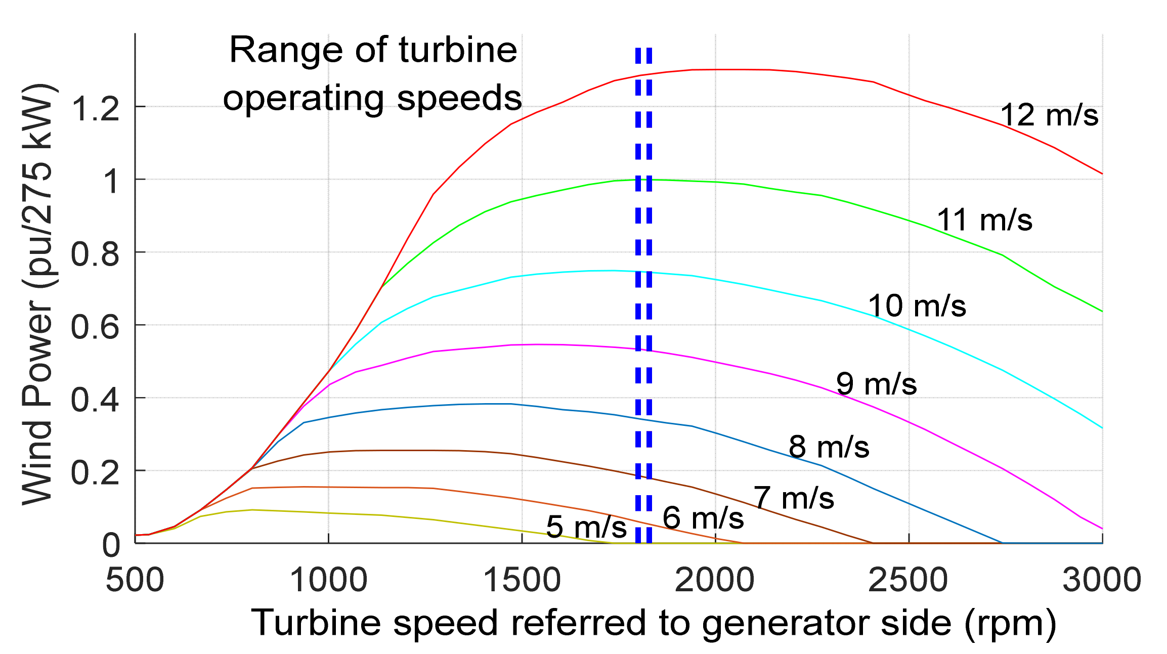
2.1. Wind Turbine

The wind turbine is equipped with an Asynchronous Machine (ASM), with a rated power of 480 kVA with an inertia of 2 s. The wind DG helps to produce a wind power Pwind to regulate the velocity of rotation of the ASM shaft to determine its mechanical torque. Here, the DG is operated at a constant velocity (10 m/s) of the wind power generator. Thus, it does not have control over its pitch angle [34]. As a function of turbine speed and wind speed, a 2-D lookup chart is used to measure the output of the turbine torque (Tm). The characteristics of the wind turbine are presented in Figure 1.

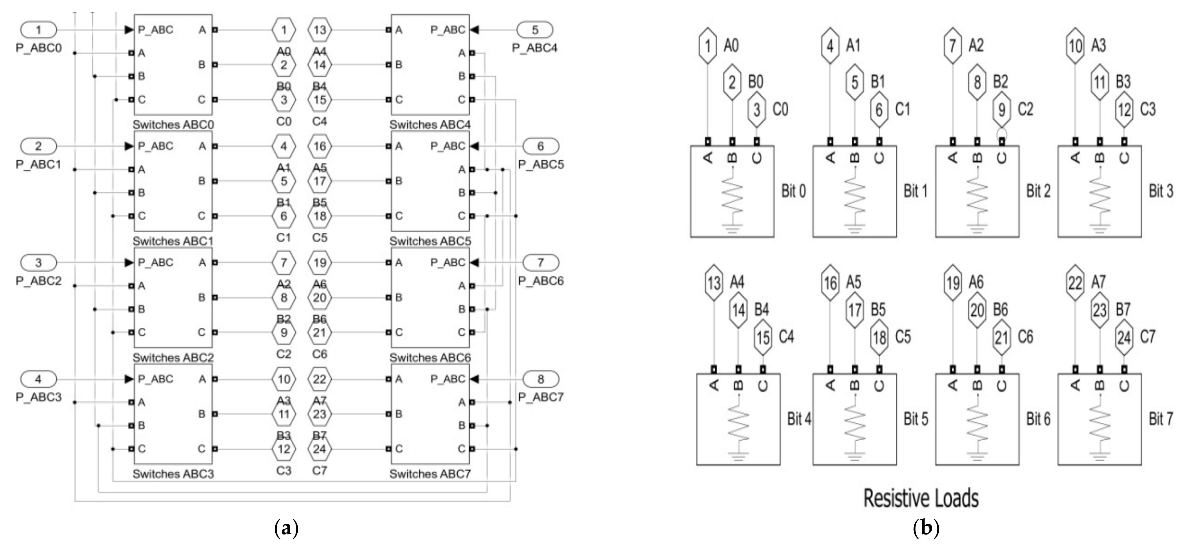
2.2. Secondary/Dump Load System

The Secondary Load (SL) helps to control the system frequency by absorbing the excess wind energy corresponding to the consumer demand. It consists of three-phase eight sets of resistors grouped in series with Gate turn-off thyristor switches (GTO), shown in Figure 2a. The nominal power of all sets of resistors, shown in Figure 2b, maintains binary (8 bit) advancement to absorb the wind power by the SL. The resistive loads can be varied from 0 to 446.25 kW by steps of 1.75 kW. The SL is only designed to control the fluctuation of frequency in the power grid by consuming the power produced by the wind turbine that the battery cannot store [23,27]. GTOs are simulated by ideal switches.

2.3. Battery-Based Energy Storage System

A Battery-based Energy Storage System (BESS) with a power converter is shown in Figure 3a. The BESS is composed of a battery bank. The power (PS-NAME = 150 kW) of a bridge bidirectional Insulated Gate Bipolar Transistor (IGBT) is regulated in the current mode. The role of the IGBT is to convert the DC sources to the AC sources in the BESS interface connecting with an isolated power network. The BESS rated capacity is 390 Ah with a voltage of 240 V, which can charge and discharge the BESS corresponding to the load demand of the power network. The control scheme of the Current Controlled Inverter (CCI) is shown in Figure 3b. The control technique of CCI is carried out in a structure of rotating dq-coordination. A Phase-Locked Loop (PLL) is used to follow the waveform of grid voltage that provides the reference for the coordinate of dq-abc and abc-dq transformation. The output of the CCI current is calculated and transformed in the rotating frame as well as the currents (both active and reactive) regulated in four quadrants using a Proportional Integral (PI) controller. According to the rating of the proportional gain Kp = 1, the integral gain Ki = 200, and sample time 50 μs, the response time of the CCI is less than 1 min/s. Therefore, the control of frequency becomes very fast in the power grid [35]. An LC filter is connected in the CCI to minimize the current ripples. A step-down transformer rated 120 kV/480 V, 150 kVA is used to connect the BESS with an isolated network.

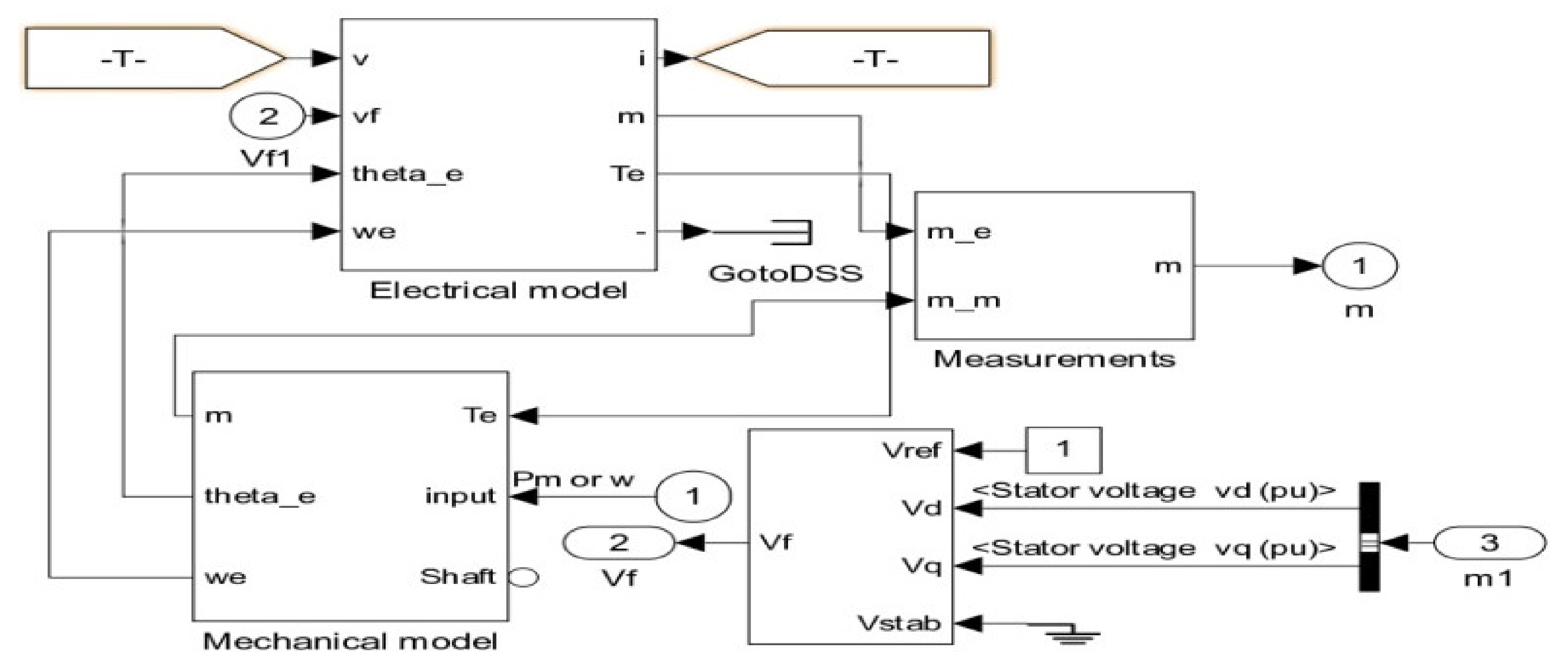
2.4. Synchronous Condenser

A synchronous condenser (nominal rated power of 300 kVA) generates the voltage signal to regulate the network voltage when the diesel engine is shut down. The voltage regulator of the synchronous condenser regulating the excitation of the condenser to supply the reactive power at a nominal voltage level at different buses is shown in Figure 4. Here, the primary task of the synchronous condenser is to supply the reactive power in the DG network [36,37].
Parameters of the WDHPS network with BESS systems are presented in Table 1.

3. Control Algorithms for WDHPS

The principle of dynamic stability of wind power flow and the control technique of frequency in the WDHPS network is presented by a logical algorithm shown in Figure 5.
To secure the performance of the WDHPS, the system needs an effective control scheme by using the optimum operating mode to avoid any interruption that occurs during the wind power flow as well as in the frequency of the network. Therefore, two types of control schemes should be considered: one is to ensure the dynamic stability of the power network and reduce the frequency of fluctuations while another is to fulfill the energy demand with the BESS logical algorithm.

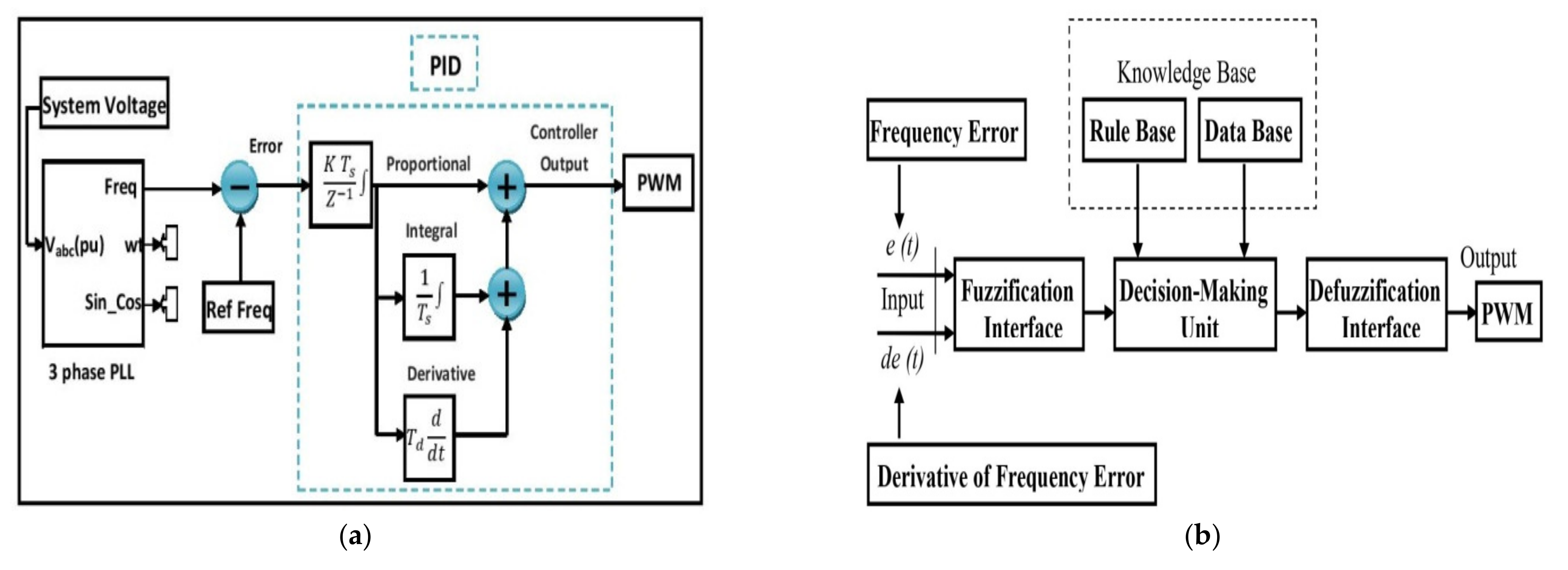
3.1. Control Technique of Frequency in the WDHPS Network

To regulate the network frequency, an instantaneous level of active power must be generated and consumed by the loads. To maintain the desired level of wind power flow in the network, the SL absorbs the active power that the BESS cannot store due to its capacity limitations [27,29,38,39,40]. In this situation, PT > PL, when PS > 0. Where PS: BESS supplied power; PT: wind turbine generated power; PL: load consumed power. In case the BESS supplies the energy to the WDHPS, PT < PL when PS < 0. Here, all the surplus wind energy is absorbed by the SL, 0 < PSL. It can be written as:
P T P L P S L P S = J ω   d ω d t
where PSL denotes the power absorbed by the SL and J is the inertia of the system,
ω = 2   π   f / p
where ω is the velocity (rad/s) of the synchronous machine shaft; p is the poles number of the synchronous machine. The losses in Equation (1) are not being considered in this case. Thus, PS < PS_nom and PSL < PSL_nom (converter nominal value). To keep a steady-state velocity of ASM, we can write:
d ω d t = 0
The control strategy of the BESS and SL systems should be coordinated with each other. The SL should consume the surplus wind power that the BESS cannot store. Therefore, Equation (1) can be written as:
P T P L = P S L + P S
P r e f = P S r e f + P S L r e f
P S L r e f = 0   w h e n   P r e f < P S n o m
Equation (5) becomes PSL_ref = Pref, if the BESS reaches its maximum capacity (PS_ref). The SL helps to absorb the wind power if Pref is more than the BESS nominal power. The PS-Max varies between 0 and PS_nom, by using a Positive Power Limit (PPL) signal. The power shared between the BESS and the SL is determined by the priority of power consumption using a logical algorithm (i.e., the SL only consumed the surplus power that the BESS cannot store) [22,27].
However:
P S r e f = P r e f   w h e n   P r e f   0
P S r e f = P S M a x   w h e n   P r e f   > 0
In the SL:
P S L r e f = P r e f   P S M a x     w h e n   P r e f   > 0
P S L r e f = 0   w h e n   P r e f
The BESS and SL should recognize the Pref (reference power) simultaneously and maintain the accuracy at the time of operation. Thus, three types of control techniques can be implemented [19,23,27]. Using the SL only when the BESS is completely charged, PS-Max ˂ PTPL, PS = 0; using the BESS only (0 = PSL) if |PTPL| ≤ PS_nom; and using both BESS and SL, if (Pref > 0) PTPL > 0.
The principle of the frequency control scheme for a WDHPS system and the method of power sharing between the BESS and SL are represented in Figure 6a,b, respectively. Here, the three-phase Phase Locked Loop (PLL) collects the error of frequency (which is the difference between the reference frequency of 60 Hz and the actual network frequency); and supplies the Pref to confirm the power-sharing priority between the BESS and SL [38]. This is done by using a logical algorithm. At this stage, the power in the BESS node remains at its nominal value under normal situations.

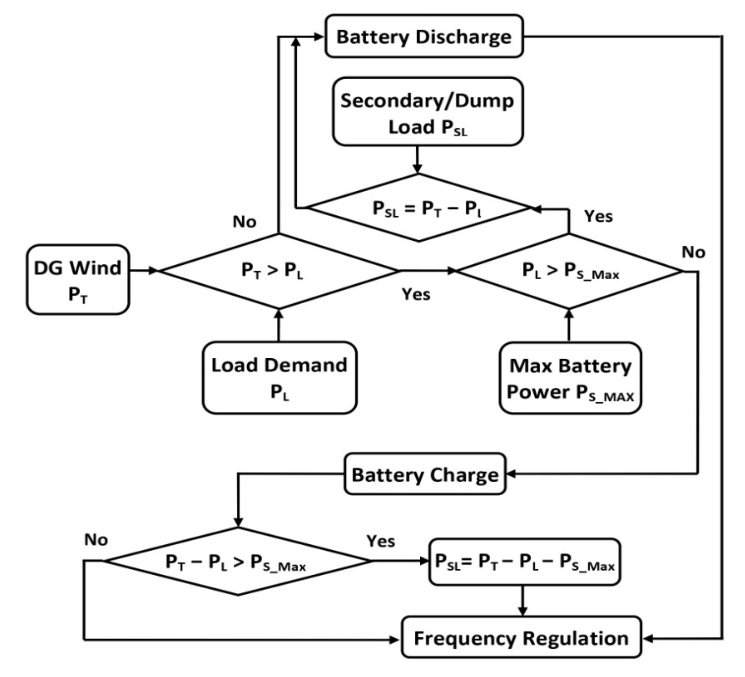
3.2. The BESS Control Strategies

The BESS follows two strategies of control mode [21,22,41].
As an inverter, the BESS supplies power to the network, Ps < 0. As a result, the BESS discharges to provide the required power to fulfill the load demand as the current passes through the network. Thereby, the velocity of the wind turbine is defined. Consequently, the power produced by the wind turbine is not enough to cover consumer load demand.
As a rectifier, the BESS consumes the surplus power from the network, Ps > 0. Hence, the BESS charges bypass the current from the network. In this situation, the velocity of the wind turbine is very high. The power produced by the wind turbine is more than the total load demand. Therefore, the surplus power is stored by the BESS and supplied in case of sudden or peak demand.

4. Control Techniques Applied to the Network

In these scenarios, a fuzzy logic controller and a PID controller are used and compared to each other to analyze the wind power flow and frequency stability in the network. Figure 7a,b shows the operational block diagram of PID controller and fuzzy logic controller, respectively.
A three-phase PLL is used to amplify the network frequency. The network voltage is supplied as an input of the PLL. To generate a frequency error, a reference frequency of 60 Hz is considered and compared to the network frequency. The obtained frequency error is integrated to generate a phase error. In the end, the phase error is implemented using the PID controller to initiate an output signal to receive the desired level of load power. According to the characteristics of the network, the proportional gain, Kp = 255, integral gain Ki = 0, and the derivative gain Kd = 55 of the PID controller with a sample time Ts = 200 μs has been tuned to maintain the dynamic stability of the frequency in the power grid [35]. For the fuzzy logic controller, the frequency error (input 1) is merged with the derivative of frequency error (input 2) and sends to the fuzzification interface where the defuzzification (output) is previously determined according to the characteristics of the PWM signal.

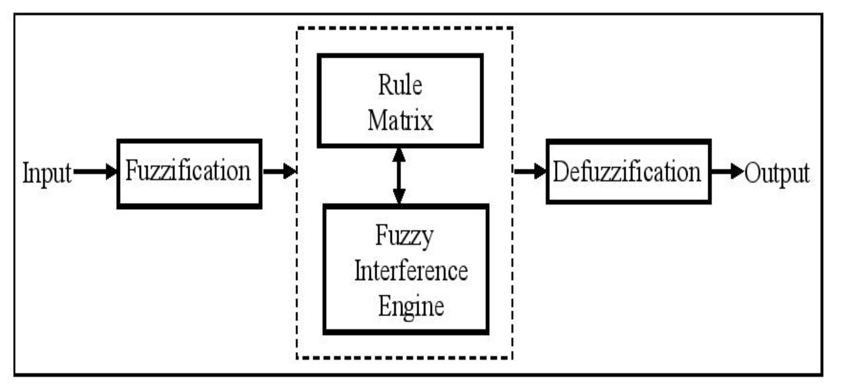
4.1. Fuzzy Logic Control Technique

Fuzzy logic is a logical algorithm that allows for the true condition to be between 0 and 1. In these situations, the fuzzy logic controller can be defined as a degree of truth. It mainly involves four operational units: (a) the fuzzification interface, (b) rule matrix interface, (c) fuzzy engine interference, and (d) defuzzification interface, as shown in Figure 8. The fuzzification interface especially associates with the input’s parameters. To decide the pre-defined Membership Function (MF), input parameters are fuzzified. The MF can be designed with different structures like sinusoidal, triangular, exponential, and trapezoidal. It is defined by selecting the position of input on the x-axis and the quantity of class variables input on the y-axis. The MF should have to keep the quantity of class variables in the range between 0 and 1. The rule matrix interface unit is used to determine the sets of fuzzy rules and the operation of the conditional functions. The rules of fuzzy logic are described as follows:
If x = A and y = B, then z = C
where both A and B are sets of conditions to be fulfilled, and C is a set of results to be analyzed. The defuzzification interface transforms the fuzzy values into crisp values. Several operational techniques of defuzzification interface can be performed (weight average, bisector mean, centroid, and max-membership) [42,43].

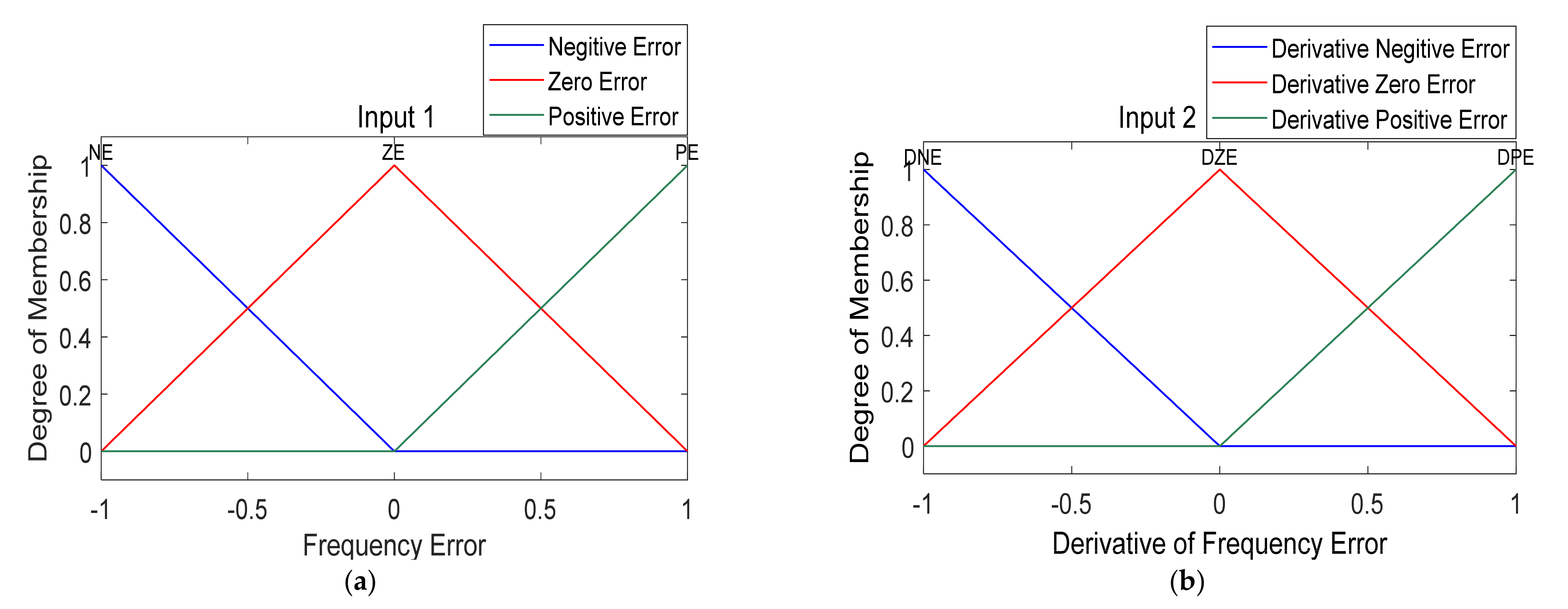
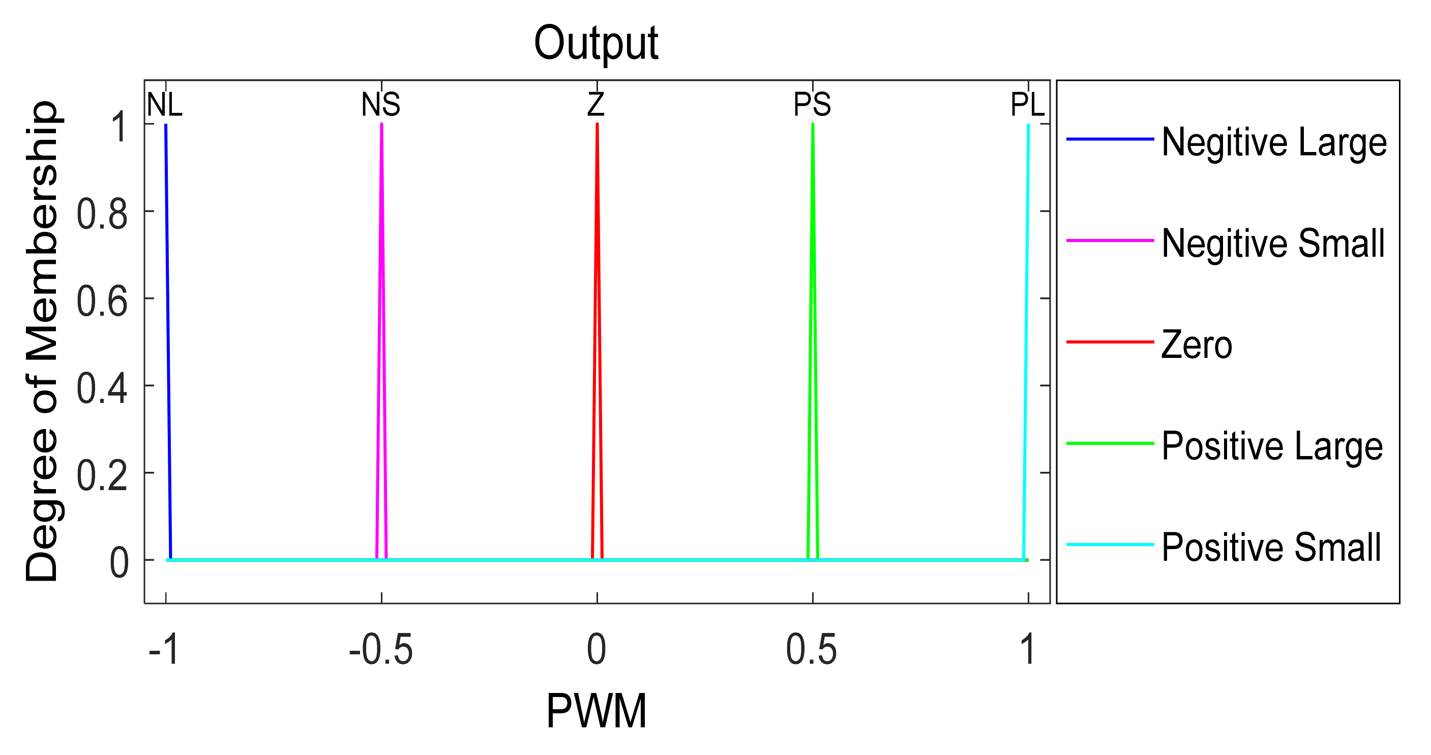
4.2. Operational Principle of MF and Their Rules

  • Stage 1: At the beginning of the operation, the input and output of the fuzzy logic controller as well as the dimensions of its variables must be determined. According to the matrix rule, the input signal must be in the ‘IF’ segment and the output signal must be in the ‘THEN’ segment.
  • Stage 2: The MF and the fuzzy sets must be defined. Then, the degree of fuzzy MF must connect with all input variables where the output signal is previously identified.
  • Stage 3: Here, the fuzzy-interference engine must be described. Then, the rules of the fuzzy logic should be converted to the control rules and regulate the controller with respect to the rules.
  • Stage 4: At the end, the defuzzification interface processes the rules and transforms the output values of fuzzy logic to the crisp values.
For this case study, the fuzzifier converts two input signals. The first signal is frequency error (∆ω) and the other one is the signal of the derivative of the frequency error which can be defined as the rate of change of the frequency error signal ∆(∆ω). As an output signal, the defuzzification decodes the PWM signal. In this fuzzy logic controller, the frequency error signal is applied as input 1. The dimension of this input variable is in the range +1 to −1 which has three MFs. The domain of MFs is split up into three linguistic areas designated by ‘Positive Error’ (0 1 1), ‘Zero Error’ (−1 0 1), and ‘Negative Error’ (−1 −1 0). The structure of the three MFs corresponds with a triangular-based MF. Figure 9a shows the MFs of the three linguistic variables.
The rate of change of the frequency error signal ∆(∆ω) is applied as input 2. The dimension of this input variable is in the range +1 to −1 which has three MFs. The domain of MFs is split up into three linguistic areas designated by ‘Positive Error’ (0 1 1), ‘Zero Error’ (−1 0 1), and ‘Negative Error’ (−1 −1 0). The structure of the three MFs corresponds with a triangular-based MF and they overlay each other. Figure 9b shows the MFs of three linguistic variables.
The output fuzzy logic consists of five MFs which are based on the PWM signal. The dimension of this output variable is in the range −1 to +1. The domain of the output MF is split up to five linguistic areas designated by ‘Positive Large’ (1 1 1), ‘Positive Small’ (0.5 0.5 0.5), ‘Zero’ (0 0 0), ‘Negative Small’ (−0.5 −0.5 −0.5), and ‘Negative Large’ (−1 −1 −1). The structure of all MFs is correspond with a triangular-shaped MF. Figure 10 shows the MFs of the three linguistic variables.
The major components of the fuzzy logic controller are the mechanism inference and the rules. Generally, the fuzzy logic rules are classified in a set of linguistic algorithms. Each rule is triggered with varying judgment to support the MF’s inputs as well as output. To operate the entire system, a set of nine IF-THEN rules are shown in Table 2. A triangular-based MF is used for each fuzzy set.
To set up the fuzzy rule-based system, the Zadeh logical ‘and’ is used, and is defined as:
µX and µY = min {µX, µY}
where, µX, µY are the input membership functions of the fuzzy sets of X and Y, respectively. The operational rule-base of the fuzzy logic controller is presented in Table 3. A centroid defuzzifier interface is used to convert the fuzzy sets into real numbers. The output ů(t) of the fuzzy logic controller is as follows:
ů t = h i µ i µ i
where, hi is the output member value of i-th rule and µi is the value of the output membership function of the i-th rule. To obtain the final required PWM duty cycle, the Equation (12) should be integrated.

5. Connection of Wind Turbine with SL and BESS to the Power Network

In this paper, the analysis of the dynamic stability of wind power flow and the behavior of frequency fluctuation using a BESS in the power network is performed. In this case study, an example is considered for a High Penetration, No Storage Wind–Diesel system (HPNSWD) [23,27,44]. This model was developed by Hydro Quebec for an isolated region to reduce the installation and maintenance cost of the power generation system. The maximum power produced by the wind turbine relies on the feasible wind resources as well as fuel cost [42]. A wind turbine asynchronous generator rated at 480 V, 275 kVA, a synchronous condenser generator rated at 480 V, 300 kVA, a BESS rated at 240 V, 390 Ah, a SL (varying between 0 to 446.25 kW), and consumer load rated up to 230 kW are used in this case study. According to the studied case, two scenarios of operation of the power network to ensure the dynamic stability of the power flow and control of the frequency fluctuation are considered [21,22].
  • Scenario 1: Power produced by a wind turbine (PT) is > overall load demand (PL). In this situation, the BESS (PS) will be charged.
  • Scenario 2: Power produced by a wind turbine (PT) is < overall load demand (PL). In this situation, the BESS (PS) will be discharged.
The two scenarios are analyzed in detail in Section 6 and related to a simulation and results.

6. Simulation and Result

To provide an adequate amount of energy to consumers, a wind speed of 10 ms−1 must be maintained in the turbine. In this case, the diesel generator is idled. The synchronous machine runs as a synchronous condenser when the mechanical power (Pm) input of the synchronous machine is fixed to zero. When the wind turbine operates at a velocity of 10 ms−1, an output power of 206 kW is obtained. Hence, the wind turbine produces 200 kW due to the losses in ASM.

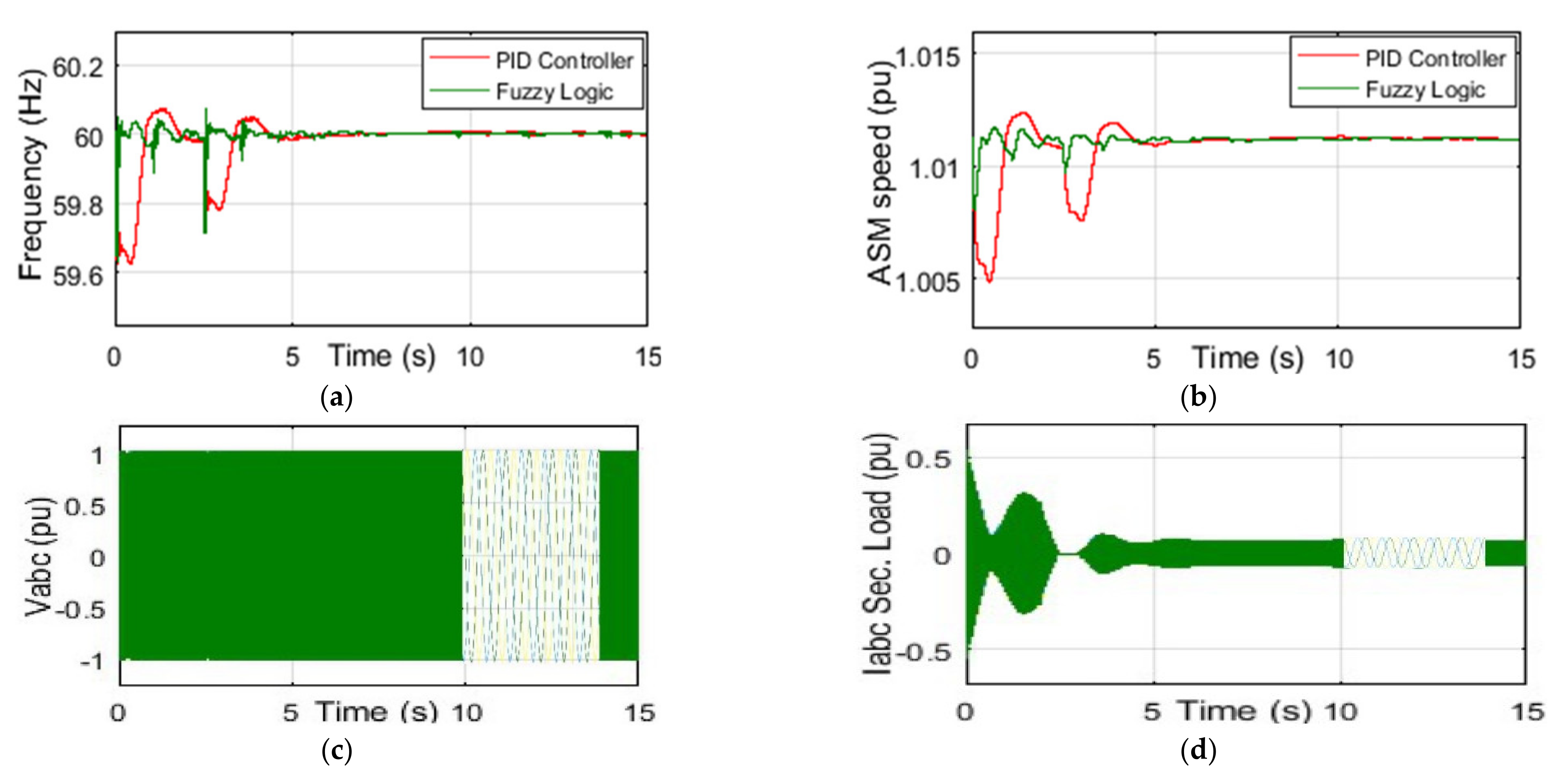
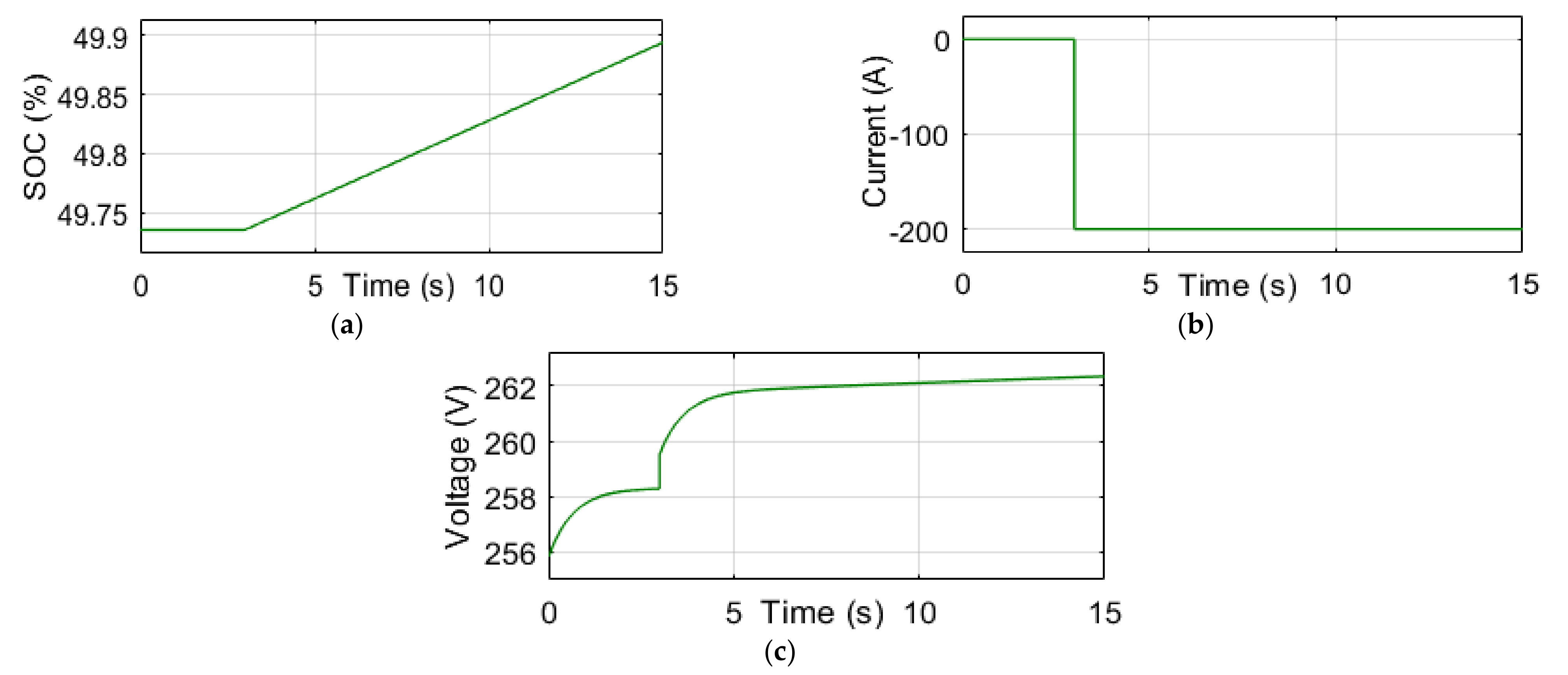
6.1. Power Produced by Wind Turbine (PT) Is > Overall Load Demand (PL). In This Situation, the BESS (PS) Will Be Charged

To analyze the dynamic stability of wind power flow, a comparison of the performance of the fuzzy logic controller over the PID controller was carried out. Figure 11a shows that the transient time of wind power is greatly reduced, and its fluctuation rate at 2.5 s is improved from 256 kW to 244 kW due to the additional load of 50 kW when using the fuzzy logic control compared to the PID controller. The synchronous condenser supplies reactive power at a rate of 15 kVA to maintain the acceptable level of voltage to the power network. Figure 11b reveals the transient time of reactive power flow produced by the synchronous condenser was also reduced using the fuzzy logic controller.
Figure 11c indicates that the main consumer load is 100 kW. An excess load of 50 kW has been connected at 2.5 s to observe the power stability and fluctuation of frequency in the network. Then, the total load of the network is 150 kW, which is less than wind power produced with respect to the load demand. Therefore, without sending the excess power to the SL, the BESS was charged at the rate of charge 30 kW in 3 s as shown in Figure 11d. Figure 11e shows the SL only absorbed 20 kW that the battery cannot store to regulate the frequency of 60 Hz.
Figure 12a shows the transient time of network frequency is significantly reduced. Additionally, the frequency fluctuation rate at 2.5 s due to the excess load of 50 kW is improved from 59.68 Hz to 59.75 Hz using the fuzzy logic controller compared to the PID controller. The velocity of the ASM is reached at 1.01 pu and runs in a generator mode. The transient time of ASM velocity is also reduced using the fuzzy logic controller shown in Figure 12b. Figure 12c shows the system voltage stays at 1 pu. For more observations, data was collected from 10 s to 14 s. The current of the SL decreased at 2.5 s due to an excess load of 50 kW. The SL also decreases at 3 s due to the BESS (rate of 30 kW) charging state, shown in Figure 12d.
Figure 13a presents the State of Charge (SOC) of the BESS at 50%. At this point, the BESS is charged from 49.7% to 49.9%. The BESS current situation is shown in Figure 13b. The BESS current was zero before 3 s, but after 3 s, the BESS received a −200 A current to charge and consumed 30 kW energy from the network. The voltage of the BESS is increased at 3 s and stays at 262 V during the simulation, as shown in Figure 13c.

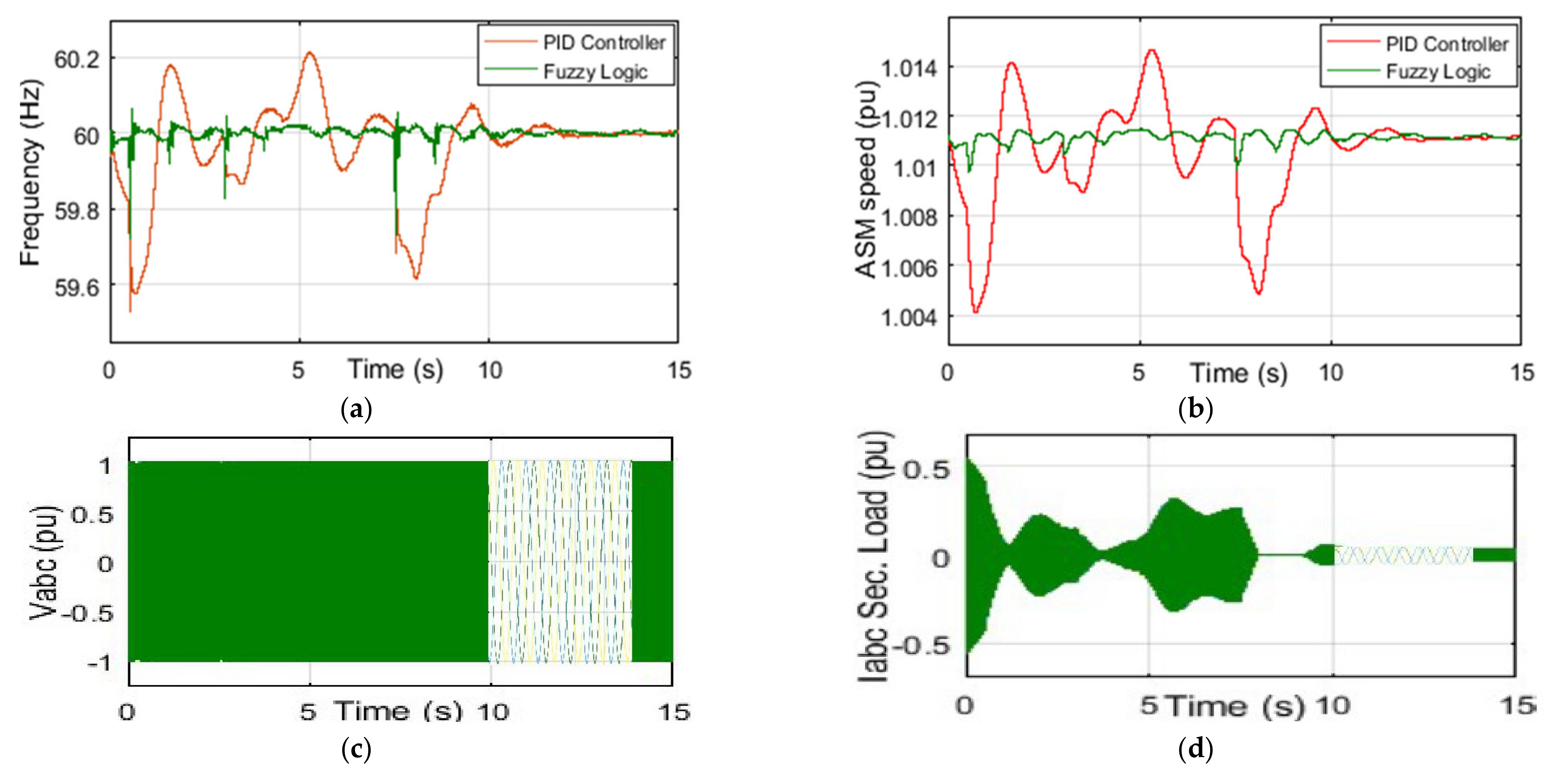
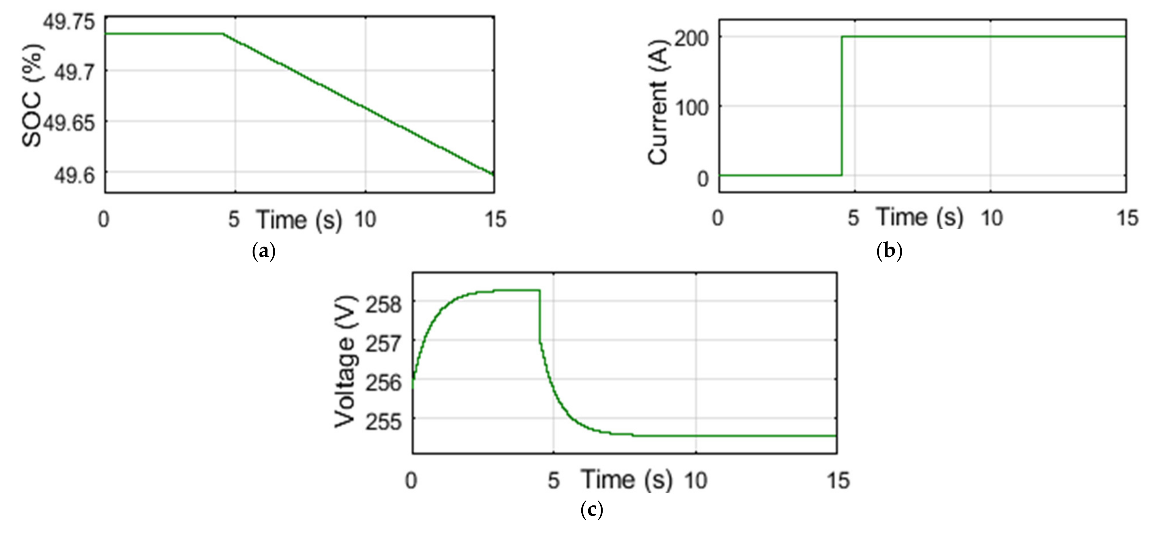
6.2. Power Produced by Wind Turbine (PT) Is < Overall Load Demand (PL). In This Situation, the BESS (PS) Will Be Discharged

To analyze the dynamic stability of wind power flow, the fuzzy logic controller is compared to the PID controller. Figure 14a shows that, by using the fuzzy logic controller compared to the PID controller, the transient time of wind power flow is significantly reduced. Additionally, the wind power fluctuation rate at 0.5 s, 3 s, and 7.5 s due to the excess load of 50 kW, 30 kW, and 45 kW are improved from 256 kW to 244 kW, 232 kW to 225 kW, and 257.5 kW to 245 kW, respectively. The synchronous condenser supplies reactive power at a rate of 15 kVA to maintain the acceptable level of voltage to the power network. Figure 14b presents the transient time of reactive power flow produced by the synchronous condenser; this was also reduced using the fuzzy logic controller.
Figure 14c shows the main consumer load is 100 kW. Excess loads of 50 kW, 30 kW, and 45 kW were connected at 0.5 s, 3 s, and 7.5 s, respectively, to analyze the wind power stability and fluctuation of the frequency in the network. Here, the total load of the network was 230 kW. This is more than the total load demand with respect to wind power generation. Therefore, the BESS has been discharged at a rated power of 50 kW in 4.5 s, as shown in Figure 14d, to maintain the high load demand in the network. Figure 14e shows the SL only absorbed 20 kW to regulate the frequency of 60 Hz.
Figure 15a shows by using the fuzzy logic controller, compared to the PID controller, the transient time of the network frequency is significantly reduced. Additionally, the frequency fluctuation rate due to the excess loads of 50 kW, 30 kW and 45 kW at 0.5 s, 3 s, and 7.5 s improved from 59.53 kW to 59.72 kW, 59.82 kW to 59.84 kW, and 59.68 kW to 59.74 kW, respectively. The velocity of the ASM was reached at 1.01 pu and ran in a generator mode. The transient time of the ASM velocity also reduced using the fuzzy logic controller; as shown in Figure 15b,c, the system voltage remained at 1 pu. For more observations, data was collected from 10 s to 14 s. Figure 15d indicates the current of the SL decreased due to the excess loads of 50 kW, 30 kW, and 45 kW at 0.5 s, 3 s, and 7.5 s, respectively. The SL also decreases at 4.5 s due to the BESS (rated power of 50 kW) discharging state.
Figure 16a represents the SOC of the BEES at 50%, where the BESS is discharged from 49.73% to 49.60%. The BESS current situation is shown in Figure 16b. The BESS current was 0 A before 4.5 s, but after 4.5 s, the BESS received 200 A to discharge itself and supply 50 kW energy to maintain the load demand in the network. The voltage of the BESS decreases at 4.5 s and remains at 254 V during the simulation, as shown in Figure 16c.

7. Discussion

From the above simulation, the result shows that, when using a fuzzy logic controller over a PID controller, the variation of wind power flow and the fluctuation of frequency reduced significantly compared to previous research. It is also observed that to maintain an acceptable level of frequency, a storage system (battery) was used to store energy without losing the surplus wind power in a SL. This energy is then consumed when there is a lack of wind power.

8. Conclusions

The technologies associated with wind-based DG, the fluctuating behavior of frequency in a wind turbine with a BESS and SL were analyzed and simulated in this paper. The wind power stability and frequency control technique were analyzed elaborately. Power-sharing methods between the BEES and SL are presented with a high penetration-based DG using a logical algorithm. Furthermore, to maintain the acceptable level of frequency, a storage system (battery) was used to store the excess of wind power and avoid loss through the SL. This stored power can be used when there is insufficient wind power generation compared to the total load demand. The response of the BESS usually depends on the technology used and its dynamics which can cause a wide variation in the power network (i.e., power flow, voltage and, frequency). Finally, the simulation shows that the fuzzy logic controller offers better performance compared to the PID controller to analyze the dynamic stability of the wind power flow and the frequency fluctuation behavior with the load variation at different times.

Author Contributions

Conceptualization, M.J.R.; Methodology, M.J.R.; Software, M.J.R.; Supervision, T.T. and M.L.D.; Writing—original draft, M.J.R.; Writing—review & editing, M.J.R., T.T., M.L.D. and N.M.-A.M. All authors have read and agreed to the published version of the manuscript.

Funding

This research work was funded by Université du Québec en Abitibi-Témiscamingue (UQAT) and the Réseau québécois sur l’énergie intelligente (RQEI).

Institutional Review Board Statement

Not applicable.

Informed Consent Statement

Not applicable.

Data Availability Statement

Data is contained within the article.

Conflicts of Interest

The authors declare no conflict of interest.

References

  1. Masson-Delmotte, V.; Zhai, P.; Pörtner, H.O.; Roberts, D.; Skea, J.; Shukla, P.R.; Pirani, A.; Moufouma-Okia, W.; Péan, C.; Pidcock, R.; et al. Global warming of 1.5 °C.An IPCC Special Report on the Impacts of Global Warming of 1.5 °C Above Pre-Industrial Levels and Related Global Greenhouse Gas Emission Pathways, in the Context of Strengthening the Global Response to the Threat of Climate Change, Sustainable Development, and Efforts to Eradicate Poverty; Intergovernmental Panel on Climate Change (IPCC): Geneva, Switzerland, 2017; ISBN 978-92-9169-151-7. [Google Scholar]
  2. Al-Sakkaf, S.; Kassas, M.; Khalid, M.; Abido, M. An Energy Management System for Residential Autonomous DC Microgrid Using Optimized Fuzzy Logic Controller Considering Economic Dispatch. Energies 2019, 12, 1457. [Google Scholar] [CrossRef] [Green Version]
  3. Hirsch, A.; Parag, Y.; Guerrero, J. Microgrids: A review of technologies, key drivers, and outstanding issues. Renew. Sustain. Energy Rev. 2018, 90, 402–411. [Google Scholar] [CrossRef]
  4. Kowalczyk, A.; Wlodarczyk, A.; Tarnawski, J. Microgrid Energy Management System. In Proceedings of the 21st International Conference on Methods and Models in Automation and Robotics (MMAR), Międzyzdroje, Poland, 29 August–1 September 2016; pp. 157–162. [Google Scholar]
  5. Zhang, H.; Davigny, A.; Colas, F.; Poste, Y.; Robyns, B. Fuzzy logic based energy management strategy for commercial buildings integrating photovoltaic and storage systems. Energy Build. 2012, 54, 196–206. [Google Scholar] [CrossRef]
  6. Chen, Y.-K.; Wu, Y.-C.; Song, C.-C.; Chen, Y.-S. Design and Implementation of Energy Management System With Fuzzy Control for DC Microgrid Systems. IEEE Trans. Power Electron. 2013, 28, 1563–1570. [Google Scholar] [CrossRef]
  7. Hosseinzadeh, M.; Salmasi, F.R. Power management of an isolated hybrid AC/DC micro-grid with fuzzy control of battery banks. Iet Renew. Power Gener. 2015, 9, 484–493. [Google Scholar] [CrossRef]
  8. García, P.; Torreglosa, J.P.; Fernández, L.; Jurado, F. Optimal energy management system for stand-alone wind turbine/photovoltaic/hydrogen/battery hybrid system with supervisory control based on fuzzy logic. Int. J. Hydrog. Energy 2013, 38, 14146–14158. [Google Scholar] [CrossRef]
  9. Kyriakarakos, G.; Dounis, A.; Arvanitis, K.; Papadakis, G. A fuzzy logic energy management system for polygeneration microgrids. Renew. Energy 2012, 41, 315–327. [Google Scholar] [CrossRef]
  10. Abadlia, I.; Bahi, T.; Bouzeria, H. Energy management strategy based on fuzzy logic for compound RES/ESS used in stand-alone application. Int. J. Hydrog. Energy 2016, 41, 16705–16717. [Google Scholar] [CrossRef]
  11. Arcos-Aviles, D.; Pascual, J.; Marroyo, L.; Sanchis, P.; Guinjoan, F. Fuzzy Logic-Based Energy Management System Design for Residential Grid-Connected Microgrids. IEEE Trans. Smart Grid 2018, 9, 530–543. [Google Scholar] [CrossRef] [Green Version]
  12. Cheng, Y.-S.; Liu, Y.-H.; Hesse, H.; Naumann, M.; Truong, C.; Jossen, A. A PSO-Optimized Fuzzy Logic Control-Based Charging Method for Individual Household Battery Storage Systems within a Community. Energies 2018, 11, 469. [Google Scholar] [CrossRef] [Green Version]
  13. Pan, I.; Das, S. Fractional Order Fuzzy Control of Hybrid Power System with Renewable Generation Using Chaotic PSO. ISA Trans. 2016, 62, 19–29. [Google Scholar] [CrossRef] [PubMed]
  14. Vairavasundaram, I.; Ravi, L.; Vairavasundaram, S.; Varadharajan, V.; Siarry, P.; Uden, L. Multi-objective optimization and energy management in renewable based AC/DC microgrid. Comput. Electr. Eng. 2018, 70, 179–198. [Google Scholar]
  15. Fossati, J.P.; Galarza, A.; Martín-Villate, A.; Echeverria, J.M.; Fontan, L. Optimal scheduling of a microgrid with a fuzzy logic controlled storage system. Int. J. Electr. Power Energy Syst. 2015, 68, 61–70. [Google Scholar] [CrossRef]
  16. Choudhury, S.; Bhowmik, P.; Rout, P. Economic load sharing in a D-STATCOM Integrated Islanded Microgrid based on Fuzzy Logic and Seeker Optimization Approach. Sustain. Cities Soc. 2018, 37, 57–69. [Google Scholar] [CrossRef]
  17. Chaiyatham, T.; Ngamroo, I. A bee colony optimization based-fuzzy logic-pid control design of electrolyzer for microgrid stabilization. Int. J. Innov. Comput. Inf. Control 2012, 8, 6049–6066. [Google Scholar]
  18. Chaiyatham, T.; Ngamroo, I.; Pothiya, S.; Vachirasricirikul, S. Design of optimal fuzzy logic-PID controller using bee colony optimization for frequency control in an isolated wind-diesel system. In Proceedings of the Transmission & Distribution Conference & Exposition, Asia and Pacific, Seoul, Korea, 26–30 October 2009; pp. 1–4. [Google Scholar]
  19. Impram, S.; Nese, S.V.; Oral, B. Challenges of renewable energy penetration on power system flexibility: A survey. Energy Strategy Rev. 2020, 31, 100539. [Google Scholar] [CrossRef]
  20. Nazari, M.; Ilić, M.; Lopes, J. Dynamic stability and control design of modern electric energy systems with large penetration of distributed generators. In Proceedings of the IREP Symposium Bulk Power System Dynamics and Control—VIII (IREP), Rio de Janeiro, Brazil, 1–6 August 2010; pp. 1–7. [Google Scholar]
  21. Rahman, J. Frequency Control in the Presence of Renewable Energy Sources in the Power Network. Master’s Thesis, École de Technologie Supérieure, Montreal, Canada, 2017. [Google Scholar]
  22. Rahman, M.J.; Tafticht, T.; Doumbia, M. Frequency Control for a High Penetration Wind-Based Energy Storage System in the Power Network. In Proceedings of the IEEE Electric Power and Energy Conference (EPEC), Kyiv, Ukraine, 9–10 November 2020; pp. 1–6. [Google Scholar]
  23. Lingamuthu, R.; Mariappan, R. Power flow control of grid connected hybrid renewable energy system using hybrid controller with pumped storage. Int. J. Hydrog. Energy 2019, 44, 3790–3802. [Google Scholar] [CrossRef]
  24. Zhao, C.; Topcu, U.; Li, N.; Low, S. Design and Stability of Load-Side Primary Frequency Control in Power Systems. IEEE Trans. Autom. Control 2014, 59, 1177–1189. [Google Scholar] [CrossRef] [Green Version]
  25. Polydoros, C.; Vita, V. Design of an Offshore Wind Farm: Connection to the Main Electrical Grid. In Proceedings of the 11th Engineering Faculty Conference (BulEF), Bourgas, Bulgaria, 3–6 June 2020; pp. 1–6. [Google Scholar]
  26. Vita, V.; Alimardan, T.; Ekonomou, L. The Impact of Distributed Generation in the Distribution Networks’ Voltage Profile and Energy Losses. In Proceedings of the IEEE European Modelling Symposium (EMS), Madrid, Spain, 6–8 October 2015; pp. 260–265. [Google Scholar]
  27. Sebastián, R.; Quesada, J. Distributed control system for frequency control in a isolated wind system. Renew. Energy 2006, 31, 285–305. [Google Scholar] [CrossRef]
  28. Zamee, M.A.; Mitra, D.; Tahhan, S.Y. Load frequency control of interconnected hydro-thermal power system using conventional pi and fuzzy logic controller. Int. J.Energy Power Eng. 2013, 2, 191. [Google Scholar] [CrossRef]
  29. Amano, H.; Oshiro, Y.; Kawakami, T.; Inoue, T. Utilization of battery energy storage system for load frequency control toward large-scale renewable energy penetration. In Proceedings of the 3rd IEEE PES Innovative Smart Grid Technologies Europe (ISGT Europe), Berlin, Germany, 14–17 October 2012; pp. 1–7. [Google Scholar]
  30. Blaabjerg, F.; Yang, Y.; Yang, D.; Wang, X. Distributed Power-Generation Systems and Protection. Proc. IEEE 2017, 105, 1311–1331. [Google Scholar] [CrossRef] [Green Version]
  31. Ahshan, R.; Saleh, S.; Al-Badi, A. Performance Analysis of a Dq Power Flow-Based Energy Storage Control System for Microgrid Applications. IEEE Access 2020, 8, 178706–178721. [Google Scholar] [CrossRef]
  32. Salama, H.S.; Aly, M.M.; Abdel-Akher, M.; Vokony, I. Frequency and voltage control of microgrid with high WECS penetration during wind gusts using superconducting magnetic energy storage. Electr. Eng. 2019, 101, 771–786. [Google Scholar] [CrossRef]
  33. Wang, Z.; Luo, D.; Li, R.; Zhang, L.; Liu, C.; Tian, X.; Li, Y.; Su, Y.; He, J. Research on the active power coordination control system for wind/photovoltaic/energy storage. In Proceedings of the IEEE Conference on Energy Internet and Energy System Integration (EI2), Beijing, China, 26–28 November 2017; pp. 1–5. [Google Scholar]
  34. Syamala, J.; Naidu, I. Load Frequency Control of Multi-AreaPower Systems Using PI, PID, and FuzzyLogic Controlling Techniques. Int. J.Innov. Res.Sci. Eng.Technol. 2014, 3, 128–1288. [Google Scholar]
  35. Nguyen, T.-T.; Martin, V.; Malmquist, A.; Silva, C. A review on technology maturity of small scale energy storage technologies. Renew. Energy Environ. Sustain. 2017, 2, 36. [Google Scholar] [CrossRef] [Green Version]
  36. Kouba, N.E.L.Y.; Menaa, M.; Hasni, M.; Boudour, M. Load Frequency Control in multi-area power system based on Fuzzy Logic-PID Controller. In Proceedings of the IEEE International Conference on Smart Energy Grid Engineering (SEGE), Oshawa, ON, Canada, 17–19 August 2015; pp. 1–6. [Google Scholar]
  37. Vidyanandan, K.V.; Senroy, N. Primary frequency regulation by deloaded wind turbines using variable droop. In IEEE Trans. Power Syst. 2013, 28, 837–846. [Google Scholar] [CrossRef]
  38. Bangash, K.N.; Farrag, M.; Osman, A. Investigation of Energy Storage Batteries in Stability Enforcement of Low Inertia Active Distribution Network. Technol. Econ. Smart Grids Sustain. Energy 2019, 4, 1–12. [Google Scholar] [CrossRef] [Green Version]
  39. Obaid, Z.A.; Cipcigan, L.; Abrahim, L.; Muhssin, M.T. Frequency control of future power systems: Reviewing and evaluating challenges and new control methods. J. Mod. Power Syst. Clean Energy 2019, 7, 9–25. [Google Scholar] [CrossRef]
  40. Sockeel, N.; Gafford, J.; Papari, B.; Mazzola, M. Virtual Inertia Emulator-Based Model Predictive Control for Grid Frequency Regulation Considering High Penetration of Inverter-Based Energy Storage System. IEEE Trans. Sustain. Energy 2020, 11, 2932–2939. [Google Scholar] [CrossRef]
  41. Magdy, G.; Mohamed, E.A.; Shabib, G.; Elbaset, A.; Mitani, Y. Microgrid dynamic security considering high penetration of renewable energy. Prot. Control Mod. Power Syst. 2018, 3, 1–11. [Google Scholar] [CrossRef]
  42. Can, S.D.L.R.D.; Leventis, G.; Phadke, A.; Gopal, A.R. Design of incentive programs for accelerating penetration of energy-efficient appliances. Energy Policy 2014, 72, 56–66. [Google Scholar]
  43. Zhao, D.; Ma, J.; Qian, M.; Zhu, L.; Yao, L.; Ding, K.; Han, H. Construction of an example system for AC/DC hybrid power grid with high proportion renewable energy. J. Eng. 2019, 16, 1117–1121. [Google Scholar] [CrossRef]
  44. Mott, L.; Saulnier, B. Commercial Wind-Diesel Project, St. Paul Island, Alaska. In Proceedings of the 14th Prime Power Diesel Inter-Utility Conference, Winnipeg, MB, Canada, 28 May–2 June 2014. [Google Scholar]
Figure 1. Operational characteristics of the wind turbine.
Energies 14 04111 g001
Figure 2. (a) Eight-bit three-phase GTO switches. (b) Operational block diagram of three-phase resistive loads.
Energies 14 04111 g002
Figure 3. (a) Block diagram of a power converter with BESS. (b) Control scheme of current-controlled inverter.
Energies 14 04111 g003
Figure 4. The control scheme of a synchronous condenser.
Energies 14 04111 g004
Figure 5. The control scheme of a synchronous condenser.
Energies 14 04111 g005
Figure 6. (a) Frequency control scheme of the WDHPS system. (b) Power-sharing strategy between the BESS and SL.
Energies 14 04111 g006
Figure 7. (a) Frequency control scheme using PID controller. (b) Frequency control scheme using fuzzy logic controller.
Energies 14 04111 g007
Figure 8. Operational diagram fuzzy logic controller.
Energies 14 04111 g008
Figure 9. (a) Membership function, Input variable 1. (b) Membership function, Input variable 2.
Energies 14 04111 g009
Figure 10. Output variables of membership function.
Energies 14 04111 g010
Figure 11. (a) The power produced by the wind turbine. (b) Reactive power supply from the synchronous condenser. (c) Power consumed by consumer load. (d) Power supplied from the BESS. (e) Power consumed by SL, when the battery is charged.
Energies 14 04111 g011
Figure 12. (a) Network frequency conditions. (b) Speed generated by ASM generator. (c) Voltage at load bus. (d) The current at SL, when the BESS is charged.
Energies 14 04111 g012
Figure 13. (a) BESS SOC condition, (b) BESS current condition and, (c) BESS voltage condition, where the BESS is charged.
Energies 14 04111 g013
Figure 14. (a) The power produced by the wind turbine. (b) Reactive power supply from the synchronous condenser. (c) Power consumed by consumer load. (d) Power supplied from BESS. (e) Power consumed by SL, when the battery is discharged.
Energies 14 04111 g014
Figure 15. (a) Network frequency conditions. (b) Speed generated by ASM generator. (c) Voltage at load bus. (d) Current at SL, where the BESS is discharged.
Energies 14 04111 g015
Figure 16. (a) The BESS SOC condition, (b) BESS current condition and, (c) BESS voltage condition, where the BESS is discharged.
Energies 14 04111 g016
Table 1. Parameters for tested WDHPS network.
SourcesSymbols/Parameters
Network480 V, 300 kVA Synchronous Generator
Turbine480 V, 275 kVA Asynchronous Generator; Wind velocity, Vnom = 10 m/s; Wind Power, Pnom = 200 kW; Pitch angle 0°
Load BusL, load (main) 100 kW, load (Extra) 50 kW, 30 kW, and 45 kW
Secondary/Dump Load Bus SL, vary 0 to 446.25 kW by step of 1.75 kW
Synchronous Condenser BusSC
Wind Turbine BusWT
Storage SystemSS, 240 V, 390 Ah, SOC 50%
Transformer150 kVA, 120 kV/480 V
Table 2. Fuzzy logic operation with “If-Then” rules.
NumberFuzzy Logic Rules
1If Frequency Error is Negative Error and Derivative of Frequency Error is Negative Derivative Error, Then PWM is Negative Large
2If Frequency Error is Negative Error and Derivative of Frequency Error is Zero Derivative Error, Then PWM is Negative Small
3If Frequency Negative Error and Derivative of Frequency Error is Positive Derivative Error, Then PWM is Zero
4If Frequency Error is Zero Error and Derivative of Frequency Error is Negative Derivative Error, Then PWM is Negative Small
5If Frequency Error is Zero Error and Derivative of Frequency Error is Zero Derivative Error, Then PWM is Zero
6If Frequency Error is Zero Error and Derivative of Frequency Error is Positive Derivative Error, Then PWM is Positive Small
7If Frequency Error is Positive Error and Derivative of Frequency Error is Negative Derivative Error, Then PWM is Zero
8If Frequency Error is Positive Error and Derivative of Frequency Error is Zero Derivative Error, Then PWM is Positive Small
9If Frequency Error is Positive Error and Derivative of Frequency Error is Positive Derivative Error, Then PWM is Positive Large
Table 3. Fuzzy rule-based operation.
Frequency Error→NEZEPS
Derivative of Frequency Error↓
DNENLNSZE
DZENSZEPS
DPEZEPSPL
Publisher’s Note: MDPI stays neutral with regard to jurisdictional claims in published maps and institutional affiliations.

