Article

Study on Asymmetric Failure and Control Measures of Lining in Deep Large Section Chamber

1
Research Center of Geotechnical and Structural Engineering, Shandong University, Jinan 250061, China
2
Stake Key Laboratory for Geomechanics and Deep Underground Engineering, China University of Mining and Technology (Beijing), Beijing 100083, China
3
Yanmei Wanfu Energy Co., Ltd., Heze 274922, China
*
Authors to whom correspondence should be addressed.
Energies 2021, 14(14), 4075; https://doi.org/10.3390/en14144075
Submission received: 9 June 2021 / Revised: 29 June 2021 / Accepted: 2 July 2021 / Published: 6 July 2021
(This article belongs to the Collection State of the Art Geo-Energy Technology in China)

Abstract

:
Lining is often used as the last line of defense in deep large section chamber. Under the asymmetric load, it is easy to damage, resulting in the overall repair of the chamber. Aiming at this problem, taking the pump house in Wanfu Coal Mine under construction in China as an engineering example, we analyzed the asymmetric failure of pump house lining caused by construction disturbance, established the lining mechanical model and quantitative evaluation indexes, such as bending moment change rate, bending moment balance rate, displacement change rate and displacement balance rate, studied the influence mechanism of asymmetrical coefficient, section size and lining thickness on the mechanical behavior of lining, and proposed the control measures of deep large section chamber with the core of “strengthening asymmetric support, reducing section size and improving lining strength”. The field monitoring shows that the asymmetric deformation of the pump house is effectively controlled, and the maximum displacement is only 7.3 mm, which ensures the long-term stability of the chamber.

1. Introduction

With the depletion of shallow coal resources and the improvement of coal mining modernization levels, the mine is developing onto a large scale, and there are more and more large section chambers [1,2]. At present, the combined support method of bolt mesh spray and high strength lining is mostly used in the deep chamber in the large section [3,4,5,6,7,8]. Especially in the core chamber with long service life, high-strength lining is regarded as the last line of defense for its advantages of high strength, high stiffness, strong sealing and favorable appearance [9,10]. When confronted with the high stress, inclined rock, secondary disturbance and other adverse factors, it is difficult to effectively control the stability of surrounding rock with a bolt mesh spray. As the last line of defense, the lining bears the load of surrounding rock; once damaged, the chamber will face a comprehensive repair. Under complex geological conditions, the loads of surrounding rock are often uneven and asymmetric, and the bearing capacity of the lining is far lower than the theoretical value. Consequently, the phenomenon of local cracking, spalling and even overall instability is very common, which poses a great threat to the safety of mine production [11,12,13].
Aiming at the deformation and failure of lining under asymmetric load, scholars have carried out a large number of studies [14,15,16,17,18,19,20,21,22,23,24]. Krzysztof Skrzypkowski [25] studied the influence of geological and mining factors on the stability of chamber excavation through roadway anchor support, and determined the key position of chamber failure. Xu Ying, Jing Shenguo et al. [26] established a mechanical model of chamber lining-anchor cable coupling support for a deep large-section pump house, studied the influence law of support parameters on the lining ultimate bearing capacity under non-uniform load, and proposed an effective reinforcement scheme. Wang Shuhong et al. [27] carried out an experimental study of the influence of the position of the cavity behind the wall on the lining failure mode, and summarized the failure modes and failure sequences of different cavity tunnels. Sun Xiaoming, Zhang guofeng, et al. [28] studied the asymmetric deformation and failure of roadway in inclined strata, obtained the key parts of the asymmetric deformation and failure of roadway in deep inclined strata, and proposed the asymmetric coupling control measures. Wang Jiong, Guo Zhibiao, et al. [29] studied the asymmetric deformation and failure characteristics of deep roadway crossings by means of numerical analysis and engineering tests, obtained the key parts of the first failure and put forward the asymmetric coupling support measures of anchor net cables. The above studies mainly focus on the asymmetric failure of lining caused by the cavity behind the lining and the attitude of the surrounding rock. The excavation of adjacent chambers will cause the construction disturbance, bringing the asymmetric load to the stable lining, which leads to deformation and failure, especially for the deep chamber with large section. At present, there are few studies on the mechanical behavior and control method of deep large section chamber lining caused by construction disturbance.
Based on this, this paper takes the permanent pump house of Wanfu Coal Mine in China as the engineering background, establishes the lining mechanical model and quantitative evaluation index based on an asymmetric coefficient, studies the influence mechanism of asymmetric coefficient, section size and lining thickness on lining mechanical behavior, proposes the control method of a deep large section chamber and guides the reinforcement of a permanent pump house in the Wanfu Coal Mine. It has an important guiding significance for engineering under similar conditions.

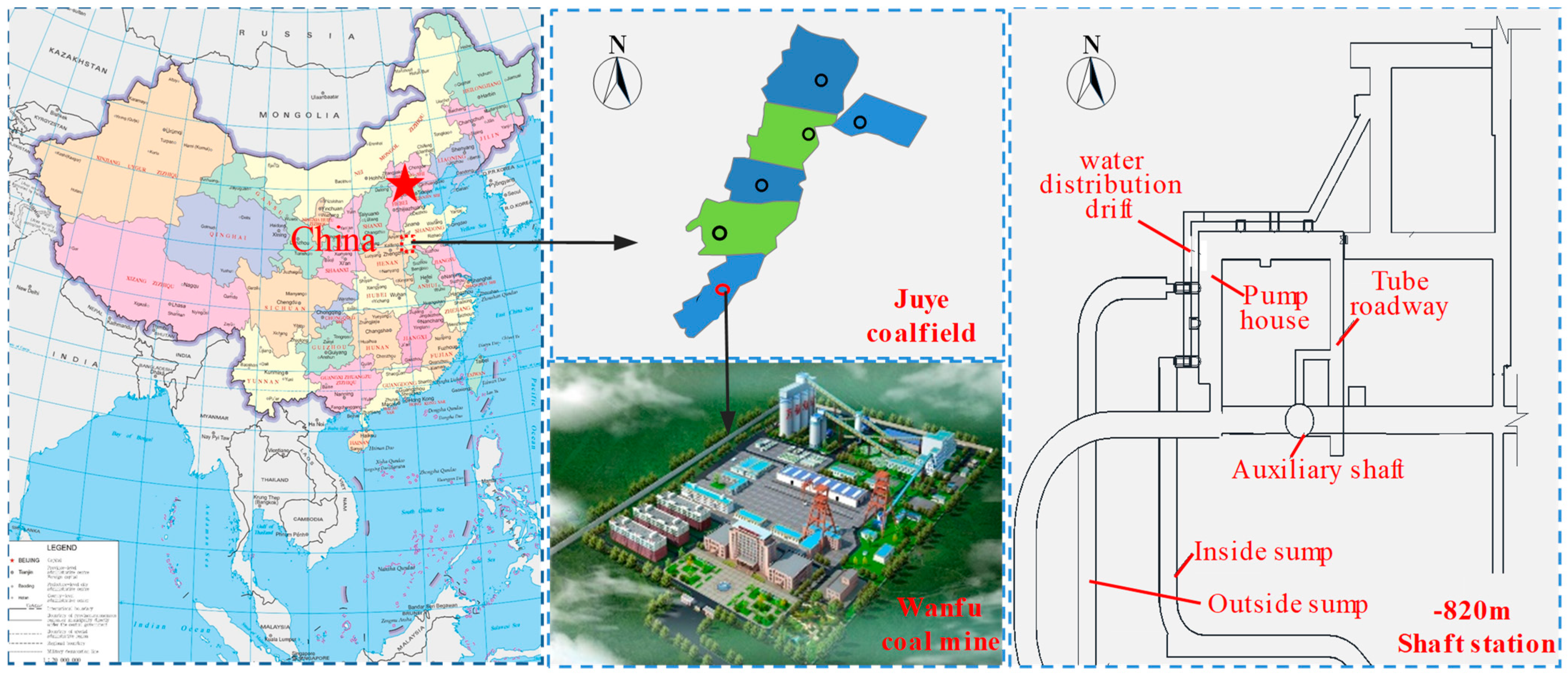
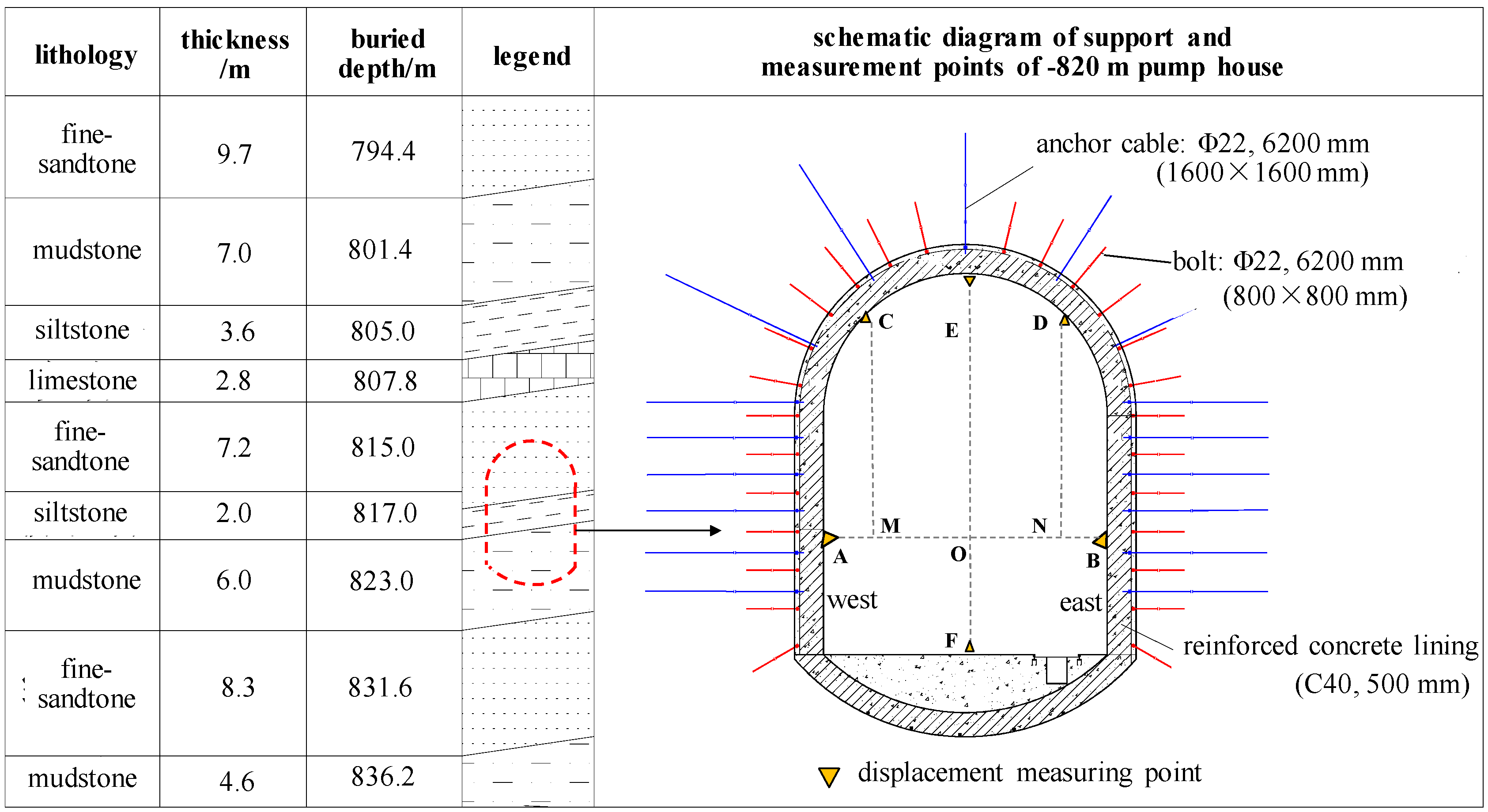
2. Engineering Background

2.1. Engineering and Geology Background

Wanfu Coal Mine is located at the southernmost point of Juye Coalfield in eastern China. It is a large-scale modern mine under construction, with a designed production capacity of 1.8 Mt/year and a design service life of 67 years. The shaft station is located at the level of −820 m, and the pump house is the largest chamber at this depth. The maximum height of the excavated section of the pump house is 10.4 m, and the maximum width is 7.2 m. The water distribution drift is located on the east side of the pump house, and is the nearest exploitation field to the pump house. The nearest horizontal distance is only 2.5 m, and the nearest vertical distance is only 1.8 m. The mine location and shaft station plan are shown in Figure 1.
The pump house is located in the inclined rock strata with the interaction of mud and sand, and the dip angle of the rock strata is 13°. From the bottom to the top, the lithology is mudstone, siltstone and fine sandstone. The maximum horizontal stress in the area is 37.1 MPa, and the vertical stress is 23.8 MPa. The pump house adopts the support form of anchor net spray + reinforced concrete lining. The parameter of anchor cable is Φ22 × 6200 mm, the inter-row spacing is 1600 × 1600 mm. Bolt parameters are Φ22 × 2500 mm, the inter-row spacing is 800 × 800 mm. Reinforced concrete lining is C40 concrete, 500 mm thick, double reinforced. The support and rock distribution of the pumping house are shown in Figure 2.

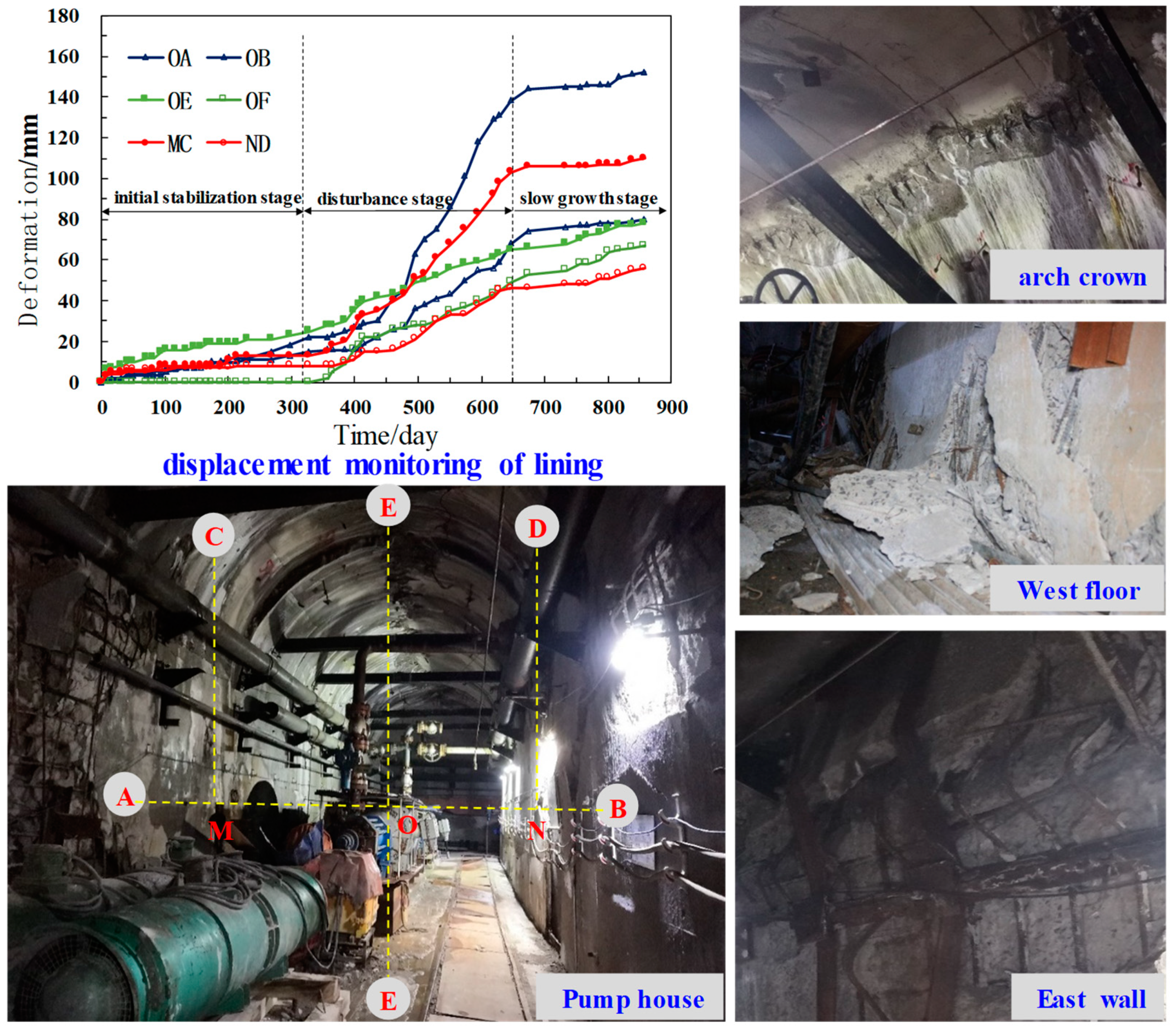
2.2. Field Failure Analysis

After lining work, long-term asymmetric deformation monitoring was carried out, including convergence of two walls (OA and OB), settlement of two arch shoulders (MC and ND) and displacement of roof and floor (OE and OF). The sensor used for convergence measurement is a mechanical convergent ruler, the accuracy is up to 0.1 mm and the monitoring frequency is once every two days by manual. The layout of measuring points is shown in Figure 2, the displacement curve and on-site damage are shown in Figure 3.
The deformation process of lining can be divided into three stages: ① the initial stable stage, as of 328 days after lining working, the pump house is stable as a whole. ② The disturbance stage, during the construction of the inside sump and water distribution drift, the deformation of the pumping house increased rapidly, and the deformation increment is as follows: west straight wall > west arch shoulder > arch top > east straight wall > arch bottom > east arch shoulder. The overall law is that the deformation on the west side is greater than that of the east side. ③ In the slower growth stage, the deformation development ratio slows down, but it is not completely stable.
In conclusion, due to the influence of water distribution drift and inside sump excavation, the original stable lining of the pump house shows asymmetric failure characteristics, and the deformation of the lining near the disturbed side is far greater than that of the other side. After the lining is damaged, the radial restraint effect on the surrounding rock is lost, and the deformation continues to develop slowly. If the reasonable reinforcement measures are not taken, it is difficult to meet the requirements.

3. Asymmetric Mechanical Model and Evaluation Index

In this section, the asymmetric mechanical model and quantitative evaluation index of lining are established to provide a basis for analyzing the deformation and stress rule of the lining under an asymmetric load.

3.1. Asymmetric Mechanical Model

Along the axial direction of the chamber, the lining per unit length is abstracted as a mechanical model, as shown in Figure 4a. In this mechanical model, the arch crown radius is r1, the arch bottom radius is r2, and the straight wall height is h. The asymmetrical coefficient of lining stress is λ. The uniform load on the left arch crown is q1, the uniform load on the left wall is q2, and the uniform load on the left bottom arch is q3. The uniform load on the right arch crown, straight wall and bottom arch is λq1, λq2 and λq3, respectively.
Based on the principle of structural mechanics [30], mechanic model of lining under asymmetric conditions is divided into positive symmetry and anti-symmetry, and the “force method” is used to solve them, respectively.
Half of the positive symmetric part is taken for analysis, as shown in Figure 4b, and it is simplified into a quadratic overstatically indetermined structure. Releasing the support constraint at point A of the vault, and replacing it with the redundant unknown forces X1 and X2 and X1 represents the horizontal support reaction (Fax) at point A, and X2 represents the constraint bending moment ( M a ) at point A, as shown in Figure 4b.
Half of the antisymmetric part is taken for analysis, as shown in Figure 4c, and it is simplified to a statically indeterminate structure. Releasing the support constraint at point A of the vault, and replacing it with the redundant unknown force X3, which represents the vertical support reaction (Fay) at point A, as shown in Figure 4c.
δ 11 X 1 + δ 12 X 2 + Δ 1 P = 0 δ 21 X 1 + δ 22 X 2 + Δ 2 P = 0 δ X 3 + Δ = 0
According to Equations (2) and (3), the basic parameters in (1) can be obtained.
δ 11 = M 1 ¯ M 2 ¯ E I d s = 9 π R 1 3 24 R 1 2 + 12 R 1 h + 4 h 2 12 E I + 4 R 2 α ( R 1 h ) 2 + R 2 3 ( 2 sin 2 α ( 1 cos α ) 2 sin α ( 1 cos 2 α ) + 6 α ) 4 E I
Similarly, δ 12 , δ 21 , δ 22 and δ can be obtained.
Δ 2 P = M 2 ¯ M P E I d s = q 1 R 1 [ R 1 2 ( 3 π 6 ) + 6 h + 3 h 2 + 6 R 2 R 1 α + 6 h α ] + q 2 h 2 ( 3 α + h ) 6 E I + R 2 2 [ q 3 R 2 ( α sin α ) + ( q 1 R 1 + q 2 h ) ( sin α cos α ) q 1 R 1 ( α sin α + cos α 1 ) ] E I
Similarly, Δ 1 P and Δ can be obtained.
For lining structure, the displacement is mainly caused by bending moment, and the displacement caused by axial force and shear force is small. Therefore, when analyzing the mechanical behavior of lining influenced by asymmetric load, only bending stress is considered. According to Equation (4), the bending moment value of any section can be obtained.
M a = M p a + X 1 M 1 ¯ + X 2 M 2 ¯ M b = M p b + X 3 M ¯ M = M a + M b
where (1)–(4), δ is the angle from the top of the structure to any section. δ i j represents the displacement of the basic structure along the Xi direction under the single action of the unit force, Δ represents the displacement of the basic structure along the X direction under the action of the load alone, EI is bending stiffness, which refers to the ability of an object to resist its bending deformation. M 1 ¯ and M 2 ¯ represent the bending moment of the unit force in any section of the basic structure, and M i represents the bending moment of the load in any section of the basic structure [31].

3.2. Analysis Scheme

Mechanical behavior of lining under asymmetric load is most significantly affected by asymmetric coefficient, section size and thickness [32]. Based on the actual parameters of the pump house in Wanfu Coal Mine, different asymmetric coefficients, section size and lining thickness are selected to analyze the influence rule on lining bending moment and displacement, corresponding to the schemes Ai, Bi and Ci, respectively, where i = 1~7. The scheme design is shown in Table 1, Table 2 and Table 3.

3.3. Evaluation Indexes

In order to quantitatively analyze the influence rules of different factors on lining bending moment and displacement, evaluation indexes such as bending moment change ratio, bending moment balance ratio, displacement change ratio and displacement balance ratio are established.
  • bending moment change ratio
    γ x y - z = | M x n y M x 1 y | | M x 1 y | × 100 %
  • bending moment balance ratio
    δ x y = 2 | M x n y l M x n y r | | M x n y l | + | M x n y r | × 100 %
  • displacement change ratio
    ε x y - z = | D x n y D x 1 y | | D x 1 y | × 100 %
  • displacement balance ratio
    φ x y = 2 | D x n y l D x n y r | ( D x n y l + D x n y r ) × 100 %
    where, M x n y —In the xn scheme, the sum of absolute values of crown bending moments on both left and right sides at y distance from the arch bottom. M x n y l —In the xn scheme, the bending moment value at y position of the left. In the xn scheme, the sum displacement of lining on both left and right sides is at y distance from the arch bottom. In the xn scheme, the displacement value of the right arch body is from the y position of the arch bottom. Where x is A~C, representing three types of schemes respectively; n is 2~7, representing 2~7 schemes respectively; y is the distance to the arch foot; l and r represent the left and right respectively.
The bending moment change ratio indicates the change of lining bending moment at a certain position. The greater the γ x y - z , the greater the bending moment is affected. The bending moment balance ratio indicates the bending moment difference between the left and the right, and the larger the δ x y , the more unbalanced the lining. The change ratio of displacement indicates the change of lining deformation at a certain position. The larger the ε x y - z , the greater the deformation is influenced. Displacement balance ratio indicates the difference between left and right deformation. The greater the δ x y , the worse the displacement balance.

4. Analysis of Asymmetric Mechanical Behavior of Lining

The section size of the −820 m pump house in Wanfu Coal Mine is 46.5 m² (R1 = 3.5 m, R2 = 4.8 m, h = 5.3 m), the surrounding rock pressure is q1 = 100 kN/m, q2 = 150 kN/m, q3 = 50 kN/m, lining thickness is 0.5 m, and C40 reinforced concrete is adopted. The elastic modulus is 32.5 GPa, and the moment of inertia per unit length lining is 5.3 × 10⁻³ m4. By substituting the specific parameters into the corresponding Equations (1)–(4), the bending moment value M of each position can be calculated. To reduce the computational workload, 42 feature points are taken along the entire lining. On this basis, the influences of asymmetric coefficient, section size of chamber and lining thickness on lining bending moment and displacement are analyzed. In order to quantitatively evaluate the influence of various factors on the lining, the 45° position on both sides of the top arch is taken.

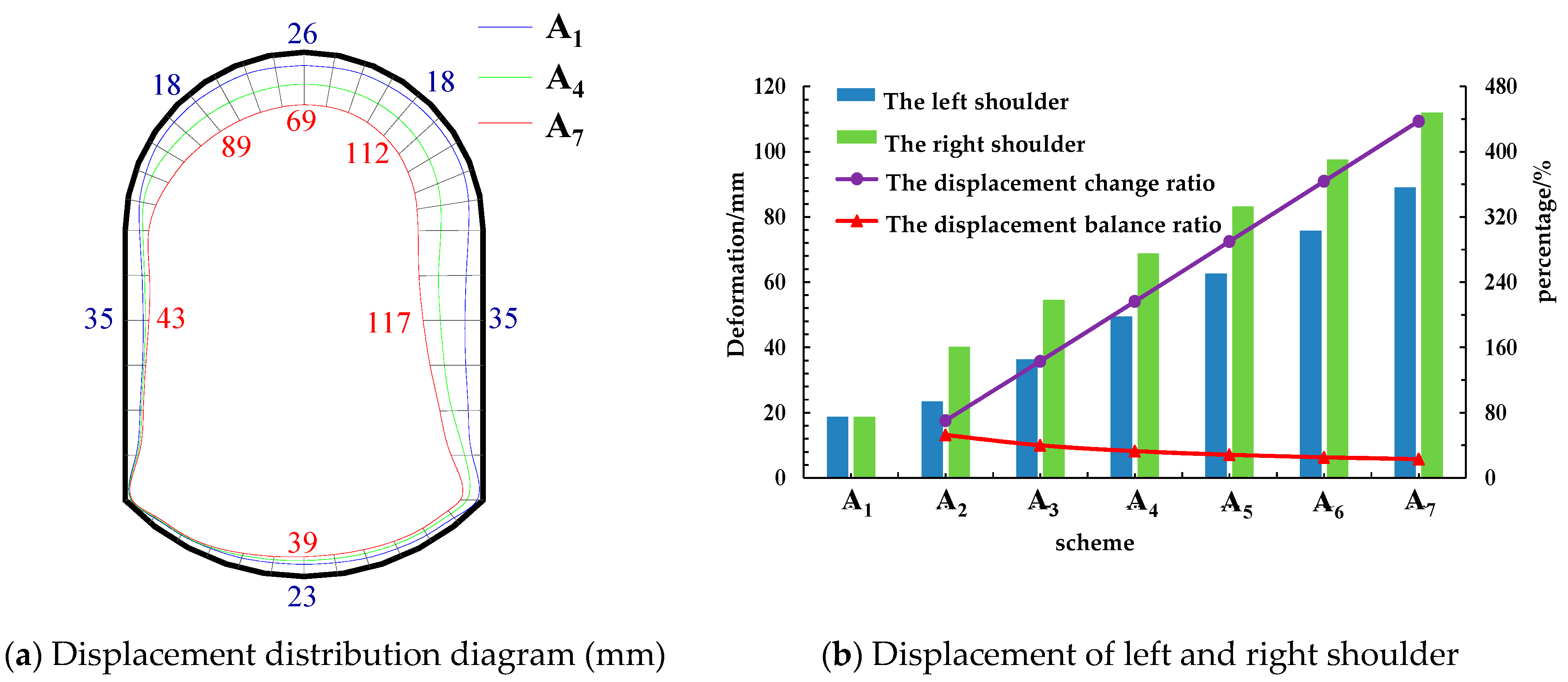
4.1. Asymmetric Coefficient

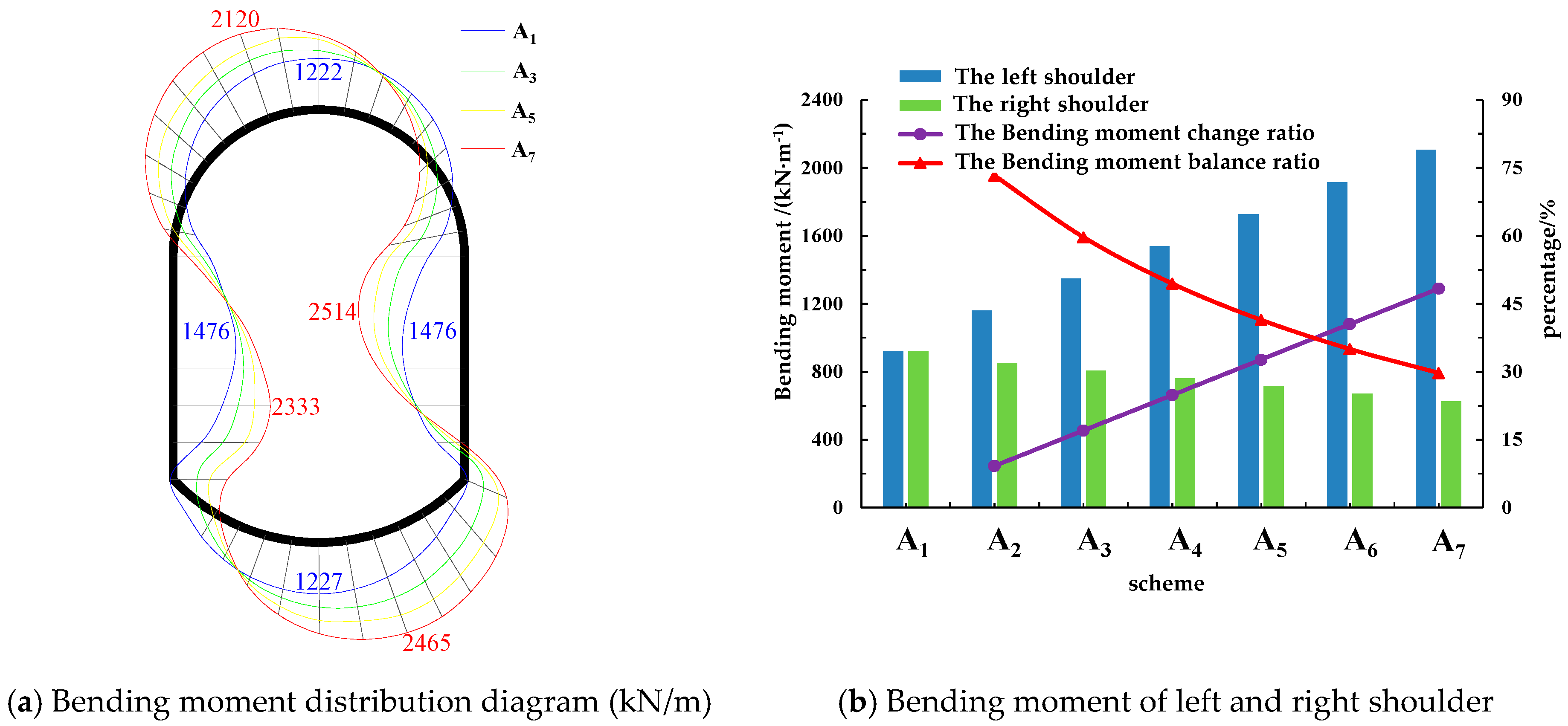
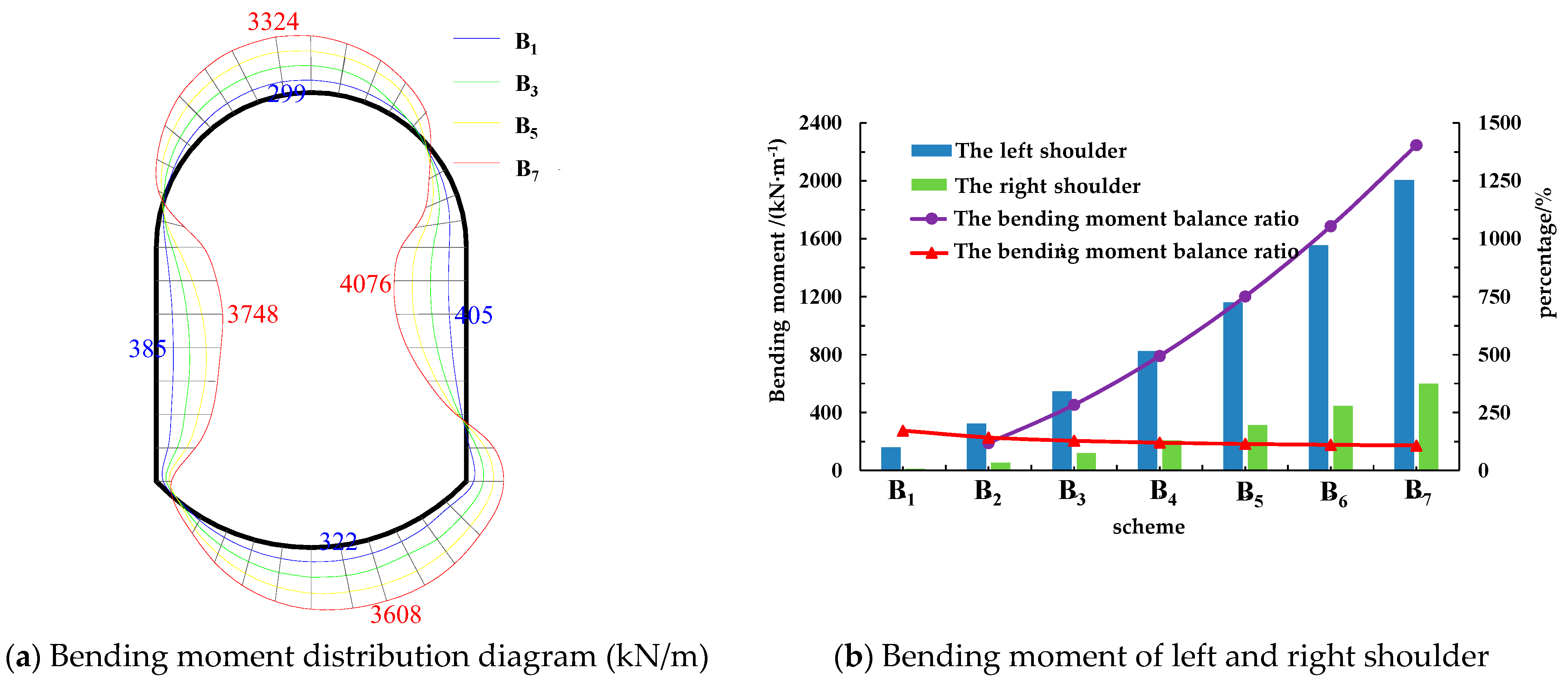
4.1.1. Bending Moment Analysis

The following result analysis can be obtained from Figure 5.
Under the action of symmetrical force, the bending moment of lining distributes symmetrically. With the increase of the asymmetry coefficient, the bending moment of the left arch crown is larger than the right arch crown, and the distribution of the bending moment of the bottom arch is opposite. The bending moment of the right straight wall is larger than the left.
Taking the left and right shoulder as an example, the bending moment of the left shoulder increases from 920 kN/m to 2104 kN/m and the bending moment of the right shoulder decreases from 920 kN/m to 625 kN/m, with the increase of the asymmetry coefficient from 1 to 1.6. The change ratio of bending moment of the shoulder is positively correlated with the asymmetric coefficient, which increases from 15% to 48%. The bending moment balance ratio is negatively correlated with the asymmetry coefficient, which decreases from 75% to 30%.

4.1.2. Displacement Analysis
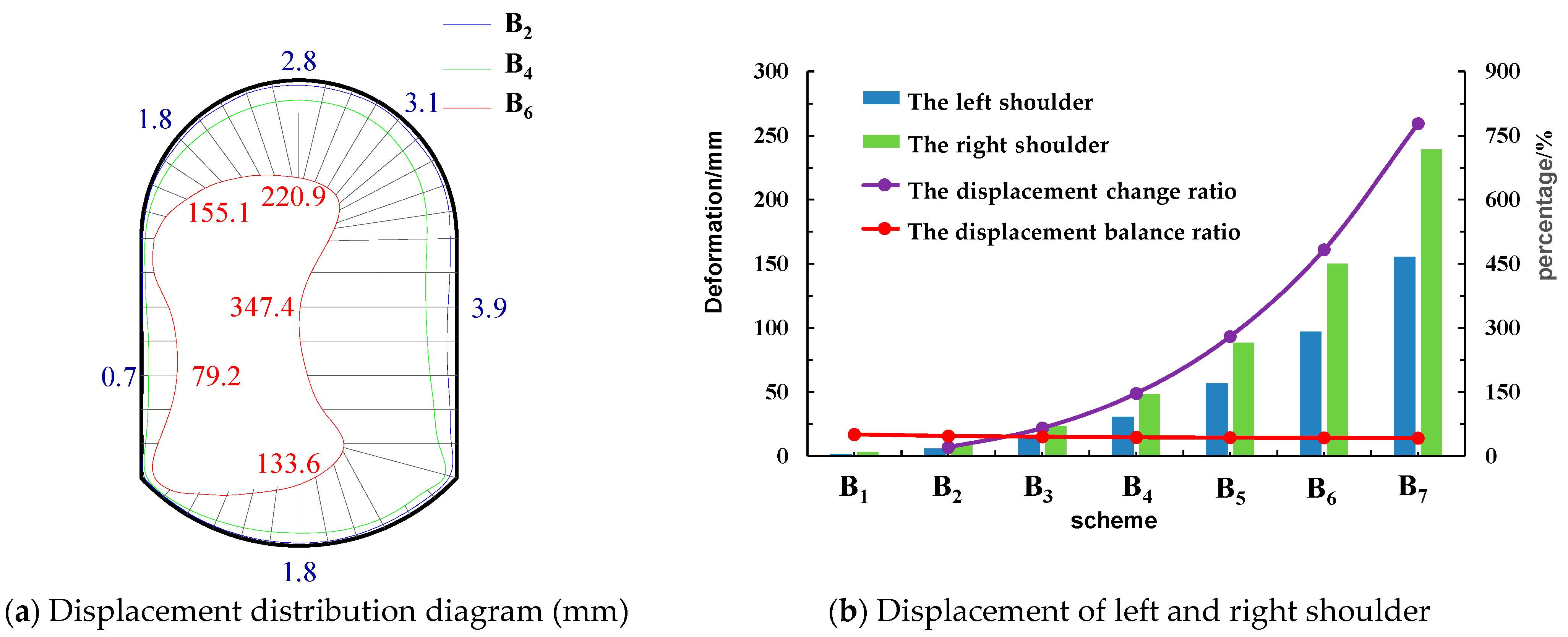
The following result analysis can be obtained from Figure 6.
Under the action of the symmetric force, the displacement is distributed symmetrically. The maximum displacement of the straight wall is 35 mm, and the maximum displacement of the top arch is 26 mm. As the asymmetry coefficient increased, the overall lining displacement increased, and the increase of the right lining displacement (the larger force side) was greater than the left.
Taking the left and right shoulder displacements as an example, the left shoulder displacements increased from 18 mm to 89 mm and the right shoulder displacements increased from 18 mm to 112 mm, with the increase of the asymmetry coefficient from 1 to 1.6. The displacement change ratio of the shoulder is positively correlated with the asymmetry coefficient, which increases from 70% to 437%. The displacement balance ratio is negatively correlated with the asymmetry coefficient and decreased from 60% to 42%.

4.2. Section Size

4.2.1. Bending Moment Analysis

The following result analysis can be obtained from Figure 7.
With the increase of the section size of the chamber, the lining bending moment increases, but the position of maximum bending moment does not change. The maximum bending moment of the arch crown is located at the left side of the arch top. The maximum bending moment of the straight wall is located at 2 h/3 to the wall foot. The maximum bending moment of the arch bottom is on the right of the arch bottom middle.
Taking the left and right shoulder as an example, with the section size increasing from 4 m to 10 m, the bending moment of the left shoulder increases from 161 kN/m to 2006 kN/m, and the bending moment of the right shoulder increases from 12 kN/m to 298 kN/m. The bending moment change ratio increases from 118% to 1403% with the increase of section size. The bending moment balance ratio is negatively related with the section size, which decreases from 142% to 108%.

4.2.2. Displacement Analysis

The following result analysis can be obtained from Figure 8.
With the increase in the section size, the displacement of the lining increases rapidly, and the displacement value of the right side increases more obviously than that left, but the maximum displacement position remains unchanged.
Taking the displacement of the left and right shoulder as an example, with the increase of the section width from 4 m to 10 m, the displacement of the left shoulder increases from 1.8 mm to 155.1 mm, and that of the right shoulder increases from 3.1 mm to 220.9 mm. The displacement change ratio increases from 12% to 810%, and the displacement balance ratio decreases from 51% to 42%.

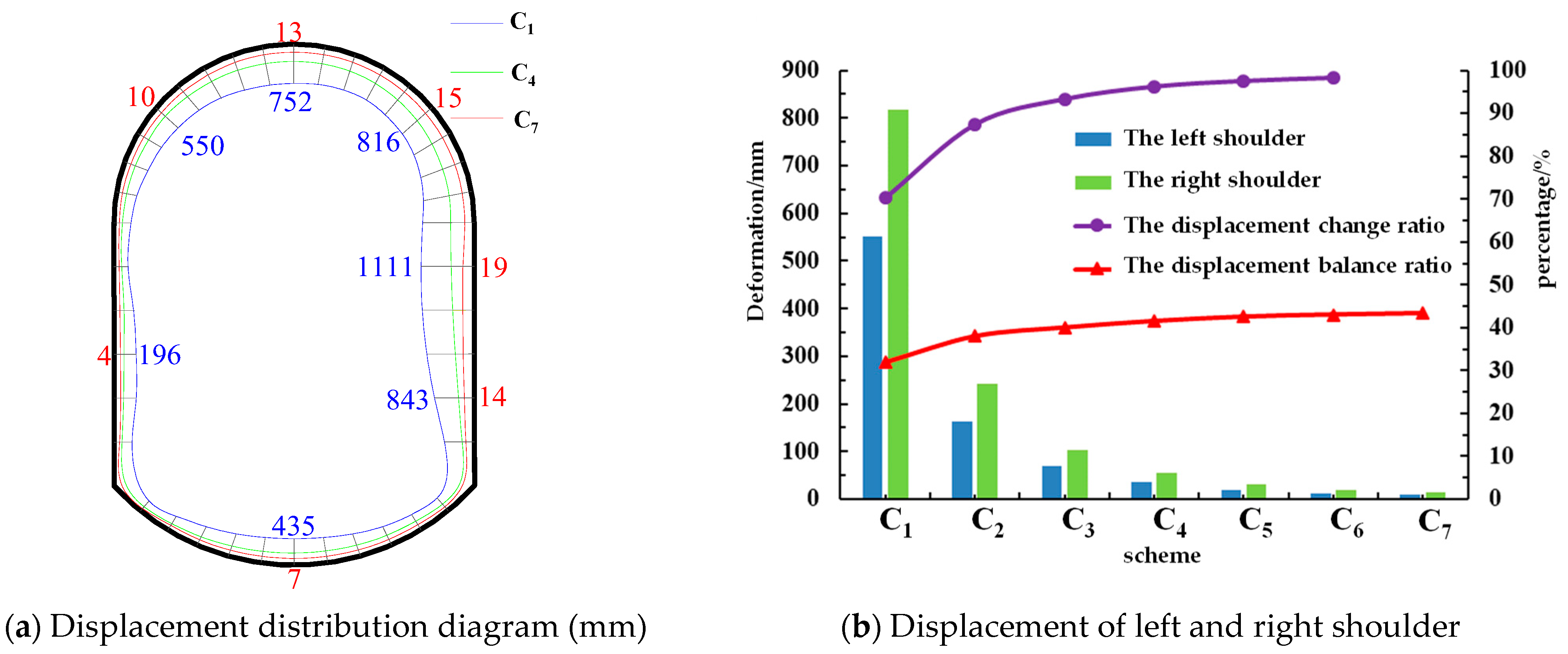
4.3. Lining Thickness

The following result analysis can be obtained from Figure 9.
With the increase of the lining thickness, the overall displacement decreased, and the displacement of the right side (the side with larger force) decreases more significantly than that of the left, and the maximum displacement position does not change.
Taking the displacement of left and right arches as an example, with the increase of arch thickness from 0.2 m to 0.8 m, the left arch shoulder displacement decreases from 550 mm to 10 mm, and the right arch shoulder displacement decreases from 816 mm to 15 mm. The displacement change ratio increases from 70% to 98%, and the displacement balance ratio increases from 39% to 42%.
When the lining thickness exceeds 0.5 m, both displacement change ratio and displacement balance ratio have little change with the continuous increase of lining thickness.

4.4. Summary and Engineering Recommendations

Under the action of asymmetric load, the bending moment and displacement of the lining show an obvious asymmetry. The larger the asymmetry coefficient is, the more significant the increase of the bending moment and displacement is, and the more serious the failure is. Therefore, for the lining chamber subjected to secondary disturbance, the asymmetric design of bolt mesh spray should be carried out, the support strength of the disturbed side should be strengthened, and the strength of the surrounding rock should be restored through grouting and other measures to reduce the asymmetric load of the lining.
The larger the section size is, the more severely the lining is affected by the asymmetric load, the change rate of bending moment and displacement of the lining increases rapidly, and the symmetry decreases continuously. Therefore, for the lining under asymmetric load, measures such as optimizing equipment selection should be taken to reduce the chamber section size to minimize the size effect.
Increasing the lining thickness can improve the ability of lining to resist asymmetric load, but when the lining thickness exceeds a certain value, the effect of increasing the lining thickness is no longer obvious. Therefore, the section size and the load size of the chamber should be considered comprehensively, and the lining thickness should be reasonably selected by using the evaluation index.

5. Control Measures and Application Effect

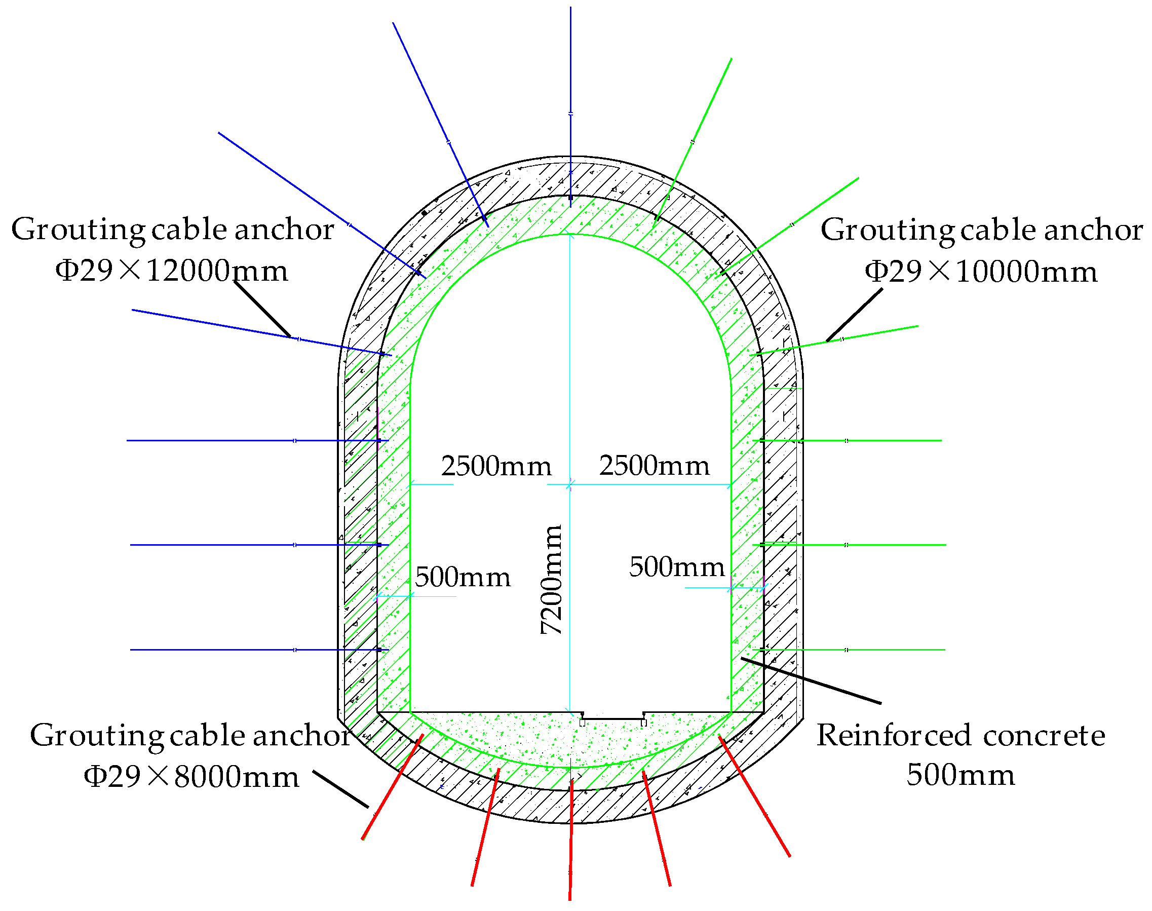
5.1. Control Measures

Under the condition of asymmetric load, the core of stability control of the deep large section chamber lining is “strengthening asymmetric support, reducing the section size and improving the lining strength”. In view of the asymmetric failure of the permanent pump house in Wanfu Coal Mine, the control method design is shown in Figure 10.
After optimization, the net section width of the pump house is 5000 mm and the height is 7200 mm, which avoids the expansion of the lining and reduces the surrounding rock disturbance.
The west straight wall and west arch shoulder of the pumping house adopt the Φ29 × 12,000 mm grouting anchor cable, and the other side adopts the Φ29 × 10,000 mm grouting anchor cable. The bottom arch adopts the Φ29 × 8000 mm grouting anchor cables. The diameter of the anchor hole is 38 mm, and two MSZ2870 resin cartridges are used. The cartridges can be cured after being stirred evenly for 5 min. After the end of grouting anchor cable is anchored, 150 kN preload is applied first, and then grouting is carried out one by one to reinforce the broken surrounding rock.
On the outside of the existing section, double-layer reinforcement is bound on the whole section, with the diameter of transverse reinforcement of 28 mm and longitudinal reinforcement of 32 mm. C40 concrete is used for pouring, and the lining thickness is 500 mm.

5.2. Application Effect

After the reinforcement following the above scheme, a deformation monitoring section is set, and the position of measuring point is the same as before. Figure 11 shows the displacement change curve of the pumping house within 90 days of reinforcement. It can be obtained that, after the reinforcement of the pumping house chamber, no obvious asymmetrical deformation continues to occur, and the maximum deformation is 7.3 mm, indicating a significant control effect.
For the permanent pump house, continuous deformation is not allowed during the reinforcement phase, and the rigid lining support is adopted to effectively avoid the continuous deformation of the pump house, which meets the support requirements. Figure 12 is the effect drawing of the pump house after reinforcement.

6. Conclusions

(1)
Aiming at the asymmetric failure of lining in Wanfu Coal Mine pump house due to the secondary disturbance, the asymmetric mechanical model of the lining and the quantitative evaluation indexes such as the change rate of bending moment, the balance rate of bending moment, the change rate of displacement and the balance rate of displacement are established, and the influence laws of the asymmetric coefficient, the section size and the thickness on the bending moment and displacement of the lining are studied.
(2)
Under the action of asymmetric load, the bending moment and displacement of lining shows an obvious asymmetry. The larger the asymmetry coefficient is, the more significant the increase of bending moment and displacement will be. The larger the section size is, the more obvious the influence of the asymmetric load is. Increasing the lining thickness is beneficial to improve the lining resistance to the asymmetric load, when the lining thickness exceeds a certain value, the effect of increasing the lining thickness is no longer obvious.
(3)
The control measures with the core of “strengthening asymmetric support, reducing section size, improving lining strength” is proposed. The field application shows that the method can effectively restrain the asymmetric deformation of the surrounding rock, and the maximum deformation is only 7.3 mm, which ensures the long-term stability of the chamber. It has an important guiding significance for engineering under similar conditions.

Author Contributions

All the authors contributed to this paper. Conceptualization, Y.H. and B.J.; methodology, H.W.; investigation, Y.H.; resources, J.Z.; data curation, X.G., Y.M.; writing—original draft preparation, Y.H., Y.M. All authors have read and agreed to the published version of the manuscript.

Funding

This work was supported by the National Natural Science Foundation of China (Grant Nos. 52074164 and 42077267); the Natural Science Foundation of Shandong Province, China (Grant Nos. 2019SDZY04 and ZR2020JQ23); the Project of Shandong Province Higher Educational Youth Innovation Science and Technology Program, China (Grant No. 2019KJG013).

Institutional Review Board Statement

Not applicable.

Informed Consent Statement

Not applicable.

Data Availability Statement

The data supporting the findings can be found in the figures, tables and manuscript.

Acknowledgments

This work is supported by Wanfu Energy Co. Ltd. and Yankuang Group Limited, which are gratefully acknowledged.

Conflicts of Interest

The authors declare no conflict of interest.

References

  1. He, M.C.; Wang, Q.; Wu, Q.Y. Innovation and future of mining rock mechanics. J. Rock Mech. Geo Eng. 2021, 13, 1–21. [Google Scholar] [CrossRef]
  2. Xie, H.P. Research review of the state key research development program of China: Deep rock mechanics and mining theory. J. China Coal Soc. 2019, 44, 1283–1305. [Google Scholar]
  3. Wang, Q.; Gao, H.K.; Jiang, B.; Li, S.C.; He, M.C.; Qin, Q. In-situ test and bolt-grouting design evaluation method of underground engineering based on digital drilling. Int. J. Rock Mech Min. Sci. 2021, 138, 104575. [Google Scholar] [CrossRef]
  4. Wang, L.G.; Lu, Y.L.; Huang, Y.G.L.; Sun, H.Y. Deep-shallow coupled bolt-grouting support technology for soft rock roadway in deep mine. J. China Univ. Min. Technol. 2016, 45, 11–18. [Google Scholar]
  5. Li, S.C.; Shao, X.; Jiang, B.; Wang, Q.; Wang, F.Q.; Ren, Y.X.; Wang, D.C.; Ding, L.G. Study of the mechanical characteristics and influencing factors of concrete arch confined by square steel set in deep roadways. J. China Univ. Min. Technol. 2015, 44, 400–408. [Google Scholar]
  6. Sun, H.B.; Li, S.C.; Wang, Q.; Zhou, L.S.; Jiang, B.; Zhang, X.; Xu, S.; Zhang, H.J. Research and Application of Fabricaed Confined Concrete Construction System for Large Cross Section. Tunn. Undergr. Space Technol. 2018, 31, 320–327. [Google Scholar]
  7. Wang, Q.; Xin, Z.X.; Jiang, B.; Sun, H.B.; Xiao, Y.C.; Bian, W.H.; Li, L.N. Comparative experimental study on mechanical mechanism of combined arches in large section tunnels. Tunn. Undergr. Space Technol. 2020, 99, 103386. [Google Scholar] [CrossRef]
  8. Guo, J.; Feng, G.R.; Wang, P.F.; Qi, T.Y.; Zhang, X.R.; Yan, Y.G. Roof Strata Behavior and Support Resistance Determination for Ultra-Thick Longwall Top Coal Caving Panel: A Case Study of the Tashan Coal Mine. Energies 2018, 11, 1041. [Google Scholar] [CrossRef] [Green Version]
  9. Wang, Q.; Xu, S.; Jiang, B.; Li, S.C.; Xiao, Y.C.; Xin, Z.X.; Liu, B.H. Research progress of confined concrete support theory and technology for underground engineering. J. China Coal Soc. 2020, 45, 2760–2776. [Google Scholar]
  10. Xu, Y.; Bo, J.B.; Wu, Z.R.; Feng, J.S. Instability Mechanism and Reinforcement Technology of Brickwork Roadway. J. Min. Saf. Eng. 2012, 29, 790–796. [Google Scholar]
  11. Huang, Y.B.; WANG, Q.; Gao, H.K.; Jiang, Z.H.; Li, S.; Chen, K. Failure mechanism and construction process optimization of deep soft rock chamber group. J. China Univ. Min. Technol. 2021, 50, 69–78. [Google Scholar]
  12. Sun, K.G.; Li, S.C.; Zhang, Q.S.; Li, S.C.; Li, J.L.; Liu, B. Study on monitoring and simulation of super-long mountain tunnel lining. Chin. J. Rock Mech. Eng. 2007, 26, 4465–4470. [Google Scholar]
  13. Wang, Q.; Jiang, Z.H.; Jiang, B.; Gao, H.K.; Huang, Y.B.; Zhang, P. Research on an automatic roadway formation method in deep mining areas by roof cutting with high-strength bolt-grouting. Int. J. Rock Mech. Min. Sci. 2020, 128, 104264. [Google Scholar] [CrossRef]
  14. Wang, Q.; He, M.C.; Jiang, B.; Li, S.C.; Jiang, Z.H.; Wang, Y.J.; Xu, S. Experimental research and application of automatically formed roadway without advance tunneling. Tunn. Undergr. Space Technol. 2021, 114, 103999. [Google Scholar] [CrossRef]
  15. Ghosh, G.K.; Sivakumar, C. Application of underground microseismic monitoring for ground failure and secure longwall coal mining operation: A case study in an Indian mine. J. Appl. Geophys. 2018, 150, 21–39. [Google Scholar] [CrossRef]
  16. Saeedi, G.; Shahriar, K.; Rezai, B.; Karpuz, C. Numerical modelling of out-of-seam dilution in longwall retreat mining. Int. J. Rock Mech. Min. Sci. 2010, 47, 533–543. [Google Scholar] [CrossRef]
  17. Rezaei, M.; Hossaini, M.F.; Majdi, A. Development of a time-dependent energy model to calculate the mining-induced stress over gates and pillars. J. Rock Mech. Geotech. Eng. 2015, 7, 306–317. [Google Scholar] [CrossRef]
  18. Zhai, X.X.; Huang, G.S.; Chen, C.Y.; Li, R.B. Combined Supporting Technology with Bolt-Grouting and Floor Pressure-Relief for Deep Chamber: An Underground Coal Mine Case Study. Energies 2018, 11, 67. [Google Scholar] [CrossRef] [Green Version]
  19. Waldemar, K.; Krzysztof, S.; Łukasz, H. Metody badania obudowy kotwowej w Katedrze Górnictwa Podziemnego AGH. Cuprum 2015, 3, 49–60. [Google Scholar]
  20. Wang, Q.; Qin, Q.; Jiang, B.; Xu, S.; Zeng, Z.N.; Luan, Y.C.; Liu, B.H.; Zhang, H.J. Mechanized construction of fabricated arches for large-diameter tunnels. Automat. Constr. 2021, 124, 103583. [Google Scholar] [CrossRef]
  21. Chang, B.L.; Li, J.B.; Xu, Y. Instability mechanism and control technology of Surrounding rock of brickwork roadway. Saf. Coal Min. 2015, 46, 100–103. [Google Scholar]
  22. Zhao, M.Z.; Meng, W.F.; Lu, D.H.; Huang, C.F. Damage of upper arch walling support roadway with lower working face mined. J. Min. Saf. Eng. 2011, 36, 23–27. [Google Scholar]
  23. Wang, Q.; He, M.C.; Xu, S. Mechanical properties and engineering application of bolt made of new constant resistance energy absorbing materials. J. China Coal Soc. 2021. [Google Scholar] [CrossRef]
  24. Liu, Q.S.; Shi, K.; Kang, Y.S.; Huang, X. Monitoring analysis of secondary lining structure of central pump house in deep coal mine. Chin. J. Rock Mech. Eng. 2011, 30, 1596–1603. [Google Scholar]
  25. Skrzypkowski, K. Case Studies of Rock Bolt Support Loads and Rock Mass Monitoring for the Room and Pillar Method in the Legnica-Gogów Copper District in Poland. Energies 2020, 13, 2998. [Google Scholar] [CrossRef]
  26. Jing, S.G.; Su, Z.L.; Wang, X.K. Research and application on the coupling mechanism of cable and masonry for chamber with large-section. J. Min. Saf. Eng. 2018, 35, 1158–1163. [Google Scholar]
  27. Wang, S.H.; Wang, P.Y.; Liu, Y.; Zhu, B.Q. Experimental Study on failure mode of tunnel model containing cavity in different locations. J. Northeast. Univ. 2020, 41, 863–869. [Google Scholar]
  28. Sun, X.M.; Zhang, G.F.; Cai, F.; Yu, S.B. Asymmetric deformation mechanism within inclined rock strata induced by excavation in deep roadway and its con-trolling countermeasures. J. Rock Mech. Eng. 2009, 28, 1137–1143. [Google Scholar]
  29. Wang, J.; Guo, Z.B.; Cai, F.; Hao, Y.X.; Liu, X. Study on the asymmetric deformation mechanism and control countermeasures of deep layers roadway. J. Min. Saf. Eng. 2014, 31, 28–31. [Google Scholar]
  30. Long, Y.Q.; Bao, S.H. Course of Structural Mechanics; Higher Education Press: Beijing, China, 2001; pp. 79–91. [Google Scholar]
  31. Fan, Z.; Shi, S.; Li, Z.B.; Wang, Q.Q.; Zhao, C.J.; Kou, L.; Shi, J.W. Research on large diameter concrete filled tubular column and H-section beam connection. J. Build. Struct. 2016, 37, 1–12. [Google Scholar]
  32. Zhu, W.S.; He, M.C. Stability and Dynamic Construction Mechanics of Surrounding Rock under Complex Condition; Beijing Science Press: Beijing, China, 1995; pp. 155–182. [Google Scholar]
Figure 1. Mine location and −820 m shaft station plan.
Energies 14 04075 g001
Figure 2. The support and rock distribution of the pumping house.
Energies 14 04075 g002
Figure 3. The displacement curve and on-site damage.
Energies 14 04075 g003
Figure 4. Mechanical calculation model of lining under asymmetric force.
Energies 14 04075 g004
Figure 5. Bending moment analysis with different asymmetric coefficients. (a) Bending moment distribution diagram (b) Bending moment of left and right shoulder.
Energies 14 04075 g005
Figure 6. Displacement analysis of different asymmetric coefficients. (a) Displacement distribution diagram (b) Displacement of left and right shoulder.
Energies 14 04075 g006
Figure 7. Bending moment analysis of different section sizes. (a) Bending moment distribution diagram (b) Bending moment of left and right shoulder.
Energies 14 04075 g007
Figure 8. Displacement analysis of different section sizes. (a) Displacement distribution diagram (b) Displacement of left and right shoulder.
Energies 14 04075 g008
Figure 9. Displacement analysis of different lining thickness. (a) Displacement distribution diagram (b) Displacement of left and right shoulder.
Energies 14 04075 g009
Figure 10. Schematic diagram of reinforcement scheme.
Energies 14 04075 g010
Figure 11. Displacement monitoring of pump house after reinforcement.
Energies 14 04075 g011
Figure 12. Field effect of pump house after reinforcement.
Energies 14 04075 g012
Table 1. Analysis scheme of different asymmetric coefficients.
Scheme No./AiAsymmetric Coefficient/λInvariant
A11q1, q2, q3
h, r1, r2
d
A21.1
A31.2
A41.3
A51.4
A61.5
A71.6
Table 2. Analysis scheme of different chamber section size.
Scheme No./BiSection SizeInvariant
Arch Crown Radius/r1Wall Height/hArch Bottom Radius/r2
B14.02.30.2q1, q2, q3
d
λ
B25.03.30.3
B36.04.30.4
B47.05.30.5
B58.06.30.6
B69.07.30.7
B710.08.30.8
Table 3. Analysis scheme of different lining thickness.
Scheme No./CiThickness/mInvariant
C10.2q1, q2, q3
h, r1, r2
λ
C20.3
C30.4
C40.5
C50.6
C60.7
C70.8
Publisher’s Note: MDPI stays neutral with regard to jurisdictional claims in published maps and institutional affiliations.

