
Efficient and Robust Image Communication Techniques for 5G Applications in Smart Cities


Abstract
:1. Introduction
2. Related Work
Our Contribution
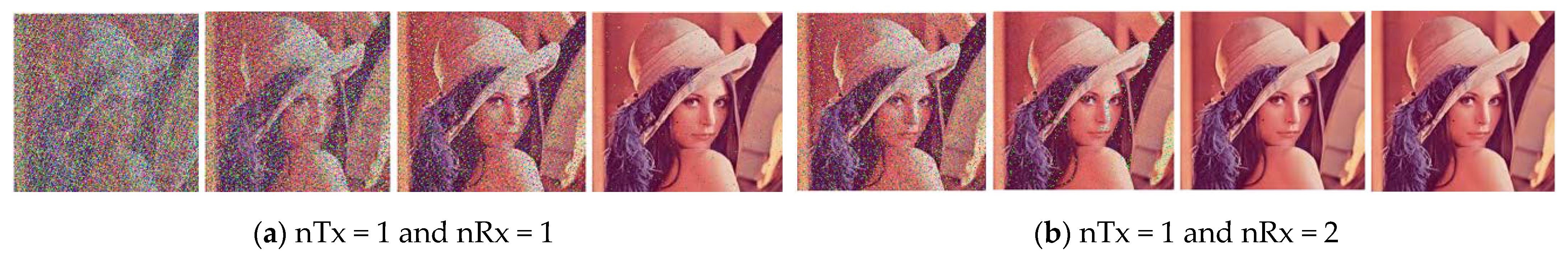
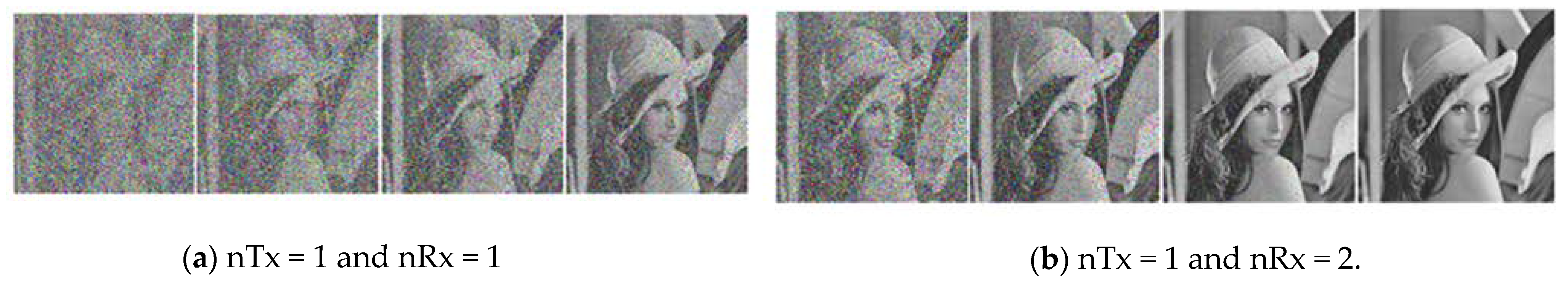
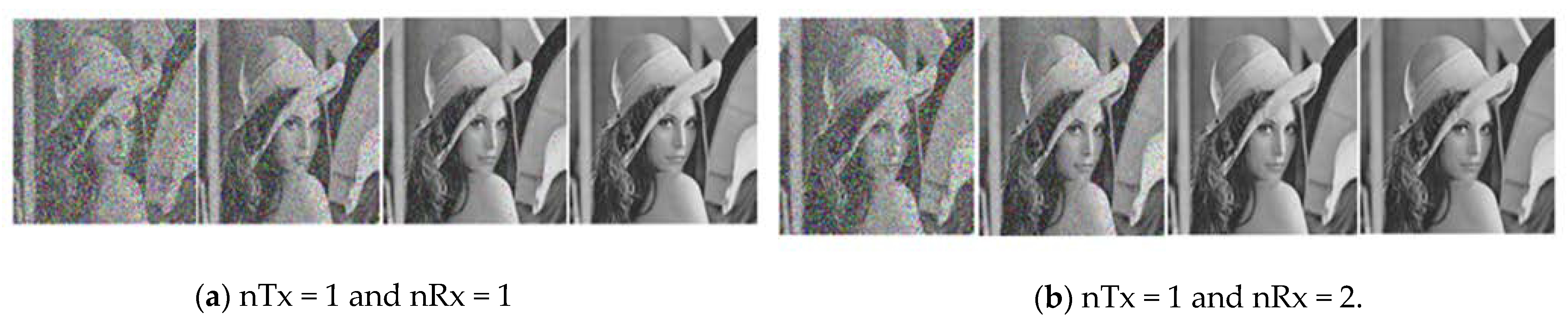
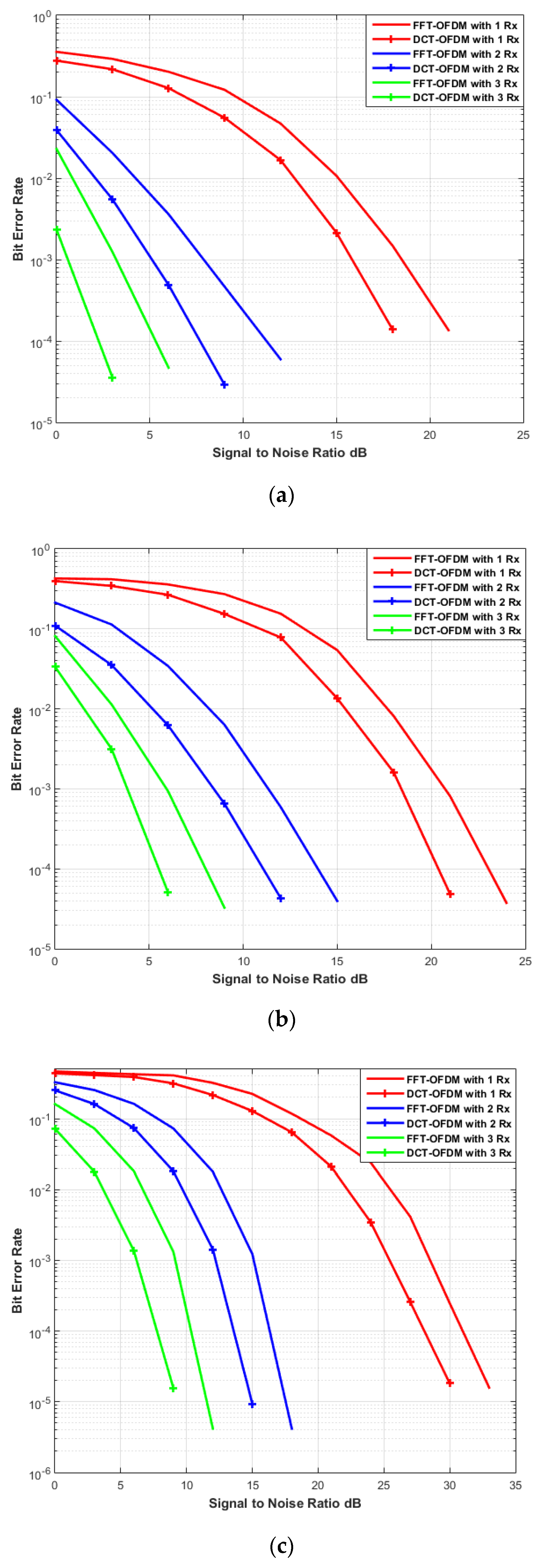
- DCT transform is being utilized to improve the BER performance in place of Fourier transform in the OFDM system for efficient transmission of the image.
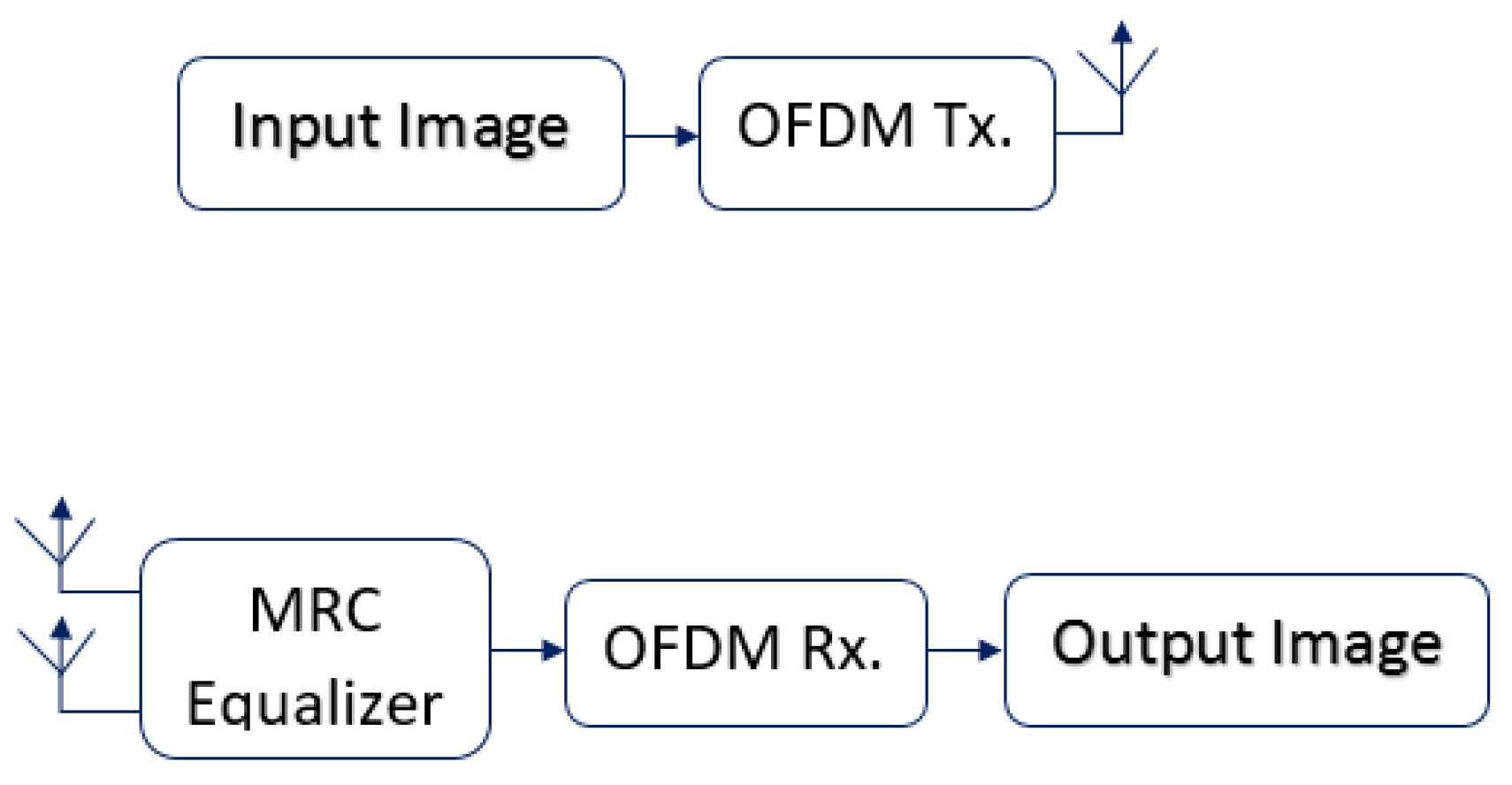
- A hybrid combination of MIMO-OFDM system is presented as a valid alternative to the conventional OFDM system for image transmission.
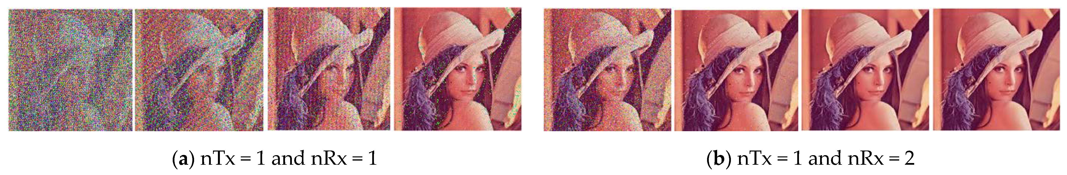
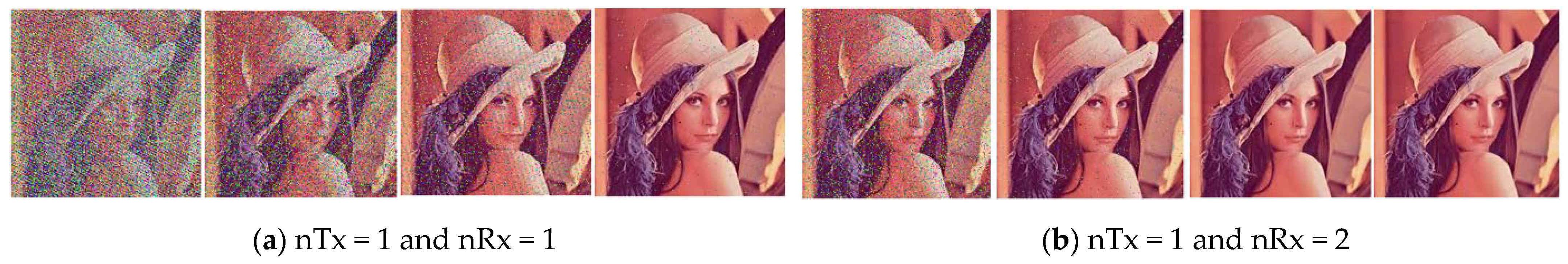
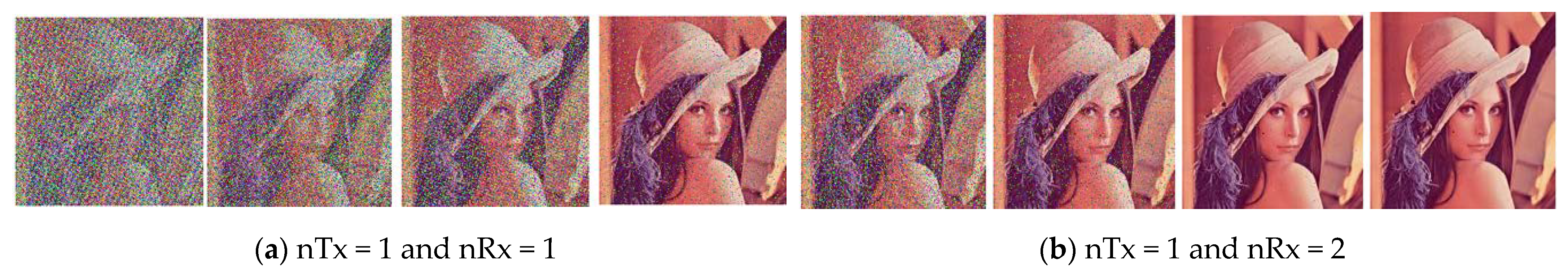
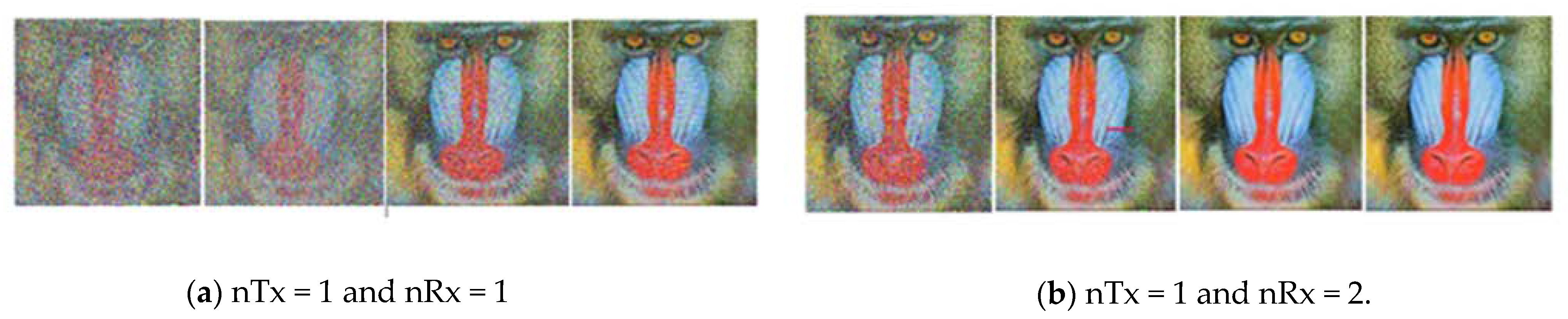
- The numbers of antennas are varied at the receiver side to access the MIMO-OFDM system’s performance and incorporate diverse transforms for multimedia applications.
3. Model Description
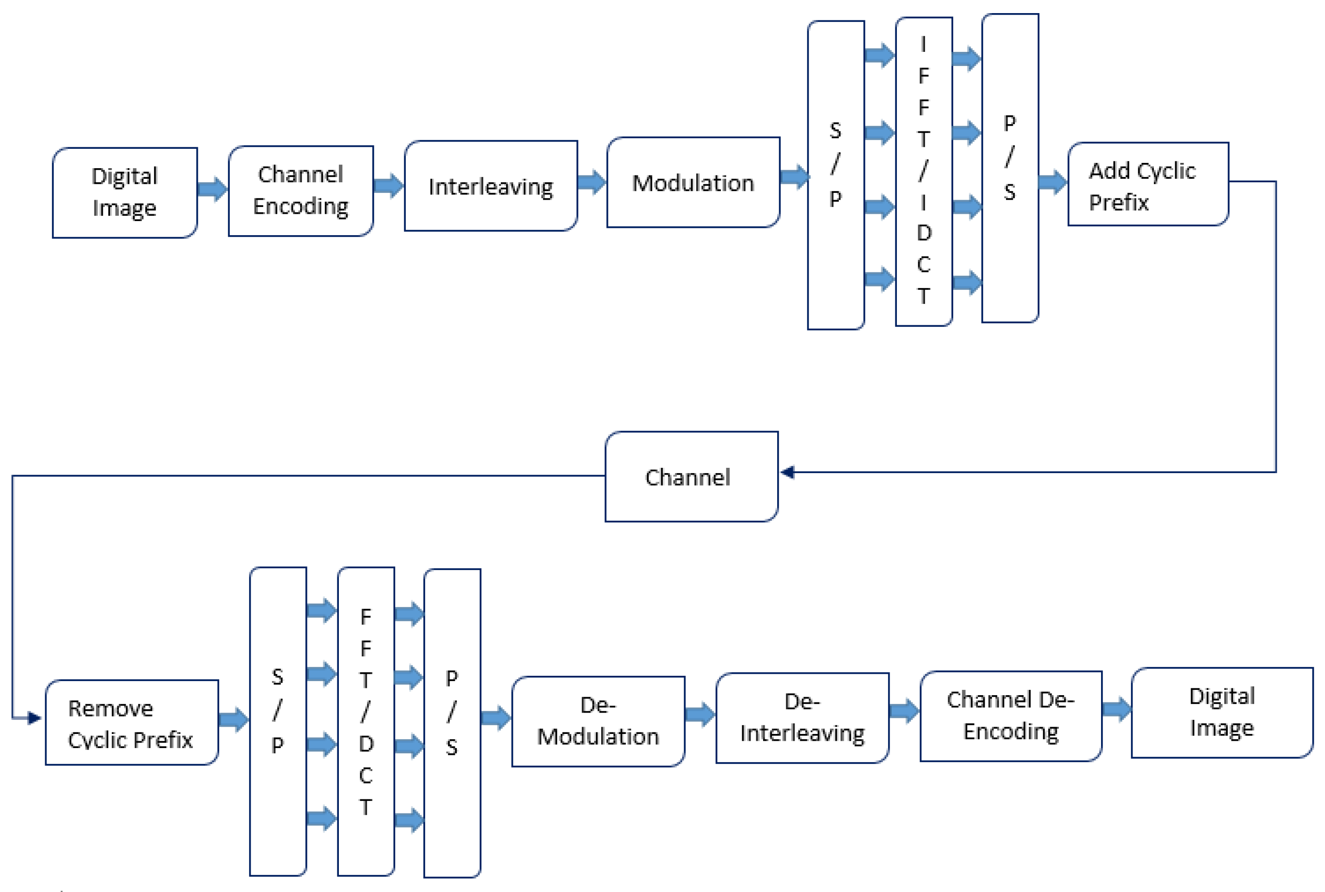
3.1. FFT-OFDM System Model
3.2. DCT-OFDM System Model
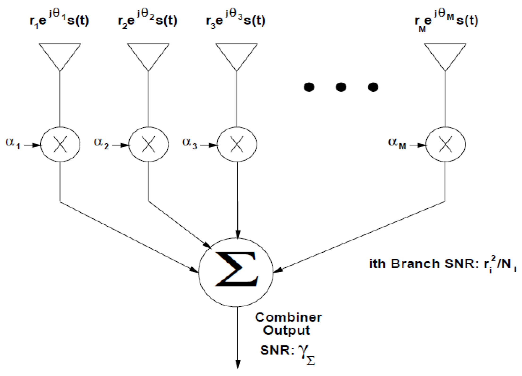
3.3. Maximal Ratio Combining (MRC)
4. Proposed System Model and Parameters
5. Result Analysis and Discussion
6. Conclusions and Future Scope
Author Contributions
Funding
Informed Consent Statement
Data Availability Statement
Conflicts of Interest
References
- Banelli, P.; Colavolpe, G.; Rugini, L.; Ugolini, A. Spectral Efficiency of Multicarrier Schemes for 5G. In Proceedings of the 2019 26th International Conference on Telecommunications (ICT), Hanoi, Vietnam, 8–10 April 2019; pp. 124–129. [Google Scholar]
- Foschini, G.J.; Salz, J. Digital communications over fading radio channels. Bell Syst. Tech. J. 1983, 62, 429–456. [Google Scholar] [CrossRef]
- Brennan, D.G. Linear diversity combining techniques. Proc. IEEE 2003, 91, 331–356. [Google Scholar] [CrossRef]
- Gans, M. The effect of Gaussian error in maximal ratio combiners. IEEE Trans. Commun. Technol. 1971, 19, 492–500. [Google Scholar] [CrossRef]
- Chyi, G.T.; Proakis, J.G.; Keller, C.M. On the symbol error probability of maximum-selection diversity reception schemes over a Rayleigh fading channel. IEEE Trans. Commun. 1989, 37, 79–83. [Google Scholar] [CrossRef]
- Winters, J.H.; Salz, J.; Gitlin, R.D. The impact of antenna diversity on the capacity of wireless communication systems. IEEE Trans. Commun. 1994, 42, 1740–1751. [Google Scholar] [CrossRef] [Green Version]
- Wan, Y.; Chen, J.C. Fading distribution of diversity techniques with correlated channels. In Proceedings of the International Symposium on Personal, Indoor and Mobile Radio Communications, Toronto, ON, Canada, 27–29 September 1995; pp. 1202–1206. [Google Scholar]
- Cui, J.; Falconer, D.D.; Sheikh, A.U.H. The analysis of BER for opti-mum combining with two co-channel interferers and maximal ratio combining with arbitrary number of interferers. In Proceedings of the International Symposium on Personal, Indoor and Mobile Radio Communications, Taipei, Taiwan, 18 October 1996; pp. 53–57. [Google Scholar]
- Zhang, Q.T. Probability of error for equal-gain combiners over Rayleigh channels: Some closed-form solutions. IEEE Trans. Commun. 1997, 45, 270–273. [Google Scholar] [CrossRef]
- Cui, J.; Falconer, D.D.; Sheikh, A.U.H. BER analysis of optimum combining and maximal ratio combining with channel correlation for dual antenna systems. In Proceedings of the Vehicular Technology Conference, Phoenix, AZ, USA, 4–7 May 1997; pp. 150–154. [Google Scholar]
- Lo, T.K. Maximum ratio transmission. In Proceedings of the 1999 IEEE International Conference on Communications, Vancouver, BC, Canada, 6–10 June 1999; pp. 1310–1314. [Google Scholar]
- Win, M.Z.; Winters, J.H. Analysis of hybrid selection/maximal-ratio combining in Rayleigh fading. In Proceedings of the IEEE Conference on Communication, Vancouver, BC, Canada, 6–10 June 1999; pp. 1773–1776. [Google Scholar]
- Thoen, S.; Van der Perre, L.; Gyselinckx, B.; Engels, M. Performance analysis of combined transmit-SC/receive-MRC. IEEE Trans. Commun. 2001, 49, 5–8. [Google Scholar] [CrossRef]
- Win, M.Z.; Winters, J.H. Virtual branch analysis of symbol error probability for hybrid selection/maximal-ratio combining in Rayleigh fading. IEEE Trans. Commun. 2001, 49, 1926–1934. [Google Scholar] [CrossRef]
- Molisch, A.F.; Win, M.Z.; Winters, J.H. Reduced-complexity transmit/receive-diversity systems. IEEE Trans. Signal Process. 2003, 51, 2729–2738. [Google Scholar] [CrossRef]
- Chen, Z.; Yuan, J.; Vucetic, B. Analysis of transmit antenna selection/maximal-ratio combining in Rayleigh fading channels. IEEE Trans. Veh. Technol. 2005, 54, 1312–1321. [Google Scholar] [CrossRef]
- Tang, J.; Zhang, X. Transmit selection diversity with maximal-ratio combining for multicarrier DS-CDMA wireless networks over Nakagami-m fading channels. IEEE J. Sel. Areas Commun. 2005, 24, 104–112. [Google Scholar] [CrossRef]
- Wang, B. Accurate BER of transmitter antenna selection/receiver-MRC over arbitrarily correlated Nakagami fading channels. In Proceedings of the IEEE International Conference on Acoustics Speech and Signal Processing, Toulouse, France, 14–19 May 2006; pp. 753–756. [Google Scholar]
- Kang, M.; Alouini, M.S. Performance Analysis of MIMO MRC Systems over Rician Fading Channels. In Proceedings of the IEEE Vehicular Technology Conference, Vancouver, BC, Canada, 24–28 September 2002; pp. 869–873. [Google Scholar]
- Cheng, J.; Berger, T. Performance analysis for MRC and post defection EGC over generalized gamma fading channels. In Proceedings of the IEEE Wireless Communication and Networking Conference, New Orleans, LA, USA, 16–20 March 2003; pp. 120–125. [Google Scholar]
- Al-Dhahir, N.; Minn, H. A new multicarrier transceiver based on the discrete cosine transform. In Proceedings of the IEEE Wireless Communications and Networking Conference, New Orleans, LA, USA, 13–17 March 2005; pp. 45–50. [Google Scholar]
- Aalo, V.A.; Piboongungon, T.; Efthymoglou, G.P. Another look at the performance of MRC schemes in Nakagami-m fading channels with arbitrary parameters. IEEE Trans. Commun. 2005, 53, 2002–2005. [Google Scholar] [CrossRef]
- Tan, P.; Beaulieu, N.C. Precise bit error probability analysis of DCT OFDM in the presence of carrier frequency offset on AWGN channels. In Proceedings of the IEEE Global Telecommunication Conference, St. Louis, MO, USA, 28 November–2 December 2005; pp. 1429–1434. [Google Scholar]
- Tan, P.; Beaulieu, N.C. A comparison of DCT-based OFDM and DFT-based OFDM in frequency offset and fading channels. IEEE Trans. Commun. 2006, 54, 2113–2125. [Google Scholar] [CrossRef]
- Tan, P.; Beaulieu, N.C. An improved DCT-based OFDM data transmission scheme. In Proceedings of the International Symposium on Personal, Indoor and Mobile Radio Communications, Berlin, Germany, 11–14 September 2005; pp. 745–749. [Google Scholar]
- Gupta, D.; Vats, V.B.; Garg, K.K. Performance analysis of DFT-OFDM, DCT-OFDM, and DWT-OFDM systems in AWGN. In Proceedings of the IEEE 4th International Conference on Wireless and Mobile Communications, Athens, Greece, 27 July–1 August 2008; pp. 214–216. [Google Scholar]
- Lin, S.C. Performance analysis for optimum transmission and comparison with maximal ratio transmission for MIMO systems with cochannel interference. EURASIP J. Wirel. Commun. Netw. 2011, 2011, 89. [Google Scholar] [CrossRef] [Green Version]
- Ullah, M.S.; Uddin, M.J. Performance analysis of wireless MIMO system by using Alamouti’s scheme and maximum ratio combining technique. Int. J. Adv. Eng. Sci. Technol. 2011, 8, 19–24. [Google Scholar]
- Eldin, S.M.S. Optimized OFDM transmission of encrypted image over fading channel. Sens. Imaging 2014, 15, 99. [Google Scholar] [CrossRef]
- Soliman, N.F.; Hassan, E.S.; Shaalan, A.H.A.; Fouad, M.M.; El-Khamy, S.E.; Albagory, Y.; El-Bendary, M.A.; Al-Hanafy, W.; El-Rabaie, E.S.M.; Dessouky, M.I.; et al. Efficient image communication in PAPR distortion cases. Wirel. Pers. Commun. 2015, 83, 2773–2834. [Google Scholar] [CrossRef]
- Kansal, L.; Sharma, V.; Singh, J. Performance assessment of precoded OFDM using discrete cosine-based DOST transform. Optik 2016, 127, 7242–7249. [Google Scholar] [CrossRef]
- Kansal, L.; Sharma, V.; Singh, J. BER assessment of FFT-OFDM against WHT-OFDM over different fading channel. Wirel. Netw. 2017, 23, 2189–2196. [Google Scholar] [CrossRef]
- Wang, Z.; Chen, F.; Qiu, W.; Chen, S.; Ren, D. A two layer chaotic encryption scheme of secure image transmission for DCT precoded OFDM-VLC transmission. Opt. Commun. 2018, 410, 94–101. [Google Scholar] [CrossRef]
- Agarwal, A.; Kumar, B.S.; Agarwal, K. BER Performance Analysis of Image Transmission Using OFDM Technique in Different Channel Conditions Using Various Modulation Techniques. In Computational Intelligence in Data Mining; Advances in Intelligent Systems and Computing; Springer: Singapore, 2018; pp. 1–8. [Google Scholar]
- Khaliluzzaman, M.; Pervin, S.; Ima, U.M.; Chy, D.K. DWT and DCT-Based Compressed Image Transmission Over AWGN Using C-QAM. In Emerging Technologies in Data Mining and Information Security; Advances in Intelligent Systems and Computing; Springer: Singapore, 2018; pp. 337–351. [Google Scholar]
- Rammyaa, B.; Vishvaksenan, K.S.; Poobal, S. Performance of spectrum sharing cognitive radio network based on MIMO MC-CDMA system for medical image transmission. Clust. Comput. 2019, 22, 7705–7712. [Google Scholar] [CrossRef]
- Kansal, L.; Sharma, V.; Singh, J. Multiuser Massive MIMO-OFDM System Incorporated with Diverse Transformation for 5G Applications. Wirel. Pers. Commun. 2019, 109, 2741–2756. [Google Scholar] [CrossRef]
- Yang, J.; Wang, C.; Jiang, B.; Song, H.; Meng, Q. Visual Perception Enabled Industry Intelligence: State of the Art, Challenges and Prospects. IEEE Trans. Ind. Inform. 2020, 17, 2204–2219. [Google Scholar] [CrossRef]
- Wen, J.; Yang, J.; Jiang, B.; Song, H.; Wang, H. Big Data Driven Marine Environment Information Forecasting: A Time Series Prediction Network. IEEE Trans. Fuzzy Syst. 2020, 29, 4–18. [Google Scholar] [CrossRef]


| Article | Research Outcome |
|---|---|
| BER Performance Analysis of Image Transmission Using OFDM Technique in Different Channel Conditions Using Various Modulation Techniques, Computational Intelligence in Data Mining. | This paper discussed the BER performance analysis of Image Transmission over conventional OFDM system using various modulation technique. The present manuscript presents the BER performance analysis of MIMO-OFDM system, which makes it more appropriate for the current application requirements of 5G systems. |
| A two layer chaotic encryption scheme of secure image transmission for DCT precoded OFDM-VLC transmission. | In this paper, a two-layer image encryption scheme for a discrete cosine transform (DCT) pre-coded orthogonal frequency division multiplexing (OFDM) visible light communication (VLC) system is proposed. The present manuscript also utilized the concept of DCT pre-coded OFDM system, but it has been analyzed over radio channel and by employing multiple antennas at receiver side. Additionally, in addition to using BER performance as comparison metric, PSNR vs. SNR and SSIM are also used to present the reliability of the proposed methodology. |
| Performance assessment of pre-coded OFDM using discrete cosine-based DOST transform. | In this research article an innovative precoding method has been proposed based on Discrete Cosine-based DOST (DCST) to lessen the High PAPR values and BER in OFDM systems. A similar concept of precoding is being utilized in the present manuscript with the use of DCT instead of DCST transform. Moreover, the analysis is carried out by utilizing the image transmission methodology instead of generic data sequences. |
| Optimized OFDM transmission of encrypted image over fading channel. | This paper compares the quality of diffusion-based and permutation-based encrypted image transmission using orthogonal frequency division multiplexing (OFDM) over wireless fading channel. In the present manuscript, no encryption is being utilized. The comparison of the quality of transmitted and received image is carried out with the help of SSIM metric. |
| SNR | FFT-OFDM | DCT-OFDM | ||
|---|---|---|---|---|
| 1 Tx and 1 Rx | 1 Tx and 2 Rx | 1 Tx and 1 Rx | 1 Tx and 2 Rx | |
| 0 dB | 9.33109 | 15.8195 | 10.8239 | 21.1769 |
| 5 dB | 11.1558 | 27.0993 | 12.1698 | 42.7428 |
| 10 dB | 14.3648 | 58.0264 | 19.2917 | 60.2544 |
| 15 dB | 22.5041 | 69.4254 | 36.3608 | 73.5611 |
| SNR | FFT-OFDM | DCT-OFDM | ||
|---|---|---|---|---|
| 1 Tx and 1 Rx | 1 Tx and 2 Rx | 1 Tx and 1 Rx | 1 Tx and 2 Rx | |
| 0 dB | 9.9119 | 16.0626 | 10.4111 | 21.2002 |
| 5 dB | 11.5252 | 26.9213 | 12.8423 | 44.3806 |
| 10 dB | 13.0074 | 59.5812 | 17.4532 | 62.5781 |
| 15 dB | 23.8034 | 70.2641 | 29.1656 | 76.5459 |
| SNR | FFT-OFDM | DCT-OFDM | ||
|---|---|---|---|---|
| 1 Tx and 1 Rx | 1 Tx and 2 Rx | 1 Tx and 1 Rx | 1 Tx and 2 Rx | |
| 0 dB | 9.2832 | 12.5852 | 9.5323 | 13.5347 |
| 5 dB | 10.309 | 18.1539 | 10.616 | 20.5674 |
| 10 dB | 12.3526 | 32.8267 | 12.5531 | 42.1449 |
| 15 dB | 16.4483 | 59.4964 | 16.747 | 64.5412 |
| SNR | FFT-OFDM | DCT-OFDM | ||
|---|---|---|---|---|
| 1 Tx and 1 Rx | 1 Tx and 2 Rx | 1 Tx and 1 Rx | 1 Tx and 2 Rx | |
| 0 dB | 10.944 | 18.0643 | 11.688 | 20.7696 |
| 5 dB | 11.7248 | 22.4797 | 13.3363 | 25.7564 |
| 10 dB | 16.9373 | 28.995 | 20.5709 | 36.2319 |
| 15 dB | 21.3388 | 45.3092 | 24.427 | 70.0577 |
| SNR | FFT-OFDM | DCT-OFDM | ||
|---|---|---|---|---|
| 1 Tx and 1 Rx | 1 Tx and 2 Rx | 1 Tx and 1 Rx | 1 Tx and 2 Rx | |
| 0 dB | 8.5157 | 12.78663 | 10.1498 | 16.5133 |
| 5 dB | 10.1206 | 18.3998 | 11.7852 | 26.032 |
| 10 dB | 12.9643 | 34.54 | 15.559 | 56.4358 |
| 15 dB | 18.8008 | 54.3651 | 22.734 | 72.1541 |
| SNR | FFT-OFDM | DCT-OFDM | ||
|---|---|---|---|---|
| 1 Tx and 1 Rx | 1 Tx and 2 Rx | 1 Tx and 1 Rx | 1 Tx and 2 Rx | |
| 0 dB | 9.6355 | 12.8861 | 9.9624 | 15.7346 |
| 5 dB | 10.5961 | 18.7141 | 12.1718 | 26.1021 |
| 10 dB | 19.331 | 34.0961 | 15.009 | 61.4828 |
| 15 dB | 19.037 | 53.1652 | 27.8149 | 76.5221 |
| SNR | FFT-OFDM | DCT-OFDM | ||
|---|---|---|---|---|
| 1 Tx and 1 Rx | 1 Tx and 2 Rx | 1 Tx and 1 Rx | 1 Tx and 2 Rx | |
| 0 dB | 9.2219 | 10.9362 | 9.228 | 11.4612 |
| 5 dB | 9.8334 | 13.8928 | 10.0164 | 15.2007 |
| 10 dB | 11.2669 | 21.5332 | 11.4974 | 25.1824 |
| 15 dB | 14.2133 | 43.1082 | 15.151 | 49.9177 |
| SNR | FFT-OFDM | DCT-OFDM | ||
|---|---|---|---|---|
| 1 Tx and 1 Rx | 1 Tx and 2 Rx | 1 Tx and 1 Rx | 1 Tx and 2 Rx | |
| 0 dB | 10.4532 | 15.135 | 10.9457 | 17.853 |
| 5 dB | 11.7834 | 19.6491 | 13.9493 | 22.3086 |
| 10 dB | 14.6304 | 24.1127 | 18.4043 | 28.286 |
| 15 dB | 20.1877 | 32.447 | 22.2489 | 43.1996 |
| System | Antenna Configuration | SNR = 0 dB | SNR = 5 dB | SNR = 10 dB | SNR = 15 dB | ||||
|---|---|---|---|---|---|---|---|---|---|
| PSNR | SSIM | PSNR | SSIM | PSNR | SSIM | PSNR | SSIM | ||
| FFT-OFDM | 1 Tx and 1 Rx | 9.76543 | 0.03915 | 10.705663 | 0.07199 | 11.58676 | 0.111477 | 15.3062 | 0.2962 |
| 1 Tx and 2 Rx | 11.9468 | 0.12827 | 15.321285 | 0.3044454 | 23.93093 | 0.775219 | 51.2156 | 0.9994 | |
| 1 Tx and 3 Rx | 13.2219 | 0.1910 | 18.5414 | 0.4963 | 32.5573 | 0.9624 | 73.2458 | 1.0000 | |
| DCT-OFDM | 1 Tx and 1 Rx | 9.67864 | 0.04332 | 9.6975001 | 0.0227244 | 14.11069 | 0.236522 | 20.5423 | 0.6079 |
| 1 Tx and 2 Rx | 13.5783 | 0.2069 | 19.38939 | 0.545288 | 35.45733 | 0.980889 | 78.4622 | 1 | |
| 1 Tx and 3 Rx | 15.8745 | 0.3314 | 25.2924 | 0.8255 | 56.8592 | 0.9998 | 87.5695 | 1.0000 | |
| System | Antenna Configuration | SNR = 0 dB | SNR = 5 dB | SNR = 10 dB | SNR = 15 dB | ||||
|---|---|---|---|---|---|---|---|---|---|
| PSNR | SSIM | PSNR | SSIM | PSNR | SSIM | PSNR | SSIM | ||
| FFT-OFDM | 1 Tx and 1 Rx | 9.89905 | 0.0293 | 10.592833 | 0.0430585 | 11.81925 | 0.085431 | 15.504 | 0.21941 |
| 1 Tx and 2 Rx | 12.0372 | 0.0938 | 15.224939 | 0.211088 | 23.72912 | 0.646574 | 48.3271 | 0.99792 | |
| 1 Tx and 3 Rx | 13.2472 | 0.1336 | 18.4498 | 0.3581 | 32.2927 | 0.9355 | 72.4842 | 1.0000 | |
| DCT-OFDM | 1 Tx and 1 Rx | 10.2949 | 0.0411 | 11.182142 | 0.0651304 | 12.34516 | 0.119801 | 18.1675 | 0.33916 |
| 1 Tx and 2 Rx | 13.5942 | 0.1467 | 19.413126 | 0.4074441 | 35.84002 | 0.964057 | 78.6842 | 1 | |
| 1 Tx and 3 Rx | 15.8437 | 0.2359 | 25.1688 | 0.7168 | 48.3627 | 0.9988 | 85.9384 | 1.0000 | |
Publisher’s Note: MDPI stays neutral with regard to jurisdictional claims in published maps and institutional affiliations. |
© 2021 by the authors. Licensee MDPI, Basel, Switzerland. This article is an open access article distributed under the terms and conditions of the Creative Commons Attribution (CC BY) license (https://creativecommons.org/licenses/by/4.0/).
Share and Cite
Kansal, L.; Gaba, G.S.; Chilamkurti, N.; Kim, B.-G. Efficient and Robust Image Communication Techniques for 5G Applications in Smart Cities. Energies 2021, 14, 3986. https://doi.org/10.3390/en14133986
Kansal L, Gaba GS, Chilamkurti N, Kim B-G. Efficient and Robust Image Communication Techniques for 5G Applications in Smart Cities. Energies. 2021; 14(13):3986. https://doi.org/10.3390/en14133986
Chicago/Turabian StyleKansal, Lavish, Gurjot Singh Gaba, Naveen Chilamkurti, and Byung-Gyu Kim. 2021. "Efficient and Robust Image Communication Techniques for 5G Applications in Smart Cities" Energies 14, no. 13: 3986. https://doi.org/10.3390/en14133986
APA StyleKansal, L., Gaba, G. S., Chilamkurti, N., & Kim, B.-G. (2021). Efficient and Robust Image Communication Techniques for 5G Applications in Smart Cities. Energies, 14(13), 3986. https://doi.org/10.3390/en14133986