Abstract
In isolated areas such as islands with small power grids, the BESS (Battery energy storage system) can supply the standard voltage and frequency to the power system to achieve 100% of renewable sharing. In addition, the installation of additional BESS may be required in the microgrid due to technical limitations such as redundant operation and manufacturer specifications. Thus, the BESSs in a microgrid can be split into main and sub BESSs which play a role as the main source and auxiliary services, respectively. Generally, the ratio of unbalance current in microgrid system tends to be high, because of inherently unbalanced single phase load distribution. However, because the capacity of BESS is calculated under balanced conditions, the PCS (Power conversion system) of BESS may stop protecting its switching device from a single phase overcurrent in actual operation. From this perspective, this paper proposes that the sub BESSs perform dual current control to supply the unbalanced current instead of the main BESS. In the simulation result of the proposed method, the current unbalance rate of the main ESS has been reduced by about 26%. Through the proposed control scheme, it is possible to prevent an unexpected single phase overload of the main BESS in the microgrid.
1. Introduction
Worldwide, countries are expanding the construction of renewable energy sources from existing power systems to target greenhouse gas reductions. In particular, in areas such as islands composed of small-scale independent power grids, BESS provides the voltage and frequency to the grid, rather than the existing rotating machine base operating the power system to supply power only with renewable energy [1,2,3,4,5,6,7]. In the study of “Decentralised Active Power Control Strategy for Real-Time Power Balance in an Isolated Microgrid with an Energy Storage System and Diesel Generators”, the system was operated using a droop control method that controls voltage and frequency without a communication line through active and reactive power output from the inverter [8]. In addition, Qunhai Huo et al. researched a method of supplying a constant voltage and frequency to the load regardless of renewable energy fluctuations and load changes through CVCF control of PCS [9]. Therefore, in order to supply power to the load with 100% renewable energy, the above BESS control is necessary. Additionally, due to technical limitations such as the failure of the mBESS, the manufacturer’s capacity, and inverter parallel operation control, it may be necessary to install auxiliary BESS in the microgrid.
Some poorly constructed microgrids have unbalanced loads. However, when designing the capacity of BESS, it is calculated by considering the system balanced. As a result, an unbalanced current flows into the PCS suitably designed according to the power load capacity, and the protection operations of the switching device may occur. If the PCS of the mBESS stops the switching, the power system will experience a blackout. For this reason, a stable operation plan for mBESS is needed to achieve 100% of the renewable energy independence rate in the future. Currently, several inspiring studies have been proposed to resolve the unbalancing of microgrids. A. Ranjbaran et al. proposed a control strategy to adjust the droop curve of each phase in real time according to the load fluctuation and to alleviate the voltage unbalance of PCC [10]. Biying Ren et al. presented a droop control method based on the droop curve and impedance drop compensation in order to improve the adverse effects caused by numerous single-phase loads in the microgrid [11]. Foad Najafi et al. used a zero-sequence and negative-sequence virtual impedance controller to improve sharing of unbalanced currents in islanded microgrids [12]. Xiaorong Zhu et al. studied a control strategy of DC bus voltage ripple suppression using super capacitors in consideration of the unbalanced load condition [13]. Mohammad Jafar Hadidian Moghaddam et al. proposed an improved control scheme for a 4-leg battery energy storage system under unbalanced and nonlinear load conditions operating in microgrids [14]. In Hongtao Shi’s paper, an integrated compensation strategy consisting of a negative compensation controller was suggested to suppress the unbalanced voltage and fluctuations for an unbalanced isolated microgrid [15]. However, research on unbalanced compensation using sBESS is insufficient. From this perspective, this paper proposes a method to reduce the unbalance rate of the current supplied by the mESS through the DCC of the sBESS under the microgrid unbalanced load condition [16,17,18,19,20]. To achieve this, the NSC supplied by mBESS was calculated using the symmetric coordinate method, and the calculated NSC is supplied by sBESS instead, reducing the current unbalance rate of the mBESS [21]. In conclusion, there is no overload on one phase of the mBESS, enabling stable microgrid operation.
To verify the effectiveness of the proposed method, as shown in Figure 1, Floreana Island in the Galapagos Islands near South America was modeled using the PSCAD/EMTDC system analysis tool. The example microgrid was installed with distributed resources, including 140 kW diesel generators, a 900 kWh BESS and 200 kWp PVs.
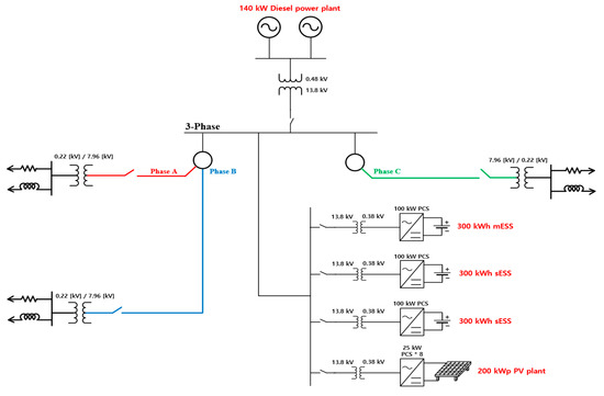
Figure 1.
Overview of Floreana Island power system.
In fact, the average load on Floreana Island is about 46 kW. Among the three-phase loads, phase A consists of 41%, phase B 14%, and phase C 46%. If the annual average load increase rate of 5% is considered, the average load will be about 59 kW after 5 years, and the maximum load will be about 84 kW. On cloudy days or early mornings without solar power, there may be a problem, especially in the C phase load, which can exceed at least 34 kW. Although the capacity of the three-phase load is 84 kW, which does not exceed 100 kW, the PCS capacity of the mBESS, there is a concern that mBESS operation will be stopped because the C phase capacity exceeds 33 kW. This problem is not found in the initial construction stage of the proposed microgrid, but it is a problem that may actually appear depending on the load increase and system conditions. Consequently, in this paper, the proposed method proves the effect of preventing overload by reducing the current unbalance rate of the mBESS in Floreana Island.
2. Basic and Proposed Control Theory
Among the distributed power of microgrid, PCS is connected to facilities such as PV and ESS. The PCS connected to PV and ESS in this paper is modeled as a two-level type consisting of 6 IGBTs as shown in Figure 2. In addition, L and C filters were calculated to suit the capacity of each PCS and designed to be less than 5% THD [22,23,24].
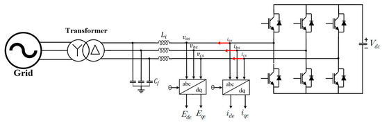
Figure 2.
Two-level inverter simulation model.
In particular, the current controller of the sBESS was set as the following two models and reflected in the computer analysis. One is a general controller model, and the other is a controller model to prevent overload of the mBESS under unbalanced load conditions.
2.1. Conventional sBESS Control Method
Figure 3 is a block diagram of a current controller applied to a general sBESS. After calculating the dq-axis terminal voltage of the two-level inverter through Park’s conversion, and applying the PI controller considering the overshoot and rise time, it can be expressed as Equations (1) and (2) [25,26]. In this equation, the dq command current was set as in Equations (3) and (4). and is controlled so that the active power of the mBESS is output as 0 MW and the reactive power is always 0 MVar within the range of the upper and lower limits of the sBESS SoC.
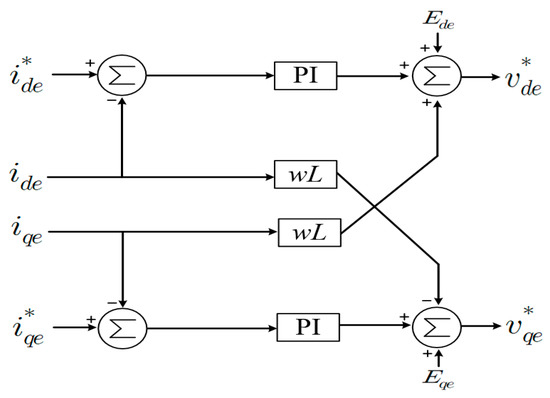
Figure 3.
Control diagram of the current.
2.2. Proposed sBESS Control Method
The model of Floreana Island in the Galapagos that is used in this paper is composed of unbalanced loads. Due to this, irregular phases of voltage and current are generated, causing three-phase unbalance. The voltage and current in an unbalanced system are composed of positive, negative, and zero sequence, and each can be expressed independently through the symmetric coordinate method. As shown in Equations (5) and (6), the PSV and NSV can be calculated. In the case of the zero sequence, it was not controlled because it circulates inside the ∆ connection using a Y-∆ transformer. The three-phase current can also be expressed in the same way as the PSV and NSV in the above equation.
The PSV, NSV, PSC and NSC calculated in the sBESS are independently controlled as shown in Figure 4 and Figure 5. In the same way as general inverter control current equations, the PSC and NSC equations can also be expressed as Equations (7)–(10). In Equations (7) and (8), the command values are defined and controlled as shown in Equations (11) and (12). Active and reactive power can be controlled as mentioned in Equations (3) and (4). In general negative sequence control, are controlled to 0. However, in the proposed method, the current controller of the command value is expressed by Equations (13) and (14). In this equation, integral control is performed so that follows 0. Through this, sBESS compensates for the NSC of the mBESS. This means that sBESS supplies NSC instead of the mBESS. z in Equations (11)–(14) means the number of inverters of the sBESS, and each inverter can control the power of the mBESS equally. By applying the proposed method, the mBESS supplies a balanced three-phase current. From this operation, one-phase overload does not occur, the PCS can prevent the overcurrent tripping of IGBT. The PSV and NSV command values derived through the DCC are summed in the stationary reference frame as shown in Figure 6. The combined value is converted to three-phase abc voltage and output as the command value of each phase.
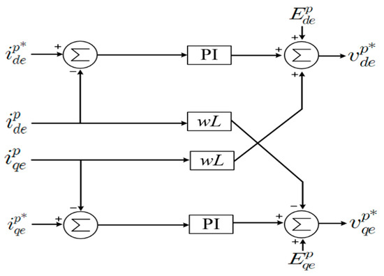
Figure 4.
Control diagram of the positive sequence current (PSC).
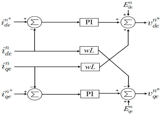
Figure 5.
Control diagram of the negative sequence current (NSC).
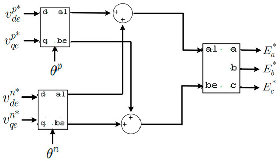
Figure 6.
3-phase conversion of stationary reference frame.
3. PSCAD/EMTDC Simulation Modeling
Figure 7 shows the PSCAD/EMTDC simulation modeling of the entirety of Floreana Island. A 140 kW diesel power plant, 200 kW PV plant and 900 kWh ESS were designed. In addition, it was designed in detail considering the actual line length and power load. As mentioned above, the phase C load is the largest, composed of about 46% of the total load. In Figure 7, it can be seen that the phase C load is the largest even in the three phase indications. Additionally, in this study, the diesel generator was not reflected in the computer analysis result because BESS operates to provide voltage and frequency to the system.
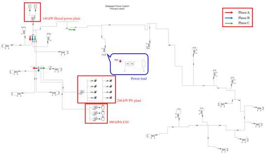
Figure 7.
Floreana island simulation model in PSCAD/EMTDC.
Figure 8 is an enlarged view of the PV power plant and the BESS side in Figure 7. It consists of a BESS connected with three 100 kW PCS units and a PV plant connected with eight 25 kW PCS units. One of the three BESSs performs CVCF control providing voltage and frequency to the grid. The other two are sBESS supporting mBESS, and in order to verify the proposed control, it is designed as shown in Figure 9 by reflecting Figure 4 and Figure 5 in the simulation modeling. BESS’s battery model used the library provided by PSCAD/EMTDC is indicated by the orange box. Figure 10 is a simulation model of a 25 kW PV. The PV module in the blue box is a library provided by PSCAD/ETMDC, and the input parameters, which are solar radiation and temperature data, were set as data actually measured in the Floreana Island. The DC/DC converter linked to the PV module performs MPPT control [27,28,29,30]. Additionally, the 25 kW inverter performs DC link voltage control to stably supply PV power to the grid [31,32].
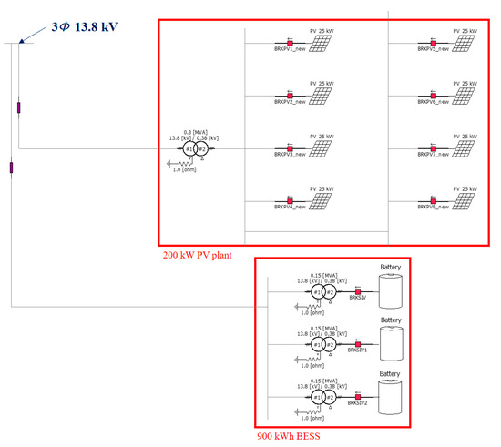
Figure 8.
Photovoltaic (PV) plant and battery energy storage system (BESS) simulation models in PSCAD/EMTDC.
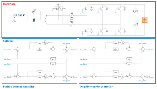
Figure 9.
Simulation model of sub-battery energy storage system (sBESS).
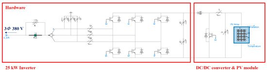
Figure 10.
Simulation model of PV.
The Floreana Island microgrid can be managed with the EMS logic shown in Figure 11. First of all, if the operation is stopped due to a malfunction or inspection of the mBESS, the sBESS should operate the system instead of the mBESS. If mBESS provides voltage and frequency to the grid, the logic varies according to the SoC of the mBESS. First, as shown in the red box, the PV generation amount must be limited so as not to exceed the SoC upper limit of the mBESS. If the SoC is over 80%, the PV output must be limited. For example, it means stopping PV inverters for the amount of excess generation among all PV inverters. Additionally, if the SoC is more than 90%, all PV generation must be stopped to ensure the stability of the mBESS. Second, a green boxlike logic is required so that the SoC of the mBESS does not fall below the lower limit. If there is no solar power generation and the SoC of the sBESS is lower than 20%, the mBESS alone may supply power to the load without assistance from other distributed power sources. Accordingly, the mBESS alone supplies the unbalanced current, and the inverter may stop operating due to an overload of one phase. In consideration of such a situation, in this paper, the proposed control is applied to the sBESS so that the mBESS can be balanced without causing a single phase overload.
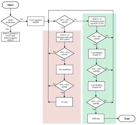
Figure 11.
Energy management system (EMS) flow chat in Floreana island.
4. Simulation Results
In Section 4, the simulation results are shown using PSCAD/EMTDC. Scenario 1 is the system operation result when the PV generation amount is larger than the load demand, as shown in the red box part in Figure 11. Scenario 2 considers the case where the SoC of the sBESS is less than 20% because there is no photovoltaic power generation under the condition of the green box part in Figure 11, and the mBESS alone supplies power to the unbalanced load. Table 1 express the active and reactive power results in Figure 12 and Figure 15.

Table 1.
Expressions of simulation results.
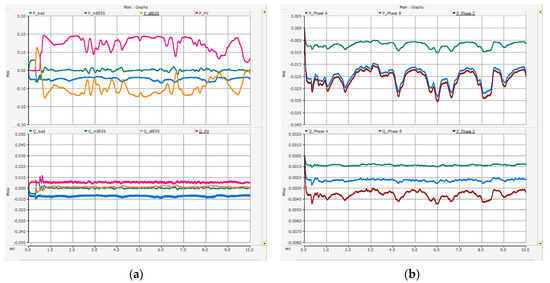
Figure 12.
Simulation results of Scenario 1 (a) Whole power system (top: active power; bottom: reactive power) and (b) load demand (top: active power for each phase; bottom: reactive power for each phase).
4.1. Scenario 1—Conventional sBESS Control
Figure 12a is the result of active and reactive power when all systems are operated. The PV output fluctuates as the actual insolation and temperature data are reflected. Since sBESS is controlled so that the active and reactive power of the mBESS is 0 MW, 0 MVar, it charges and discharges in response to PV output fluctuations instead of the mBESS. The load demand result of each phase of Floreana Island is shown in Figure 12b. Phase C of brown expression was the largest, with a maximum of about 37 kW, phase A (blue color) was 35 kW and phase B (green color) was about 12 kW. In addition, phase C consists of a transmission line that is longer than the other phases, as shown in the overall simulation model in Figure 7. Accordingly, there is a large difference in the value of reactive power.
As shown in Figure 13a, there is little change in the SoC of the mBESS through the auxiliary control of the sBESS. This means that even if there is no solar power generation, power can be supplied to the load for a long time by using the stored energy of the mBESS.
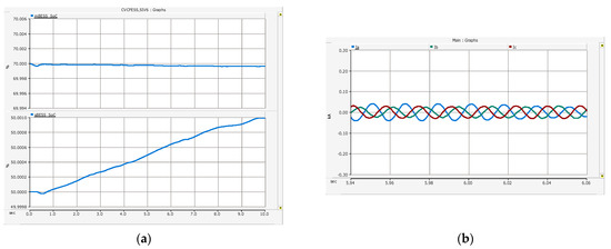
Figure 13.
Simulation results of Scenario 2 (a) State of charge (SoC) (top: SoC of Main Battery energy storage system(mBESS); bottom: SoC of the sBESS) and (b) instantneous three-phase current of the mBESS.
Figure 13b shows the result of the three-phase instantaneous current of the mBESS in about 6 s when the load demand is at its highest. The three-phase current is not balanced due to the unbalanced load. At this time, the maximum current of one phase is about 0.05 kA. Since the sBESS controls the output of the mBESS to 0, the overcurrent tripping of the mBESS does not occur. Figure 14 shows the PSV, NSV, PSC and PSV dq results of the mBESS. Due to the CVCF control, the three-phase voltage maintains a balance, and in the result shown in Figure 14a, the PSV on the q-axis is about 311 V, which is the maximum of the phase voltage, and the NSV is 0 V. Additionally, the change of the PSC is the same as the change of the mBESS active power in Figure 12a. Additionally, since unbalanced current control is not performed in Scenario 1, the mBESS supplies NSC as shown in Figure 14b.
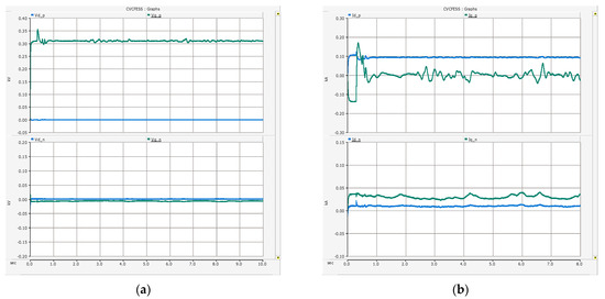
Figure 14.
Simulation results of Scenario 1 (a) mBESS (top: dq-axis PSV; bottom: dq-axis NSV) and (b) mBESS (top: dq-axis PSC; bottom: dq-axis NSC).
4.2. Scenario 2—Proposed sBESS Control
Scenario 2 assumes that there is no photovoltaic power generation, and the SoC of the sBESS is less than 20%, and the mBESS alone supplies power to the unbalanced load. The rated capacity of one phase of the mBESS is 33 kW, and the maximum instantaneous current is about 0.21 KA. However, as can be seen from Figure 15b, there are cases where the loads of the A and C phases exceed 33 kW. If PV does not generate power, the mBESS may supply more than the rated capacity of one phase. Accordingly, the operation of the mBESS may be stopped due to an overcurrent of one phase.
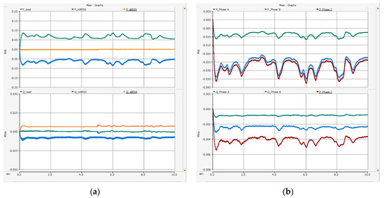
Figure 15.
Simulation results of Scenario 2 (a) Whole power system (top: active power; bottom: reactive power) and (b) load demand (top: active power for each phase; bottom: reactive power for each phase).
In order to prevent one-phase overcurrent of the mBESS, the sBESS operated in 5 s to perform DCC. To compare the three-phase instantaneous current before and after reflecting the double current control when the power load of one phase exceeds 33 kW, this is shown in Figure 16a,b. The maximum current of phase A (blue) in Figure 16a was about 0.23 kA, so one phase exceeded 33 kW. If the PCS supplies such an overcurrent, the switching will stop to protect the IGBT. However, as shown in Figure 16b, the three-phase instantaneous current of the mBESS can be balanced through the method proposed by sBESS. In addition, even if one phase exceeds 33 kW, as shown in the power value of 6 s in Figure 15b, the three-phase instantaneous current in Figure 16b does not exceed 0.21 kA, the maximum current, and the mBESS can be stably operated.
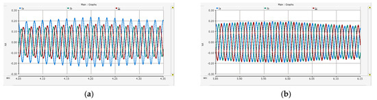
Figure 16.
Simulation results of Scenario 2 (a) instantaneous three-phase current of the mBESS before dual current control (DCC) and (b) instantaneous three-phase current of the mBESS after DCC.
In Figure 17a, the PSV and NSV results of the dq-axis are the same as in Scenario 1, the PSV on the q-axis is 311 V, which is the maximum value of the phase voltage, and the NSV is 0 V. In the result of Figure 17b, the PSC occurs as much as power is supplied to the load, and the NSC of the dq-axis converges to 0 A as DCC is performed in 5 s. Figure 18a is the result of PSC and NSC of one sBESS. Since only the negative sequence is controlled, the value of the PSC is maintained at 0 A, and the control starts in 5 s, and two sBESSs supply the NSC. Additionally, it can be seen from Figure 18b that two sBESSs share and supply the reverse phase current of the mBESS equally. In addition, since sBESS supplies only NSC, it hardly discharges, as shown in the SoC result of Figure 18a. This means that even if mBESS is operated alone, it will be able to stably operate the power system by supporting mBESS regardless of the SoC of the sBESS. In Figure 19b, after 5 s, the current unbalance rate of the mBESS became 4% and decreased by about 26% compared to before control.
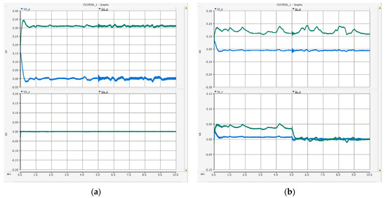
Figure 17.
Simulation results of Scenario 2 (a) mBESS (top: dq-axis PSV; bottom: dq-axis NSV) and (b) mBESS (top: dq-axis PSC; bottom: dq-axis NSC).
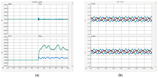
Figure 18.
Simulation results of Scenario 2 (a) sBESS (top: dq-axis PSC; bottom: dq-axis NSC) and (b) sBESS (top: instantaneous three-phase current of #1 sBESS; bottom: instantaneous three-phase current of #2 sBESS).
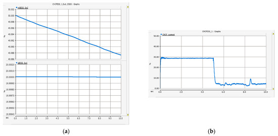
Figure 19.
Simulation results of Scenario 2 (a) SoC (top: SoC of the mBESS; bottom: SoC of the sBESS) and (b) current unbalance rate of the mBESS.
5. Discussion
As in the result analyzed in Scenario 1, despite the unbalanced load configuration of Floreana Island, PV is sufficiently developed, and through the auxiliary role of the sBESS, mBESS can operate stably without generating overcurrent in one phase. In practice, however, PV may not develop when operating a distributed power system. Accordingly, if the mBESS supplies power alone, the system may be stopped due to overcurrent in a specific phase in a microgrid with a severe unbalanced load such as Floreana Island. To prevent overcurrent of the mBESS, in Scenario 2, the sBESS performed the proposed control method. There was a maximum of 38 kW power demand in the C phase, but as shown in Table 2, the maximum value of the three-phase instantaneous current of the mBESS was 0.19 kA, not exceeding the rated maximum current of the phase 0.21 kA. In addition, the current unbalance rate of the mBESS improved by 26%. In addition, since there was little change in SoC in Figure 19, it is judged that a voltage-type inverter that uses capacitors other than BESS can solve the unbalance problem of the mBESS.
Table 2.
Instantaneous current and current unbalance rate of the mBESS.
6. Conclusions
In order to build a microgrid and supply power to the load with 100% renewable energy, the BESS must provide the constant voltage and frequency to the grid. Additionally, the sBESS is required due to technical limitations such as the failure of the mBESS, the capacity of manufacturers, and parallel operation control of inverters. In this paper, a microgrid on Floreana Island in the Galapagos Islands, which is composed of unbalanced loads, was designed through the PSCAD/EMTDC system analysis program. Furthermore, for the validity of the designed microgrid, actual power load data, line length, and PV data (insolation, temperature) were reflected. In Scenario 1, through the auxiliary control of the sBESS, even if there is no solar power generation, the energy stored in the mBESS can be used to supply power to the load for a long time. After the microgrid was built, we found a problem in Scenario 2 that was not found when all distributed power systems were operating normally. To solve the problem, DCC of the sBESS was performed, and accordingly, the maximum current of one phase of the mBESS was reduced by 0.04 kA and the current unbalance rate was reduced by 26%.
Therefore, if a microgrid is to be built in a system composed of unbalanced loads such as Floreana Island, problems that may occur in actual operation must be solved in the feasibility study stage as in this study.
Author Contributions
Conceptualization: E.-H.K.; methodology: H.S. and S.C.; resources: H.S., S.C., and E.-H.K.; writing—original draft preparation: H.S. and S.C.; writing—review and editing: H.S. and E.-H.K.; supervision: E.-H.K. All authors have read and agreed to the published version of the manuscript.
Funding
This research was funded the Korea Institute of Energy Technology Evaluation and Planning (KETEP).
Institutional Review Board Statement
Not applicable.
Informed Consent Statement
Not applicable.
Data Availability Statement
Not applicable.
Acknowledgments
This research was supported by the Korea Institute of Energy Technology Evaluation and Planning (Project number: 20194030202310 and 20184030202200).
Conflicts of Interest
The authors declare no conflict of interest.
Nomenclature
| d-axis terminal voltage | |
| q-axis terminal voltage | |
| d-axis grid voltage | |
| q-axis grid voltage | |
| d-axis current | |
| q-axis current | |
| Three phase grid voltages | |
| Positive sequence voltages | |
| Negative sequence voltages | |
| d-axis terminal positive sequence voltage | |
| q-axis terminal positive sequence voltage | |
| d-axis terminal negative sequence voltage | |
| q-axis terminal negative sequence voltage | |
| d-axis terminal positive sequence current | |
| q-axis terminal positive sequence current | |
| d-axis terminal negative sequence current | |
| q-axis terminal negative sequence current | |
| d-axis grid positive sequence voltage | |
| q-axis grid positive sequence voltage | |
| d-axis grid negative sequence voltage | |
| q-axis grid negative sequence voltage | |
| d-axis terminal negative sequence current of the mBESS | |
| q-axis terminal negative sequence current of the mBESS | |
| j | 90° |
| Filter inductance | |
| Proportional gain | |
| Integral gain | |
| Grid’s angular frequency | |
| Reference of active power | |
| Reference of reactive power | |
| DC | Direct current |
| mBESS | Battery energy storage system for main source |
| sBESS | Battery energy storage system for auxiliary service |
| CVCF | Constant voltage constant frequency |
| PSV | Positive sequence voltage |
| NSV | Negative sequence voltage |
| PSC | Positive sequence current |
| NSC | Negative sequence current |
| THD | Total harmonic distortion |
| SoC | State of charge |
| PI | Proportional integral |
| IGBT | Insulated gate bipolar transistor |
| PV | Photovoltaic |
| EMS | Energy management system |
References
- Wang, X.F.; Guerrero, J.M.; Blaabjerg, F.; Chen, Z. A Review of Power Electronics Based Microgrids. J. Power Electron. 2012, 12, 181–192. [Google Scholar] [CrossRef]
- Sun, J.; Wang, H.; Zhu, X.; Pu, Q. A Self-Regulation Strategy for the Power Fluctuation of the Islanded Voltage Source Converter (VSC) Station Delivering Large-ScaleWind Power. Energies 2020, 13, 560. [Google Scholar] [CrossRef] [Green Version]
- Jianxin, Z.; Li, Z.; Rui, Z.; Fan, W.; Yan, X. Evaluation of Voltage Controllers Based on Active Damping for the CVCF Power Converter under Nonlinear Load Condition. In Proceedings of the 2018 IEEE Energy Conversion Congress and Exposition (ECCE), Portland, OR, USA, 23–27 September 2018; pp. 1492–1497. [Google Scholar]
- Katiraei, F.; Iravani, R.; Hatziargyriou, N.; Dimeas, A. Microgrids management. IEEE Power Energy 2008, 6, 54–65. [Google Scholar] [CrossRef]
- Tchuisseu, E.T.; Gomila, D.; Brunner, D.; Colet, P. Effects of dynamic-demand-control appliances on the power grid frequency. Phys. Rev. E 2017, 96, 2. [Google Scholar] [CrossRef] [Green Version]
- Carreras, B.A.; Tchawou Tchuisseu, E.B.; Reynolds-Barredo, J.M.; Gomila, D.; Colet, P. Effects of demand control on the complex dynamics of electric power system blackout. Chaos Interdiscip. J. Nonlinear Sci. 2020, 30, 11. [Google Scholar] [CrossRef]
- Kurbatsky, V.G.; Sidorov, D.N.; Spiryaev, V.A.; Tomin, N.V. The hybrid model based on Hilbert-Huang Transform and neural networks for forecasting of short-term operation conditions of power system. In Proceedings of the IEEE Trondheim Power Tech, Trondheim, Norway, 19–23 June 2011; pp. 1–7. [Google Scholar]
- Moon, H.J.; Kim, Y.J.; Chang, J.W.; Moon, S.I. Decentralised Active Power Control Strategy for Real Time Power Balance in an Isolated Microgrid with an Energy Storage System and Diesel Generators. Energies 2019, 12, 511. [Google Scholar] [CrossRef] [Green Version]
- Huo, Q.; Wei, T.; Han, L.; Jia, D. Methods for multi-functional converter control in micro-grid. In Proceedings of the 2015 IEEE International Conference on Smart Energy Grid Engineering (SEGE), Oshawa, ON, Canada, 17–19 August 2015; pp. 1–6. [Google Scholar]
- Ranjbaran, A.; Ebadian, M. A power sharing scheme for voltage unbalance and harmonics compensation in an islanded microgrid. Electr. Power Syst. Res. 2018, 155, 153–163. [Google Scholar] [CrossRef]
- Ren, B.; Sun, X.; Chen, S.; Liu, H. A Compensation Control Scheme of Voltage Unbalance Using a Combined Three-Phase Inverter in an Islanded Microgrid. Energies 2018, 11, 2486. [Google Scholar] [CrossRef] [Green Version]
- Najafi, F.; Hamzeh, M.; Fripp, M. Unbalanced Current Sharing Control in Islanded Low Voltage Microgrids. Energies 2018, 11, 2776. [Google Scholar] [CrossRef] [Green Version]
- Zhu, X.; Zhang, Y.; Yang, J. A voltage ripple suppression method of DC microgrid under unbalanced load. In Proceedings of the 2017 20th International Conference on Electrical Machines and Systems (ICEMS), Sydney, NSW, Australia, 11–14 August 2017; pp. 1–5. [Google Scholar]
- Hadidian Moghaddam, M.J.; Kalam, A.; Miveh, M.R.; Naderipour, A.; Gandoman, F.H.; Ghadimi, A.A.; Abdul-Malek, Z. Improved Voltage Unbalance and Harmonics Compensation Control Strategy for an Isolated Microgrid. Energies 2018, 11, 2688. [Google Scholar] [CrossRef] [Green Version]
- Shi, H.; Zhuo, F.; Geng, Z.; Zhang, D. A unify unbalance compensation strategy for islanded microgrid with unbalanced condition. In Proceedings of the 2015 9th International Conference on Power Electronics and ECCE Asia (ICPE-ECCE Asia), Seoul, Korea, 1–5 June 2015; pp. 2814–2819. [Google Scholar]
- Song, H.S.; Nam, K.H. Dual current control scheme for PWM converter under unbalanced input voltage conditions. IEEE Trans. Ind. Electron. 1999, 46, 953–959. [Google Scholar] [CrossRef]
- Siemaszko, D. Positive and negative sequence control for power converters under weak unbalanced networks. In Proceedings of the 2012 Electrical Systems for Aircraft, Railway and Ship Propulsion, Bologna, Italy, 16–18 October 2012; pp. 1–6. [Google Scholar]
- Camacho, A.; Castilla, M.; Miret, J.; Vicuña, L.G.; Guzman, R. Positive and Negative Sequence Control Strategies to Maximize the Voltage Support in Resistive–Inductive Grids During Grid Faults. IEEE Trans. Power Electron. 2018, 33, 5362–5373. [Google Scholar] [CrossRef] [Green Version]
- Mirhosseini, M.; Pou, J.; Karanayil, B.; Agelidis, V.G. Positive- and negative-sequence control of grid-connected photovoltaic systems under unbalanced voltage conditions. In Proceedings of the 2013 Australasian Universities Power Engineering Conference (AUPEC), Hobart, TAS, Australia, 29 September–3 October 2013; pp. 1–6. [Google Scholar]
- Neumann, T.; Erlich, I. Comparison between separated and not separated positive and negative sequence control in a high voltage direct current transmission system during unbalanced grid faults. IFAC PapersOnLine 2015, 48, 102–107. [Google Scholar] [CrossRef]
- Shimizu, T.; Yu, X.; Kimura, N.; Morizane, T.; Omori, H. A study of fault ride through control using symmetrical coordinate calculation. In Proceedings of the 2015 IEEE International Telecommunications Energy Conference (INTELEC), Osaka, Japan, 18–22 October 2015; pp. 1–6. [Google Scholar]
- Mondal, S.; Gayen, P.K.; Gupta, K. Study on Impact of LC-Filter Parameters Under Variable Loading Conditions of Three-Phase Voltage Source Inverter. In Proceedings of the 2018 IEEE Electron Devices Kolkata Conference (EDKCON), Kolkata, India, 24–25 November 2018; pp. 132–136. [Google Scholar]
- Ngo, V.Q.B.; Nguyen, M.K.; Tran, T.T.; Lim, Y.C.; Choi, J.H. A Simplified Model Predictive Control for T-Type Inverter with Output LC Filter. Energies 2018, 12, 31. [Google Scholar] [CrossRef] [Green Version]
- Nauman, M.; Hasan, A. Efficient Implicit Model-Predictive Control of a Three-Phase Inverter with an Output LC Filter. IEEE Trans. Power Electron. 2016, 31, 6075–6078. [Google Scholar] [CrossRef]
- Dogruer, T.; Tan, N. Design of PI Controller using Optimization Method in Fractional Order Control System. IFAC PapersOnLine 2018, 51, 841–846. [Google Scholar] [CrossRef]
- Yaniv, O.; Nagurka, M. Robust pi controller design satisfying sensitivity and uncertainty specifications. IEEE Trans. Autom. Control 2003, 48, 2069–2072. [Google Scholar] [CrossRef]
- Priyadarshi, N.; Ramachandaramurthy, V.; Padmanaban, S.; Azam, F. An Ant Colony Optimized MPPT for Standalone Hybrid PV-Wind Power System with Single Cuk Converter. Energies 2019, 12, 167. [Google Scholar] [CrossRef] [Green Version]
- Sangwongwanich, A.; Blaabjerg, F. Mitigation of Interharmonics in PV Systems With Maximum Power Point Tracking Modification. IEEE Trans. Power Electron. 2019, 34, 8279–8282. [Google Scholar] [CrossRef] [Green Version]
- El Aroudi, A.; Al-Numay, M.; Garcia, G.; Al Hossani, K.; Al Sayari, N.; Cid-Pastor, A. Analysis of Nonlinear Dynamics of a Quadratic Boost Converter Used for Maximum Power Point Tracking in a Grid-Interlinked PV System. Energies 2018, 12, 61. [Google Scholar] [CrossRef] [Green Version]
- Dallago, E.; Liberale, A.; Miotti, D.; Venchi, G. Direct MPPT Algorithm for PV Sources with Only Voltage Measurements. IEEE Trans. Power Electron. 2015, 30, 6742–6750. [Google Scholar] [CrossRef]
- Nousiainen, L.; Suntio, T. DC-link voltage control of a single-phase photovoltaic inverter. In Proceedings of the 6th IET International Conference on Power Electronics, Machines and Drives (PEMD 2012), Bristol, UK, 27–29 March 2012; pp. 1–6. [Google Scholar]
- Mohamed, S.; Jeyanthy, P.; Devaraj, D.; Shwehdi, M.; Aldalbahi, A. DC-Link Voltage Control of a Grid-Connected Solar Photovoltaic System for Fault Ride-Through Capability Enhancement. Appl. Sci. 2019, 9, 952. [Google Scholar] [CrossRef] [Green Version]
Publisher’s Note: MDPI stays neutral with regard to jurisdictional claims in published maps and institutional affiliations. |
© 2021 by the authors. Licensee MDPI, Basel, Switzerland. This article is an open access article distributed under the terms and conditions of the Creative Commons Attribution (CC BY) license (https://creativecommons.org/licenses/by/4.0/).