
Design of Outer-Rotor Permanent-Magnet-Assisted Synchronous Reluctance Motor for Electric Vehicles


Abstract
:1. Introduction
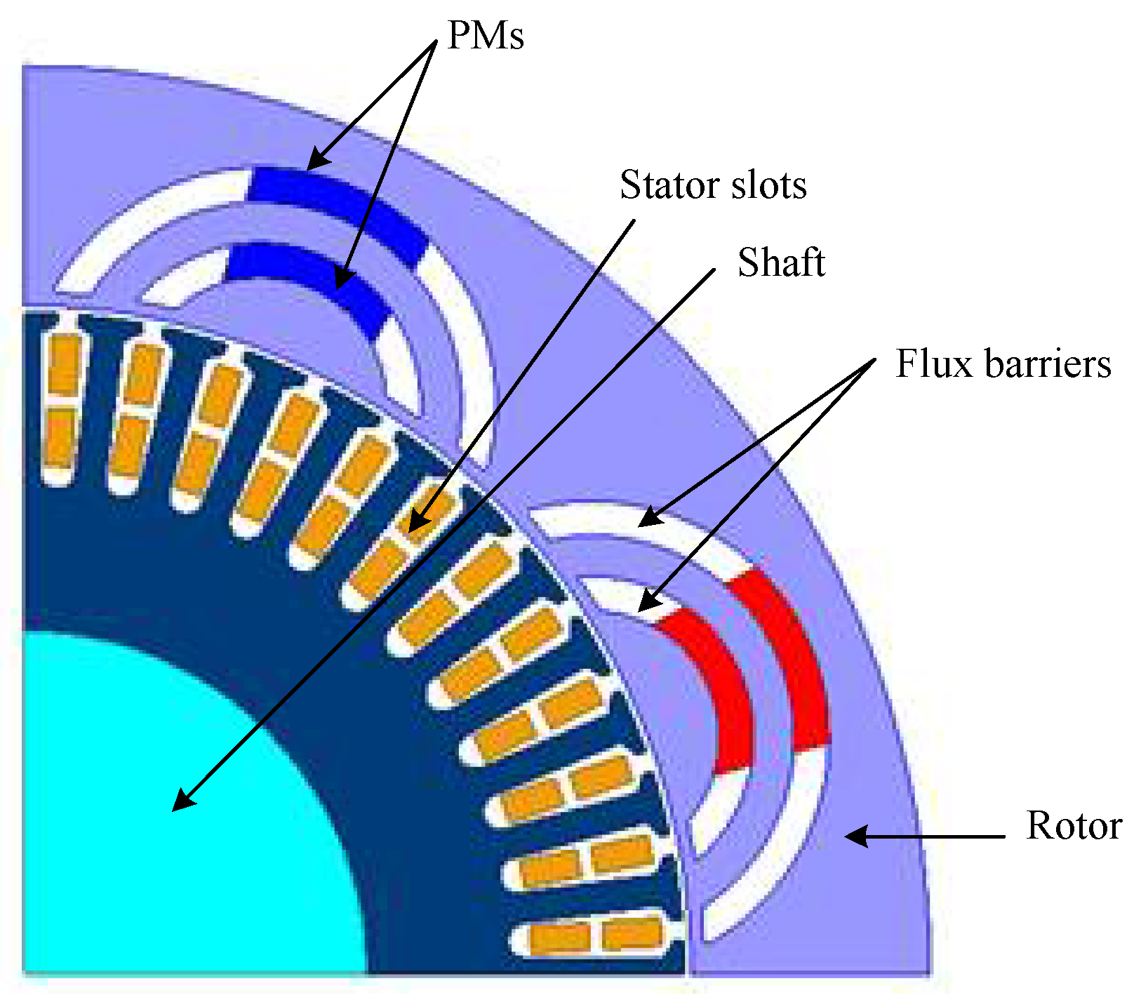
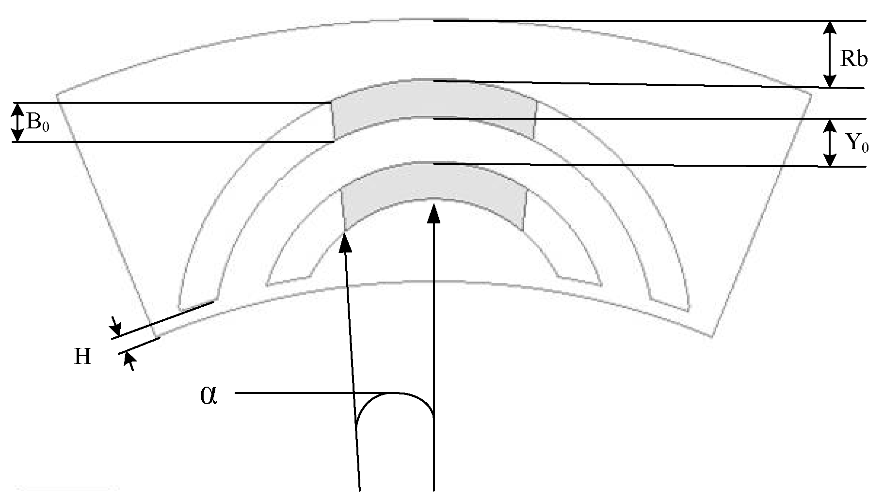
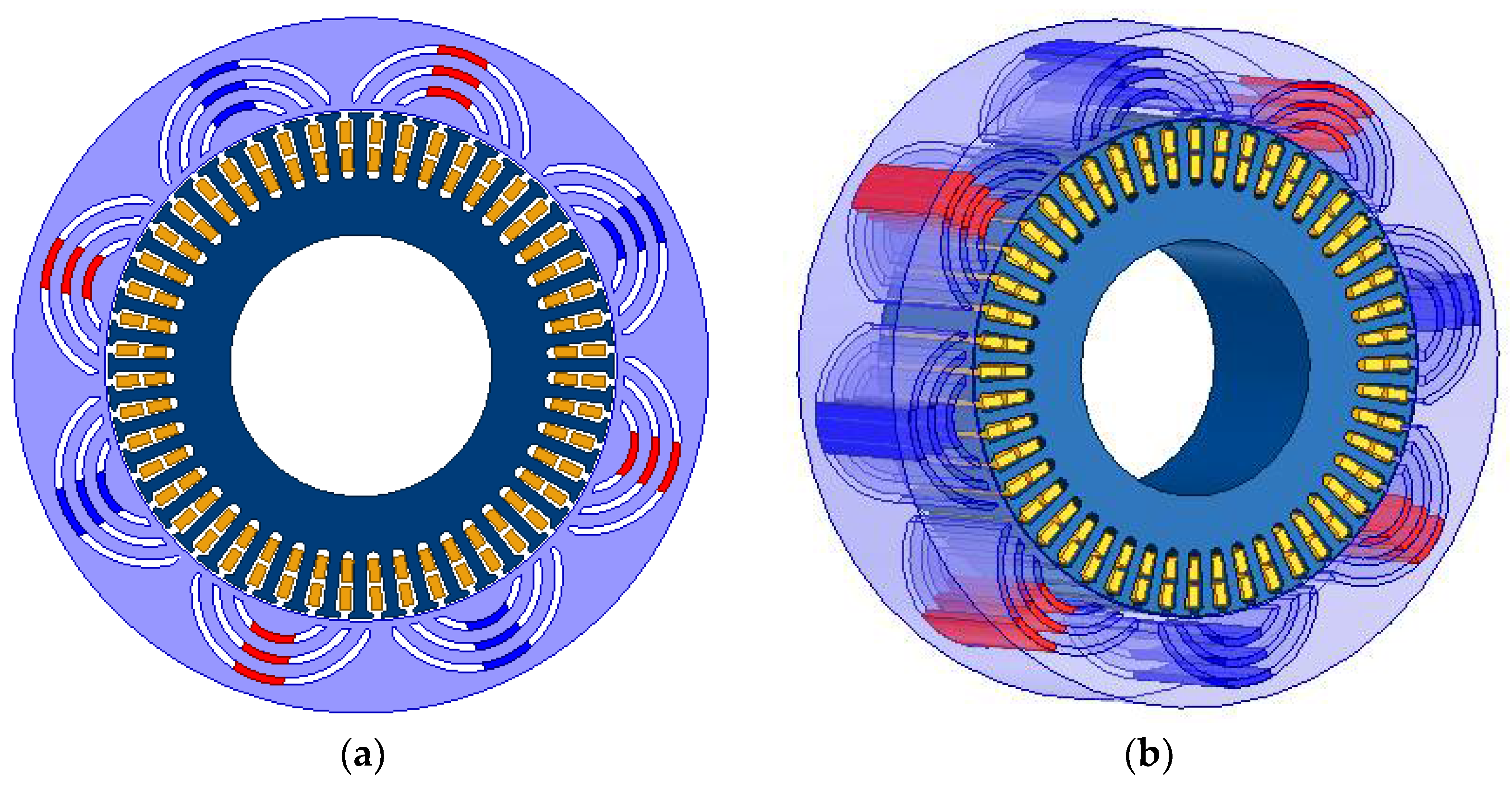
2. Design Process
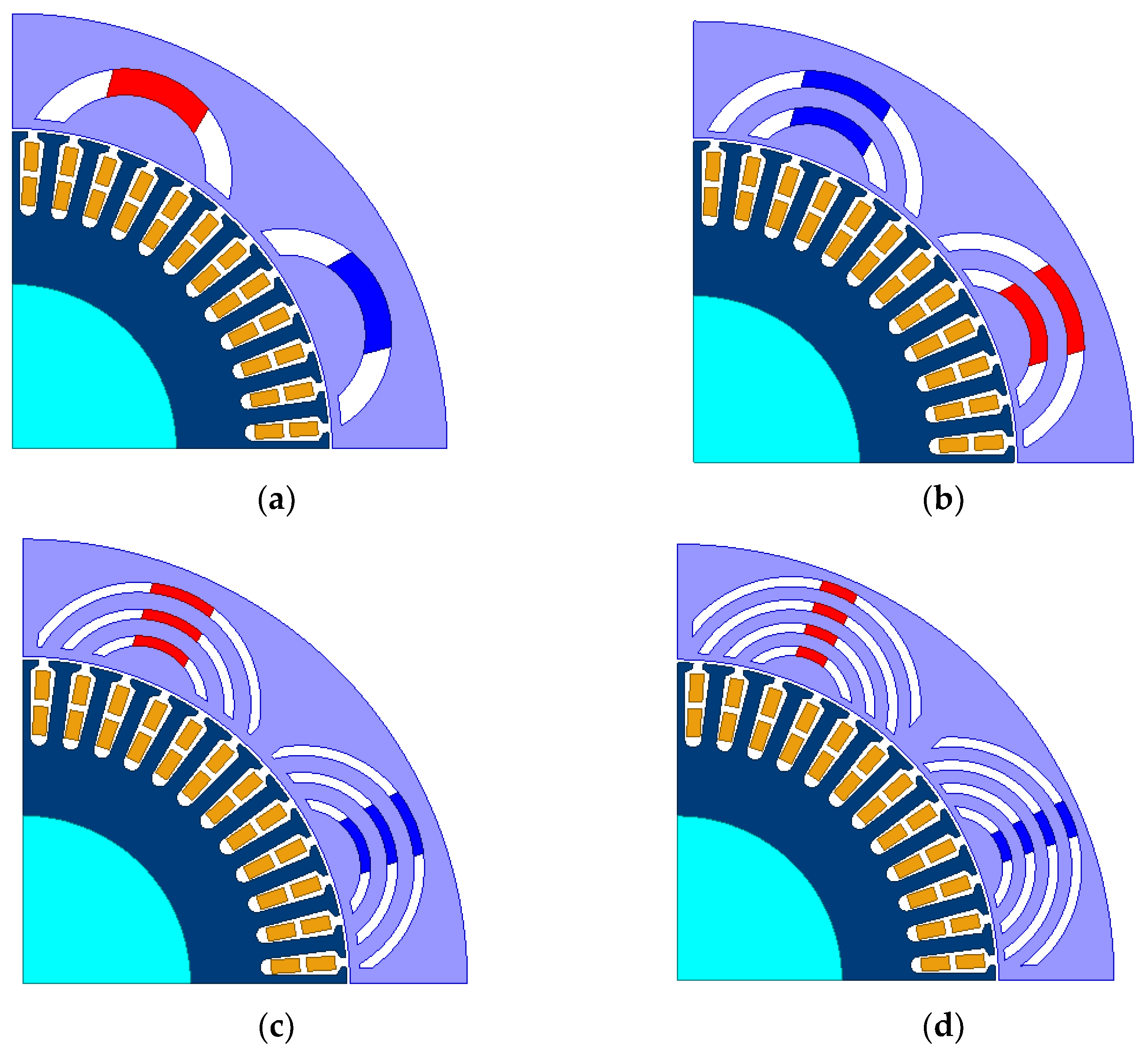
2.1. Improvement
2.2. Efficiency
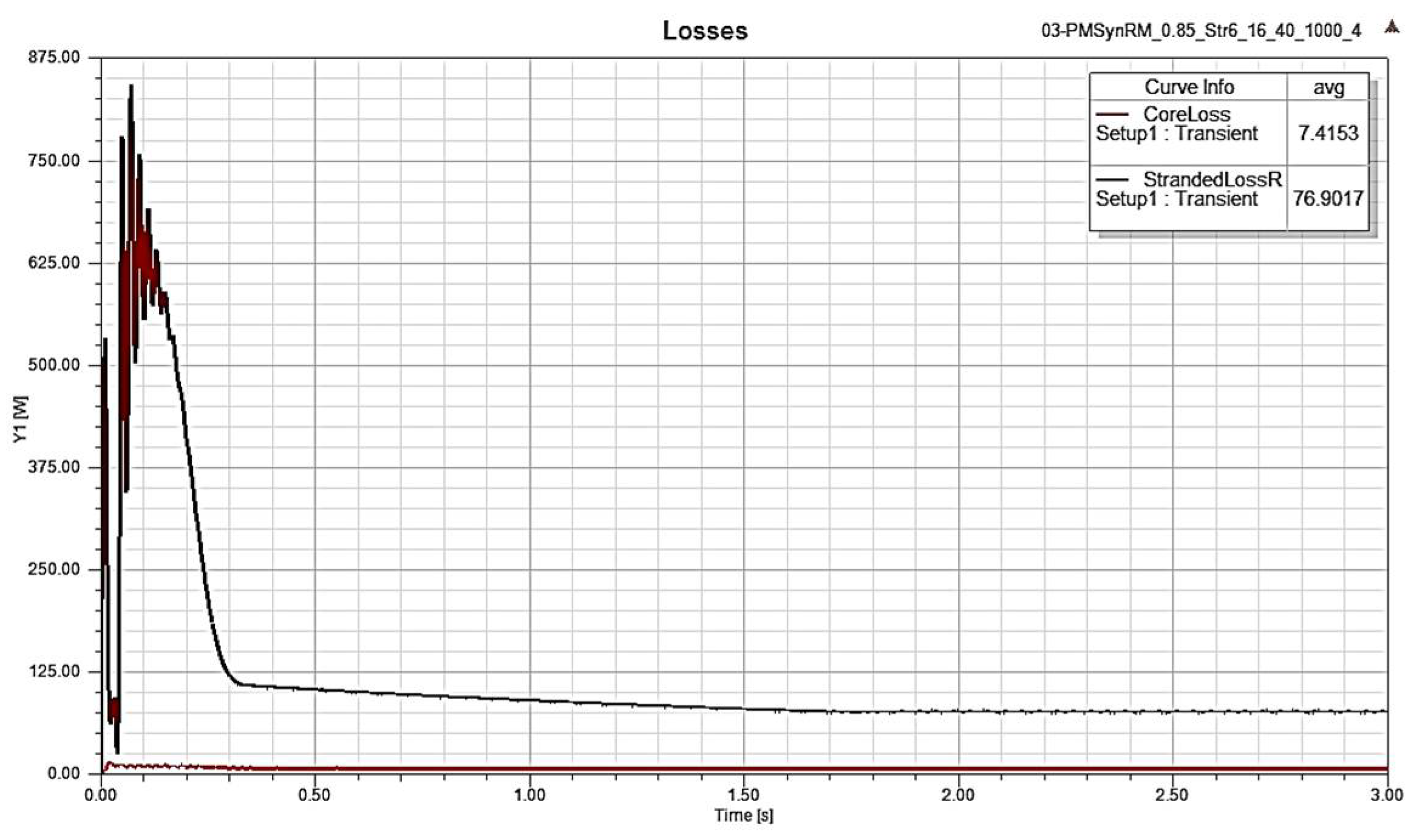
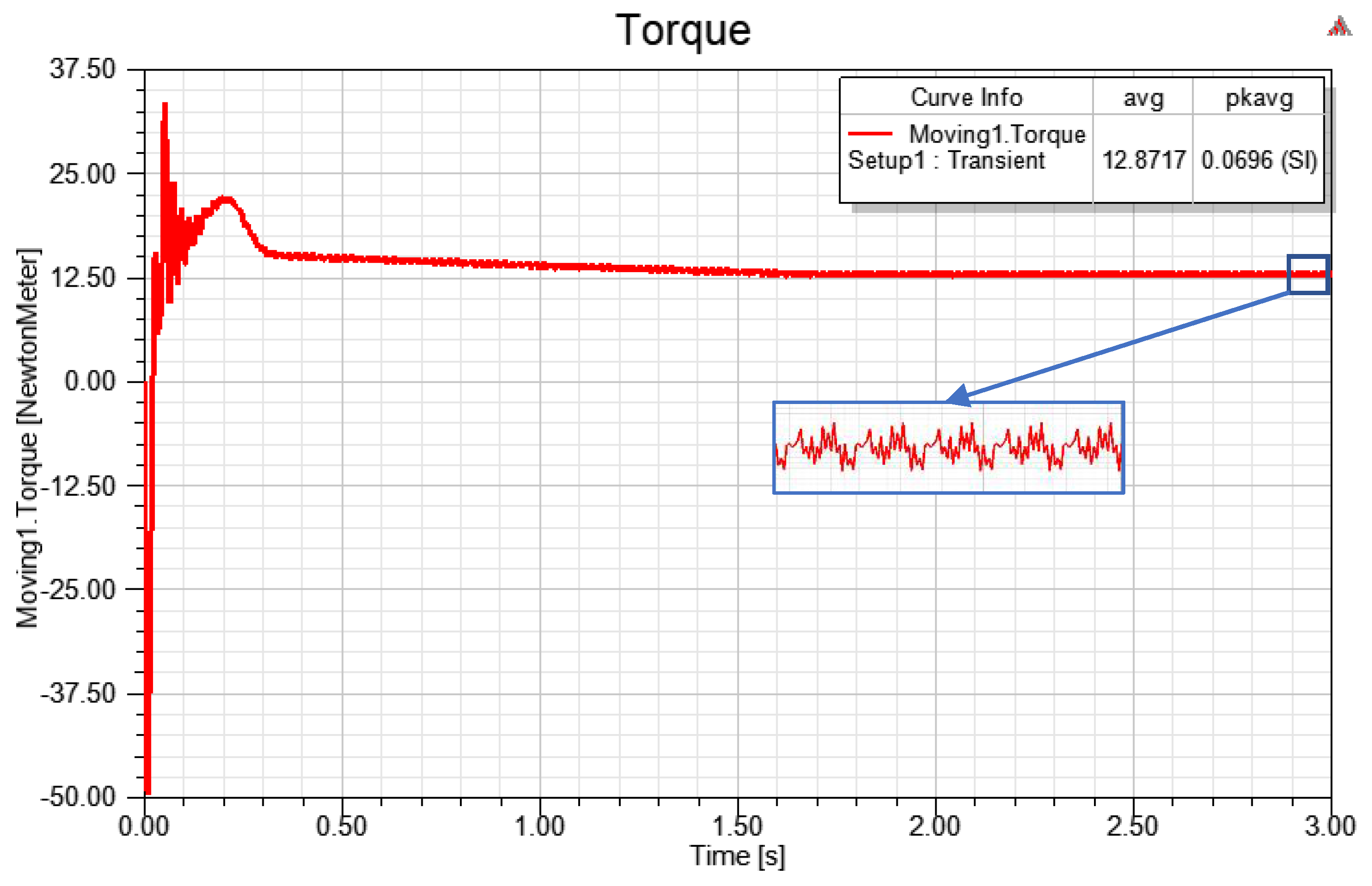
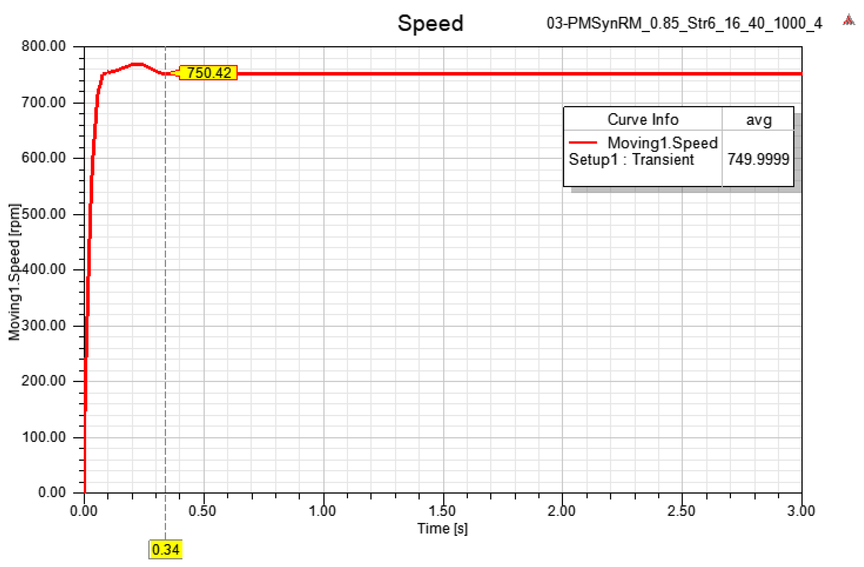
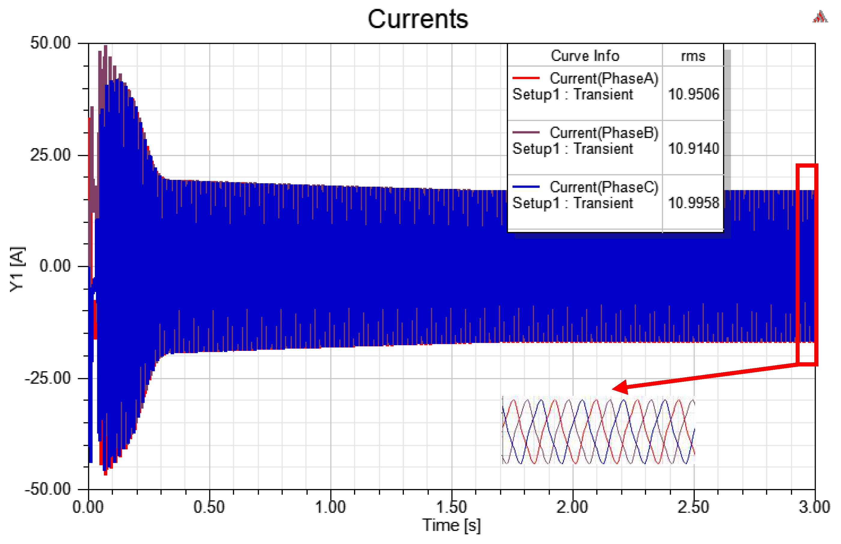
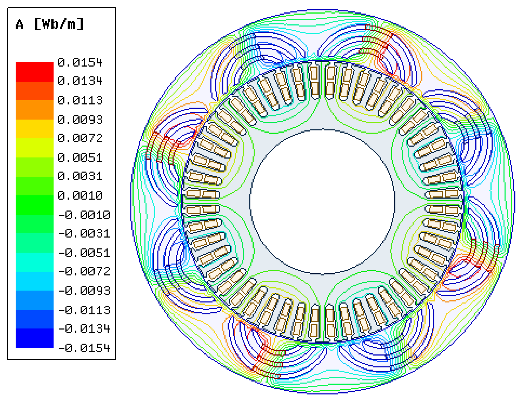
3. Simulation Results
4. Conclusions
Author Contributions
Funding
Conflicts of Interest
References
- Tumbek, M.; Kesler, S. Design and Implementation of a Low Power Outer-Rotor Line-Start Permanent-Magnet Synchronous Motor for Ultra-light Electric Vehicles. Energies 2019, 12, 3174. [Google Scholar] [CrossRef] [Green Version]
- Moradi CheshmehBeigi, H.; Behroozi, L. Analytical Design, Electromagnetic Field Analysis and Parametric Sensitivity Analysis of An External Rotor Permanent Magnet-Assisted Synchronous Reluctance Motor. Electr. Eng. 2020, 102, 1947–1957. [Google Scholar] [CrossRef]
- Guan, Y.; Zhu, Z.Q.; Afinowi, I.A.A.; Mipo, J.C.; Farah, P. Design of Synchronous Reluctance and Permanent Magnet Synchronous Reluctance Machines for Electric Vehicle Application. Int. J. Comput. Math. Electr. Electron. Eng. 2016, 35, 586–606. [Google Scholar] [CrossRef]
- Bonthu, S.S.R.; Islam, M.Z.; Arafat, A.; Choi, S. Five-Phase External Rotor Permanent Magnet Assisted Synchronous Reluctance Motor for In-Wheel Applications. In Proceedings of the 2017 IEEE Transportation Electrification Conference and Expo (ITEC), Chicago, IL, USA, 22–24 June 2017; pp. 586–591. [Google Scholar]
- Huynh, T.A.; Hsieh, M.-F. Performance Analysis of Permanent Magnet Motors for Electric Vehicles (EV) Traction Considering Driving Cycles. Energies 2018, 11, 1385. [Google Scholar] [CrossRef] [Green Version]
- Wu, W.; Zhu, X.; Quan, L.; Du, Y.; Xiang, Z.; Zhu, X. Design and Analysis of a Hybrid Permanent Magnet Assisted Synchronous Reluctance Motor Considering Magnetic Saliency and PM Usage. IEEE Trans. Appl. Supercond. 2018, 28, 1–6. [Google Scholar] [CrossRef]
- Zeraouila, M.; Benbouzid, M.E.H.; Diallo, D. Electric Motor Drive Selection Issues for HEV Propulsion Systems: A Comparative Study. In Proceedings of the IEEE Vehicle Power and Propulsion Conference, Chicago, IL, USA, 7–9 September 2005; pp. 280–287. [Google Scholar]
- Anekunu, A.Y.; Chowdhury, S.P.; Chowdhury, S. A Review of Research and Development on Switched Reluctance Motor for Electric Vehicles. In Proceedings of the IEEE Power & Energy Society General Meeting, Vancouver, BC, Canada, 21–25 July 2013; pp. 1–5. [Google Scholar]
- Goncalves, A.P.; Cruz, S.M.A.; Ferreira, F.J.T.E.; Mendes, A.M.S.; De Almeida, A.T. Synchronous Reluctance Motor Drive for Electric Vehicles Including Cross-Magnetic Saturation. In Proceedings of the IEEE Vehicle Power and Propulsion Conference (VPPC), Coimbra, Portugal, 27–30 October 2014; pp. 1–6. [Google Scholar]
- Ibrahim, M.N.F.; Rashad, E.; Sergeant, P. Performance Comparison of Conventional Synchronous Reluctance Machines and PM-Assisted Types with Combined Star-Delta Winding. Energies 2017, 10, 1500. [Google Scholar] [CrossRef]
- Morimoto, S.; Ooi, S.; Inoue, Y.; Sanada, M. Experimental Evaluation of a Rare-Earth-Free PMASynRM with Ferrite Magnets for Automotive Applications. IEEE Trans. Ind. Electron. 2014, 61, 5749–5756. [Google Scholar] [CrossRef]
- Ashkezari, J.D.; Khajeroshanaee, H.; Niasati, M.; Mojibian, M.J. Optimum Design and Operation Analysis of Permanent Magnet-Assisted Synchronous Reluctance Motor. Turk. J. Electr. Eng. Comput. Sci. 2017, 25, 1894–1907. [Google Scholar] [CrossRef]
- Liu, C.-T.; Luo, T.-Y.; Shih, P.-C.; Yen, S.-C.; Lin, H.-N.; Hsu, Y.-W.; Hwang, C.-C. On the Design and Construction Assessments of a Permanent-Magnet-Assisted Synchronous Reluctance Motor. IEEE Trans. Magn. 2017, 53, 1–4. [Google Scholar]
- Aghazadeh, H.; Afjei, E.; Siadatan, A. Comprehensive Design Procedure and Manufacturing of Permanent Magnet Assisted Synchronous Reluctance Motor. Int. J. Eng. 2019, 32, 1299–1305. [Google Scholar]
- Mohammadi, A.; Mirimani, S.M. Design and Analysis of a Novel Permanent Magnet Assisted Synchronous Reluctance Machine Using Finite-Element-Method. In Proceedings of the 11th Power Electronics, Drive Systems, and Technologies Conference (PEDSTC), Tehran, Iran, 4–6 February 2020; pp. 1–5. [Google Scholar]
- Bonthu, S.S.R.; Islam, M.Z.; Choi, S. Design of A Rare Earth Free External Rotor Permanent Magnet Assisted Synchornous Reluctance Motor. In Proceedings of the IEEE International Electric Machines and Drives Conference (IEMDC), Miami, FL, USA, 21–24 May 2017; pp. 1–6. [Google Scholar]
- Bianchi, N.; Bolognani, S.; Carraro, E.; Castiello, M.; Fornasiero, E. Electric Vehicle Traction Based on Synchronous Reluctance Motors. IEEE Trans. Ind. Appl. 2016, 52, 4762–4769. [Google Scholar] [CrossRef]
- Islam, M.Z.; Choi, S.; Elbuluk, M.E.; Bonthu, S.S.R.; Arafat, A.; Baek, J. Design of External Rotor Ferrite-Assisted Synchronous Reluctance Motor for High Power Density. Appl. Sci. 2021, 11, 3102. [Google Scholar] [CrossRef]
- Bonthu, S.S.R.; Choi, S.; Gorgani, A.; Jang, K. Design of Permanent Magnet Assisted Synchronous Reluctance Motor with External Rotor Architecture. In Proceedings of the IEEE International Electric Machines & Drives Conference (IEMDC), Coeur d’Alene, ID, USA, 10–13 May 2015; pp. 220–226. [Google Scholar]
- EL-Refaie, A.M. Fractional-Slot Concentrated-Windings Synchronous Permanent Magnet Machines: Opportunities and Challenges. IEEE Trans. Ind. Electron. 2010, 57, 107–121. [Google Scholar] [CrossRef]
- Aghazadeh, H.; Afjei, S.E.; Siadatan, A. Sensitivity Analysis of External-Rotor Permanent Magnet Assisted Synchronous Reluctance Motor. World Acad. Sci. Eng. Technol. Int. J. Energy Power Eng. 2018, 12, 426–430. [Google Scholar]
- Zhu, X.; Shu, Z.; Quan, L.; Xiang, Z.; Pan, X. Multi-objective Optimization of an Outer-Rotor V-Shaped Permanent Magnet Flux Switching Motor Based on Multi-Level Design Method. IEEE Trans. Magn. 2016, 52, 1–8. [Google Scholar] [CrossRef]
- Nagarajan, V.S.; Kamaraj, V.; Sivaramakrishnan, S. Geometrical Sensitivity Analysis Based on Design Optimization and Multiphysics Analysis of PM Assisted Synchronous Reluctance Motor. Bull. Pol. Acad. Sci. Tech. Sci. 2019, 67. [Google Scholar] [CrossRef]
- Ersöz, M.; Öner, Y.; Bingöl, O. Akı Bariyerli TLA Tipi Senkron Motor Tasarımı ve Optimizasyonu. J. Fac. Eng. Archit. Gazi Univ. 2016, 31, 941–950. [Google Scholar]
- Wang, Y.; Ionel, D.M.; Rallabandi, V.; Jiang, M.; Stretz, S.J. Large-Scale Optimization of Synchronous Reluctance Machines Using CE-FEA and Differential Evolution. IEEE Trans. Ind. Appl. 2016, 52, 4699–4709. [Google Scholar] [CrossRef]


| Parameter | Value |
|---|---|
| Number of phases | 3 |
| Rated power (W) | 1000 |
| Rated torque (Nm) | 12.73 |
| Rated speed (rpm) | 750 |
| Rated current (rms) (A) | <13 |
| Slot/pole configuration | 48 slots and 8 poles |
| Rotor outer diameter (mm) | 265 |
| Stator outer diameter (mm) | 193 |
| Stack length (mm) | 80 |
| Air-gap length (mm) | 1 |
| Steel Material | M470-50A |
| Magnet Material | N35H |
| Frequency (Hz) | 50 |
| Phase Voltage (V) | 36 |
| Efficiency | >90% |
| Design Variables | Unit | Lower Bound | Upper Bound |
|---|---|---|---|
| α | degree | 16 | 20 |
| B0 | mm | 3 | 6 |
| Rb | mm | 3 | 7 |
| Y0 | mm | 2.5 | 5 |
| H | mm | 1.5 | 3 |
| Number of Barriers | Output Torque (Nm) | Torque Ripple |
|---|---|---|
| 1 barrier | 12.6467 | 22.93% |
| 2 barriers | 12.6446 | 12.88% |
| 3 barriers | 12.8717 | 6.96% |
| 4 barriers | 12.5851 | 9.01% |
| Speed (rpm) | 500 | 600 | 750 | 800 | 1000 | 1200 | 1500 |
| Tork (Nm) | 19.09 | 16.10 | 12.87 | 12.21 | 10.05 | 8.07 | 6.47 |
| Tork Ripple | 6.09% | 6.69% | 6.96% | 7.99% | 8.25% | 10.52% | 12.44% |
| Current (A) | 13.49 | 12.13 | 10.95 | 10.92 | 10.61 | 9.99 | 10.06 |
| Total Loss (W) | 137.42 | 115.11 | 96.32 | 94.74 | 90.76 | 81.74 | 82.38 |
| Output Power (W) | 999.25 | 1011.25 | 1010.87 | 1022.53 | 1052.35 | 1014.03 | 1016.15 |
| Input Power (W) | 1136.67 | 1126.36 | 1107.18 | 1117.27 | 1143.11 | 1095.77 | 1098.53 |
| Efficiency (%) | 87.91% | 89.78% | 91.30% | 91.52% | 92.06% | 92.54% | 92.50% |
Publisher’s Note: MDPI stays neutral with regard to jurisdictional claims in published maps and institutional affiliations. |
© 2021 by the authors. Licensee MDPI, Basel, Switzerland. This article is an open access article distributed under the terms and conditions of the Creative Commons Attribution (CC BY) license (https://creativecommons.org/licenses/by/4.0/).
Share and Cite
Bozkurt, A.; Baba, A.F.; Oner, Y. Design of Outer-Rotor Permanent-Magnet-Assisted Synchronous Reluctance Motor for Electric Vehicles. Energies 2021, 14, 3739. https://doi.org/10.3390/en14133739
Bozkurt A, Baba AF, Oner Y. Design of Outer-Rotor Permanent-Magnet-Assisted Synchronous Reluctance Motor for Electric Vehicles. Energies. 2021; 14(13):3739. https://doi.org/10.3390/en14133739
Chicago/Turabian StyleBozkurt, Armagan, Ahmet Fevzi Baba, and Yusuf Oner. 2021. "Design of Outer-Rotor Permanent-Magnet-Assisted Synchronous Reluctance Motor for Electric Vehicles" Energies 14, no. 13: 3739. https://doi.org/10.3390/en14133739
APA StyleBozkurt, A., Baba, A. F., & Oner, Y. (2021). Design of Outer-Rotor Permanent-Magnet-Assisted Synchronous Reluctance Motor for Electric Vehicles. Energies, 14(13), 3739. https://doi.org/10.3390/en14133739