Article

Multipulse Ballistic Injection: A Novel Method for Improving Low Temperature Combustion with Early Injection Timings

Department of Automotive Technology, Budapest University of Technology and Economics, H-1111 Budapest, Hungary
*
Author to whom correspondence should be addressed.
Energies 2021, 14(13), 3727; https://doi.org/10.3390/en14133727
Submission received: 23 April 2021 / Revised: 8 June 2021 / Accepted: 16 June 2021 / Published: 22 June 2021
(This article belongs to the Section I2: Energy and Combustion Science)

Abstract

:
Nowadays, increasingly stricter regulations on emission reduction are inducing rapid developments in combustion science. Low-temperature combustion (LTC) is an advanced combustion technology that increases an engine’s thermal efficiency and even provides low emissions of nitrogen oxides (NOx) and particulate matter (PM). The technology often uses early direct injections to achieve sufficient mixture homogeneity. This leads to increasing wall wetting and lower combustion efficiency. This paper introduces the Multipulse ballistic injection (MBI) method to improve combustion with early injection timings. The research was carried out in a four-cylinder medium-duty diesel engine with high-pressure exhaust gas recirculation (HP-EGR). The investigation was divided into two experiments. In the first experiment, MBI was examined without EGR, and in the second, EGR was applied to study its effects. It was found that the MBI strategy decreased wall wetting and increased homogeneity and the indicated mean effective pressure (IMEP) at early injection angles.

1. Introduction

1.1. The LTC Concept

Low-temperature combustion (LTC) is an advanced combustion concept that may contribute to meeting stringent emission legislations. The technology provides low fuel consumption and low pollutant emissions [1]. A further advantage is the fuel flexibility of the system, which enables the use of alternative fuels.
Various forms of application can achieve LTC, but the main concept is always the same. A highly homogeneous lean air–fuel mixture is prepared in the presence of a certain amount of residual gas, and then the charge is burned with auto-ignition. Due to mixture homogeneity, the local fuel-rich zones are reduced, which leads to a reduction in PM emission. The main source of NOx formation is the Zeldovich mechanism [2], which is highly dependent on temperature. Due to the application of the lean homogeneous mixture, the number of the local hotpoints are reduced, thus NOx emission decreases. The technology uses a non-negligible amount of residual gas in the combustion chamber. The combustion products have high heat capacity, therefore increasing the amount of residual gas leads to lower mean combustion temperature and lower NOx emission [3]. The LTC technology also provides high efficiency. LTC engines are quality controlled, thus throttling losses are eliminated. The lower temperature causes lower radiation loss. The amount of heat escaping with the exhaust gas is also lower due to the lower exhaust gas temperature [4]. These are the main reasons for high efficiency.
However, the LTC concept has many difficulties that prevent this technology from being used in the market. The combustion can only be controlled through indirect parameters, such as the physical and chemical properties of the air–fuel mixture, or the temperature–time history; therefore, control over the start of combustion and the combustion duration is difficult [5]. Due to the homogeneous charge, the ignition occurs at multiple points in the combustion chamber simultaneously. This rapid combustion leads to an unacceptably high pressure-gradient, which limits the operating range of the LTC [6]. The low temperature of the combustion can result in incomplete combustion, thus the CO and HC emissions increase. To achieve sufficient mixture homogeneity, LTC often uses early direct injection. This leads to increasing wall wetting; hence, HC emission also increases. This problem is much more marked when diesel fuel is used, because of its bad evaporation properties. External mixing devices can also be used to prepare the homogeneous mixture, but this is a more expensive method than direct injection. The LTC technology cannot be used in the market until these problems are solved.

1.2. The State-of-the-Art of LTC

The basic application of LTC is HCCI [7], where highly a homogeneous air–fuel mixture is used, with a high percentage of EGR. The EGR retards the start of combustion, prolongs the combustion, and reduces the combustion noise. However, HCCI shows most of the previously described problems. HECC is a special HCCI concept, where all emission can be kept low, but its applicability is low [8]. PCCI, PPCI, PPC and some other methods use premixed, or partially premixed mixtures to overcome the LTC issues [9]. Some techniques, e.g., SPCCI, use spark ignition to trigger the autoignition at the proper time [10]. The properties of the charge can also be stratified to prolong the combustion. RCCI uses reactivity stratification [11] and TSCI uses thermal stratification [12].
The described methods provide a good solution for combustion control and noise reduction, and they also help to expand the operating range of LTC. However, the often-used early direct injection leads to wall wetting and high HC emission. The state-of-the-art solutions for this problem are the narrow cone angle injectors [13], that can help to reduce wall impingement. Another approach is MK combustion [14], which uses late direct injection with enlarged ignition delay. In-cylinder catalysts can also be used to help the oxidation near the wall [15]. In this paper we investigate a new method named Multipulse ballistic injection (MBI), which improves the combustion when early direct injection is used. The MBI helps to avoid wall impingement and increases mixture homogeneity.

1.3. State-of-the-Art Multipulse Injection Strategies

The most common conventional multipulse strategies are split injection and pilot injection. Split injection uses two injections of the same amount, while pilot injection uses one main injection and several pre- (and sometimes post-) injections [16]. Here, the purpose of the multiple injection is to split the heat release, to control the fuel distribution, and to take advantage of the cooling effect of fuel vaporization. The heat-release split decreases the peak heat release and the combustion noise. The fuel distribution control reduces the soot emission due to the better air usage. The cooling effect of fuel vaporization can be used to increase the ignition delay [17]. The post-injections can manage the exhaust aftertreatment, and reduce the engine-out emission. The post-injection enhances mixing and increases temperature; therefore, the oxidation is better. It also helps with heating up the catalysts to the operating temperature [18].
Other approaches are digital combustion rate shaping (DiCoRS) and continuous combustion rate shaping (CoCoRS). Each method manipulates the fuel injection profile to control the heat release rate, the combustion noise, and the engine-out emission. CoCoRS controls the fuel mass flow continuously, thereby this method can control the combustion precisely. However, a special injector is needed that is capable of realizing this strategy. DiCoRS uses multiple fuel shots to create a digital dose profile that follows the necessary continuous profile [19]. This multipulse strategy uses multiple injections with different injection durations. Some of these injections can be so short that they are in the ballistic region, but here the focus is on the combustion shaping.
When applying a highly homogeneous mixture, the fuel injection strategy cannot influence the combustion rate. LTC technologies often use early direct injection to achieve sufficient mixture homogeneity, but this leads to wall impingement and unacceptably high HC emission. Another problem of the direct injection is that it hardly creates a high enough degree of homogeneity. The presented MBI method provides a good solution for these problems.

1.4. The Applied MBI Strategy

The main purpose of the presented work is to achieve better combustion at early injection angles. To achieve this goal, Multipulse ballistic injection is introduced. The MBI is a new special multipulse injection strategy, whereby the injector operates in its ballistic region, and a high number of injections are required to bring the necessary dose into the cylinder. When operating a solenoid injector, the valve needs time to fully open. If the injection duration is so short that the coil energizing ends before the needle reaches its final position, then the injection is called ballistic [20]. The state-of-the-art multipulse injection methods are not focusing specially on this ballistic region.
The MBI is based on two main hypotheses. It is presumed that the momentum of the fuel-spray droplets is less when operating the injector in ballistic mode, thus wall impingement decreases. A further assumption is that multiple small injections create multiple small fuel-sprays with larger surface than a single fuel-spray. This results in better evaporation and mixing; hence homogeneity increases.
To achieve MBI, the injections must be short and close-coupled. The lower limit of the injection duration is 200 μs, which is provided by the measurement system. Results showed that a 500 μs threshold time must be applied after deenergizing the coil to realize different injection events. However, close-coupled injections can still have some instability due to hydraulic interactions, unrecovered deformations, and other changes in boundary conditions [21].
Studying the injector characteristics on Figure 1, a break can be seen at 0.3 ms. This means that the 0.2 ms and the 0.3 ms injection durations are in the ballistic range of the injector. Figure 2 shows an MBI case with 15 injections, and a single injection case. These are comparable measurements because the injection structures have a common center of injection (CoI) and dose.

2. Experimental Apparatus and Methods

2.1. Experimental Engine and Apparatus

The experiment was carried out in a cylinder of a modified Cummins ISBe 170 30 engine. It is a turbocharged, medium-duty commercial diesel engine with a common-rail injection system. The Euro 3 level engine is equipped with an intercooler, and a high-pressure EGR system. The engine was installed on an engine dynamometer in which all the necessary operating parameters were measurable. The main engine parameters of the engine are given in Table 1.
The injector of the fourth cylinder is controlled with a dSpace MicroAutobox DS1401/1505/1506 and a single RapidPro Power Unit. The control algorithm is implemented in a Matlab-Simulink environment and the system can be controlled with dSpace ControlDesk. The power unit’s PS-DINJ2/1 module is used as a power stage, which is designed to drive inductive loads, such as electromagnetic injection valves. Owing to the fact that the injector demands a high-amplitude pulsating drive current, proper shielding is required to avoid unwanted electromagnetic noise.
The injected fuel dose is estimated with an injector model simulated in a GT-SUITE environment. The model requires the injector current and the rail-pressure characteristics as an input. The model is validated with gravimetric fuel measurements [22].
The cylinder pressure was measured with an AVL GH13P piezoelectric sensor, which is connected to the seat of the glow-plug. To measure the crank angle position, an AVL 365C crank angle encoder was used with a resolution of 0.5 °CA. The combustion analysis was carried out with an AVL 612 Indi-Smart.
The nitrogen oxide concentration was measured with a UniNOx-Sensor and the PM emission was measured with an AVL 439 Opacimeter.

2.2. Experimental Methods

The investigation is divided into two experiments. In the first experiment, five different injection structures with the same 27 mg dose are applied without EGR. Here the goal is to study the effects of the injection decomposition to confirm that MBI reduces wall wetting, and increases homogeneity. Each statement will be proven indirectly with combustion analysis. The absence of EGR in the first experiment requires low load conditions to avoid dangerous levels of knocking. The applied load is 50 Nm at 1250 rpm. The investigated cases of the first experiment can be seen in Table 2.
The second experiment’s goal is to determine the applicability of the MBI method. The EGR is a key component for real LTC applications, thus the second experiment investigates the EGR’s effect on the combustion while using MBI strategy. The applied load is 50 Nm at 1250 rpm. Due to changed measurement conditions a 0.2 ms × 11 injection structure with 31 mg dose is used. Five different EGR rates are applied with the HP-EGR system. The investigated cases of the second experiment can be seen in Table 3.
The research has three variables: dose decomposition, injection angle, and EGR rate. The injected dose remains constant during an experiment, but depending on the chosen decomposition rate, it can be introduced into the cylinder with different number of injections. Several numbers of injections are investigated between 1 and 15.
The highly decomposed MBI cases need more time to inject the same dose than a single injection. To make these cases comparable, the injection angle is described with the center of injection, which is the average of the start and end angle of the injection. This CoI parameter is studied between 50 °CA and 365 °CA. In this article 0 °CA means the TDC of gas exchange.
The EGR rate is varied between 0% and 72%, and it is calculated with the formula below:
E G R = O 2   i n O 2   a m b O 2   o u t O 2   a m b 100 %
The two experiments are divided into several series of measurements, which consist of multiple measurement points. All variables of the measurement points are fixed, and the presented results are derived from the average of many cycles. A series of measurements consist of 64 measurement points with different CoIs between 50 °CA and 365 °CA with a resolution of 5 °CA. The resulted combustion parameters can be represented in the function of CoI by plotting a set of measurements. Each experiment compares five series of measurements.

3. Results and Discussion

3.1. First Experiment

In these series of measurements, the effects of MBI are investigated without EGR. The goal is to detect the signs of reduced wall wetting, increased homogeneity, and other changed conditions.
Figure 3 shows IMEP, and Figure 4 shows the released heat as a function of CoI. The maxima of the curves are close to TDCF. Advanced injections decreased the heat release, which suggests increased wall impingement at early CoIs. IMEP depends on heat release; therefore, it is also lessened. Investigating the heat release curves, it is clearly visible that green and the purple MBI curves are much higher than the blue single injection curve, even at CoIs close to TDCF. Considering that the dose was the same in all cases, the grown heat release indicates better combustion conditions. The difference between the MBI and the single injection is the strongest at early injections, but a rise in the IMEP and the heat release can also be observed close to TDCF. An obvious explanation for this phenomenon is the enhanced homogeneity of the mixture because the effect of wall impingement is negligible near TDCF. In the case of the early injections the wall wetting also influences the heat release. The increased maximum IMEP raised the maximum calculated indicated thermal efficiency from 37% to 46%.
Improved air–fuel mixing increases the heat release at every injection timing, but wall wetting’s detrimental impacts emerge only at early injections. To determine whether wall impingement is reduced, comparison with the absolute heat release values is unenlightening. Instead of this, the heat release values compared to the maxima of the heat release curves are investigated. Figure 5 shows the heat release curves divided by the maxima of each curve as a percentage.
The specified curves show the extent to which the heat release changed depending on CoI. If a data point is higher at an early CoI, it means that the heat release’s diminution is less in that case. The main reason for lower heat release due to insufficient burning at early injection timings is wall impingement; therefore, higher specific curves mean lesser wall wetting. The differences between the MBI and the single injection are clear. The MBI curve’s minimum value is around 58%, while the single injection curve’s minimum is around 18%. This big difference is a clear evidence of minor wall wetting with MBI.
Another influencing parameter of IMEP is the center of heat release, which must be close to TDCF to avoid high compression work or worsening burning conditions at the expansion stroke. Figure 6 shows the center of heat release as a function of CoI. It can be observed that before 330 °CA, the MBI has earlier centers of heat releases, which imply improved burning conditions—this supports the claim of enhanced air–fuel mixing. After 330 °CA the tendency changes and the MBI has later centers of heat releases. The reason for this trend is that MBI’s injection duration is much longer than a single injection. The 0.2 ms × 15 structure had 90 °CA injection duration in our experiment. Hence, the MBIs with CoIs close to TDCF hang into the combustion, and a prolonged heat release with later centers of heat release occurs. This late center of heat release generates a notable reduction in IMEP, which can be seen in Figure 3.
Figure 7 shows the maxima of pressure gradients as a function of CoI. Note that in the first experiment EGR was not applied. It is discernible that before 320 °CA the pressure gradient maxima of the MBI cases are higher. The values of these maxima are higher and more advanced with increasing decomposition. This also substantiates the superior burning conditions and air–fuel mixing of MBI. It can be also observed that with injection timings close to TDCF the maximum rate of pressure rise is lower in the case of MBI. The reason for this trend is the prolonged heat release described earlier. This phenomenon is similar to the heat release split effect of the conventional split injection strategies.
Figure 8 shows the maxima of temperatures as a function of CoI. The cycles’ temperature characteristics were calculated from the pressure data with the general gas equation. The nature of the curves is similar to Figure 7. Improving burning conditions with increasing decomposition induces higher temperature maxima.
Figure 9 shows the NOx emission as a function of CoI. Note that the test engine is an out-of-date model. However, the results presented in this paper are still appropriate to observe the properties and trends of MBI. It can be seen that MBI produces higher NOx emissions between 240 °CA and 300 °CA CoI. If we check Figure 7, before 300 °CA the temperature maxima are higher in the case of MBI. Hence the temperature-dependent Zeldovich mechanism is a main source of NOx production, and the higher temperature results in higher NOx emission. However, before 240 °CA the tendency changes and NOx emission decreases. Here the temperature is lower than 1800 K; therefore, the NOx generated by the Zeldovich mechanism is lower. Thus, the ratio of prompt NO compared to the complete NOx emission is higher in this region. The generation of prompt NO depends on the local equivalence ratio. Owing to the fact that multipulse injection has a superior air–fuel mixing property, and the charge has fewer local rich zones, it is conceivable that the reduction in prompt NO causes the lower NOx emissions in that region. A further possible reason is that the better temperature homogeneity of MBI reduces the number of local hotspots.
Figure 10 shows the PM emission as a function of CoI. The curves can be divided into three parts. The first part refers to the CoIs above 320 °CA and it shows the negative effects of MBI’s long injection duration. The middle part refers to the CoIs between 280 °CA and 320 °CA and it shows the benefits of using MBI. The last part refers to the CoIs under 280 °CA, and it shows the MBI’s better burning conditions at really early injection timings. To understand the resulted characteristics of the three parts, the heat release rate and the accumulated heat release must be investigated in parallel.
At the first part, the PM emission of the MBI is higher than the single injection. The 0.2 ms × 15 structure has a 90 °CA injection duration; therefore, at CoIs close to TDCF, most of the fuel is injected during combustion. In this case, the injected fuel has no time to mix with the air; it burns immediately with diffusion flame and local rich regions to generate a high amount of soot. This assertion is supported by the heat release rates. Figure 11 shows the heat release rates at 355 °CA CoI. The fuel injected by the single injection burns in a similar way to conventional diesel combustion. After a short, premixed flame comes a diffusion flame. In the case of the MBI, the combustion starts earlier and after a premixed phase there is a long diffusion flame phase. The accumulated heat release curves shown in Figure 12 are more enlightening. A slow, nearly linear heat release can be observed with the 0.2 ms × 15 structure, which lasts approximately until the end of injection at 400 °CA.
At the last parts of the curves, the MBI’s PM emission is also much higher than the single injection’s emission. Here the injections happen too early, thus wall wetting enhances. A rise in PM emission can be seen at all of the curves while advancing the injection timings. This rise can be related to the increased wall impingement. Further advancing results lower PM emissions at all of the curves, despite that the wall wetting should be worsening. The answer for this phenomenon is provided again by the heat release rates. Figure 13 shows the heat release rates at 200 °CA CoI. It can be observed that the combustion of the single injection is really weak, which is the result of the worsening burning conditions. This weak combustion could not produce a high amount of soot. However, the MBI’s combustion is still robust, thus soot can easily be formed. The fact that the heat release of MBI is much higher than that of single injection at really early CoIs also supports the claim that MBI has lesser wall impingement.
At the middle parts of the PM curves it is discernible that the MBI’s PM emission is lower than the single injection’s. Here the injections take place far enough from TDCF to avoid big overlaps with combustion; therefore, the MBI’s soot formation from diffusion flame is avoided. The middle part has early injection timings, but not so early as to increase the PM emission—the negative effects of wall wetting can be avoided here. This part is also indirect evidence for the better burning conditions of MBI at early injection angles.
In conclusion, the presented results, including the soot diagram and the heat release curves, show that MBI improves homogeneity and reduces wall wetting even at extreme early injection angles. However, the extreme early injection angles are still of interest, since wall wetting is still present in this case.

3.2. Second Experiment

In the second experiment the EGR’s effect on the MBI is investigated in order to determine the applicability of the MBI method.
Figure 14 shows IMEP and Figure 15 shows the released heat as a function of CoI with the 0.2 ms × 11 MBI structure at different EGR rates. Each diagram has the same characteristics. The EGR has a dilution effect—the oxygen concentration is decreasing with increasing EGR rate. The 72% EGR is so high that the mixture is not burning in the case of early CoIs. After 300 °CA CoIs, the increasing EGR rate reduces the IMEP and the heat release. In these cases, a part of the injection hangs into the combustion, which results a diffusion flame. A portion of the mixture is not homogeneous in a diffusion flame, so the reduced oxygen concentration decreases the released heat. Before 300 °CA the applied lean mixture is completely homogeneous; therefore, the reduced oxygen concentration has no detrimental impact on the heat release. Before 300 °CA the 60% EGR rate has the highest IMEP. The reason for this trend is the EGR’s influence on the center of heat release. The EGR’s high heat capacity lowers the combustion temperature and retards the start of combustion, while the chemical effect of the EGR prolongs the heat release; therefore, the center of heat release retards. Early CoIs result in an early center of heat release, which leads to increased compression work and efficiency loss, so retarding the start of combustion improves the efficiency. The center of heat release needs to be around TDCF to achieve the best efficiency [23] and according to Figure 16, the 60% EGR rate fulfills this requirement. The 72% EGR rate has high cyclic variability, thus its presented center of heat release curve is not stable.
Figure 17 shows the EGR’s influence on the pressure gradient. The retarded start of combustion and the prolonged combustion results in lower pressure gradient maxima. The maximum accepted rate of pressure rise is 10 bar/°CA, [24,25]. The cooling effect of the EGR can also be observed on Figure 18. The lower temperature results lower NOx emission, because the Zeldovich mechanism depends on temperature. The NOx emission is presented on Figure 19. However, the increasing EGR rate increases the number of local rich zones, thus the PM emission presented in Figure 20 increases.

3.3. The Applicability of MBI

According to the first experiment, the MBI effectively reduces wall wetting and improves air–fuel mixing. However, CoIs earlier than 300 °CA are still unusable, since wall wetting cannot be completely eliminated, and they result in low IMEP. The improved mixing conditions increased the rate of pressure rise and the temperature, thus EGR must be applied. The advanced centers of heat releases of the early injections also require the use of EGR. The EGR rate has an upper limit, where misfire and cyclic variability occurs. In the second experiment, the highest EGR rate with stable operation was 60%. NOx emission can be decreased by EGR, but it raises PM emission, so a compromise is needed. The MBI’s injection duration is long; therefore, the injection hangs into the combustion in the case of late CoIs. This results in a diffusion flame, which increases PM emission. In our experiment the best compromise is the 0.2 ms × 11 MBI structure with 34% EGR rate at 330 °CA CoI, because it has acceptable heat release and rate of pressure rise, and the emissions are also compromised. However, the applied Euro 3 test engine is not suitable to achieve outstanding emission results, so the MBI will have to be tested in a state-of-art engine as well.
The main disadvantage of the MBI method is the long injection duration. The highest IMEP occurs at CoIs close to TDCF, but the increasing PM emission due to the long injection prevents the usage of this region. To get rid of this problem, future investigations have to focus on Continuous ballistic injection (CBI). The CBI method uses only one long ballistic injection. This eliminates the threshold times between the injections, so CBI’s injection duration is shorter than MBI’s, but it may keep the advantages of the ballistic operation mode.

4. Conclusions

The effects of Multipulse ballistic injection strategy were investigated with and without EGR. The measurements revealed that MBI is able to reduce wall impingement and improve air–fuel mixing. However, some further improvement is required to achieve applicability.
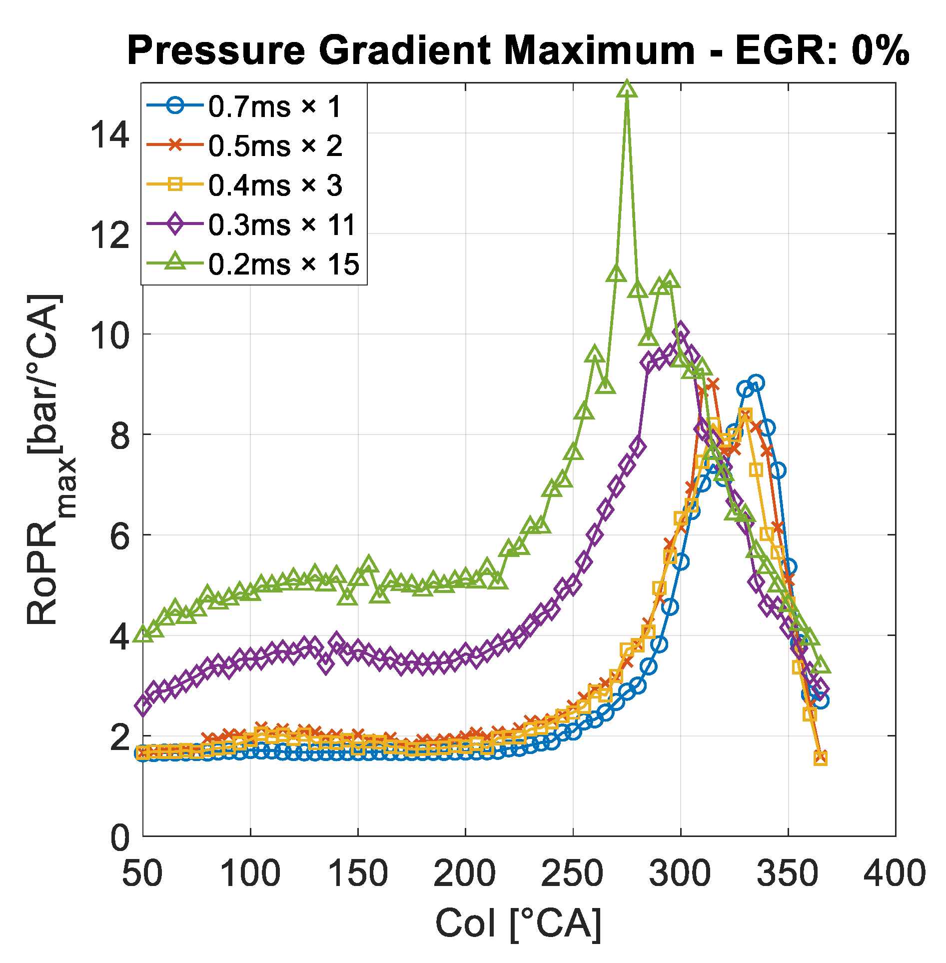
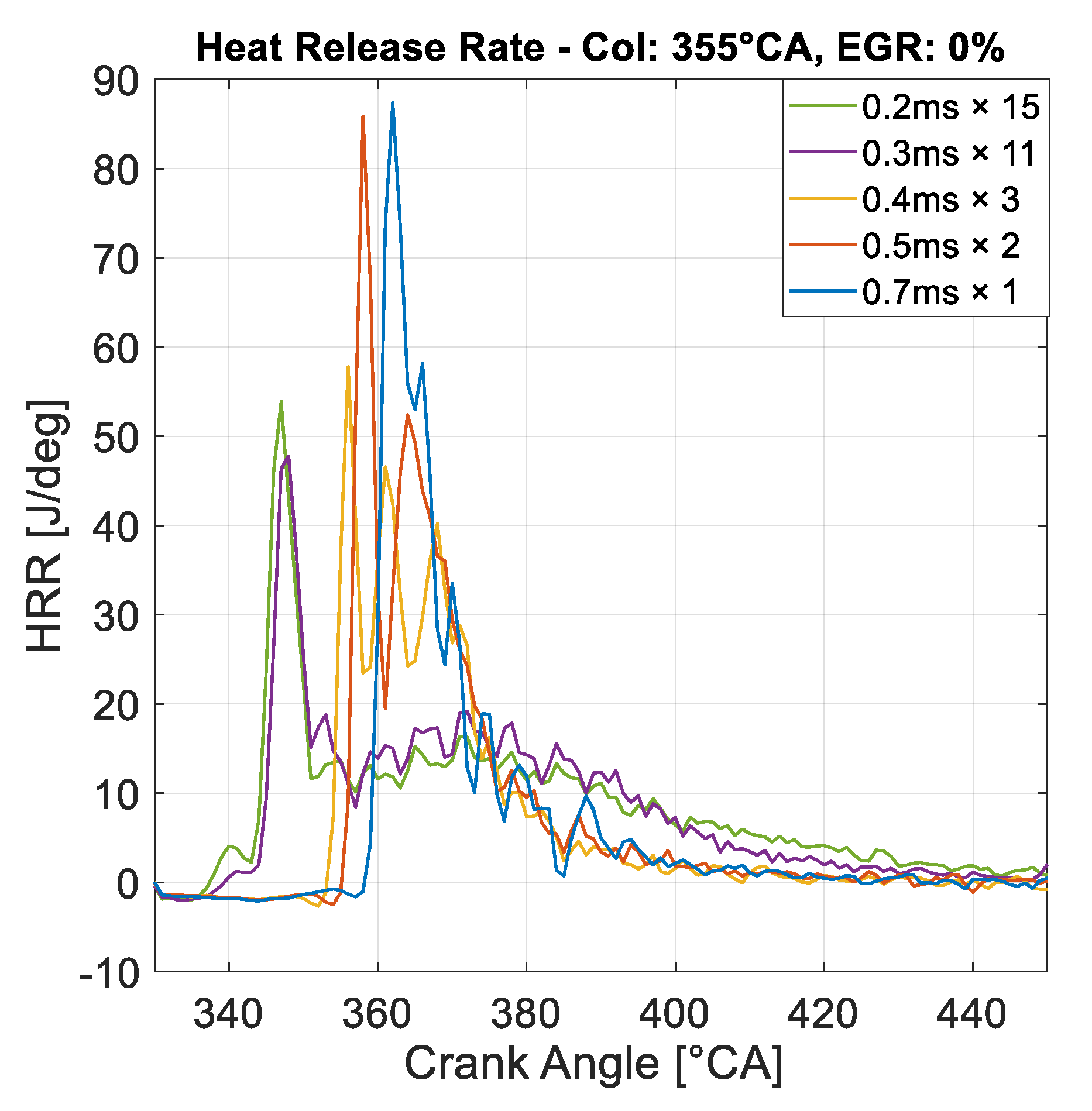
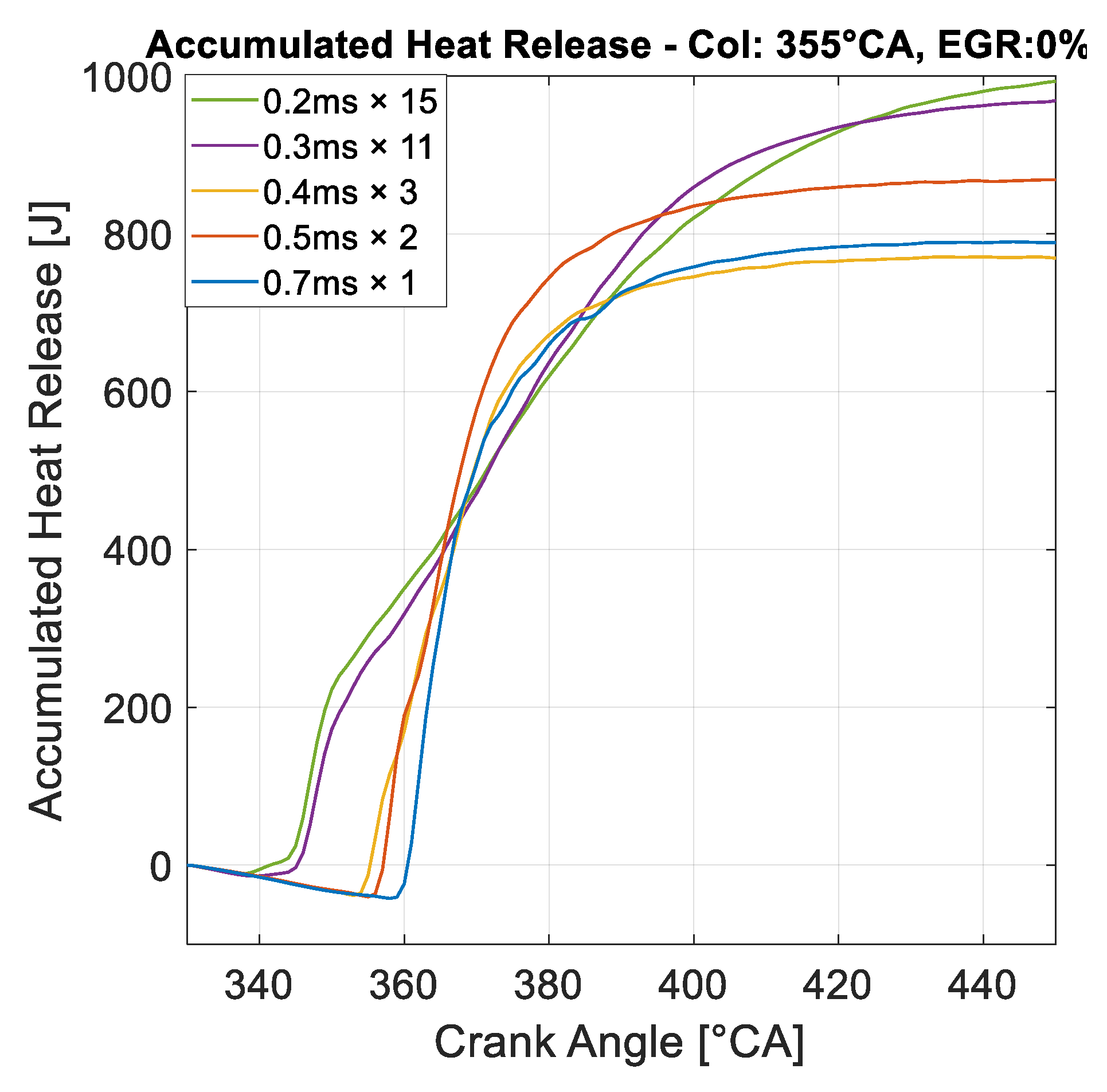
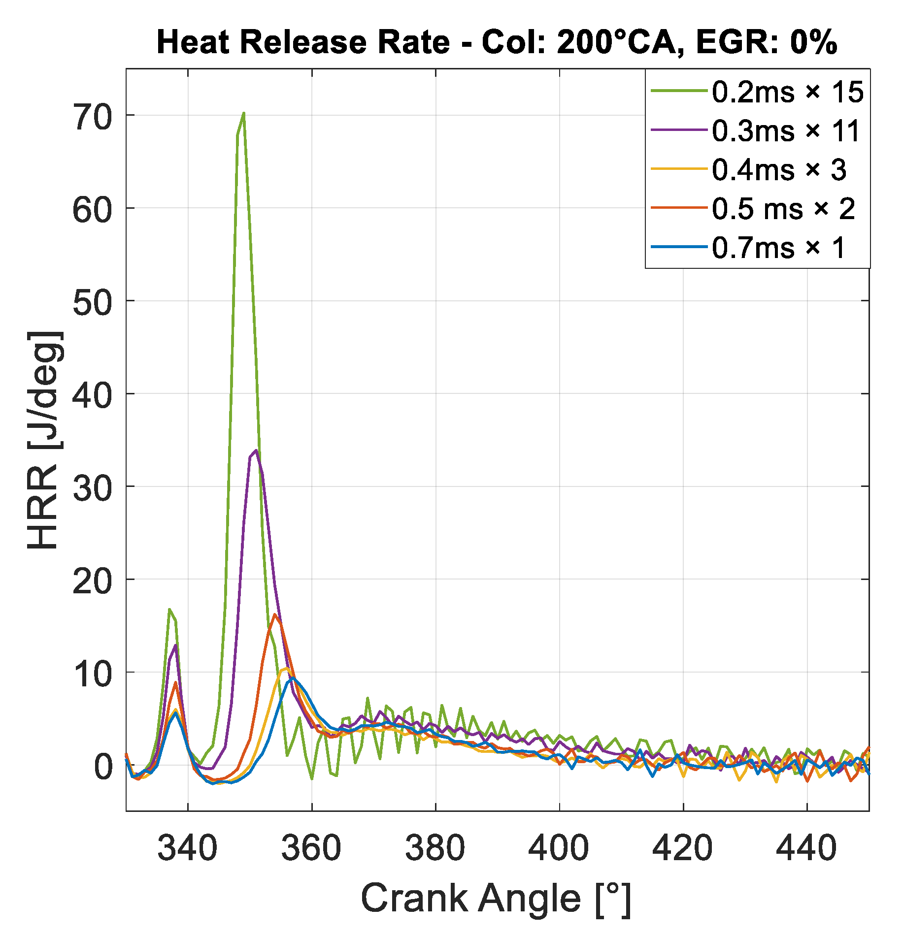
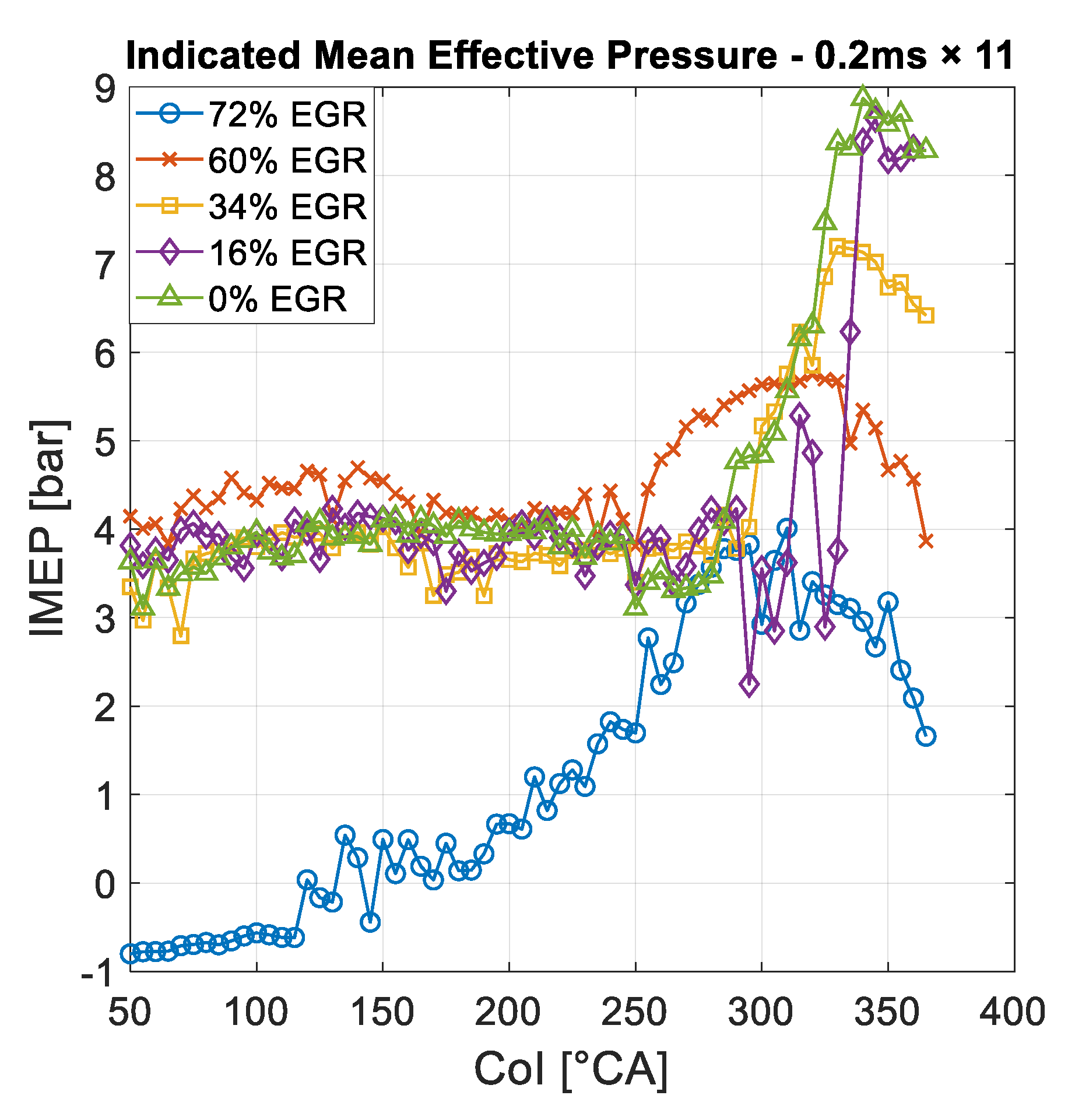
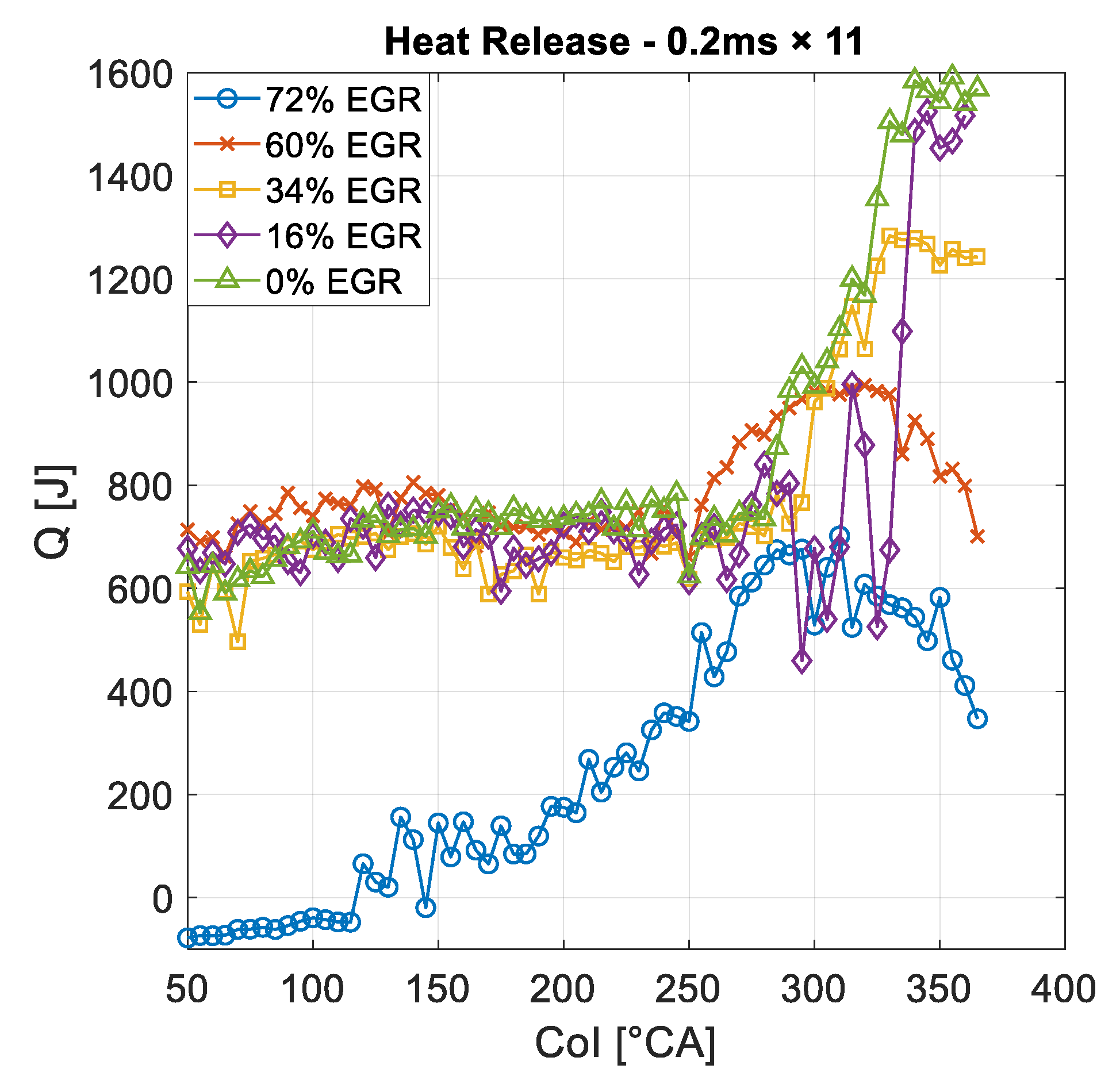
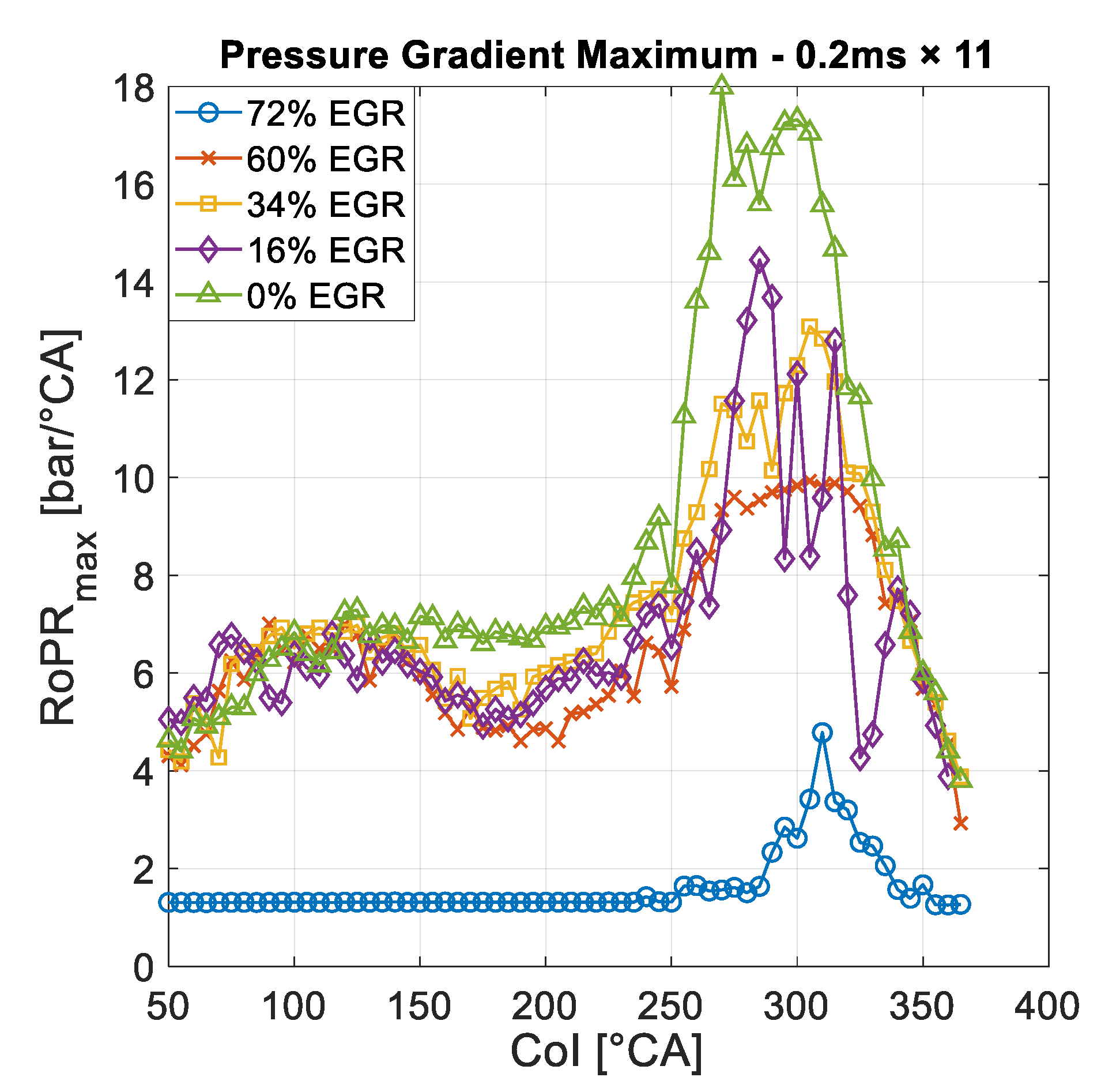
  • The heat release of MBI is higher than a single injection with the same amount of injected fuel. Owing to this rise, higher IMEP and indicated thermal efficiency is acquired. The calculated maximal thermal efficiency increased to 46% from 37%. The increased temperature and rate of pressure rise also indicates advanced burning conditions. The outcome reveals the enhanced air–fuel mixing property of the MBI.
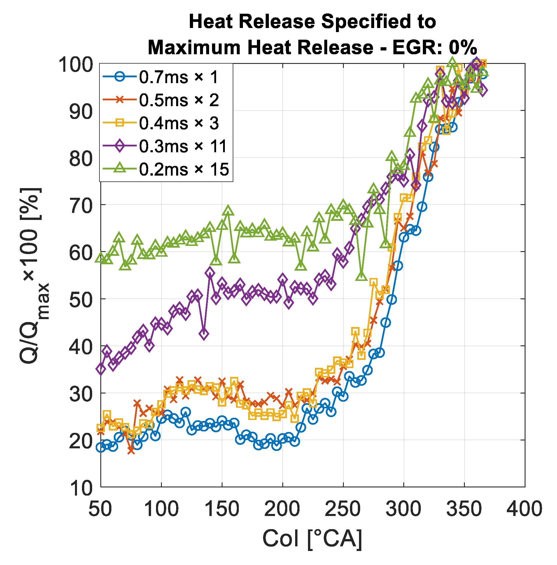
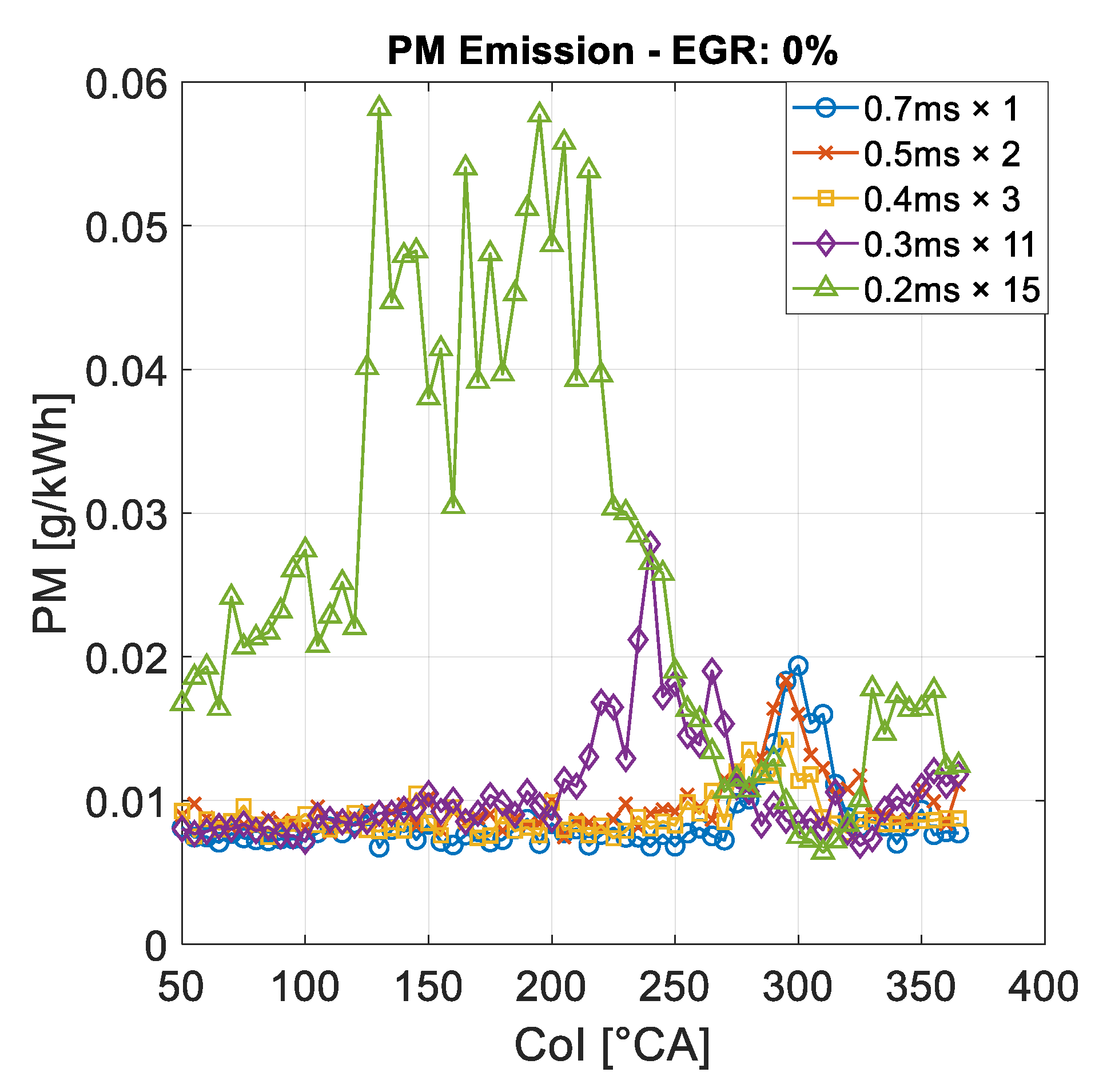
  • The reduction in heat release while advancing CoI was less in the case of MBI. The minimum heat release of the 0.2 ms × 15 MBI structure was 58% of this case’s maximal heat release, while the single injection’s minimal value was only 18%. This means a worse combustion at early single injections. The investigated HRRs also showed that the MBI combustion is superior at early injection timings. This is clear evidence for the wall-impingement-decreasing potential of MBI.
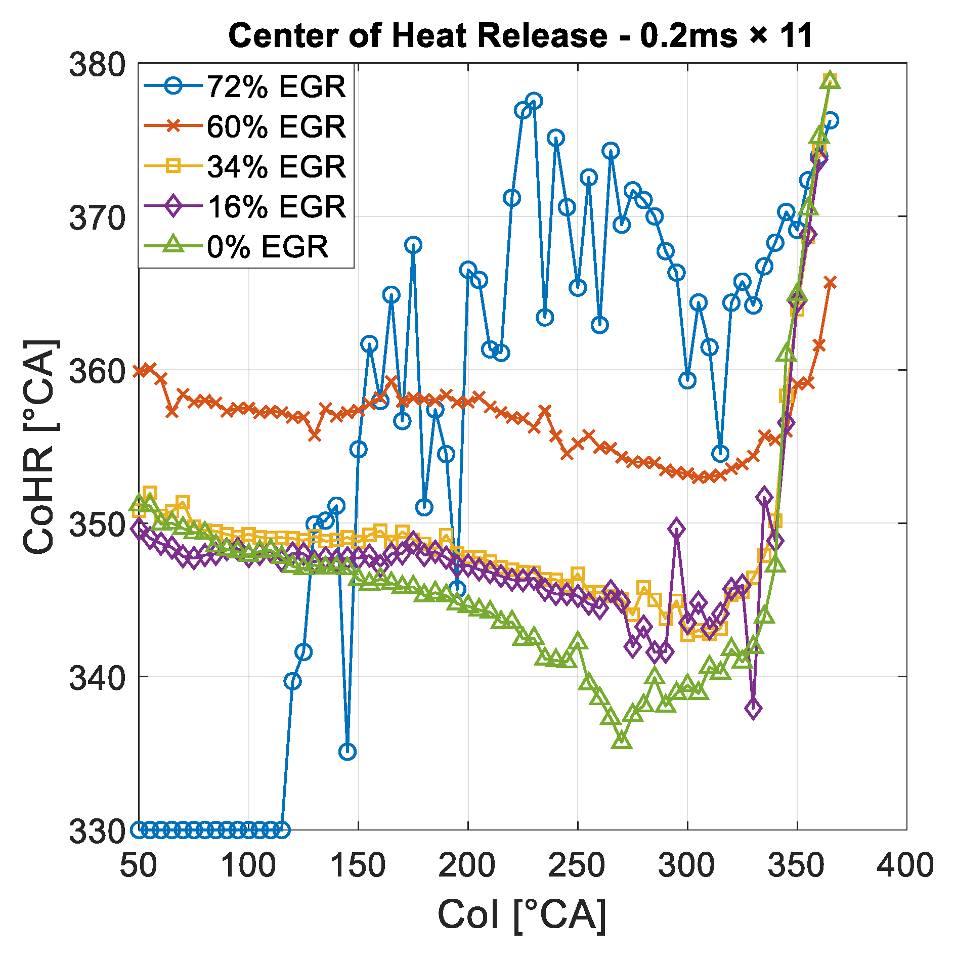
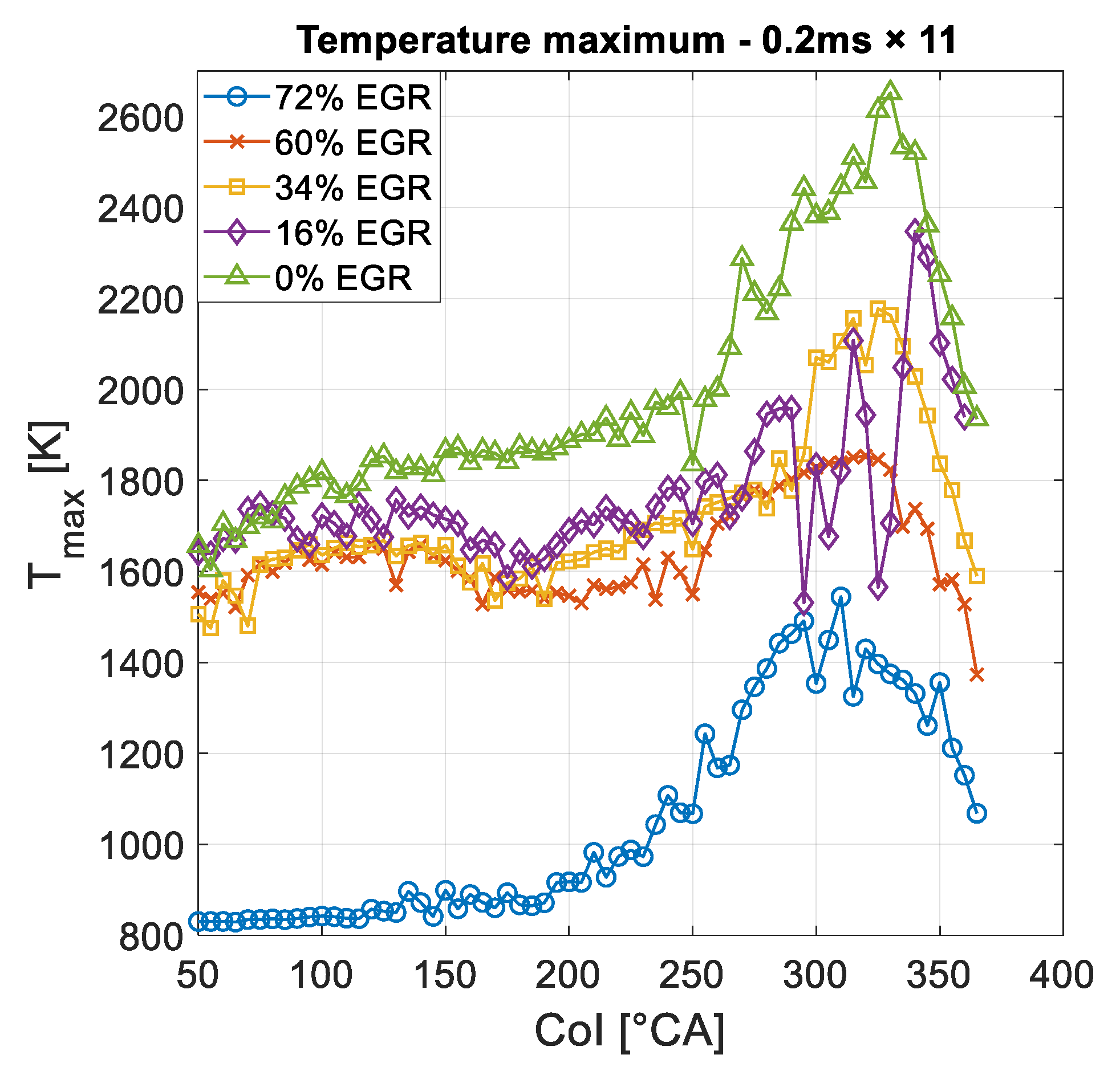
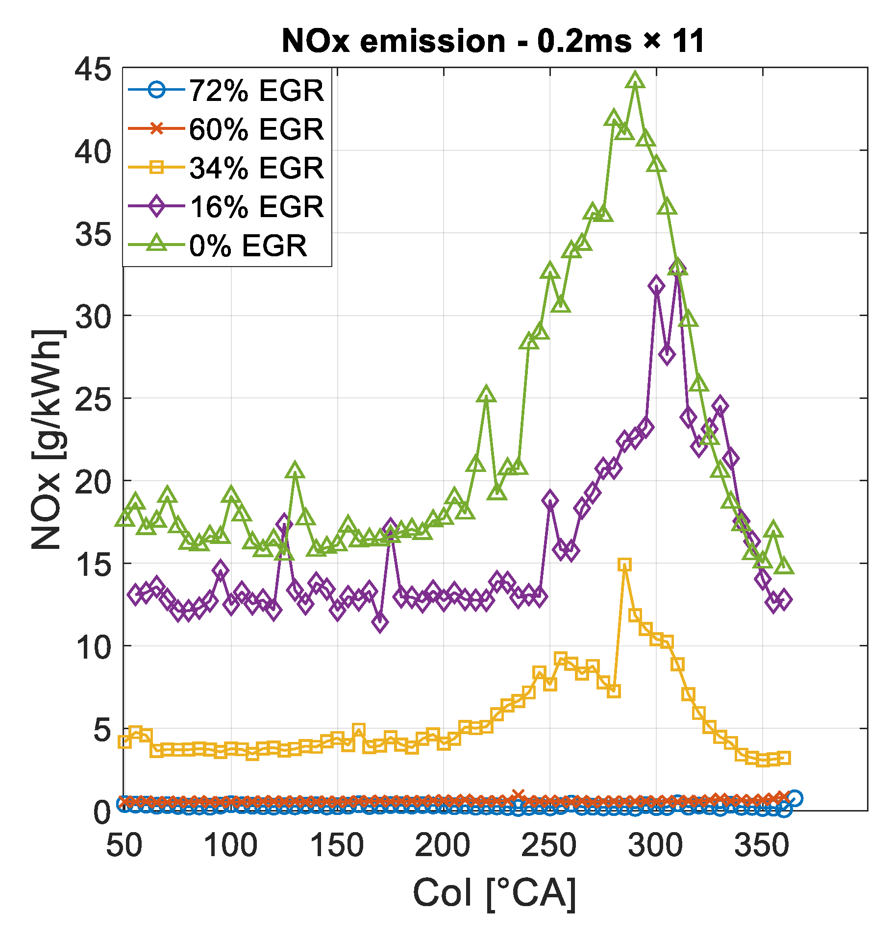
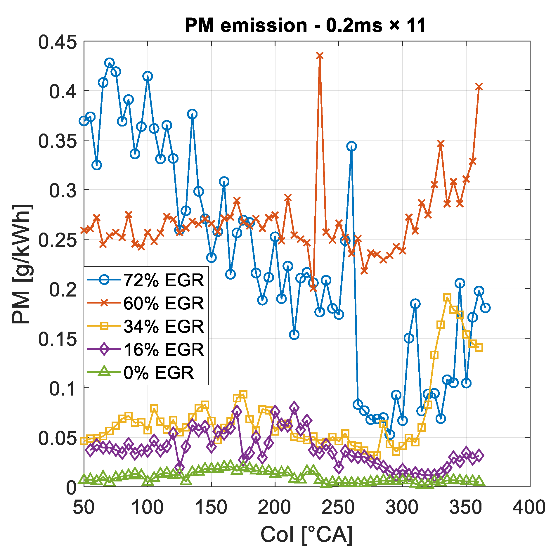
  • The EGR had the expected effects on the MBI. It retarded and prolonged the combustion, lowered the pressure gradient, the temperature, and the NOx emission. This is the same behavior that can be read in the literature of LTC engines. The EGR increased the PM emission, so a compromise is necessary.
  • The disadvantage of the MBI is the prolonged injection duration. This avoids the application of the method at injection timings close to TDCF, where the IMEP is the highest. There the long injection hangs into the combustion, which results in a diffusion flame, loss in mixture homogeneity, and increased PM emission. The solution for this problem could be the use of Continuous ballistic injection, which applies only one ballistic injection. This could result a shorter injection duration with the remaining advantages of the ballistic region.

Author Contributions

Conceptualization, M.V., G.G. and Á.B.; methodology, M.V.; software, M.V., Á.B. and G.G.; formal analysis, M.V.; investigation, M.V. and G.G.; resources, M.Z., Á.B. and Á.N.; data curation, M.V., G.G.; writing—original draft preparation, M.V.; writing—review and editing, M.Z.; visualization, M.V.; supervision, M.Z., Á.B. and Á.N.; project administration, M.Z. All authors have read and agreed to the published version of the manuscript.

Funding

This research received no external funding.

Conflicts of Interest

The authors declare no conflict of interest.

Abbreviations

CBI, Continuous Ballistic Injection; CoCoRS, Continuous Combustion Rate Shaping; CoI, Center of Injection; DiCoRS, Digital Combustion Rate Shaping; EGR, Exhaust Gas Recirculation; HCCI, Homogeneous Charge Compression Ignition; HECC, High-Efficiency Clean Combustion; HP-EGR, High Pressure Exhaust Gas Recirculation; IMEP, Indicated Mean Effective Pressure; LTC, Low Temperature Combustion; MBI, Multipulse Ballistic Injection; MK, Modulated Kinetics; NOx, Nitrogen Oxides; PCCI, Premixed Charge Compression Ignition; PM, particulate matter; PPC, Partially Premixed Combustion; PPCI, Partially-Premixed Compression Ignition; RCCI, Reactivity Controlled Compression Ignition; SPCCI, Spark Controlled Compression Ignition; TDC, Top Dead Center; TDCF, Top Dead Center Firing; THC, Total Hydrocarbons; TSCI, Thermally Stratified Compression Ignition.

References

  1. Singh, A.P.; Agarwal, A.K. Low-Temperature Combustion: An Advanced Technology for Internal Combustion Engines; Springer Nature Singapore Pte Ltd.: Singapore, 2018. [Google Scholar]
  2. Ya, B. The oxidation of nitrogen in combustion and explosions. Acta Physicochim. URSS 1946, 21, 557. [Google Scholar]
  3. Bendu, H.; Murugan, S. Homogeneous charge compression ignition (HCCI) combustion: Mixture preparation and control strategies in diesel engines. Renew. Sustain. Energy Rev. 2014, 38, 732–746. [Google Scholar] [CrossRef]
  4. Agarwal, A.K.; Singh, A.P.; Maurya, R.K. Evolution, challenges and path forward for low temperature combustion engines. Prog. Energy Combust. Sci. 2017, 61, 1–5. [Google Scholar] [CrossRef]
  5. Yao, M.; Zheng, Z.; Liu, H. Progress and recent trends in homogeneous charge compression ignition (HCCI) engines. Prog. Energy Combust. Sci. 2009, 35, 398–437. [Google Scholar] [CrossRef]
  6. Yang, J. Expanding the operating range of homogeneous charge compression ignition spark ignition dual mode engines in the homogeneous charge compression ignition mode. Int. J. Engine Res. 2005, 6, 279–288. [Google Scholar] [CrossRef]
  7. Thrlng, R.H. Homogeneous-Charge Compression Ignition (HCCI) Engines; SAE Technical Papers; SAE International: Warrendale, PL, USA, 1989. [Google Scholar]
  8. Park, S.W.; Reitz, R.D. Numerical study on the low emission window of homogeneous charge compression ignition diesel combustion. Combust. Sci. Technol. 2007, 179, 2279–2307. [Google Scholar] [CrossRef]
  9. Hardy, W.L.; Reitz, R.D. A Study of the Effects of High EGR, High Equivalence Ratio, and Mixing Time on Emissions Levels in a Heavy-Duty Diesel Engine for PCCI Combustion; SAE Technical Papers; SAE International: Warrendale, PL, USA, 2006. [Google Scholar]
  10. Mazda’s New Skyactiv-X Engine Gives New Life to Internal Combustion. IEEE Spectr. 2018. Available online: https://spectrum.ieee.org/transportation/efficiency/mazdas-new-skyactivx-engine-gives-new-life-to-internal-combustion (accessed on 2 May 2020).
  11. Li, J.; Yang, W.; Zhoub, D. Review on the management of RCCI engines. Renew. Sustain. Energy Rev. 2017, 69, 65–79. [Google Scholar] [CrossRef]
  12. Boldaji, M.R.; Sofianopoulos, A.; Mamalis, S.; Lawler, B. Effects of Mass, Pressure, and Timing of Injection on the Efficiency and Emissions Characteristics of TSCI Combustion with Direct Water Injection; SAE Technical Papers; SAE International: Warrendale, PL, USA, 2018. [Google Scholar]
  13. Walter, B.; Gatellier, B. Near zero NOx emissions and high fuel efficiency diesel engine: The NADI concept using dual mode combustion. Oil Gas Sci. Technol. Rev. IFP 2003, 58, 101–114. [Google Scholar] [CrossRef]
  14. Kimura, S.; Aoki, O.; Ogawa, H.; Muranaka, S.; Enomoto, Y. New Combustion Concept for Ultra-Clean and High-Efficiency Small DI Diesel Engines; SAE Technical Papers; SAE International: Warrendale, PL, USA, 1999. [Google Scholar]
  15. Zeng, W.; Xie, M. A novel approach to reduce hydrocarbon emissions from the HCCI engine. Chem. Eng. J. 2008, 139, 380–389. [Google Scholar] [CrossRef]
  16. Park, S.H.; Yoon, S.H.; Lee, C.S. Effects of multiple-injection strategies on overall spray behavior, combustion, and emissions reduction characteristics of biodiesel fuel. Appl. Energy 2010, 88, 88–98. [Google Scholar] [CrossRef]
  17. Mendez, S.; Thirouard, B. Using multiple injection strategies in diesel combustion: Potential to improve emissions, noise and fuel economy trade-off in low cr engines. SAE Int. J. Fuels Lubr. 2008, 1, 662–674. [Google Scholar] [CrossRef]
  18. O’Connor, J.; Musculus, M. Post injections for soot reduction in diesel engines: A review of current understanding. SAE Int. J. Engines 2013, 6, 400–421. [Google Scholar] [CrossRef] [Green Version]
  19. Jörg, C.; Schnorbus, T.; Jarvis, S.; Neaves, B.; Bandila, K.; Neumann, D. Feedforward control approach for digital combustion rate shaping realizing predefined combustion processes. SAE Int. J. Engines 2015, 8, 1041–1054. [Google Scholar] [CrossRef]
  20. Scafati, F.T.; Pirozzi, F.; Montanaro, A.; Allocca, L. Real Time Control of GDI Fuel Injection during Ballistic Operation Mode; SAE Technical Papers; SAE International: Warrendale, PL, USA, 2015. [Google Scholar]
  21. Payri, R.; de la Morena, J.; Pagano, V.; Hussain, A.; Sammut, G.; Smith, L. One-dimensional modeling of the interaction between close-coupled injection events for a ballistic solenoid injector. Int. J. Engine Res. 2019, 20, 452–469. [Google Scholar] [CrossRef]
  22. Vass, S.; Zöldy, M. Detailed model of a common rail injector. Acta Univ. Sapientiae Electr. Mech. Eng. 2019, 11, 22–33. [Google Scholar] [CrossRef] [Green Version]
  23. Mei, D.; Yue, S.; Zhao, X.; Hielscher, K.; Baar, R. Effects of center of heat release on combustion and emissions in a PCCI diesel engine fuelled by DMC-diesel blend. Appl. Therm. Eng. 2017, 114, 969–976. [Google Scholar] [CrossRef]
  24. Yao, M.; Zhang, B.; Zheng, Z.; Chen, Z.; Xing, Y. Effects of exhaust gas recirculation on combustion and emissions of a homogeneous charge compression ignition engine fuelled with primary reference fuels. Proc. Inst. Mech. Eng. Part D J. Automob. Eng. 2007, 221, 197–213. [Google Scholar] [CrossRef]
  25. Yap, D.; Karlovsky, J.; Megaritis, A.; Wyszynski, M.L.; Xu, H. An investigation into propane homogeneous charge compression ignition (HCCI) engine operation with residual gas trapping. Fuel 2005, 84, 2372–2379. [Google Scholar] [CrossRef]
Figure 1. Example of injector characteristics. The lower slope before 0.3 ms is the result of the ballistic injection.
Energies 14 03727 g001
Figure 2. Examples of two comparable injection structures. The doses are the same and both CoIs are 295 °CA.
Energies 14 03727 g002
Figure 3. The IMEP of the investigated structures with the same dose in the function of CoI without EGR.
Energies 14 03727 g003
Figure 4. The heat release of the investigated structures with the same dose in the function of CoI without EGR.
Energies 14 03727 g004
Figure 5. The heat release specified to maximum heat release. MBI has less heat release reduction at early CoIs.
Energies 14 03727 g005
Figure 6. The center of heat release of the investigated structures with the same dose in the function of CoI without EGR.
Energies 14 03727 g006
Figure 7. The pressure gradient maxima of the investigated structures with the same dose in the function of CoI without EGR.
Energies 14 03727 g007
Figure 8. The temperature maxima of the investigated structures with the same dose in the function of CoI without EGR.
Energies 14 03727 g008
Figure 9. The NOx emission of the investigated structures with the same dose in the function of CoI without EGR.
Energies 14 03727 g009
Figure 10. The PM emission of the investigated structures with the same dose in the function of CoI without EGR.
Energies 14 03727 g010
Figure 11. The heat release rates of the investigated structures with the same dose in the function of the crank angle without EGR. The CoI is 355 °CA in each case.
Energies 14 03727 g011
Figure 12. The accumulated heat release of the investigated structures with the same dose in the function of crank angle without EGR. The CoI is 355 °CA in each case.
Energies 14 03727 g012
Figure 13. The heat release of the investigated structures with the same dose in the function of crank angle without EGR. The CoI is 200 °CA in each case.
Energies 14 03727 g013
Figure 14. The IMEP of the 0.2 ms × 11 structure with different EGR rates in the function of CoI.
Energies 14 03727 g014
Figure 15. The heat release of the 0.2 ms × 11 structure with different EGR rates in the function of CoI.
Energies 14 03727 g015
Figure 16. The center of heat release of the 0.2 ms × 11 structure with different EGR rates in the function of CoI.
Energies 14 03727 g016
Figure 17. The pressure gradient maxima of the 0.2 ms × 11 structure with different EGR rates in the function of CoI.
Energies 14 03727 g017
Figure 18. The temperature maxima of the 0.2 ms × 11 structure with different EGR rates in the function of CoI.
Energies 14 03727 g018
Figure 19. The NOx emission of the 0.2 ms × 11 structure with different EGR rates in the function of CoI.
Energies 14 03727 g019
Figure 20. The PM emission of the 0.2 ms × 11 structure with different EGR rates in the function of CoI.
Energies 14 03727 g020
Table 1. Main parameters of the Cummins ISBe 170 30 commercial diesel engine.
Engine displacement3922 cm3
Bore102 mm
Stroke120 mm
Compression ratio17.3
Rated effective power125 kW
Table 2. Cases of the first experiment.
First Experiment
Load50 Nm (1250 rpm)
Dose27 mg
EGR0%
Structure NameSingle Injection DurationNumber of Injections
0.7 ms × 10.7 ms1
0.5 ms × 20.5 ms2
0.4 ms × 30.4 ms3
0.3 ms × 110.3 ms11
0.2 ms × 150.2 ms15
Table 3. Cases of the second experiment.
Second Experiment
Load50 Nm (1250 rpm)
Dose31 mg
Structure Name0.2 ms × 11
EGR0%16%34%60%72%
Publisher’s Note: MDPI stays neutral with regard to jurisdictional claims in published maps and institutional affiliations.

