Article

Double Fed Induction Generator Control Design Based on a Fuzzy Logic Controller for an Oscillating Water Column System

by
Cristian Napole
*,
Oscar Barambones
*,
Mohamed Derbeli
*,
José Antonio Cortajarena
,
Isidro Calvo
,
Patxi Alkorta
and
Pablo Fernandez Bustamante
System Engineering and Automation Deparment, Faculty of Engineering of Vitoria-Gasteiz, Basque Country University (UPV/EHU), 01006 Vitoria-Gasteiz, Spain
*
Authors to whom correspondence should be addressed.
Energies 2021, 14(12), 3499; https://doi.org/10.3390/en14123499
Submission received: 26 May 2021 / Revised: 9 June 2021 / Accepted: 11 June 2021 / Published: 12 June 2021
(This article belongs to the Special Issue Design and Implementation of Control Schemes for Wave Energy Systems)

Abstract

:
Oscillating water column (OWC) systems are water power generation plants that transform wave kinetic energy into electrical energy by a surrounded air column in a chamber that changes its pressure through the waves motion. The chamber pressure output spins a Wells turbine that is linked to a doubly fed induction generator (DFIG), flexible devices that adjust the turbine speed to increase the efficiency. However, there are different nonlinearities associated with these systems such as weather conditions, uncertainties, and turbine stalling phenomenon. In this research, a fuzzy logic controller (FLC) combined with an airflow reference generator (ARG) was designed and validated in a simulation environment to display the efficiency enhancement of an OWC system by the regulation of the turbine speed. Results show that the proposed framework not only increased the system output power, but the stalling is also avoided under different pressure profiles.

1. Introduction

Global warming is a subject undergoing intense study nowadays as a consequence of the pollution generated by fossil fuels. The production of energy is shifting the sources to renewables which have less CO 2 production; this is one of the main greenhouse gases whose emissions need to be reduced 80–95% by 2050 [1]. According to the Energy Road-map of the European Commission [2], this objective can be reached provided that renewable sources will cover at least 40% of the whole production. Despite the fact that photo-voltaic and wind sources are being focused on in research, hydro-power is still one of the biggest sources for renewable electricity generation [3]. The latter implies that a turbine propeller is being moved through water force; however, an alternative is the usage of ocean waves to cause a propeller movement with air in an oscillating water column (OWC) device.
An OWC consists of a partial submerged chamber where the inside water oscillates as a consequence of the wave motion, and a turbine moves with the air pressure change inside the chamber where a generator is linked to the turbine and a power converter. With regard to the turbine, Wells type is the most used one due to its simplicity, costs involved, and the fact that energy extraction can be performed at low airflow rates [4,5]. However, the produced power is nonlinear as it is mainly affected by the wave characteristics [6].
Variable features are not only present in OWC but also in wind turbine generators (WTG), which are usually linked to a doubly-fed induction generator (DFIG), and, therefore, the same theories can be used in OWC. DFIGs are used to regulate the output power through the voltage and frequency control (VFC) in systems that have rapid changes or variable rotor speed [7,8]. The outcome of a VFC configuration that is connected to the grid manages a low nominal power (near 30%) [9]. Even though full converters (FC) can increase the performance of the overall system [10], the costs of these devices are higher than a DFIG due to the usage of rare earth materials for its production [11].
The uncertainty demeanor of the waves is dependent on the weather, which implies that OWC performance can change everyday; this results in a power variance that can affect the generator output [12]. Furthermore, a main disadvantage of Wells turbines is the stalling phenomenon that happens at low rotational speeds [13,14]. Both detriments can be compensated through the use of a control strategy that regulates the rotor speed. One of the first research studies where the stalling control strategies were investigated was carried out by Jayashankar et al. [15]; in this work, the rotor resistance was changed by using different schemes: two resistance change and continuous resistance changing. Outcomes showed improvements in the reduction of the main drawback. Other classical strategies such as proportional-integral-derivative (PID) and its variants had also been used in DFIG systems—for instance, the authors of [16] used a conventional PID contrasted with a fractional order proportional-integral-derivative (FOPID) for a WTG. In this study, the results obtained showed a better performance in the FOPID simulation for different proposed scenarios. However, the PID limitations are related to its robustness which can be compensated by the FOPID, although its industrialization is still a challenge in terms of costs [17]. In addition, advanced linear structures such as H have been implemented in WTG, where the objective was also the speed control [18]; results depicted a suitable demeanor when coping with uncertainties. However, linear controllers have certain restraints when robustness is required in a nonlinear system such as a DFIG.
The significance of nonlinear aspects existing in DFIGs are aimed to use controllers that can counteract with these features. Sliding mode control (SMC) is a classic example of this type due to its high robustness against the rejection of disturbances and perturbations. The authors of [19] implemented an SMC on a DFIG system with an exponential reaching law where the intention was to reduce the chattering. In spite of the improvements achieved, which were enhanced in comparison with a conventional SMC, the main drawback of the sliding controllers is the increase of the energy consumption. However, this effect is also caused due to the unmodeled dynamics which imply that the chattering elimination is an idealization [20]. Another advanced approach is the usage of artificial neural networks (ANN) for the tuning of a frequency controller of a DFIG based on weather conditions. According to the study generated by the authors of [21] with the latter mentioned structure, the results were contrasted against a fixed gain controller, and significant improvements were observed. However, one of the main disadvantages of ANN employment for weather forecasts is that several input variables should be used to obtain a precise result [22]. Another well used structure is fuzzy logic control (FLC) which is known for its robustness against disturbances and uncertainties for large scale systems as well as practicality in terms of implementation [23,24]. The usefulness of this technique can be augmented even to system modeling like the authors of [25] did in their study; in this case, they deduced a PID based on FLC for a fuzzy linear model. Actually, it is recommended over methods such as SMC [26]. This framework requires an operator expertise to design and tune the controller action depending on the needs for the system [27].
In this research, an FLC type-1 was designed and implemented within an airflow reference generator. This controller has management capabilities that can help to deal with control uncertainties, operational changes, and disturbances along with the configuration of internal rules [28]. On the other hand, OWC systems are commonly regulated using the maximum available energy level of the turbine through a constant reference; however, in this research, an airflow reference generator (ARG) was designed so that the air pressure could be tracked at each wave motion. Thus, the designed FLC and ARG were combined with a DFIG rotor current regulation aimed to control the turbine speed so that the power extraction could be maximized.
This research paper is organized as follows: Section 2 introduces the OWC plant model, a rough analysis of the stalling phenomenon, the DFIG model used, and control design. Section 3 provides the outcomes of the simulations where the stalling is highlighted. Finally, Section 4 focuses on the attainments gathered along the development of the research.

2. Materials and Methods

2.1. OWC Plant Model

Figure 1 shows a simple diagram of an OWC system. Assuming that the sea waves are oscillating their height, the air housed in the chamber will behave similarly so that the kinetic energy and the air pressure will help the turbine to spin. This implies that several tools from WTG models can be used since the working principle is similar. For instance, the extracted power P i n is expressed like the following Equation (1) [29].
P i n = d P + ρ v x 2 2 v x a
where d P [Pa] is the turbine pressure drop, v x [m/s] is the airflow speed, ρ [ kg / m 3 ] is the air density, and a [ m 2 ] is the cross-sectional area of the turbine duct. The expression consists of two terms where d P is the air–pressure difference in the chamber, and ρ v x 2 / 2 is the air kinetic energy. The speed direction in the chamber fluctuates because, when the waves increase the flood of the chamber, the inner pressure is increased; on the contrary, when the water retracts, the pressure is released. Despite the fact that Wells turbines always turn in the same direction, these are able to carry on moving independently of the airflow direction [30]. The mathematical model of a Wells turbine is established by the following expressions [15]:
d P = C a k t 1 a v x 2 + ( r ω ) 2
T t = C t k t r [ v x 2 + ( r ω ) 2 ]
T t = C t r a C a d P
k t = ρ b n l 2
ϕ = v x r w
q = v x a
η = T t w q d P
where d P [ N / m 2 ] is the differential pressure, C a is a power coefficient, K t [ kg · m ] is a turbine constant, r [ m ] is the mean turbine radius, ω [ rad / s ] is the turbine angular velocity, T t is the generated torque in the turbine [ N · m ] , C t is a torque coefficient, b [ m ] is the blade height, l [ m ] is the blade chord length, n is the number of blades, ϕ is the flow coefficient, q [ m 3 / s ] is the air flow-rate, and η is the turbine efficiency. Although the aim of this work is the enhancement of the latter mentioned parameter, it is important to notice that the whole OWC system efficiency is defined as η O W C = η · η h , where η h is related to the OWC hydrodynamic efficiency. Further details can be found in the research made by the authors of [31].
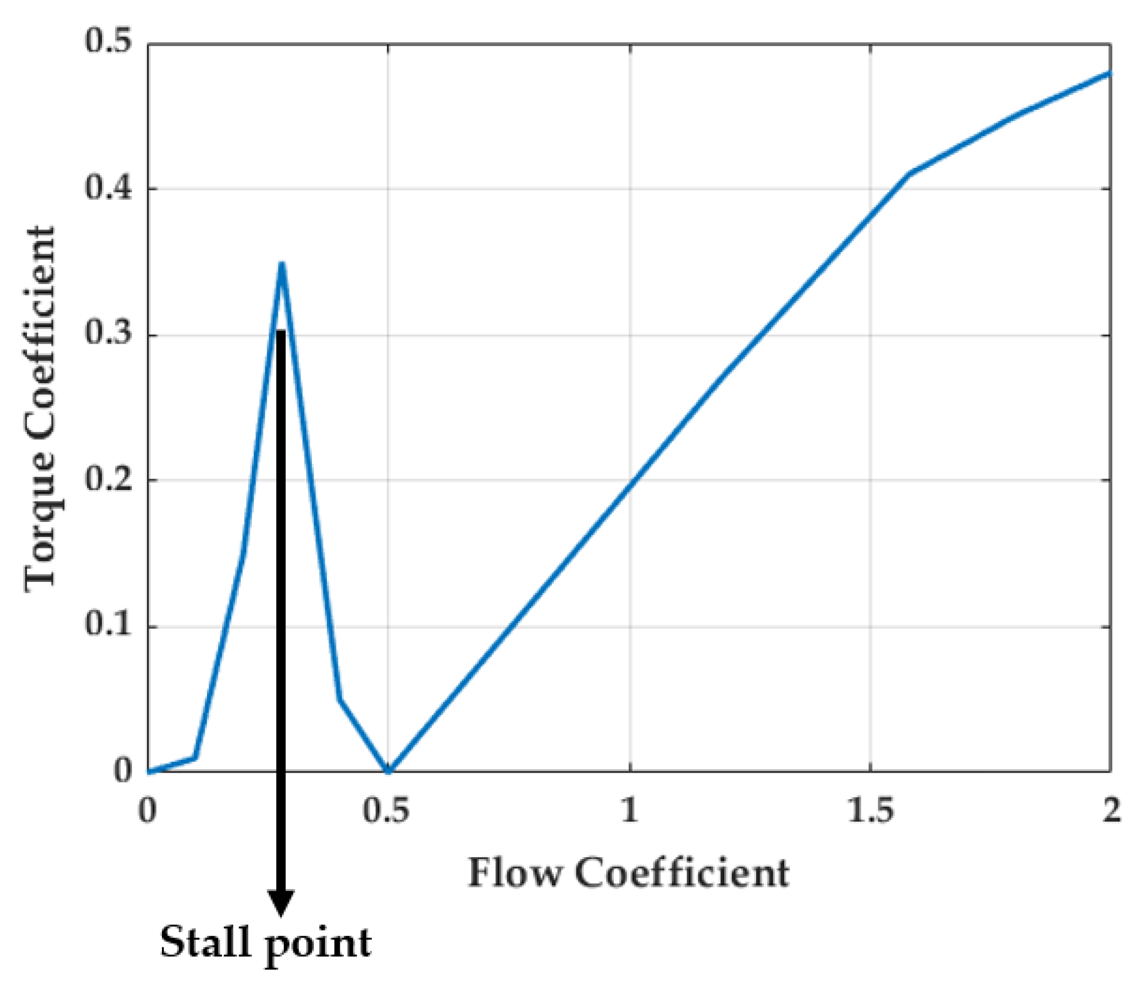
Previous definitions showed that the power and the torque are proportionally related by the torque and flow coefficients. Figure 2 is an example used from a specific Wells turbine where several points deserve to be highlighted. The first section begins with the start-up section until a critical value where ϕ is near 0.3; this is known as the stall-point which implies that the relative angle between the tangential velocity and the axial velocity has a critical value (usually near 14°). As the boundary layer starts to be detached near the turbine airfoils trailing edge, the performance decreases dramatically as it can be seen afterwards where the torque coefficient plummets.
In this study, it is assumed that the working range is between the turbine onset and ϕ o p t = 0.29 , which is a slight value before the stall occurs. Based on Equation (6), the rotational speed is defined as following for a speed regulation:
w * = v x r · ϕ o p t .
On the other hand, the coupling between the turbine and the generator is assumed as first order dynamics [30]:
J ω ˙ + B ω = T t γ T e
where J is the inertia moment, ω is the turbine rotational speed, B is the viscosity coefficient, T t is the turbine torque, γ is a gear ratio between turbine and generator, and T e is the generator torque. The tracking of the rotational speed is highly dependent on the DFIG features that should be modeled as well.
A vector control technique is used for the DFIG modeling whose advantage is related to the stator flux reference frame. This entails that the d-axis is aligned with the stator flux linkage and therefore ψ d s = ψ s and ψ q s = 0. Hence, based on the electric relations, it can be expressed based on the research made by authors of [32] as follows:
i q s = L m i q r L s
i d s = L m ( i m s i d r ) L s
i m s = v q s r s i q s w s L m
T e = 3 p 4 L m 2 i m s i q r L s
v q r = r r i q r + σ L r d i q r d t + s w s σ L r i d r + L m 2 i m s L s
v d r = r r i d r + σ L r d i q r d t s w s σ L r i q r
where:
  • i q s and i q s : q-d components for the stator current.
  • i q r and i q r : q-d components for the rotor current.
  • L s , L r , L m : Inductances of stator, rotor, and mutual, respectively.
  • i m s : magnetizing stator current considered as constant since the stator resistance sways in a slight proportion as the stator is linked straight to the grid [8,33].
  • w s : angular velocity the synchronous reference.
  • v q r and v q r : q-d components of the rotor voltage.
  • σ = 1 L m 2 L s L r .
  • p: pole numbers.

2.2. Type-1 Fuzzy Logic Controller

The proposed FLC aims to regulate the speed of the turbine using the rotor current i q r * as a control signal. One of the main advantages of FLC is the ground of its design that is based on the user experience of the system to be controlled. In this case, a type-1 FLC structure was defined where the error and its derivative were, respectively, normalized with K E and K E d . Thus, these were the inputs to the FLC block, whereas the output was augmented with a gain K o to yield a suitable control signal and tracking performance. An overview of the structure is shown in Figure 3.
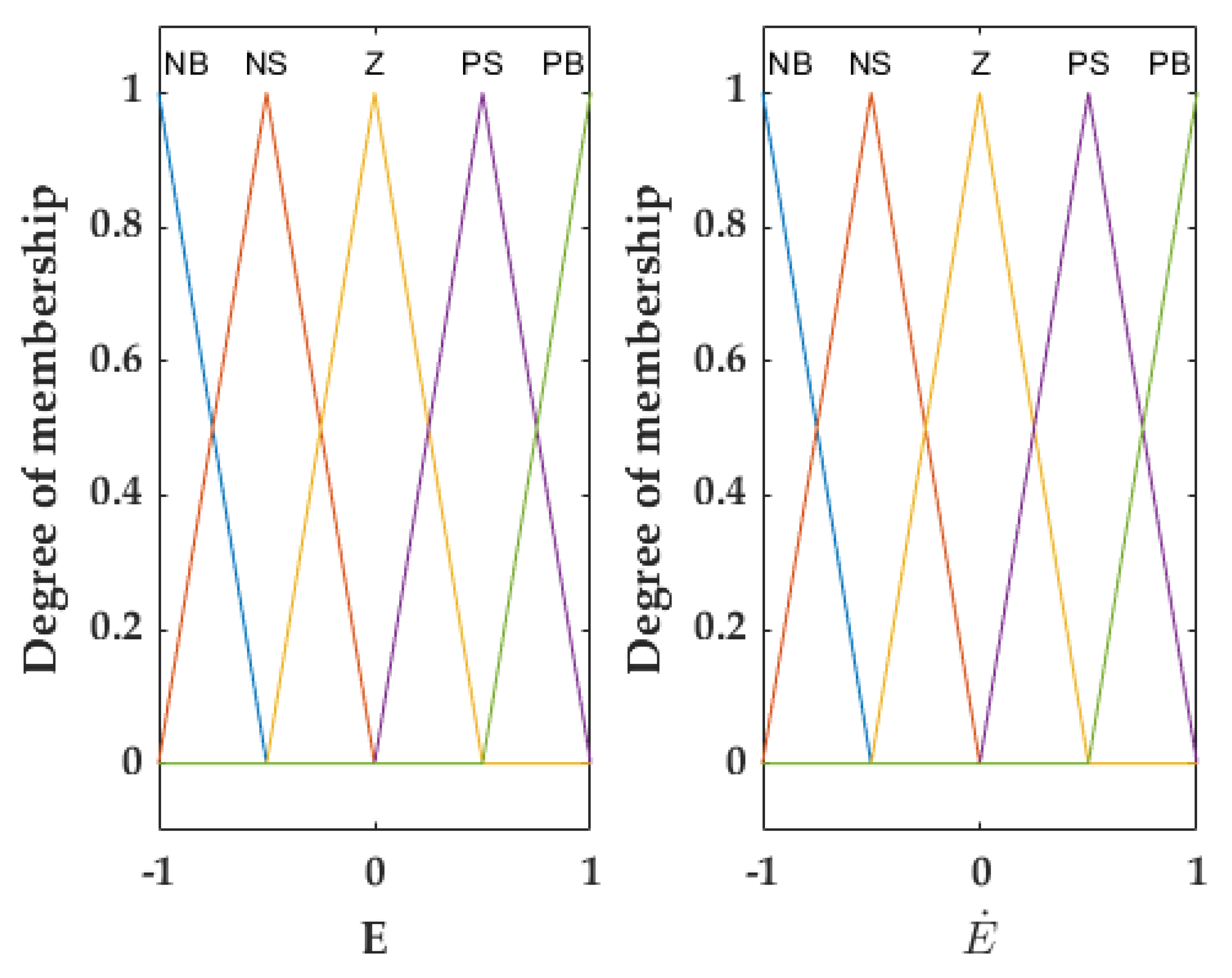
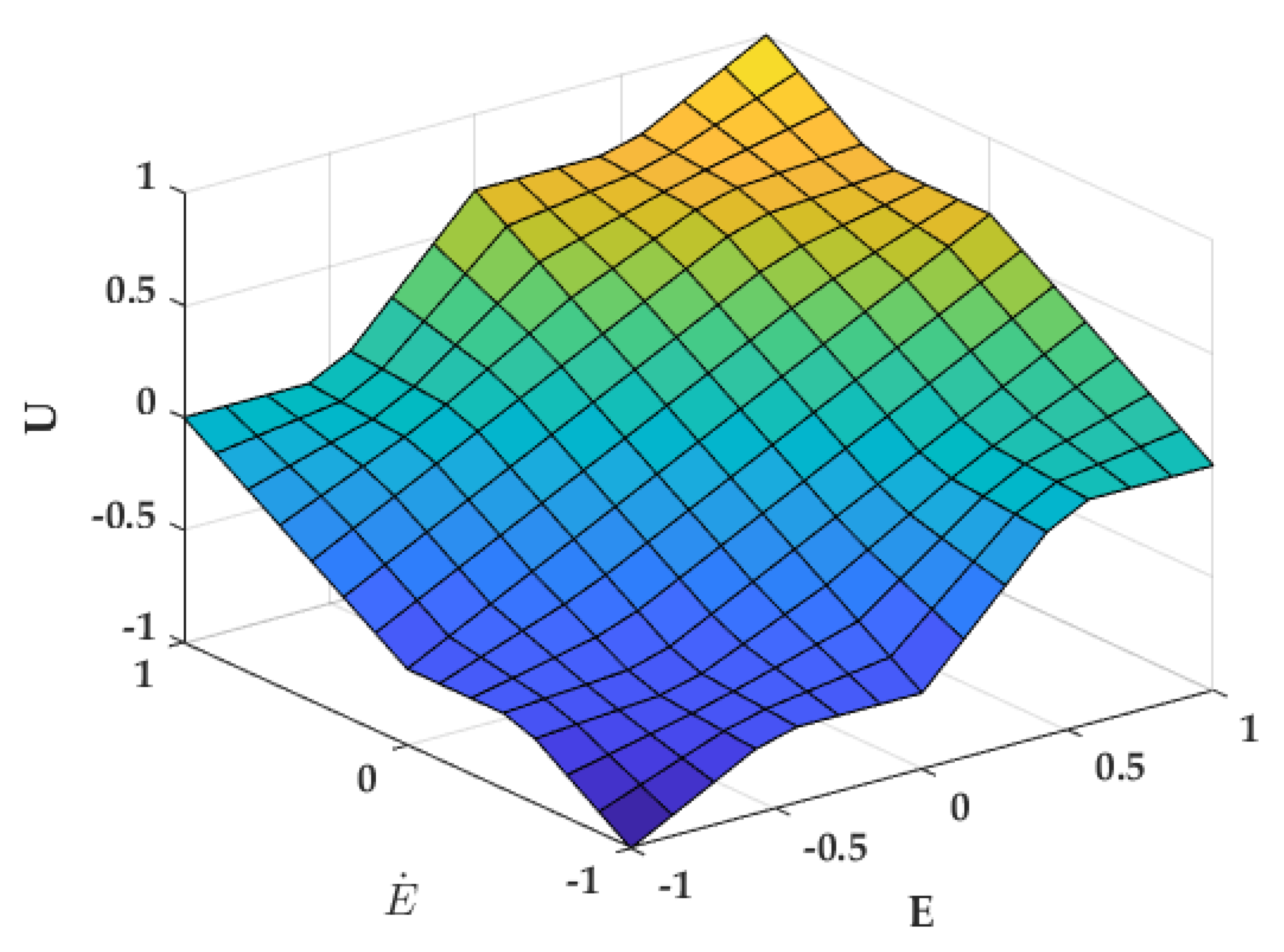
Three main steps are related to the FLC block to reach an established control signal. At first, the normalized error and its derivative face the fuzzifier block that designates the corresponding membership function based on a criterion with a uniform and overlapped range between −1 and 1 in triangular shapes. These values had been designated based on the study made by the author of [34]. Further details about the used membership functions are exposed in Figure 4. These have been associated with linguistic rules that have been defined as negative big (NB), negative medium (NM), negative small (NS), zero (Z), positive small (PS), positive medium (PM), and positive big (PB). The following step is the inference mechanism where previous linguistic definitions are evaluated according to if-then type rules formerly established [35]. In this case, the rules were settled according to Table 1. The last step is the defuzzification where the results previously gathered through the logic of the controller are translated into numerical values [36]; these were uniformly discretized between −1 and 1. In accordance with the established linguistic rules and the output numerical values of the defuzzification, the obtained control surface is displayed in Figure 5.

2.3. Simulation Design

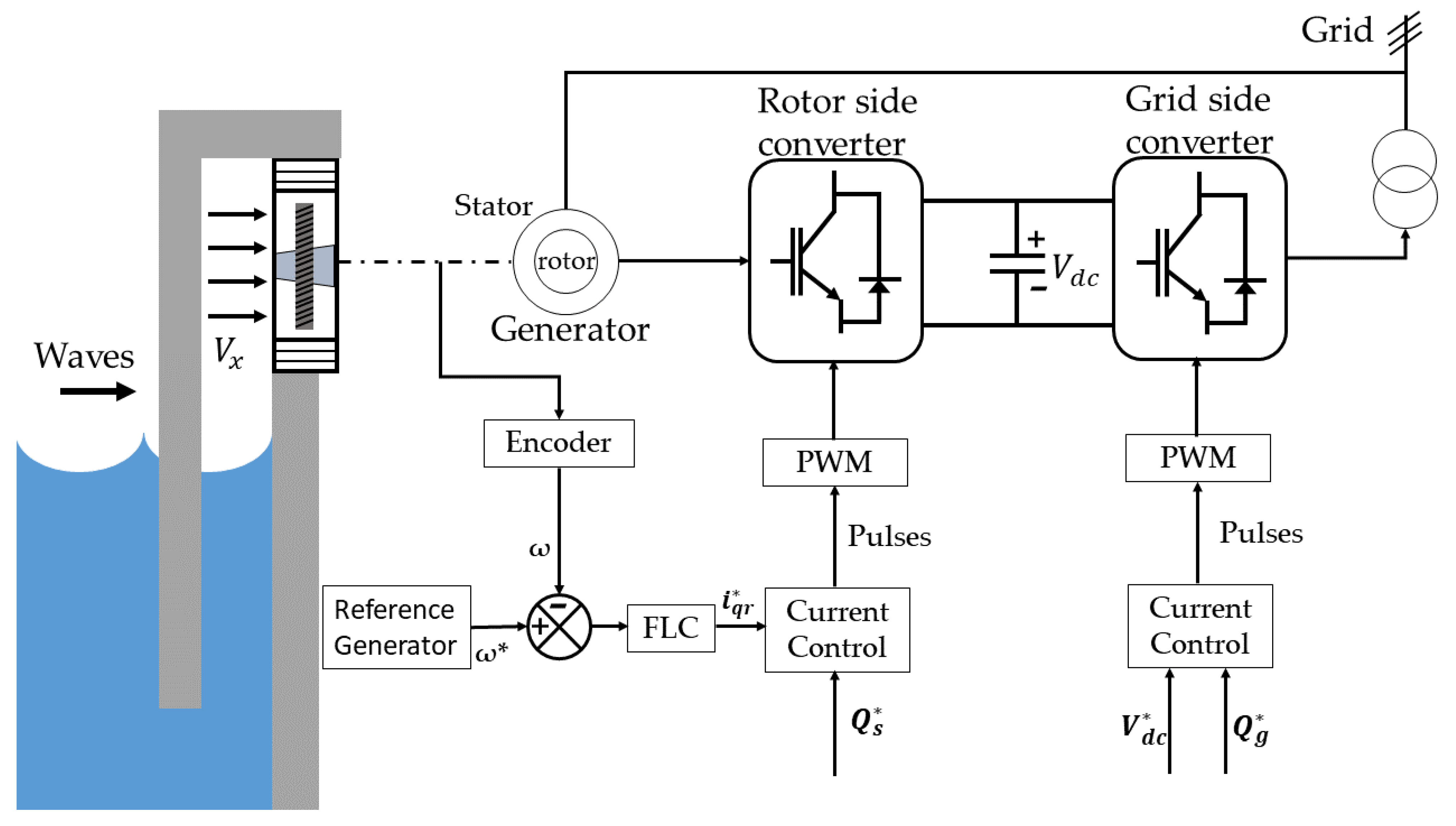
Previously described models and controllers have been developed and implemented with Simulink through SimPowerSystems library from Mathworks. Figure 6 is a schematic description of the whole OWC structure; in this case, the rotational velocity of the wells turbine is assumed to be measured by an encoder which provides ω . The FLC provides a regulated rotor current that is related to the generator torque and velocity; the error is calculated from the measures ω and the ARG through the chamber pressure.
It was considered that wave shape behaves with a sine function that is reflected in the chamber pressure drop and with a period of 10 s (an average value of sea waves [37]), but the amplitude has been changed for a lower and a high value. The choice was based on the stall phenomenon since, in the first case, the turbine operates normally, whereas, in the second stage, the device operates near the critical point.
A back-to-back converter was established using a rotor side converter (RSC) and a grid side converter (GSC). The GSC preserves constant voltage of the DC-link and regulates the reactive output power, which implies that this device allows the power flow between rotor to stator [38]. The rotor side converter (RSC) objective is to repel fluctuations that may affect the torque and stator reactive power [39]. The RSC and the GSC are linked by a filter that aims to decrease the harmonics provoked by the connection [40]. Both sides are are controlled through pulse–width–modulation (PWM) signals from the current controller, which are commonly established as PI controllers [41].
The following Table 2 and Table 3 provide details about the features used to configure the physical parameters of the devices.

3. Results

In this research, simulations were performed considering that the waves can produce a sine wave pressure drop in the OWC chamber. This physical phenomenon is translated into a function d P = | A · s i n ( ω t ) | where d P is the pressure drop, A is the amplitude [ Pa ] , and ω is the angular frequency [ rad / s ] . The simulations were settled at 750 Pa , 1100 Pa , and a variable amplitude; values were chosen to highlight situations with and without stalling.

3.1. Simulation Results at 750 Pa

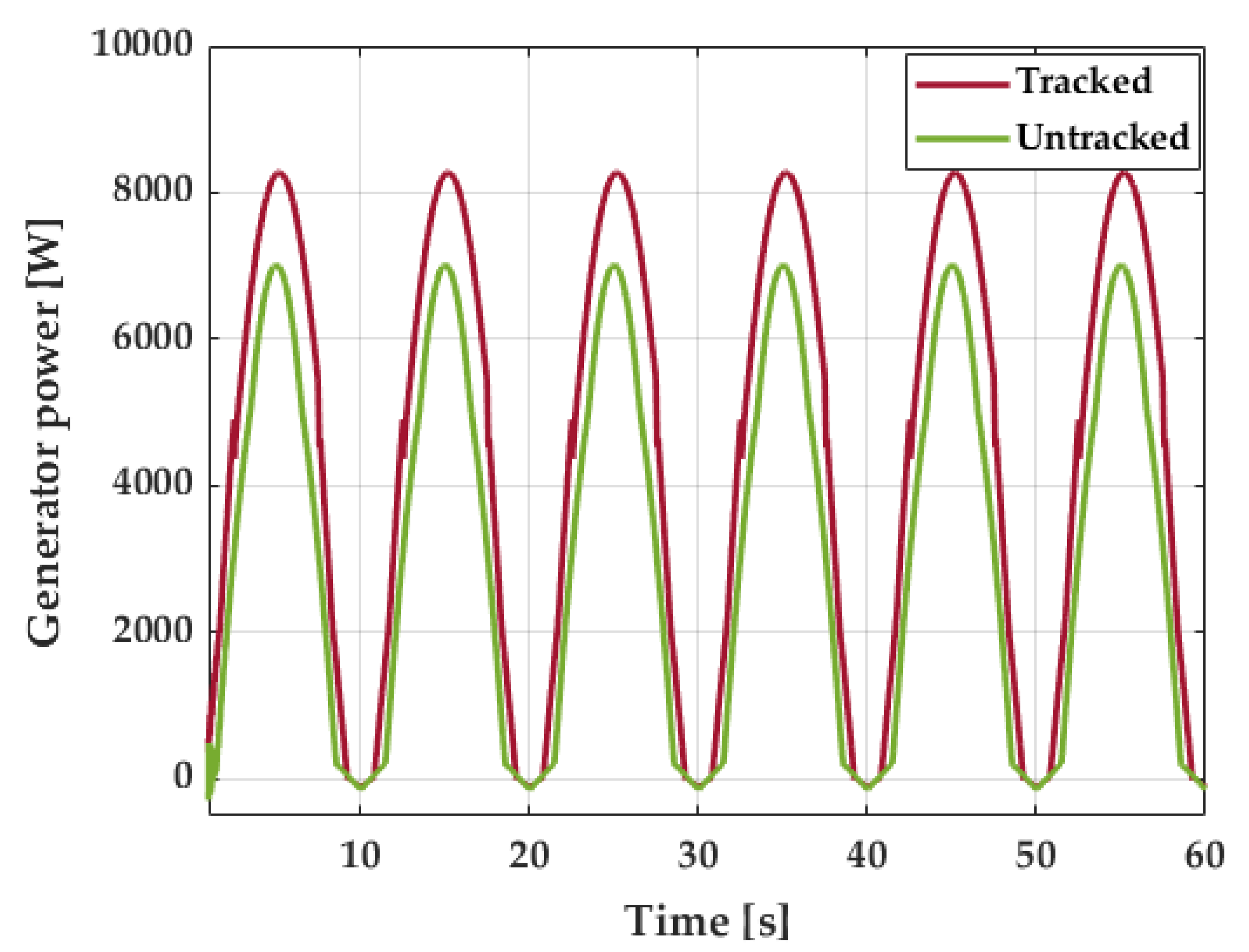
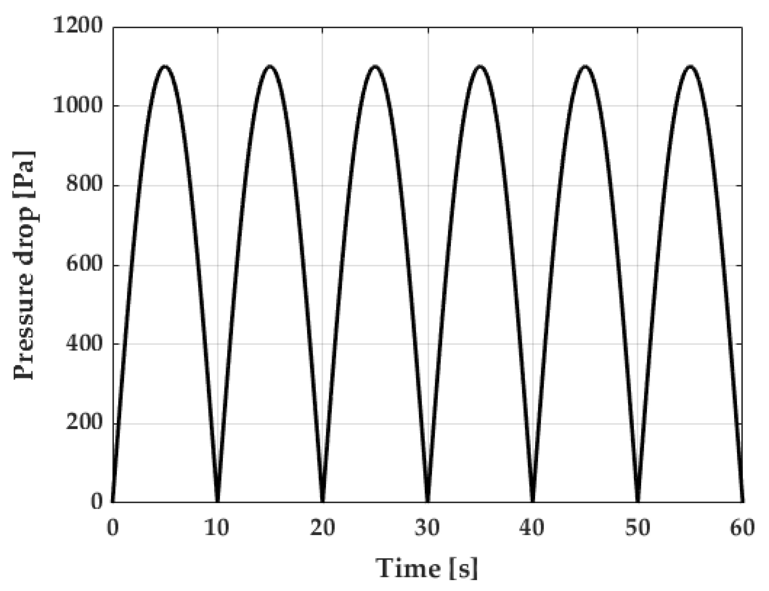
In the first case, the aim was to generate an environment where the flow coefficient is below 0.3; thus, the amplitude was settled at 750 Pa with a period of 10 s as it is displayed in Figure 7. Results were compared with a constant reference generator to display the main advantages of the combination between the FLC and the ARG. Figure 8 shows the generated power of the turbine at a point before the stalling in the mentioned contrast; the advantages of the proposed control structure by means of the power generated can be seen. While the untracked frame produced a mean of 3.03 kW, the tracked structure increased to 4.26 kW, which implies an increment of 40%.
The same behavior is shown in the flow coefficients of Figure 9. Since it was possible for this parameter to be preserved for a longer time at its reference of 0.29 with the implementation of the FLC and the reference tracker, previous improvement in terms of energy could be reflected.
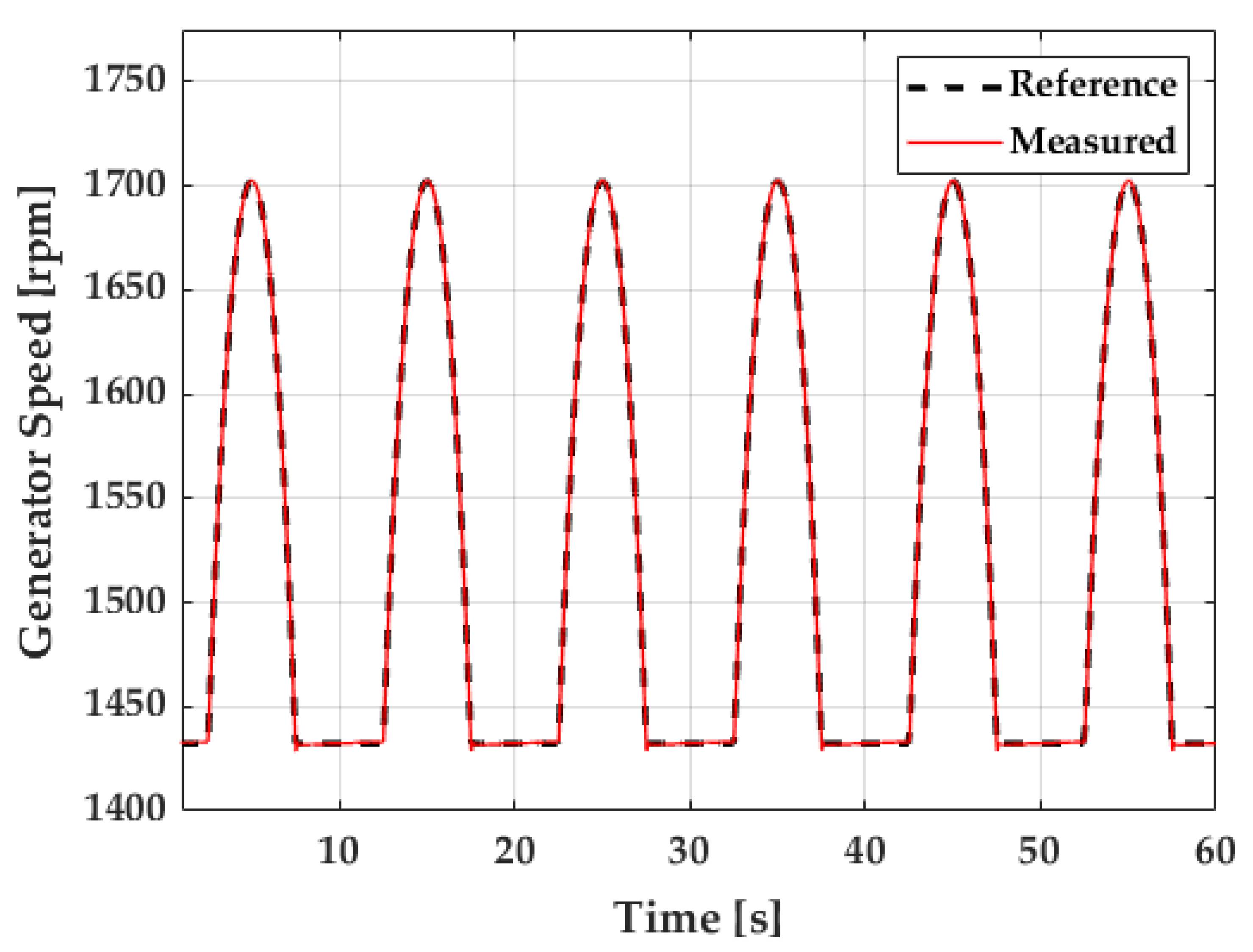
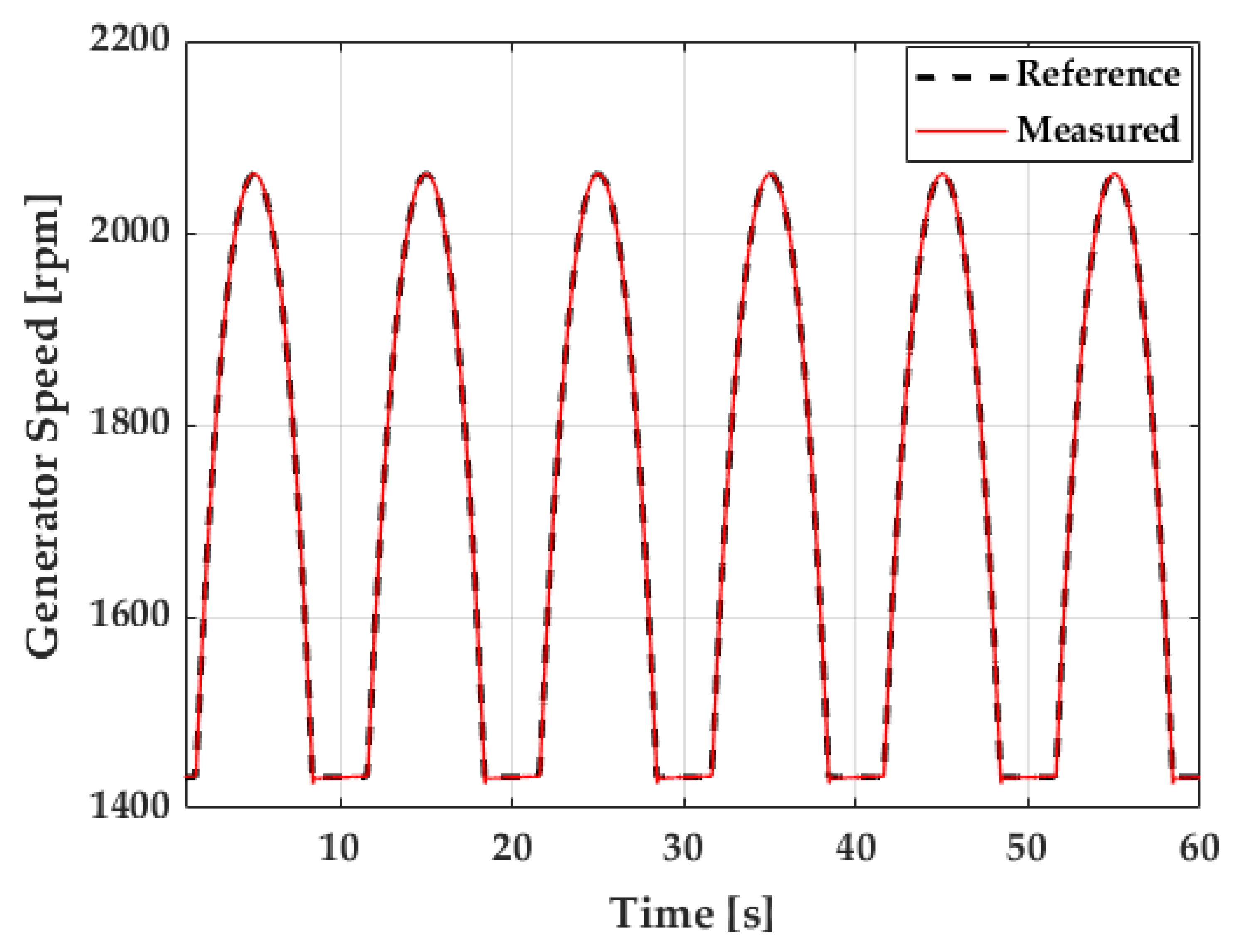
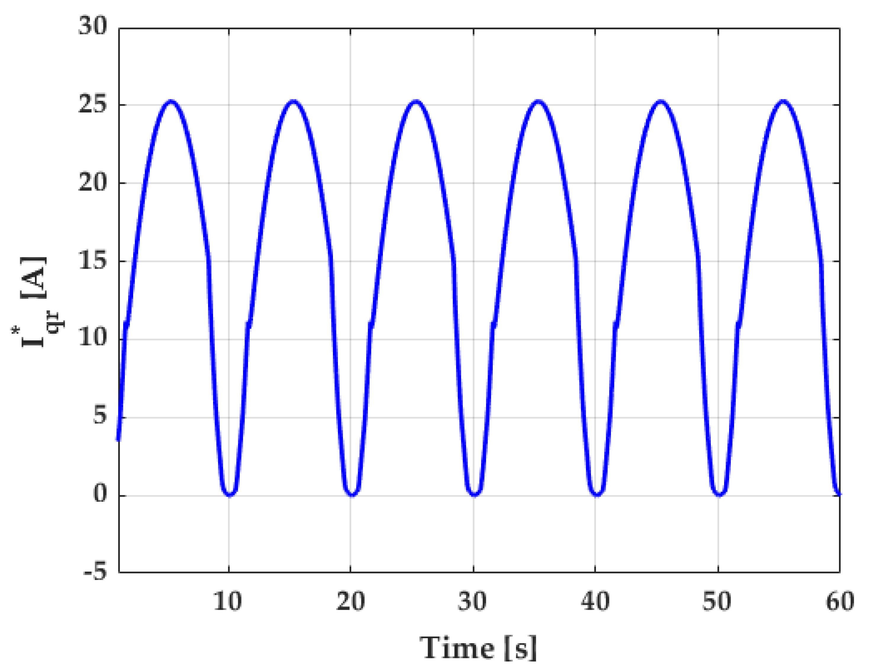
The controller capabilities are also possible to be shown at the velocity following, which is exposed in Figure 10. In this case, the behavior is acceptable since the configuration performed a suitable tracking even at drastic moments that occurred at lower limits or even at slope changes at the top of the curves. This suitable performance is also mirrored through the power increment as it provides the optimum flow coefficient, as it was previously explained. The control signal that is generated to follow the reference is exposed in Figure 11 where there is no saturation or drastic changes that can affect a real actuator.

3.2. Simulation Results at 1100 Pa

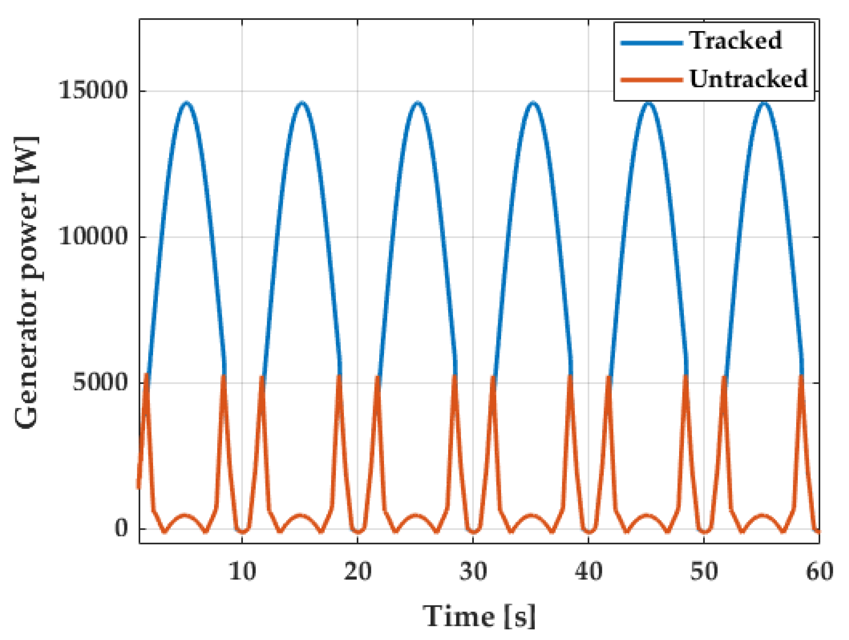
As an amplitude of 750 Pa is below the stalling point, another suitable comparison would be with a higher pressure so that this point is reached with a profile as Figure 12 exhibits. The following results were generated with an air pressure of the same period but with an amplitude of 1100 Pa that could drive the system to an unstable spot. In the same way, the power of the generator for the described situation is shown in Figure 13. At this case, the perception of enhancement is higher because the generated power with the advance structure overcomes the stalling. Actually, the mean of the power generated with a tracked reference is 7.9 kW, whereas the untracked produced a mean of 1 kW; this implies that the performance is almost eight times higher.
Figure 14 shows a reflection of the generated power previously described through the flow coefficient. The combination of FLC and ARG stayed at a value below 0.3, which increases the performance, whereas the untracked scenario exceeds this limit.
With regard to the controller, Figure 15 and Figure 16 expose the demeanor. It can be seen that the tracking performance is suitable like at 750 Pa because overshoots are imperceptible, and the speed is followed with a proper precision. The control signal that contributed to this behavior is also reasonable because saturations or noises are absent.

3.3. Simulation Results at Variable Pressure

Waves in the ocean are generally irregular and, for this case, a variable amplitude profile was generated with the same period as formerly presented, as Figure 17 unveils. The objective is to show the dynamical performance of the proposed scheme under variable air pressures. Figure 18, which shows the generated power, is also reflected with the flow coefficient from Figure 19. When the amplitude is high, the flow coefficient is limited below 0.3 and the power generated is maximum. As long as the amplitude is decreased, the flow coefficient stands less time at is maximum.
The reference tracking that is shown in Figure 20 provides an overview of generator speed at the different amplitudes. Between 27.5 and 52.5 s, the speed of the generator is leveled off as it reached the lower available limit. Lastly, the control signal of Figure 21 follows the trend of suitable behavior as previous cases.

4. Conclusions

In this study, an advance combination of FLC with ARG was designed and implemented in a simulation environment to increase the performance of an OWC system linked to a DFIG. These systems, which are used to transform kinetic wave energy into electrical, are commonly applied with constant reference tracking, but the employment of an ARG certainly showed significant improvements.
The research also focused on the avoidance of the stalling, a Wells turbine phenomenon that decays the system performance. The proposed structure displayed an increment of near 40% of output power when the system works with a flow coefficient value below 0.3 (near stalling). However, the major enhancement is generated when this value is above 0.3 as it was possible to achieve close to eight times more output power. Additionally, it was shown that, during these situations, the controller was able to track the desired speed with suitable demeanor and a satisfactory control signal. Finally, a further realistic situation was simulated with variable pressure amplitude where the outcomes still had a suitable behavior as the previous results.
Future research aims are intended to use type-2 FLC, which is known for its uncertainties handling capabilities. In this sense, the employment of idealized sine waves might not be the best option as real wave profiles can be used in order to achieve and tune the control robustness features. Other controllers such as neural PIDs deserve attention for the implementation in these systems. Regarding the reference generator, the usage of ANNs for an advance ARG is another suitable option with the employment of real data.

Author Contributions

Conceptualization, C.N., O.B., and J.A.C.; methodology, C.N. and O.B.; software, J.A.C.; validation, O.B. and C.N.; formal analysis, C.N. and O.B.; investigation, C.N. and O.B.; resources, M.D.; data curation, C.N. and P.A.; writing—original draft preparation, C.N.; writing—review and editing, C.N., O.B., and M.D.; visualization, C.N. and P.F.B.; supervision, O.B. and I.C.; project administration, O.B., P.A., and I.C.; funding acquisition, O.B. and I.C. All authors have read and agreed to the published version of the manuscript.

Funding

This research was funded by the Basque Government, through the project EKOHEGAZ (ELKARTEK KK-2021/00092), Diputación Foral de Álava (DFA) through the project CONAVANTER, and to the UPV/EHU through the project GIU20/063.

Institutional Review Board Statement

Not applicable.

Informed Consent Statement

Not applicable.

Acknowledgments

The authors wish to express their gratitude to the Basque Government, Diputación Foral de Álava (DFA) and UPV/EHU.

Conflicts of Interest

The authors declare no conflict of interest.

Abbreviations

The following abbreviations are used in this manuscript:
OWCOscillating water column
WTGWind turbine generator
DFIGDoubly-fed induction generator
VFCVoltage and frequency control
FCFull converter
PIDProportional-integral-derivative
FOPIDFractional order proportional-integral-derivative
SMCSliding mode control
ANNArtificial neural networks
FLCFuzzy logic control
ARGAirflow reference follower
NBNegative big
NMNegative medium
NSNegative small
ZZero
PSPositive small
PMPositive medium
PBPositive big
RSCRotor side converter
GSCGrid side converter
PWMPulse-width-modulation

References

  1. Lupíšek, A.; Trubačík, T.; Holub, P. Czech Building Stock: Renovation Wave Scenarios and Potential for CO2 Savings until 2050. Energies 2021, 14, 2455. [Google Scholar] [CrossRef]
  2. European Commission. Energy: Roadmap 2050, Impact Assesment and Scenario Analysis; The European Commission: Brussels, Belgium, 2011. [Google Scholar]
  3. International Energy Agency. Renewables 2020; Technical Report; International Energy Agency: Paris, France, 2020. [Google Scholar]
  4. Shehata, A.S.; Xiao, Q.; Saqr, K.M.; Alexander, D. Wells turbine for wave energy conversion: A review. Int. J. Energy Res. 2017, 41, 6–38. [Google Scholar] [CrossRef] [Green Version]
  5. Wan, C.; Yang, C.; Fang, Q.; You, Z.; Geng, J.; Wang, Y. Hydrodynamic Investigation of a Dual-Cylindrical OWC Wave Energy Converter Integrated into a Fixed Caisson Breakwater. Energies 2020, 13, 896. [Google Scholar] [CrossRef] [Green Version]
  6. Belibassakis, K.; Bonovas, M.; Rusu, E. A Novel Method for Estimating Wave Energy Converter Performance in Variable Bathymetry Regions and Applications. Energies 2018, 11, 2092. [Google Scholar] [CrossRef] [Green Version]
  7. Li, C.; Hang, Z.; Zhang, H.; Guo, Q.; Zhu, Y.; Terzija, V. Evaluation of DFIGs’ Primary Frequency Regulation Capability for Power Systems with High Penetration of Wind Power. Energies 2020, 13, 6178. [Google Scholar] [CrossRef]
  8. Pena, R.; Clare, J.; Asher, G. A doubly fed induction generator using back-to-back PWM converters supplying an isolated load from a variable speed wind turbine. Electr. Power Appl. IEE Proc. 1996, 143, 380–387. [Google Scholar] [CrossRef]
  9. Gomez, L.A.G.; Grilo, A.P.; Salles, M.B.C.; Sguarezi Filho, A.J. Combined Control of DFIG-Based Wind Turbine and Battery Energy Storage System for Frequency Response in Microgrids. Energies 2020, 13, 894. [Google Scholar] [CrossRef] [Green Version]
  10. Lu, K.H.; Hong, C.M.; Han, Z.; Yu, L. New Intelligent Control Strategy Hybrid Grey—RCMAC Algorithm for Ocean Wave Power Generation Systems. Energies 2020, 13, 241. [Google Scholar] [CrossRef] [Green Version]
  11. Pavel, C.C.; Lacal-Arántegui, R.; Marmier, A.; Schüler, D.; Tzimas, E.; Buchert, M.; Jenseit, W.; Blagoeva, D. Substitution strategies for reducing the use of rare earths in wind turbines. Resour. Policy 2017, 52, 349–357. [Google Scholar] [CrossRef]
  12. Mishra, S.K.; Mohanta, D.K.; Appasani, B.; Kabalci, E. OWC-Based Ocean Wave Energy Plants; Springer: Singapore, 2021. [Google Scholar] [CrossRef]
  13. Lekube, J.; Garrido, A.J.; Garrido, I.; Otaola, E.; Maseda, J. Flow Control in Wells Turbines for Harnessing Maximum Wave Power. Sensors 2018, 18, 535. [Google Scholar] [CrossRef] [PubMed] [Green Version]
  14. Barambones, O.; Cortajarena, J.A.; Gonzalez de Durana, J.M.; Alkorta, P. A real time sliding mode control for a wave energy converter based on a wells turbine. Ocean Eng. 2018, 163, 275–287. [Google Scholar] [CrossRef]
  15. Jayashankar, V.; Udayakumar, K.; Karthikeyan, B.; Manivannan, K.; Venkatraman, N.; Rangaprasad, S. Maximizing power output from a wave energy plant. In Proceedings of the 2000 IEEE Power Engineering Society Winter Meeting, Singapore, 23–27 January 2000; Volume 3, pp. 1796–1801. [Google Scholar] [CrossRef]
  16. Oshnoei, A.; Khezri, R.; Muyeen, S.; Blaabjerg, F. On the Contribution of Wind Farms in Automatic Generation Control: Review and New Control Approach. Appl. Sci. 2018, 8, 1848. [Google Scholar] [CrossRef] [Green Version]
  17. Tepljakov, A.; Alagoz, B.B.; Yeroglu, C.; Gonzalez, E.A.; Hosseinnia, S.H.; Petlenkov, E.; Ates, A.; Cech, M. Towards Industrialization of FOPID Controllers: A Survey on Milestones of Fractional-Order Control and Pathways for Future Developments. IEEE Access 2021, 9, 21016–21042. [Google Scholar] [CrossRef]
  18. Fragoso, S.; Garrido, J.; Vázquez, F.; Morilla, F. Comparative Analysis of Decoupling Control Methodologies and H infinity Multivariable Robust Control for Variable-Speed, Variable-Pitch Wind Turbines: Application to a Lab-Scale Wind Turbine. Sustainability 2017, 9, 713. [Google Scholar] [CrossRef] [Green Version]
  19. Xiong, L.; Li, P.; Li, H.; Wang, J. Sliding Mode Control of DFIG Wind Turbines with a Fast Exponential Reaching Law. Energies 2017, 10, 1788. [Google Scholar] [CrossRef] [Green Version]
  20. Utkin, V.; Lee, H. Chattering Problem in Sliding Mode Control Systems. IFAC Proc. Vol. 2006, 39, 1. [Google Scholar] [CrossRef]
  21. Chien, T.H.; Huang, Y.C.; Hsu, Y.Y. Neural Network-Based Supplementary Frequency Controller for a DFIG Wind Farm. Energies 2020, 13, 5320. [Google Scholar] [CrossRef]
  22. Cifuentes, J.; Marulanda, G.; Bello, A.; Reneses, J. Air Temperature Forecasting Using Machine Learning Techniques: A Review. Energies 2020, 13, 4215. [Google Scholar] [CrossRef]
  23. Hosseinzadeh, M.; Sadati, N.; Zamani, I. H infinity disturbance attenuation of fuzzy large-scale systems. In Proceedings of the 2011 IEEE International Conference on Fuzzy Systems (FUZZ-IEEE 2011), Taipei, Taiwan, 27–30 June 2011; pp. 2364–2368. [Google Scholar] [CrossRef]
  24. Sałabun, W.; Więckowski, J.; Shekhovtsov, A.; Palczewski, K.; Jaszczak, S.; Wątróbski, J. How to Apply Fuzzy MISO PID in the Industry? An Empirical Study Case on Simulation of Crane Relocating Containers. Electronics 2020, 9, 2017. [Google Scholar] [CrossRef]
  25. Tao, C.W.; Taur, J.S. Robust fuzzy control for a plant with fuzzy linear model. IEEE Trans. Fuzzy Syst. 2005, 13, 30–41. [Google Scholar] [CrossRef]
  26. Coleman, C.P.; Godbole, D. A comparison of robustness: Fuzzy logic, PID, and sliding mode control. In Proceedings of the 1994 IEEE 3rd International Fuzzy Systems Conference, Orlando, FL, USA, 26–29 June 1994; pp. 1654–1659. [Google Scholar] [CrossRef]
  27. Gerlach, L.; Bocklisch, T. Experts versus Algorithms? Optimized Fuzzy Logic Energy Management of Autonomous PV Hybrid Systems with Battery and H2 Storage. Energies 2021, 14, 1777. [Google Scholar] [CrossRef]
  28. Napole, C.; Barambones, O.; Calvo, I.; Derbeli, M.; Silaa, M.Y.; Velasco, J. Advances in Tracking Control for Piezoelectric Actuators Using Fuzzy Logic and Hammerstein-Wiener Compensation. Mathematics 2020, 8, 2071. [Google Scholar] [CrossRef]
  29. Alberdi, M.; Amundarain, M.; Maseda, F.J.; Barambones, O. Stalling behavior improvement by appropriately choosing the rotor resistance value in wave power generation plants. In Proceedings of the 2009 International Conference on Clean Electrical Power, Capri, Italy, 9–11 June 2009; pp. 64–67. [Google Scholar] [CrossRef]
  30. Barambones, O.; Gonzalez de Durana, J.; Calvo, I. Adaptive Sliding Mode Control for a Double Fed Induction Generator Used in an Oscillating Water Column System. Energies 2018, 11, 2939. [Google Scholar] [CrossRef] [Green Version]
  31. Sarmento, A.J.N.A.; Gato, L.M.C.; Falcao, A.D.O. Turbine-controlled wave energy absorption by oscillating water column devices. Ocean Eng. 1990, 17, 481–497. [Google Scholar] [CrossRef]
  32. Barambones, O.; De La Sent, M.; Alkorta, P. A robust control of double-feed induction generator for wind power generation. In Proceedings of the 2009 35th Annual Conference of IEEE Industrial Electronics, Porto, Portugal, 3–5 November 2009; pp. 94–99. [Google Scholar] [CrossRef]
  33. Fletcher, J.; Yang, J. Introduction to the Doubly-Fed Induction Generator for Wind Power Applications. In Paths to Sustainable Energy; Nathwani, J., Ng, A., Eds.; IntechOpen: Rijeka, Croatia, 2010; Chapter 14. [Google Scholar] [CrossRef] [Green Version]
  34. Mendel, J. Type-1 Fuzzy Systems: Design Methods and Applications. In Uncertain Rule-Based Fuzzy Logic Systems: Introduction and New Directions; Springer International Publishing: Cham, Switzerland, 2003; Chapter 4; pp. 229–234. [Google Scholar] [CrossRef]
  35. Liang, Y.; He, Y.; Niu, Y. Microgrid Frequency Fluctuation Attenuation Using Improved Fuzzy Adaptive Damping-Based VSG Considering Dynamics and Allowable Deviation. Energies 2020, 13, 4885. [Google Scholar] [CrossRef]
  36. Khudoyberdiev, A.; Ahmad, S.; Ullah, I.; Kim, D. An Optimization Scheme Based on Fuzzy Logic Control for Efficient Energy Consumption in Hydroponics Environment. Energies 2020, 13, 289. [Google Scholar] [CrossRef] [Green Version]
  37. Sheng, W.; Li, H. A Method for Energy and Resource Assessment of Waves in Finite Water Depths. Energies 2017, 10, 460. [Google Scholar] [CrossRef] [Green Version]
  38. Medeiros, A.; Ramos, T.; de Oliveira, J.T.; Medeiros Júnior, M.F. Direct Voltage Control of a Doubly Fed Induction Generator by Means of Optimal Strategy. Energies 2020, 13, 770. [Google Scholar] [CrossRef] [Green Version]
  39. Martinez, M.I.; Tapia, G.; Susperregui, A.; Camblong, H. Sliding-Mode Control for DFIG Rotor- and Grid-Side Converters Under Unbalanced and Harmonically Distorted Grid Voltage. IEEE Trans. Energy Convers. 2012, 27, 328–339. [Google Scholar] [CrossRef]
  40. Wu, Z.; Zhu, C.; Hu, M. Improved Control Strategy for DFIG Wind Turbines for Low Voltage Ride Through. Energies 2013, 6, 1181–1197. [Google Scholar] [CrossRef] [Green Version]
  41. Pang, B.; Dai, H.; Li, F.; Nian, H. Coordinated Control of RSC and GSC for DFIG System under Harmonically Distorted Grid Considering Inter-Harmonics. Energies 2020, 13, 28. [Google Scholar] [CrossRef] [Green Version]
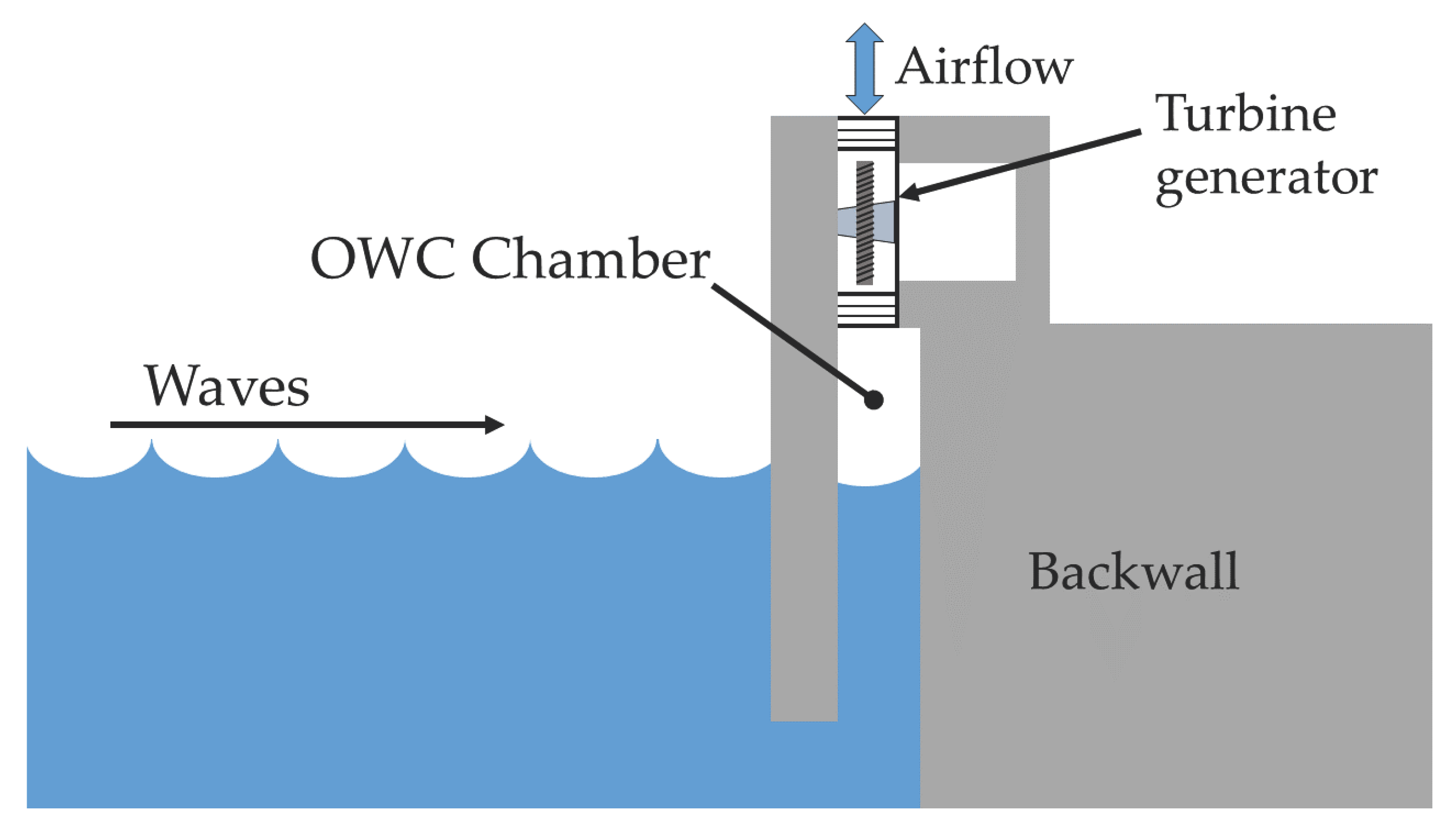
Figure 1. Schematic graphic description of an OWC.
Energies 14 03499 g001
Figure 2. Relation between torque and flow coefficient.
Energies 14 03499 g002
Figure 3. FLC structure.
Energies 14 03499 g003
Figure 4. Membership input functions of the implemented FLC.
Energies 14 03499 g004
Figure 5. FLC control surface.
Energies 14 03499 g005
Figure 6. Diagram of the OWC system with its DFIG and control structure.
Energies 14 03499 g006
Figure 7. Low pressure drop profile at 750 Pa.
Energies 14 03499 g007
Figure 8. Generated power at 750 Pa with and without reference tracking.
Energies 14 03499 g008
Figure 9. Flow coefficient at 750 Pa with and without reference tracking.
Energies 14 03499 g009
Figure 10. Reference following at 750 Pa.
Energies 14 03499 g010
Figure 11. Current at 750 Pa.
Energies 14 03499 g011
Figure 12. High pressure drop profile at 1100 Pa.
Energies 14 03499 g012
Figure 13. Generated power at 1100 Pa with and without reference tracking.
Energies 14 03499 g013
Figure 14. Flow coefficient at 1100 Pa with and without reference tracking.
Energies 14 03499 g014
Figure 15. Reference following at 1100 Pa.
Energies 14 03499 g015
Figure 16. Current at 1100 Pa.
Energies 14 03499 g016
Figure 17. Variable pressure drop profile.
Energies 14 03499 g017
Figure 18. Generated power at variable pressure with reference tracking.
Energies 14 03499 g018
Figure 19. Flow coefficient at variable pressure with reference tracking.
Energies 14 03499 g019
Figure 20. Reference following at variable pressure.
Energies 14 03499 g020
Figure 21. Current at variable pressure.
Energies 14 03499 g021
Table 1. FLC linguistic rules.
E∖ E ˙ NBNSZPSPB
NBNBNMNMNSZ
NSNMNMNSZZ
ZNMNSZPSPM
PSZZPSPMPM
PBZPSPMPMPB
Table 2. Wells turbine parameters.
PropertiesValuesUnits
Number of blades8-
Turbine torque coefficient0.7079 kg · m
Turbine radius0.7285m
Cross-sectional area1.1763 m 2
Blade height0.4m
Chord length0.38m
Table 3. DFIG technical properties.
PropertiesValuesUnits
Stator voltage380V
Rotor voltage190V
Rated stator current18V
Rated rotor current24A
Rated speed1447 at 50 Hzr.p.m.
Rated torque50Nm
Stator resistance0.275 Ω
Rotor resistance0.325 Ω
Magnetizing inductance0.0664H
Stator leakage inductance0.00264H
Rotor leakage inductance0.00372H
Inertia moment0.07kg · m 2
Publisher’s Note: MDPI stays neutral with regard to jurisdictional claims in published maps and institutional affiliations.