1. Introduction
Solar energy, wind energy, and tidal and biomass energy, as the main forms of clean energy technologies, have become the true solution to the recent energy crisis worldwide. Natural energy sources, such as coal, oil, natural gas, and nuclear materials, are limited and cause pollution, and thus, to meet the dramatically increasing demand for energy, clean and renewable energy technologies, such as wind and photovoltaic (PV) energy, have been widely deployed over recent decades [
1,
2]. Renewable energy systems will herald the most substantial advances in energy efficiency, energy saving, and environmental protection over the next few decades [
3]. Grid-connected renewable energy systems are usually a more suitable choice for locations near a power grid because energy storage systems are currently unsatisfactory. Wind and PV energies complement each other because sunny days are often calm and heavy winds usually arise at night or on overclouded days. The combination of the PV module and wind energy module will reduce the zero-power periods. Therefore, solar/fuel cell/wind hybrid generation systems have a higher obtainability to supply continuous electrical energy than any other single source. In recent years, there has been a large focus on developing renewable energy applications. While significant improvements have been made in renewable energy applications, there are some essential limitations in these applications. Owing to these limitations, solar and wind energy systems are intermittent natural sources. Moreover, the dynamics of the electrochemical reaction of a fuel cell are quite slow compared to the electrical load. This is unacceptable for recent power systems that require a constant voltage and a constant frequency voltage source.
Distributed generation (DG) units are small-scale electrical power supplies connected together in a microgrid [
2]. DG units based on renewable energy resources, such as solar, wind, and biomass, have been widely deployed owing to their numerous advantages. DG technologies can offer customers with energy needs that are environmentally friendly, more cost-effective, and provide higher energy reliability and power quality than traditional solutions. The DG provides electrical power at locations closer to customers than a central generation plant. Hence, implementing DG units in electric distribution systems is one of the key solutions for supplying electrical power to consumers. Another benefit of DG is that it can reduce the peak load demand and total charges of energy usage, as well as guarantee better power quality and reliability. The DG power rating ranges from a few kilowatts to 50 MW.
Hybrid distributed generation systems (HDGs) are a good solution for regions with traditional energy shortages aiming to adopt solar/fuel cell/wind energy in DG systems, which take advantage of both DG systems and renewable energy systems. To install such a hybrid renewable energy system, a two-input single-output scheme has been developed in several studies [
4,
5]. Multi-input DC-DC power converter topologies are used to accommodate the variations in hybrid renewable energy, allowing power to be transferred from different input voltage sources to the output. As described in [
4], a single-input, dual-input converter was developed for a combined solar/wind energy generation system. Both the PV array and wind turbine were utilized. In [
5], a high-frequency transformer (HFT) was utilized to achieve an electrical or galvanic isolation advantage. In addition, a full-bridge dual-input DC-DC power converter with variable pulse-width-modulated (PWM) control can be realized to provide a potential approach to integrating power from diverse sources into a high-frequency-link isolated circuit. However, these circuits cannot be connected to backup power banks (utility or batteries). Hence, they are unsuitable for DG PV panels/fuel cells/wind turbine hybrid generation systems.
In many applications, it is necessary to associate several renewable energy sources of dissimilar types (e.g., solar PV and wind) and integrate them into a microgrid [
6,
7,
8,
9,
10,
11]. Multi-port DC-DC power converters are proposed to apply efficient power management and grid integration for multiple sources. This work proposes a new power converter circuit that can overcome the problems of intermittent features and the slow response of renewable energy sources. The proposed converter topology integrates several renewable energy sources in addition to energy storage units. The effect of the intermittent nature can be greatly minimized by integrating renewable energy sources. These sources compensate for each other. However, this integration increases the reliability and obtainability of the entire system. Furthermore, integrating the energy storage overcomes the slow response problem of renewable sources. Thus, an energy storage unit can offer the additional energy required by the load or utilize the excess energy delivered by the renewable sources. This will significantly improve the dynamics of the overall system.
Figure 1 shows a multisource, grid-connected, two-stage, hybrid renewable energy system composed of a multi-port DC-DC power converter and a PWM DC-AC power inverter [
12]. The DC-DC converter connects several sources, such as photovoltaic (PV) modules, fuel cells (FCs), and wind turbine generators (WTGs), to multiple input ports. The multi-port DC-DC power converter not only adjusts the DC output of the sources to a regulated DC voltage required for inverter input, it can also afford several essential control functions, such as tracking the maximum power point (MPPT), for different renewable sources. Some of the necessary design considerations and key advantages of the proposed system are as follows:
- #
Lightweight and compact size.
- #
Enhanced efficiency and high reliability.
- #
Effective utilization of wind and solar PV energy.
- #
The capability of integrating various sources.
- #
Delivery of an alternative power source for loads when the power delivered by local generators cannot fulfill the microgrid load.
The remainder of this paper is organized as follows. Afterward, a survey of previous studies is introduced to the multiport DC-DC power converter described in
Section 1. The proposed converter topology and operation principle are analyzed in
Section 2. The control strategy for the proposed multiport DC-DC power converter is described in
Section 3. In
Section 4, a dynamic simulation model of the multiport DC-DC power converter is formulated and implemented in a MATLAB/Simulink environment (Version R2018b, Natick, Massachusetts, USA), using the design concerns for the studied converter. The experimental results are presented in
Section 5 to verify the effectiveness of the treated multi-port DC-DC power converter for simultaneous MPPT control of hybrid PV panels/fuel cells/wind turbine systems.
Section 6 summarizes this study with certain concluding observations.
The main contribution of the manuscript
- #
A multi-port DC-DC power converter is proposed for the integration of three renewable energy sources (PV panels, fuel cells, and wind turbines) and an energy storage source (batteries or supercapacitors).
- #
An energy management system was developed.
- #
A simulation model was proposed for energy management strategy to achieve an efficient power utilization.
- #
The battery energy storage compensates for the slow response of the fuel cells and photovoltaic units.
- #
The proposed strategy can share power between DG units, even under a different renewable power generation.
- #
An experimental prototype was applied to verify the effectiveness of the proposed multi-port converter topology.
2. Proposed Converter and Operation Principle
A new multi-port DC-DC power converter is proposed for the integrated power management of many renewable energy sources, and consists of PV panels, fuel cells, and a wind turbine hybrid generation system, in which only one switch is used for each input port connected to a source, as shown in
Figure 2. This first converter cell comprises a boost inductor
L1, an active switch
S1, a diode
D1, and a filtering capacitor
Cdc at the output, as shown in
Figure 2.
Figure 2 presents the circuit diagram of the proposed multi-port DC-DC power converter, and the given parameters of the circuit are shown in
Table 1. This converter circuit is composed of three ports in parallel, in addition to a battery bank, as an energy storage unit. Each port comprises a semiconductor power switch, power diode, and boost inductor. However, the proposed multiport DC-DC converter circuit has the fewest number of components, and hence, a proper cost as compared with the present multi-port DC-DC power converter circuits [
13,
14,
15,
16,
17,
18,
19,
20].
2.1. Driving Signal Scheme
Figure 3 schematically shows the gate-pulse control signals of the
S1,
S2, and
S3 main switches of the proposed converter (
Figure 2). The implementation of an N-parallel-cell converter was studied. If the parallel cells are controlled using a synchronous clock, as displayed in
Figure 3a for a three-parallel-cell system, this system achieves a performance close to that of a single high-power converter. However, if these cells are controlled individually and, hence, clocked at different switching frequencies, as illustrated in
Figure 3b, the current ripples in the converter output and input will be considerably minimized owing to a passive ripple cancelation that arises among the cells.
The well-known interleaving clocking method is illustrated in
Figure 3c. To interleave N parallel-connected (or series-connected) converter cells, active switches are switched at the same frequency as the switching operation, but pulses are phase-shifted by 2π/N radians [
21]. The proposed converter can be boosted by turning on the active switch of any particular cell (
S1,
S2, or
S3) simultaneously.
In the interleaved clocking technique, all cells are switched on and off at the same frequency, while operation waveforms shift in phase during the switching cycle. The advantages of this technique include a harmonic reduction among the cells and a higher ripple frequency and lower ripple amplitude in the input and output waveforms, which are easy to filter [
21]. For a wide class of converter topologies, the N-cell interleaving clocking yields an N-fold increase in the ripple current fundamental frequency and a magnitude decrease in the peak ripples by a factor of N or more when compared with synchronized clocking [
22,
23,
24,
25].
2.2. Steady-State Analysis of the Studied Converter
The integrated converter circuit has three operation intervals: in the first interval, all switches are turned on; in the second interval, the active switch
Q1 is turned off while at least one of the other active switches is on; and in the third interval, all active switches are turned off.
Figure 3c shows the steady-state voltage and current waveforms of the converter during one switching cycle covering the three operating intervals.
Under operation mode 1, t ∈ [t0–t2, t3–t5, t6–t8], during which all of the switches are on and the inductors L1, L2, and L3 store the extracted energy from the energy sources, whereas the energy stored in the batteries in the preceding switching cycle is supplied to the grid through diodes Dq1, Dq2, and Dq3.
Under operation mode 2, t ∈ [t0–t1, t3–t4, t6–t7], during which S1 is turned off and at least one switch Sn (n = 2, 3..., or m) is turned on. There are 2m−1 − 1 different cases in this mode subject to the situations of the other (m − 2) switching devices S2..., Sn−1, Sn+1,..., Sm. One case is explained as an example, in which only one switch Sn is turned on and all other switching devices are turned off.
Under operation mode 3, t ∈ [t2–t3, t5–t6, t8–t9], during which all switches are off.
3. Control Strategy
The proposed converter has four ports, three of which are inputs consisting of PV panels, fuel cells, wind turbines, and a two-way battery storage port, as shown in
Figure 4. The system uses three main switches through which zero-voltage switching is achieved. A unidirectional multiport boost DC-DC converter links the PV, FC, and WT with the DC-link, maintaining the stability of the converter system even with fluctuations in the load [
26,
27,
28]. The energy can flow in only one direction from the PV, FC, and WT to the DC link. Using an appropriately designed MPPT algorithm, the PV, FC, and WT can be regulated to deliver maximum obtainable power from sunlight or wind using the studied converter. In the battery case, a bidirectional DC-DC converter is connected to the DC link and used as a battery charge regulator. The SOC battery charge is maintained around its reference value to obtain a high charging efficiency.
This converter applies multiple functions: it acts as a regulator for charging the battery in a grid-connected operation and as a boost converter to deliver energy from the batteries to the microgrid when there is insufficient power from the solar cell sources, fuel cells, and wind turbines to feed the local loads during an island operation.
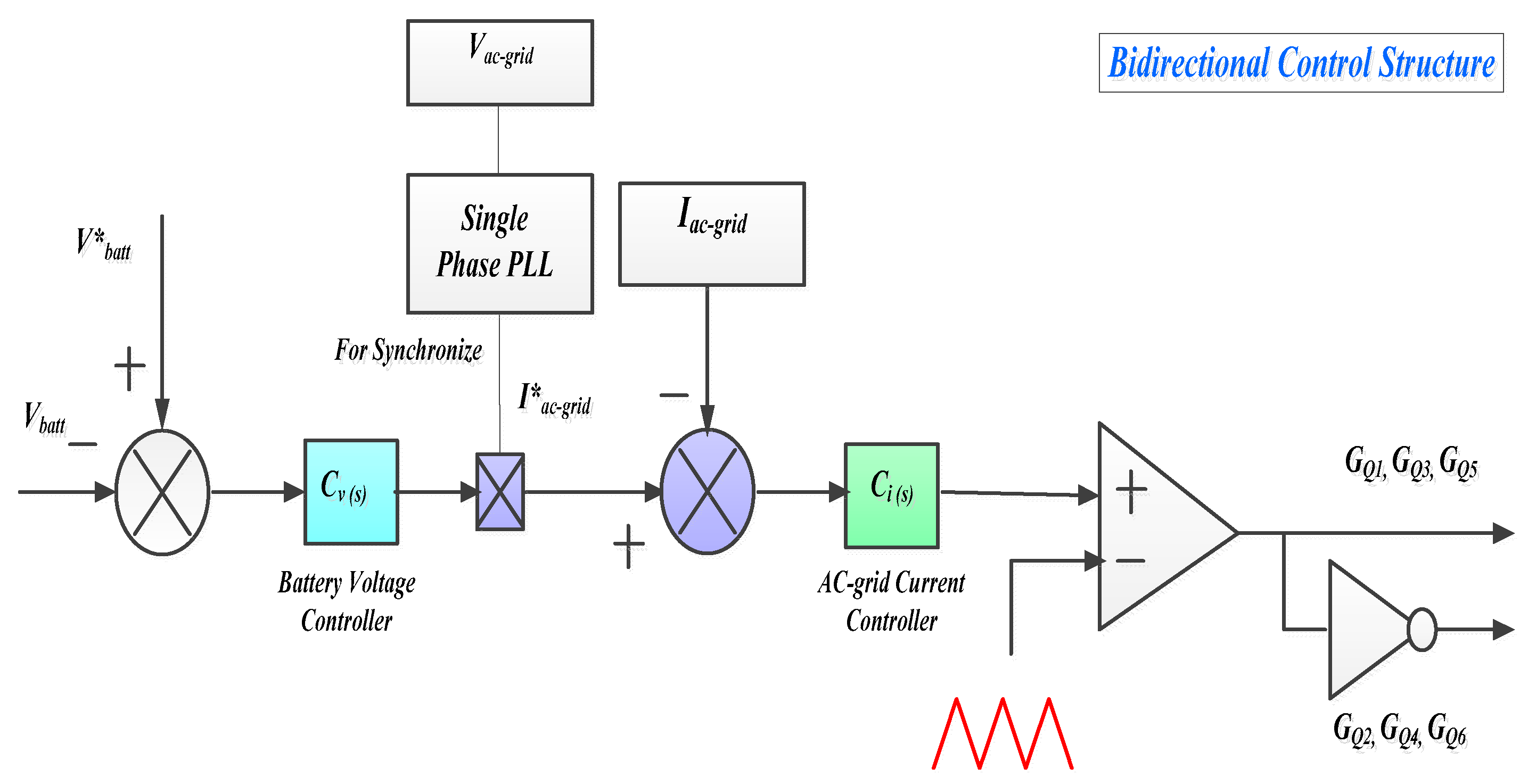
Figure 5 shows a simplified bidirectional control structure. In order to reduce the switching loss and conduct a loss of IGBTs, the one-leg shoot-through procedure was chosen in the modulation strategy. The control strategy of the system is presented, as displayed in
Figure 5, to deal with versatile load fluctuations.
In
Figure 5, the output voltage is regulated using the
Cv(s) regulator and is limited to a safe value generating the amplitude of input reference current. However, this reference signal is then multiplied with the output of the phase-locked-loop to synchronize the reference with the AC grid voltage. The inductor currents are required to follow its reference current using a current regulator
Ci(s), which produces suitable gateway signals. The major advantage of this controller is that it has a constant switching frequency.
3.1. PV Control Design for a Multiport DC-DC Converter
The MPPT methods differ according to the DC-DC converter topology and the related circuit parameters [
29,
30,
31]. The panel voltage
Vpv is sensed along with the PV input current
Ipv before the input capacitance
Cs. The MPPT algorithm uses these two values to track the MPP under different temperatures and irradiance levels. The reference point of the panel input is calculated and maintained at the MPP value, as shown in
Figure 6. The MPPT is attained using a voltage loop (outer loop) and a current loop (inner loop), as shown in
Figure 4. By increasing the current reference of the multiport converter, the output voltage decreases. Therefore, the signs of the voltage reference compensator and feedback are reversed. To avoid the output voltage from increasing higher than the component rating, the voltage feedback is planned for the internal comparators, which can make a cycle-by-cycle trip of the PWM during an overvoltage state. The I-V and P-V curves at different cell temperatures and a constant irradiation level can be obtained by measuring the PV voltage, current, and output power, as shown in
Figure 6.
The values of open-circuit voltage
Voc and current of short-circuit
Isc related to the studied PV array are given in terms of the number of series and parallel cells:
The current versus voltage (I-V) characteristics of the PV panel can be expressed as follows [
26,
27]:
Equation (3) can be used for a particular level of insolation
Sn and at a specific operating temperature
Tc of the PV cell.
3.2. FC Control Design for a Multiport DC-DC Converter
The control of the proposed converter comprises output-voltage stabilizing and current-limiting functions. A typical control is shown in
Figure 4. The current limit is set at a stable level; however, for diverse sources, it can be adapted (e.g., for fuel cells, it should be proportionate to the
H2 fuel-injection, owing to the fuel cell characteristics), as shown in
Figure 7. The current limit of the boost converter was adjusted to 30 A during the simulation tests. The DC voltage reference is also set to the fixed value required by the energy source integrated inverter with a microgrid or load. The energy excess or shortage can be determined from the reference value deviation. However, a power management system uses the deviation as an indicator of such situations. The voltage reference in this control strategy is the maximum value. When the DC voltage is higher than the reference value, this causes a decrease in the inductor current. When the battery SOC is lower than the reference value, the fuel cell supplies nearly the total power to the load. The implementation of this method is simple in comparison with the preceding schemes. Therefore, the PI controller gains are tuned online to improve the response.
3.3. WT Control Design for Multiport DC-DC Converter
The MPPs of the wind generator were estimated using the measured wind speeds. However, the other parameters are given by the manufacturer as follows:
where
PMPP is the maximum power extracted from the wind turbine;
vwind is the wind speed, which can be measured using an anemometer;
r is the radius of the wind turbine rotor plane;
ρ is the air density;
vcut_in,
vnorm, and
vcut_out are the cut-in, rated, and cut-out wind speeds of the wind turbine, respectively;
Pnorm is the rated power of the wind turbine, the value of which is equal to 60 kW; and
Cp is the wind turbine power coefficient. According to Betz’s law, the maximum value of the power coefficient
Cp is 0.59. Conferring to the wind turbine characteristics (power-wind speed curves) given by the manufacturer, when the average wind speed is about 13.4 m/h, the monthly produced energy of the selected wind turbine is 60 kWh. Consequently, the maximum value of
Cp was estimated to be 0.4457 for this wind turbine.
3.4. Battery Control Design
In this study, the power management in a microgrid is improved by the inclusion of backup energy storage, which consists of a set of batteries connected to a DC link through a bidirectional power converter. The bidirectional converter is composed of a boost inductor with inductance
L, two switches (
S1 and
S2) allowing the bidirectional current flow, and an output filtering capacitor
Cdc, as shown in
Figure 8. With the power management method, there are two blocks used for controlling the voltage with suitable limitation blocks to achieve the required energy flow under different conditions. These controllers produce the current reference for the energy storage unit. The first controller adjusts the DC-link voltage and the second control block regulates the battery charge.
It is not advisable to discharge the energy storage battery deeply. However, at a low voltage level of the energy storage, there is a limited range of charging energies. This causes an over-voltage in the DC link during an energy recovery from the load side. For electrochemical batteries, the battery life has a limited range of discharge cycles, and the battery must be protected.
4. Simulation Results
Detailed simulation models were developed in a Simulink/MATLAB environment to verify the multi-port DC-DC power converter. These models present an alternative emergency power source established by fuel cells and lithium-ion batteries. An energy management system is included in the simulation model, which is suitable for many renewable energy sources. Simulation results were obtained according to the usual daily load profile of a commercial building in Majmaah city, as shown in
Figure 9. The parameters of the proposed system are listed in
Table 2. The parameters and technical specifications of the simulated PV Panels, PEM Fuel Cell, and wind turbine are listed in
Appendix A (
Table A1,
Table A2 and
Table A3 respectively). The Simulink model of the proposed multiport DC-DC power converter is displayed in
Figure 10.
The MPPT control is utilized in the proposed converter to control the power produced by the PV panels, fuel cells, and wind turbine hybrid generation system, as shown in
Figure 10. The controller is based on the P&O MPPT control technique [
32,
33,
34,
35] to make the best use of the power delivered from PV panels, fuel cells, and wind turbines simultaneously under different weather conditions. However, the wind speed changes more severely than the solar insolation and temperature. The output voltage and current of each renewable source are used by the MPPT controller as an input to produce a proper pulse-width modulated control signal for the corresponding active switch, as shown in
Figure 10. A flowchart of the P&O MPPT algorithm is shown in
Figure 11, where
Ps(k) is the power of each source at the
kth step. For example, weather data such as solar insolation and ambient temperature are provided for calculating the quantity of energy that can be produced by solar PV panels. The PV output power value (
Ppv) is compared with the power consumed by the load (
PL) to determine the energy flow distribution between the energy storage system and the load. The extra photovoltaic energy is stored in the energy storage unit (batteries) by a bidirectional DC-DC converter (
Pbatt). A flowchart of the control scheme for the PV/FC/WT hybrid generation system is shown in
Figure 11. The control scheme can be divided into three cases as follows:
Case 1: Ppv > PL, and thus Pb = Ppv − PL. If the solar insolation value is satisfactorily high, the solar PV array supplies the load, and the surplus power is stored in the ESU (batteries) by the bidirectional DC-DC power converter.
Case 2: Ppv < PL and PL − Ppv ≤ Pfc, and thus, PL − Ppv = Pfc. That is, if the PV source cannot supply the load, then the load is powered directly from the solar PV panel and the fuel cell is turned on.
Case 3: Ppv < PL and PL − Ppv > Pfc, and thus, PL = Pfc = 0 and Pwt = Ppv. In this case, the solar PV panel cannot empower the load, the fuel cell is turned off, and the load is supplied directly from the wind turbine generator, according to the conditions in Case 1 or 2.
Simulations were simulated for 25 s to validate the transient system behavior using a proportional-integral (PI) controller.
Figure 12 shows the PV voltage and current. The PV power plant generation is regulated at the MPPT, which is proportional to the irradiance. The weather data were solar radiation (W/m
2), ambient temperature (°C), and wind speed (m/h). Typical weather data were collected during 1-h intervals. There are numerous meteorological software packages that can calculate the solar insolation level, ambient temperature, and wind speed. The microgrid power generation reference is set to one real power step (at 25 s,
Figure 12), and the sensed power of the microgrid is sufficiently close to the power reference. The battery recompenses the power deviations of the microgrid reference power, PV power, and total connected loads.
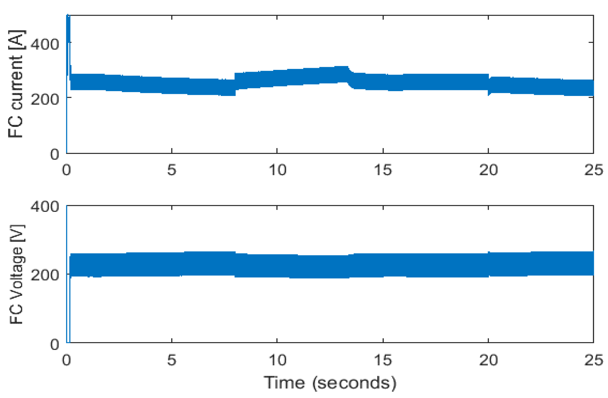
Owing to the slow response time of the fuel cell, it can be observed that the fast power fluctuations can be reduced significantly using the energy storage unit, as shown in
Figure 13. The FC will try to charge the ESU and increase the SOC if the load is not too high.
Figure 14 shows the voltage and current waveforms of the fuel cell.
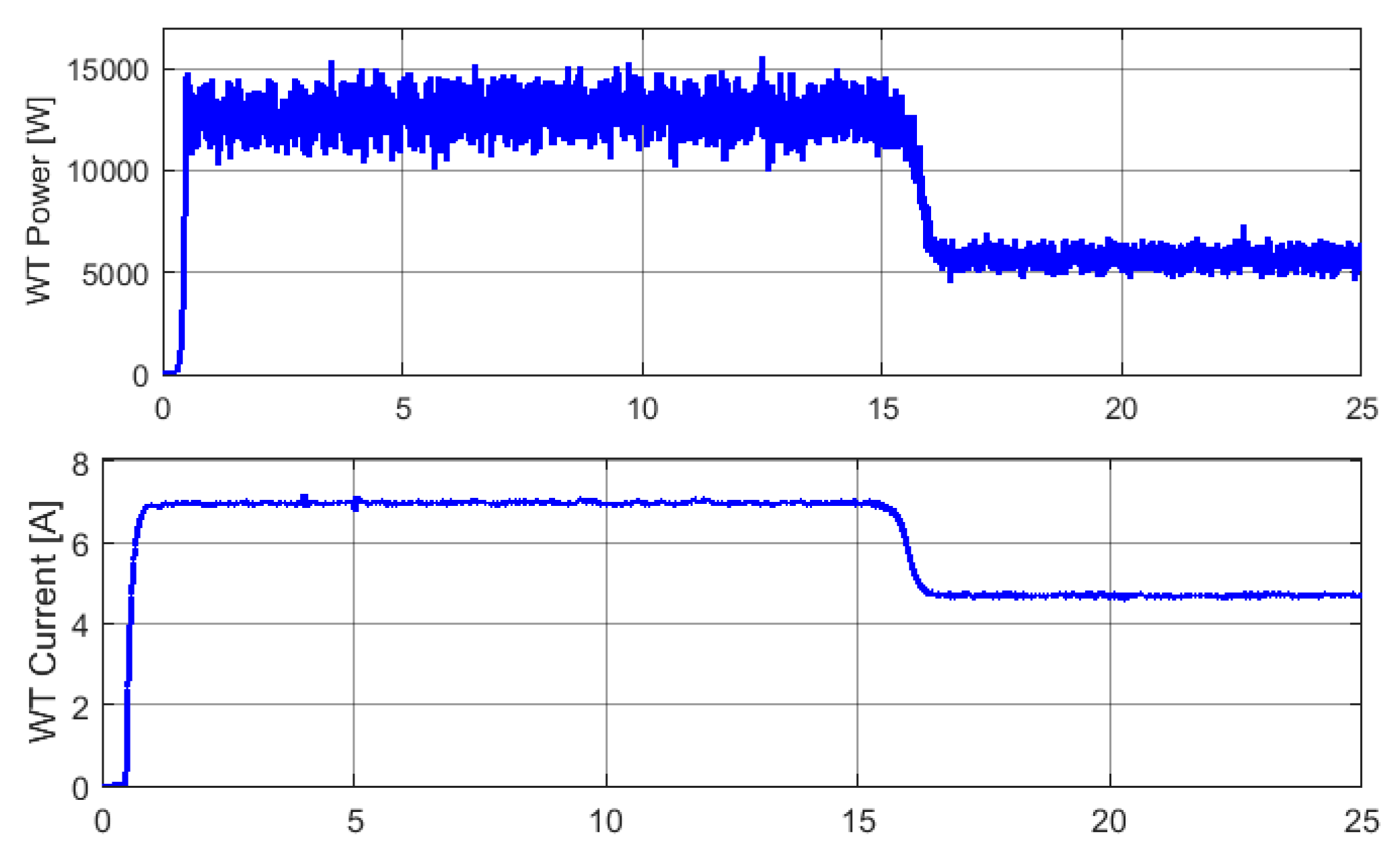
Figure 15 shows the power delivered by the WT generator and the current waveforms. The battery voltage and current waveforms are presented in
Figure 16. It should be noted that a positive current of ESU means that the ESU supplies the load and a negative current means that the ESU is charged. The AC load voltage and current waveforms are shown in
Figure 17. The load current increased at 8 s and decreased at 20 s.
Figure 18,
Figure 19 and
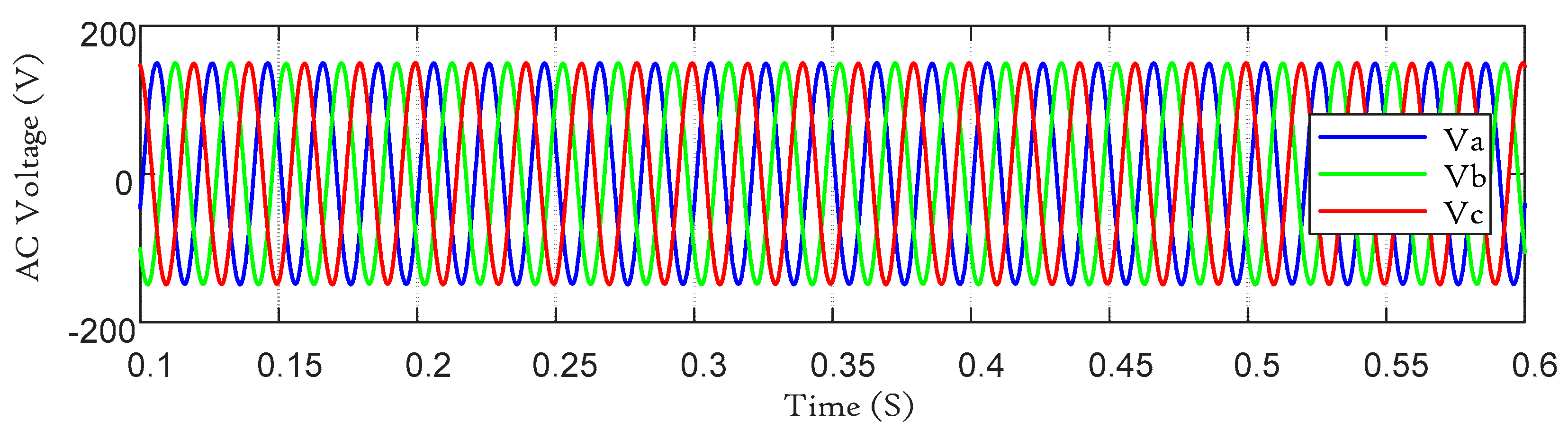
Figure 20 show the simulation results. The output of the three-phase AC voltage and three-phase load current can be seen in
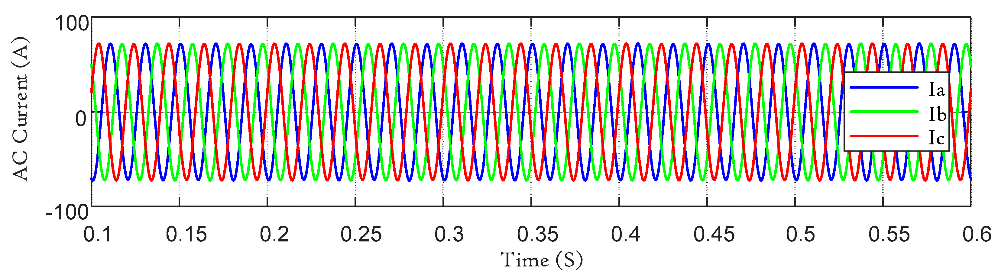
Figure 17. The three-phase currents delivered by the AC inverter are sinusoidal owing to the use of AC filters, as shown in
Figure 18 and
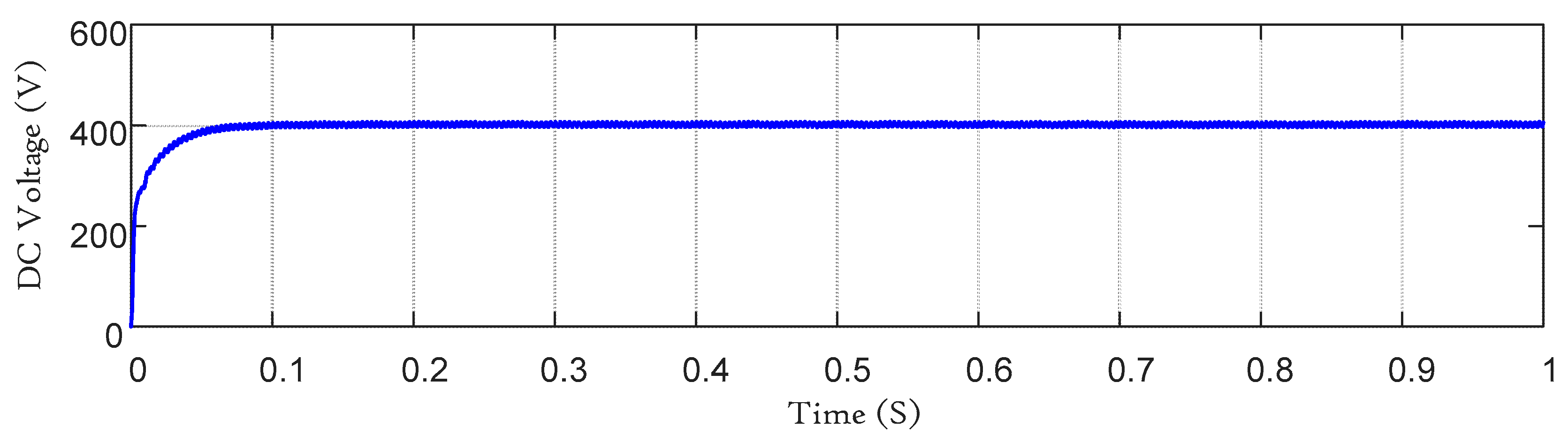
Figure 19. The converter can boost the DC link voltage from a 200 VDC input to a 400 V output voltage. The output current was approximately 7 A. However, the DC-link voltage and current waveforms are shown in
Figure 20 and
Figure 21, respectively.
5. Experimental Verifications
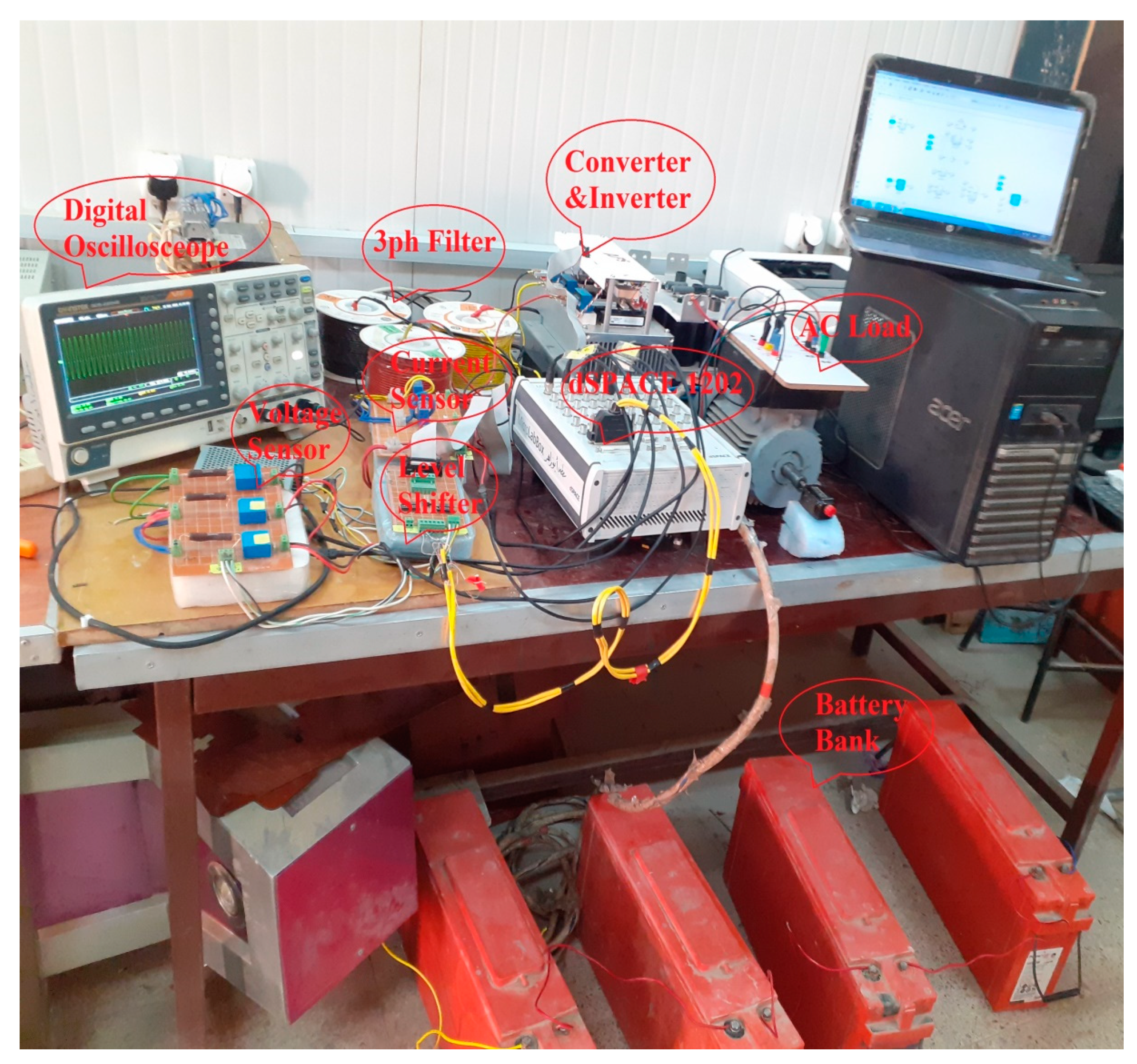
The studied converter has been implemented in the hardware and power management of actual PV panels, fuel cells, and wind turbine hybrid generation systems. The proposed converter control was designed and implemented using a dSPACE controller.
Figure 22 shows the experimental setup circuit consisting of a dSPACE 1202, AC load, 3 phase inverter, lithium-ion battery bank, voltage, and current sensors. The performance of the proposed converter was tested using a 300 W experimental prototype. The effectiveness of the proposed converter topology was demonstrated for renewable energy sources. The technical specifications and circuit parameters of the experimental converter prototype are listed in
Table 3. The switching frequency of the DC-DC converter was selected as 10 kHz.
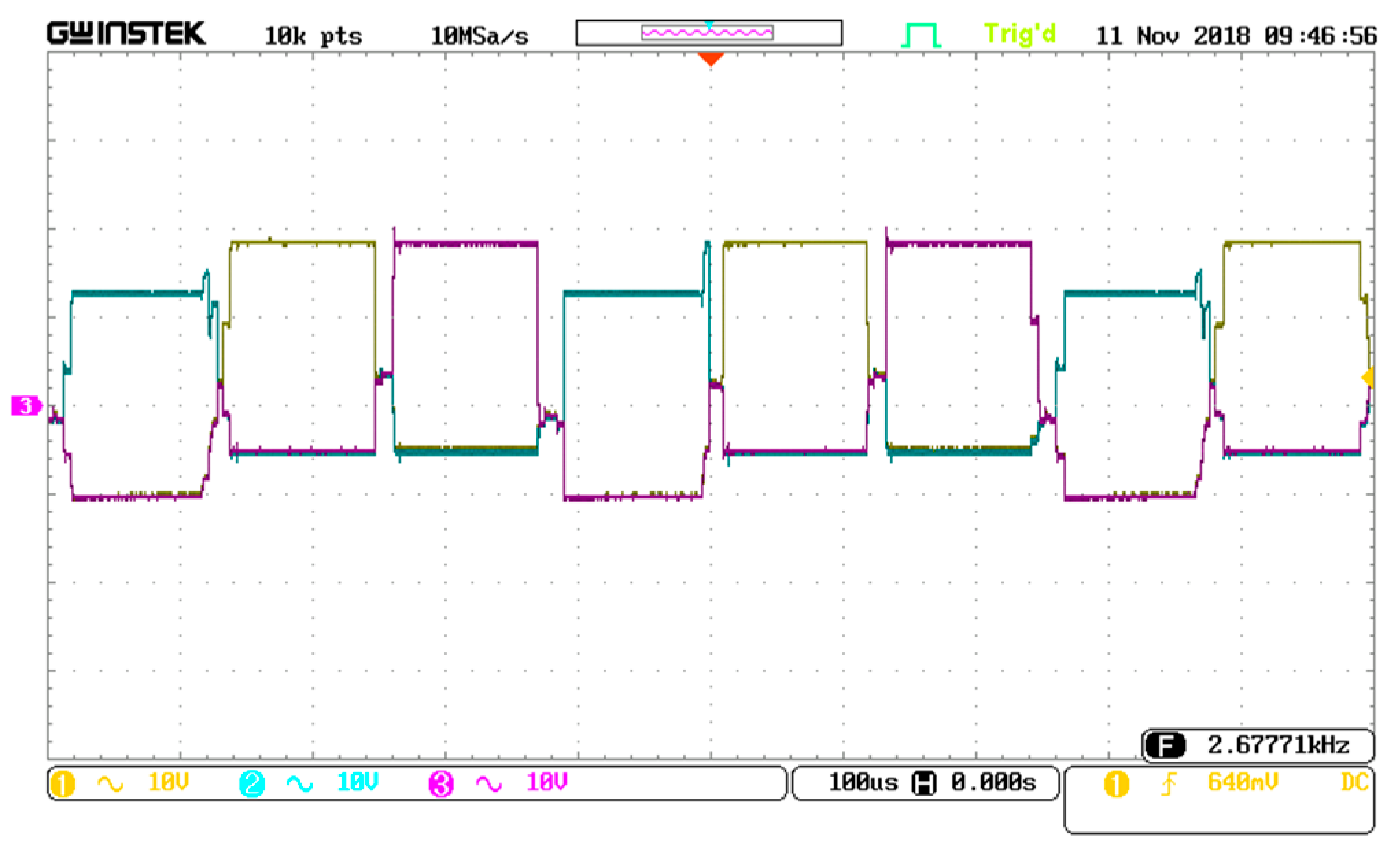
Figure 23 shows the gate-pulse sequence of the active switches of the proposed converter. The three gate pulses are sequenced for an interleaved clocking control scheme.
Figure 24 displays the voltage waveforms across the active switches (
S1,
S2, and
S3). The voltage scale is 10 V per division. In addition, the peak switch voltage is approximately 25 V. Low-voltage stresses through the main active switches can be observed, which equal only one-third of the output voltage. The current waveforms through active switches are shown in
Figure 25 (i
ds1, i
ds2, and i
ds3). In this figure, each voltage division is 1 A. However, the peak current through active switches is approximately 4 A.
Figure 26 shows the waveforms for inductor currents (
iL1,
iL2, and
iL3). The balance between three currents through the boost inductors are shown. In this figure, the peak current in each inductor is approximately 4 A. The three-phase AC output voltages
Va,
Vb, and
Vc are shown in
Figure 27. The input and output DC voltage waveforms are shown in
Figure 28. In this figure, the voltage division is 5 V for the input voltage. Therefore, the input voltage is approximately 20 V. For the output of the voltage signal, the voltage division is 20 V. Consequently, the output voltage is approximately 80 V. In this case, the voltage gain is approximately 4-fold. Thus, the effectiveness of the proposed converter can be proved.
6. Conclusions
In this paper, a multi-port DC-DC power converter was proposed for a synchronized power management of three renewable energy sources (PV panels, fuel cells, and wind turbines) and an energy storage source (batteries or supercapacitors). An energy management system, as well as control of DC-DC power converters, was developed. The simulation results indicate that the proposed energy management method achieves efficient power utilization. The battery energy storage compensates for the slow response of the fuel cells and photovoltaic units. The proposed strategy can share power between DG units, even under a different renewable power generation. An experimental prototype was applied to verify the effectiveness of the proposed multi-port converter topology. The advantages of the studied multiport PWM DC-DC power converter are the simplicity, reliability, and proficiency of MPPT control for several renewable energy sources at the same time. This converter applies multiple functions: it acts as a regulator for charging the battery in a grid-connected operation and as a boost power converter to provide energy from the batteries to the microgrid when there is insufficient power from the solar cell sources, fuel cells, and wind turbines to feed the local loads during an island operation. Furthermore, the integrated converter can be efficiently utilized for the energy management of various renewable energy sources, including energy storage systems. In order to implement a prototype, we have used the real load profile to preserve the load pattern while we scaled down the load magnitude to be 3 KW.


 ,
, 


