
A Real-Time Optimal Car-Following Power Management Strategy for Hybrid Electric Vehicles with ACC Systems


 and
and 
Abstract
1. Introduction
- (1)
- This paper proposes a hierarchical framework that integrates car-following control optimization goals and hybrid energy storage optimization goals to achieve the goal of joint optimization.
- (2)
- The SQP algorithm is adopted to solve the optimization problem in the car-following layer, with the advantage of reducing computational overhead and achieving real-time performance.
- (3)
- The ECMS energy management strategy can not only make full use of the energy of the energy storage device, but also maintain the battery level. It is also helpful for reducing fuel consumption and emissions.
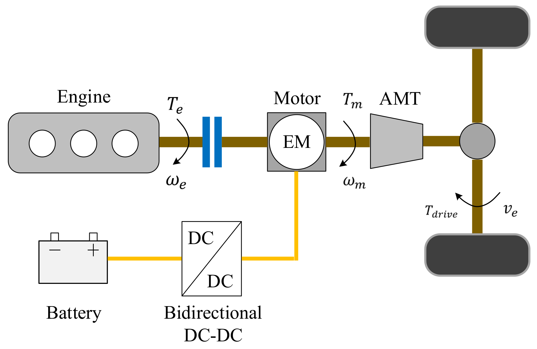
2. Model of the Hybrid Electric Vehicles
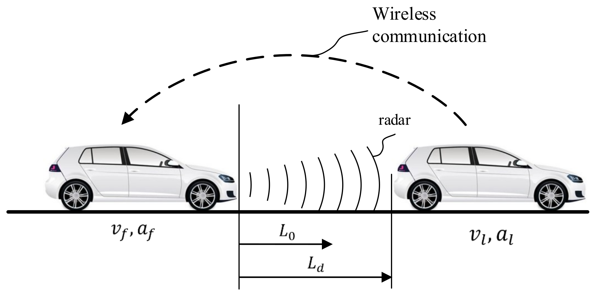
2.1. Longitudinal Dynamics of the Following Vehicle
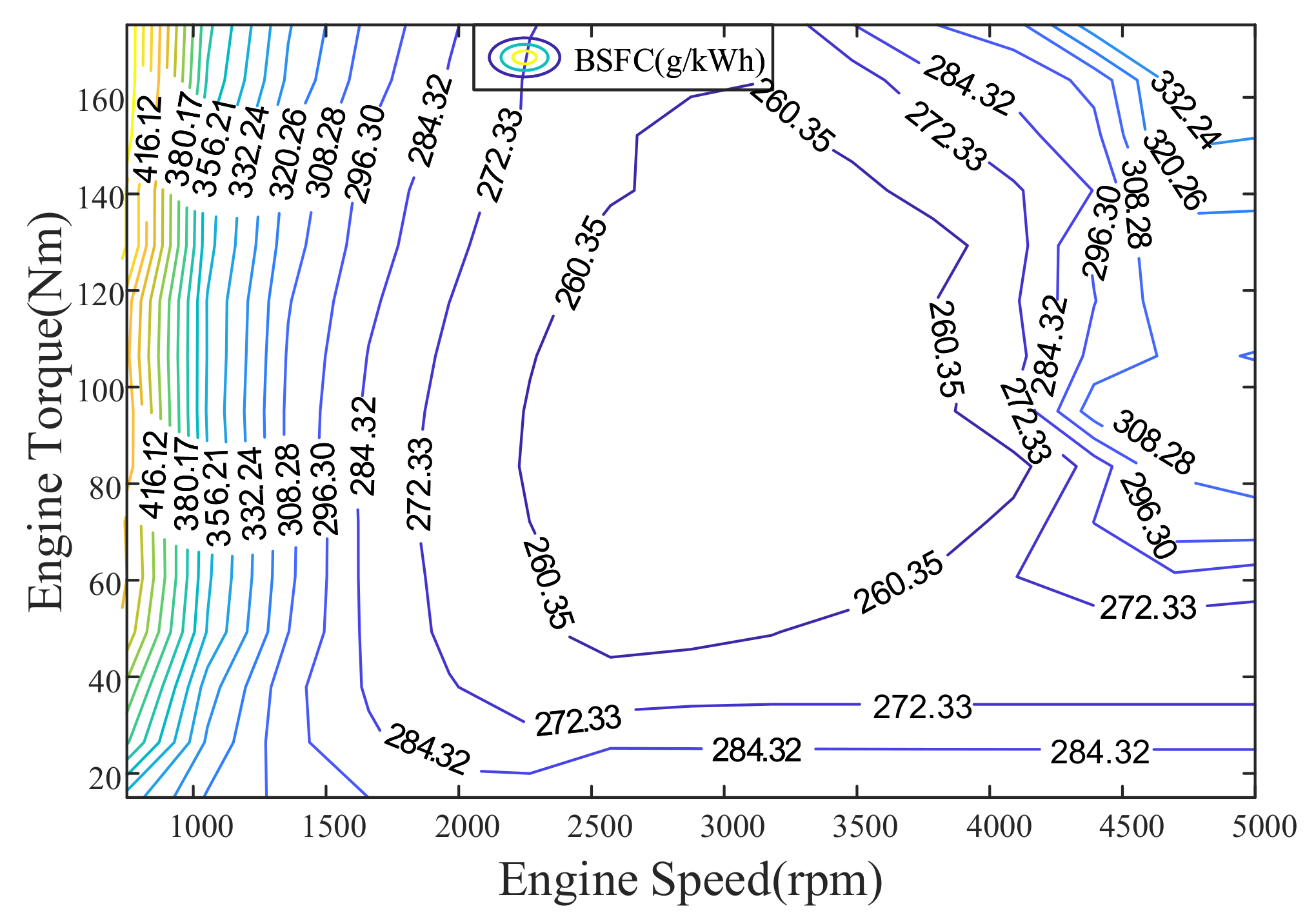
2.2. Engine Fuel Consumption Model
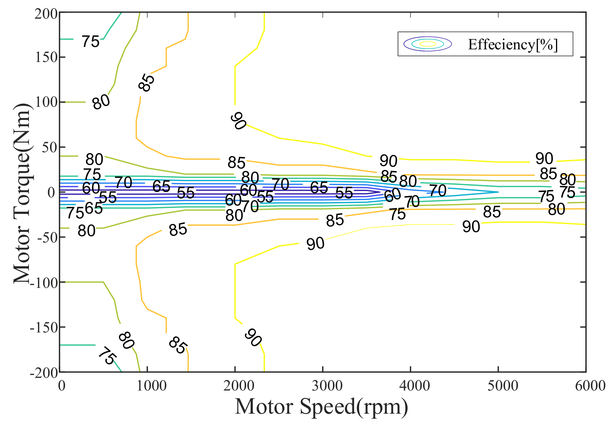
2.3. Electric Motor Model
2.4. Battery Model
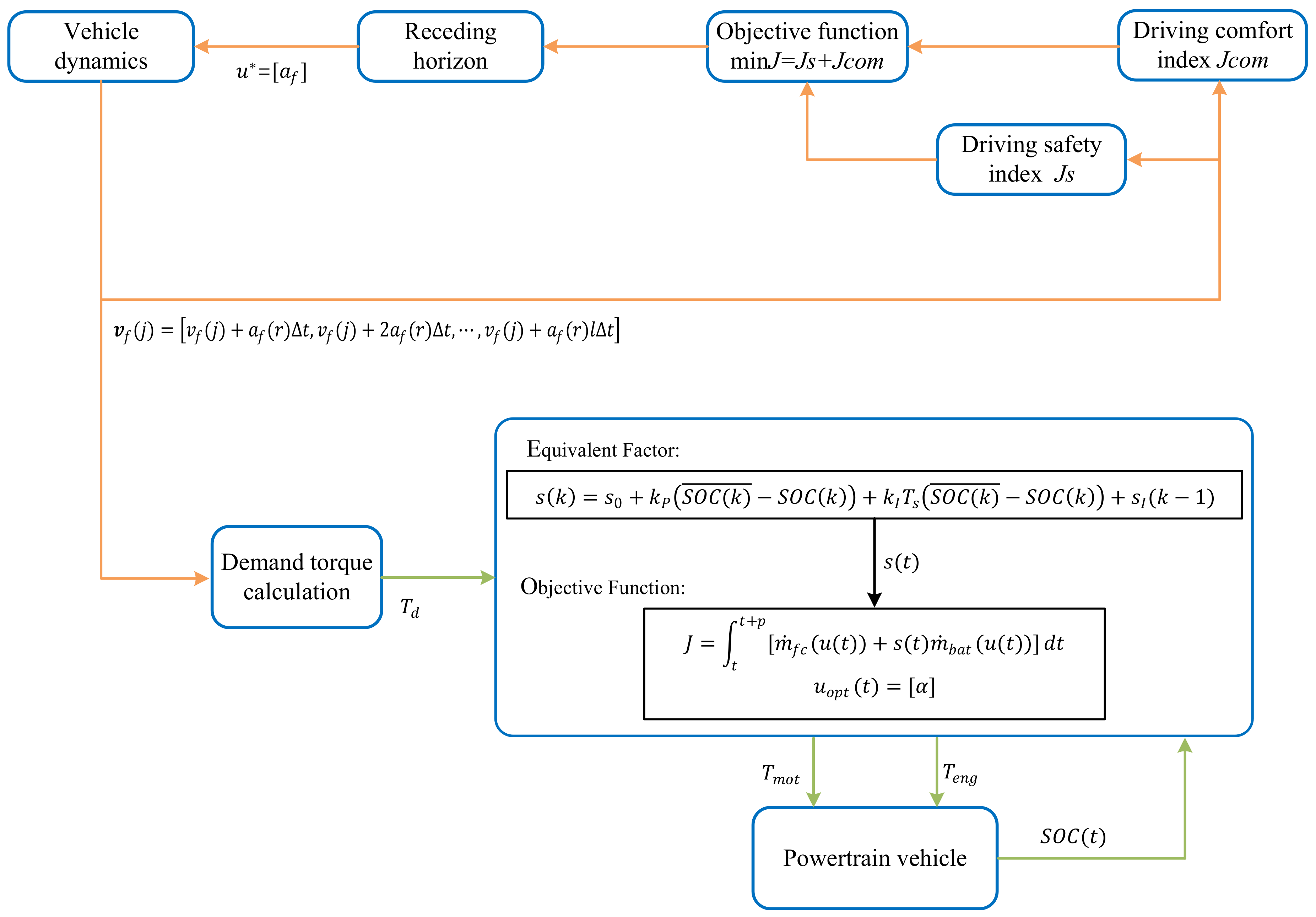
3. Control Strategy
3.1. Car-Following Layer
3.1.1. Driving Safety
3.1.2. Vehicle Comfort
3.1.3. Overall Cost Function
3.1.4. Optimization over the Moving Horizon
3.2. Energy Allocation Layer
4. Simulation Validation
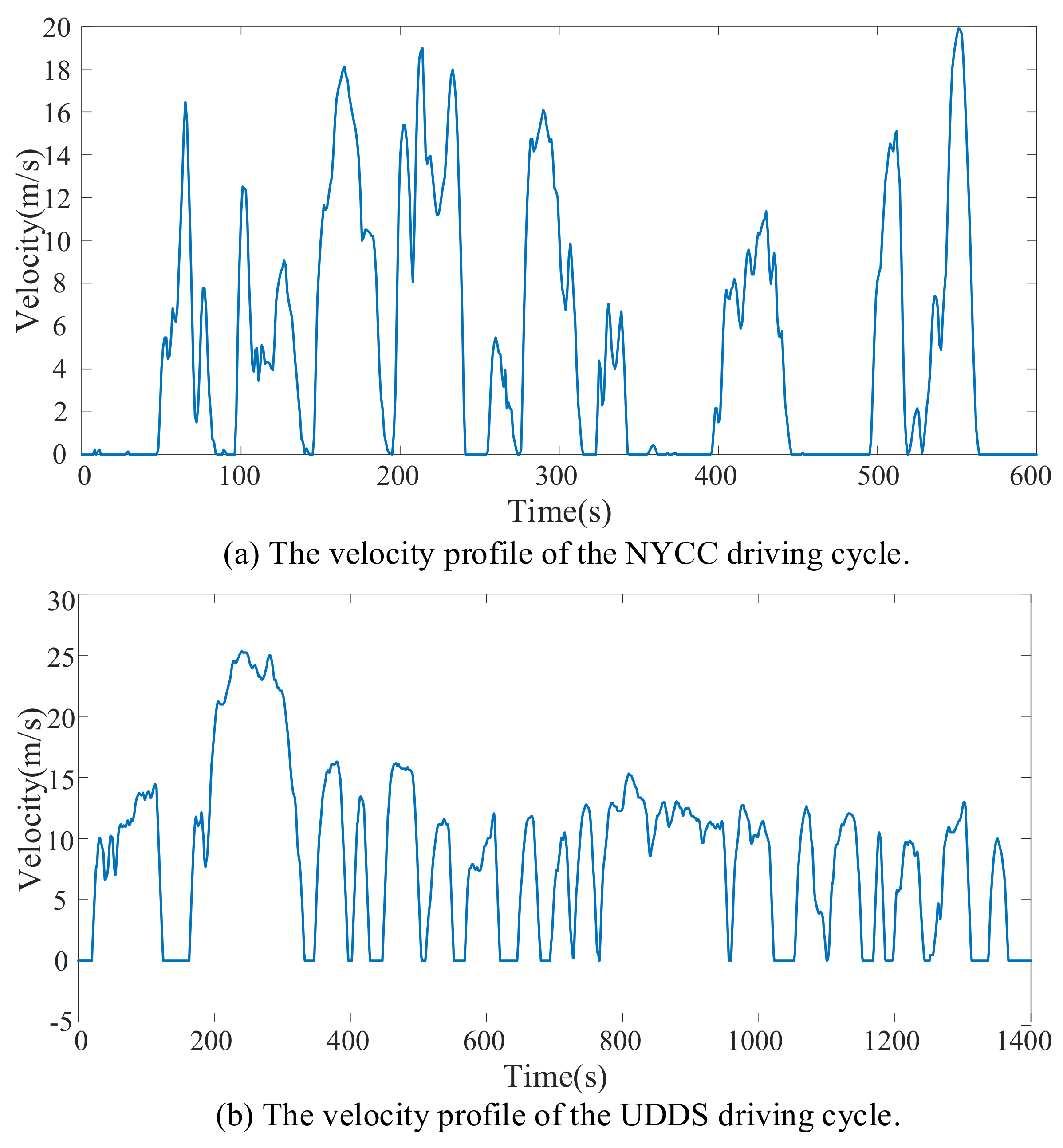
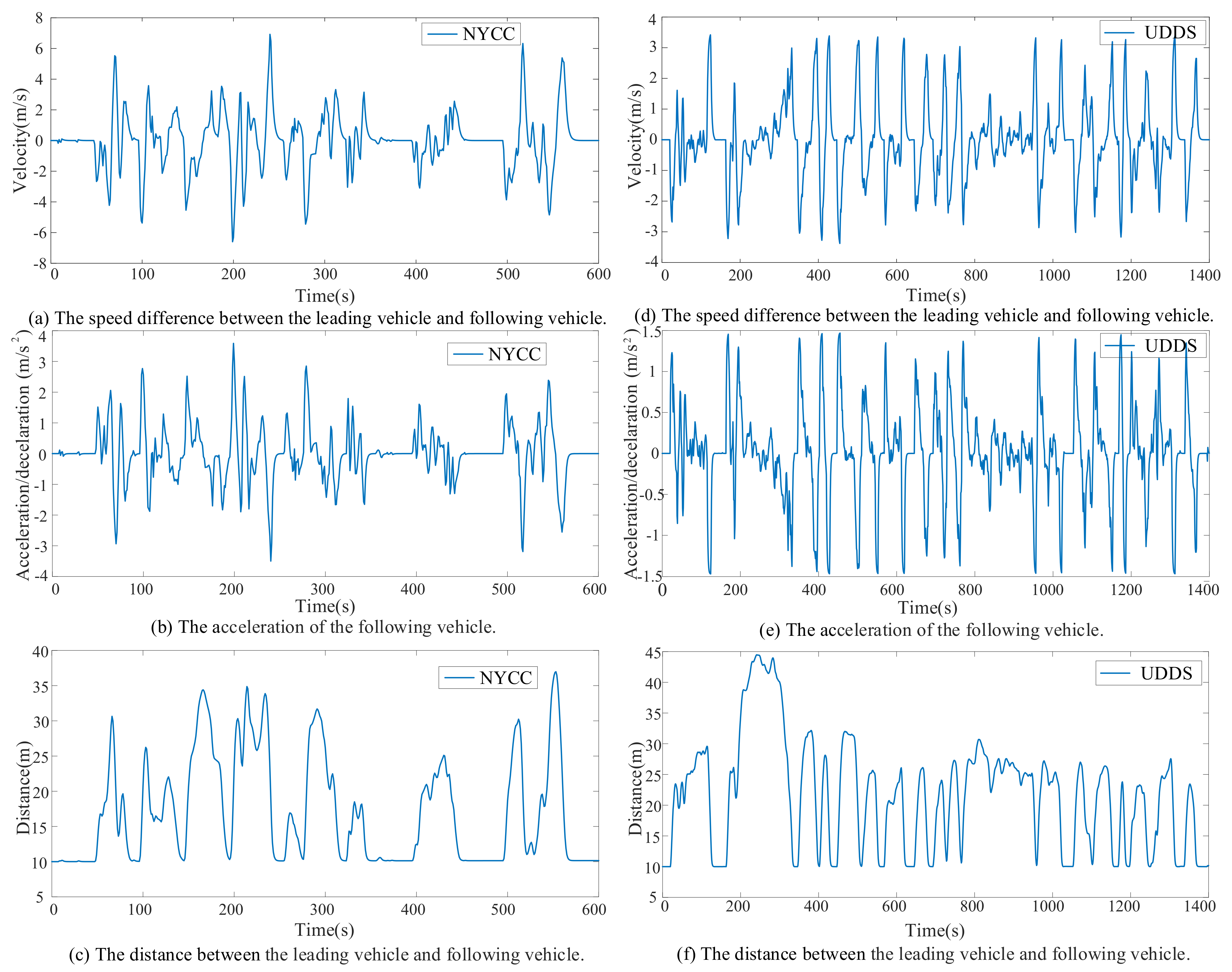
4.1. Car-Following Performance under Different Driving Cycles
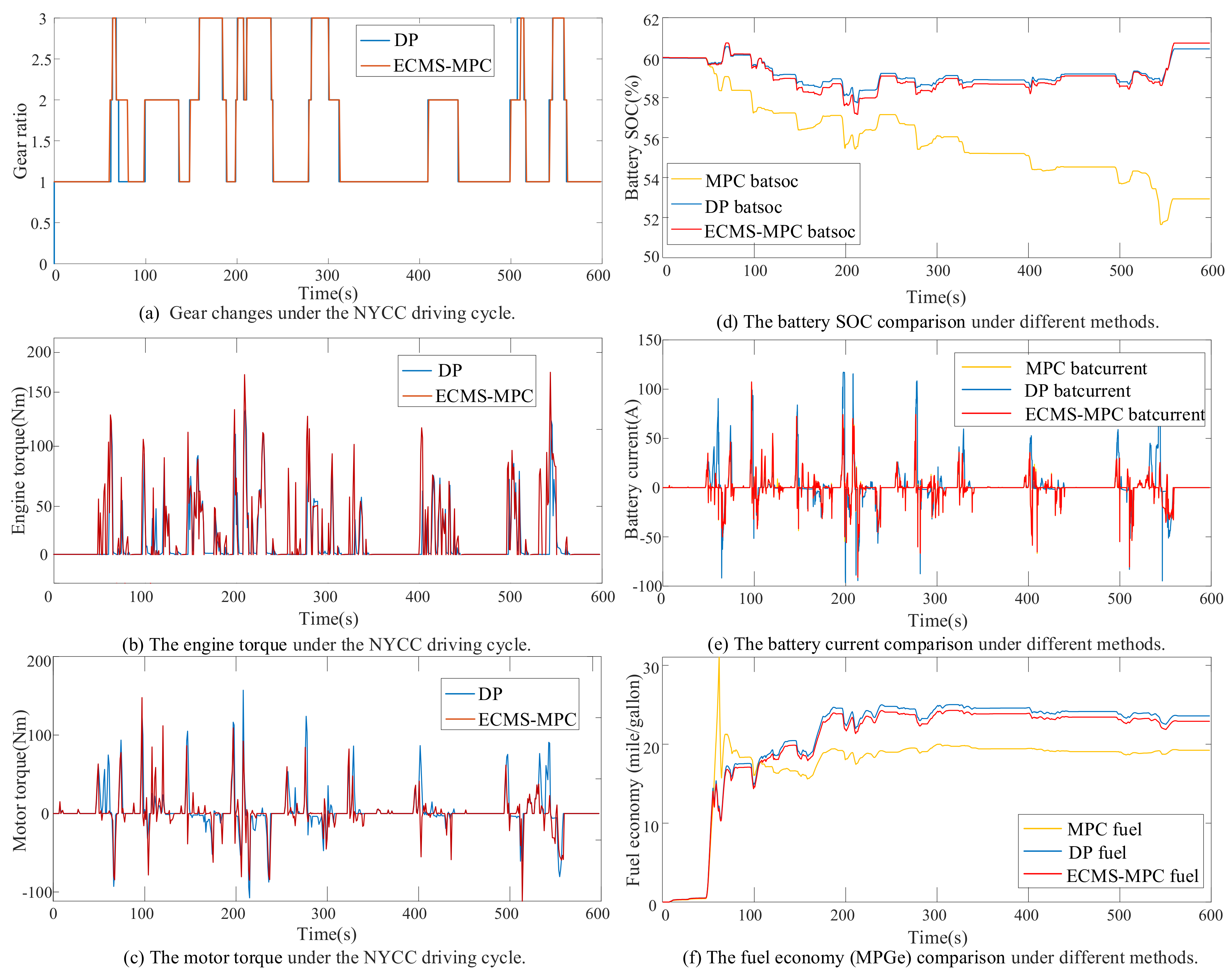
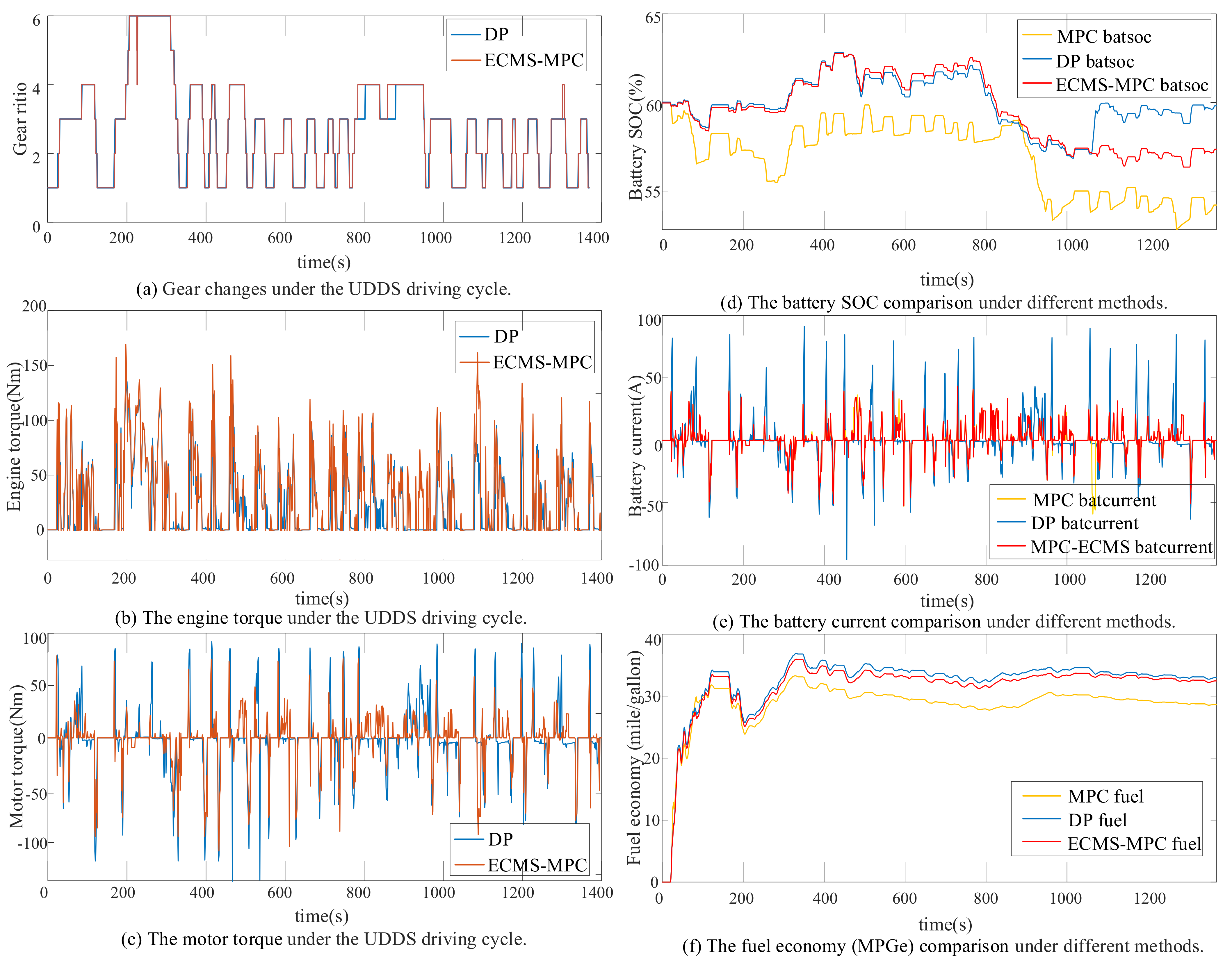
4.2. Energy Allocation Performance under Different Standard Driving Cycles
5. Conclusions
Author Contributions
Funding
Institutional Review Board Statement
Informed Consent Statement
Data Availability Statement
Conflicts of Interest
Abbreviations
| ACC | Adaptive cruise control |
| SOC | State of charge |
| NYCC | New York City Cycle |
| UDDS | Urban Dynamometer Driving Schedule |
| EV | Electric vehicle |
| PID | Proportional integral derivative |
| SMC | Sliding mode control |
| MPC | Model predictive control |
| DP | Dynamic programming |
| PMP | Pontryagin’s minimum principle |
| ECMS | Equivalent fuel consumption minimization Strategy |
| SQP | Sequential quadratic programming |
| BSFC | Brake-specific fuel consumption |
| FC | Fuel cost |
| EC | Electricity cost |
| TEC | Total energy cost |
References
- Shabbir, W.; Evangelou, S.A. Real-time control strategy to maximize hybrid electric vehicle powertrain efficiency. Appl. Energy 2014, 135, 512–522. [Google Scholar] [CrossRef]
- Xu, F.; Shen, T. Look-Ahead Prediction-Based Real-Time Optimal Energy Management for Connected HEVs. IEEE Trans. Veh. Technol. 2020, 69, 2537–2551. [Google Scholar] [CrossRef]
- Wu, D.; Zhu, B.; Tan, D.; Zhang, N.; Gu, J. Multi-objective optimization strategy of adaptive cruise control considering regenerative energy. Proc. Inst. Mech. Eng. Part D J. Automob. Eng. 2019, 233, 3630–3645. [Google Scholar] [CrossRef]
- Zhang, X.; Huang, C.; Liu, M.; Stefanopoulou, A.; Ersal, T. Predictive cruise control with private vehicle-to-vehicle communication for improving fuel consumption and emissions. IEEE Commun. Mag. 2019, 57, 91–97. [Google Scholar] [CrossRef]
- Joševski, M.; Abel, D. Tube-based MPC for the energy management of hybrid electric vehicles with non-parametric driving profile prediction. In Proceedings of the 2016 American Control Conference (ACC), Boston, MA, USA, 6–8 July 2016; IEEE: Piscataway, NJ, USA, 2016; pp. 623–630. [Google Scholar]
- Hussain, M.M.; Memon, Z.A.; Chaudhary, M.A.; Siddique, M. An Innovative PID Controller in Conjunction with DC Electric Motor for Control of Hybrid Electric Vehicle. Int. J. Electr. Electron. Eng. 2020, 7, 20–34. [Google Scholar]
- Hu, X.; Wang, H.; Tang, X. Cyber-physical control for energy-saving vehicle following with connectivity. IEEE Trans. Ind. Electron. 2017, 64, 8578–8587. [Google Scholar] [CrossRef]
- Xie, S.; Hu, X.; Liu, T.; Qi, S.; Lang, K.; Li, H. Predictive vehicle-following power management for plug-in hybrid electric vehicles. Energy 2019, 166, 701–714. [Google Scholar] [CrossRef]
- Hu, X.; Zhang, X.; Tang, X.; Lin, X. Model predictive control of hybrid electric vehicles for fuel economy, emission reductions, and inter-vehicle safety in car-following scenarios. Energy 2020, 196, 117101. [Google Scholar] [CrossRef]
- Xie, S.; Hu, X.; Xin, Z.; Li, L. Time-efficient stochastic model predictive energy management for a plug-in hybrid electric bus with an adaptive reference state-of-charge advisory. IEEE Trans. Veh. Technol. 2018, 67, 5671–5682. [Google Scholar] [CrossRef]
- Li, L.; You, S.; Yang, C.; Yan, B.; Song, J.; Chen, Z. Driving-behavior-aware stochastic model predictive control for plug-in hybrid electric buses. Appl. Energy 2016, 162, 868–879. [Google Scholar] [CrossRef]
- Zhang, F.; Hu, X.; Langari, R.; Cao, D. Energy management strategies of connected HEVs and PHEVs: Recent progress and outlook. Prog. Energy Combust. Sci. 2019, 73, 235–256. [Google Scholar] [CrossRef]
- He, H.; Zhang, J.; Li, G. Model Predictive Control for Energy Management of a Plug-in Hybrid Electric Bus. Energy Procedia 2016, 88, 901–907. [Google Scholar] [CrossRef]
- Banvait, H.; Anwar, S.; Chen, Y. A rule-based energy management strategy for plug-in hybrid electric vehicle (PHEV). In Proceedings of the 2009 American Control Conference, St. Louis, MO, USA, 10–12 June 2009; IEEE: Piscataway, NJ, USA, 2009; pp. 3938–3943. [Google Scholar]
- Wang, D.; Lin, X.; Zhang, Y. Fuzzy logic control for a parallel hybrid hydraulic excavator using genetic algorithm. Autom. Constr. 2011, 20, 581–587. [Google Scholar] [CrossRef]
- Li, G.; Görges, D. Ecological adaptive cruise control and energy management strategy for hybrid electric vehicles based on heuristic dynamic programming. IEEE Trans. Intell. Transp. Syst. 2018, 20, 3526–3535. [Google Scholar] [CrossRef]
- Zeng, X.; Wang, J. A two-level stochastic approach to optimize the energy management strategy for fixed-route hybrid electric vehicles. Mechatronics 2015, 38, 93–102. [Google Scholar] [CrossRef]
- Martinez, C.M.; Hu, X.; Cao, D.; Velenis, E.; Gao, B.; Wellers, M. Energy Management in Plug-in Hybrid Electric Vehicles: Recent Progress and a Connected Vehicles Perspective. IEEE Trans. Veh. Technol. 2017, 66, 4534–4549. [Google Scholar] [CrossRef]
- Ali, A.M.; Söffker, D. Towards optimal power management of hybrid electric vehicles in real-time: A review on methods, challenges, and state-of-the-art solutions. Energies 2018, 11, 476. [Google Scholar]
- Barsali, S.; Miulli, C.; Possenti, A. A control strategy to minimize fuel consumption of series hybrid electric vehicles. IEEE Trans. Energy Convers. 2004, 19, 187–195. [Google Scholar] [CrossRef]
- Zhang, F.; Xi, J.Q.; Langari, R. An adaptive equivalent consumption minimization strategy for parallel hybrid electric vehicle based on fuzzy pi. In Proceedings of the 2016 IEEE Intelligent Vehicles Symposium (IV), Gothenburg, Sweden, 19–22 June 2016; IEEE: Piscataway, NJ, USA, 2016; pp. 460–465. [Google Scholar]
- Xie, S.; Hu, X.; Qi, S.; Lang, K. An artificial neural network-enhanced energy management strategy for plug-in hybrid electric vehicles. Energy 2018, 163, 837–848. [Google Scholar] [CrossRef]
- Xie, S.; Hu, X.; Qi, S.; Tang, X.; Lang, K.; Xin, Z.; Brighton, J. Model predictive energy management for plug-in hybrid electric vehicles considering optimal battery depth of discharge. Energy 2019, 173, 667–678. [Google Scholar] [CrossRef]
- Zhang, F.; Xi, J.; Langari, R. Real-time energy management strategy based on velocity forecasts using V2V and V2I communications. IEEE Trans. Intell. Transp. Syst. 2016, 18, 416–430. [Google Scholar] [CrossRef]
- Hussain, M.M.; Chaudary, M.A.; Razaq, A. Design and implementation of hybrid vehicle using control of DC electric motor. In Proceedings of the 2019 54th International Universities Power Engineering Conference (UPEC), Bucharest, Romania, 3–6 September 2019; IEEE: Piscataway, NJ, USA, 2019; pp. 1–6. [Google Scholar]
- Hu, X.; Li, S.E.; Yang, Y. Advanced machine learning approach for lithium-ion battery state estimation in electric vehicles. IEEE Trans. Transp. Electrif. 2015, 2, 140–149. [Google Scholar] [CrossRef]
- Li, L.; Wang, X.; Song, J. Fuel consumption optimization for smart hybrid electric vehicle during a car-following process. Mech. Syst. Signal Process. 2017, 87, 17–29. [Google Scholar] [CrossRef]
- Luo, Y.; Chen, T.; Zhang, S.; Li, K. Intelligent hybrid electric vehicle ACC with coordinated control of tracking ability, fuel economy, and ride comfort. IEEE Trans. Intell. Transp. Syst. 2015, 16, 2303–2308. [Google Scholar] [CrossRef]
- Onori, S.; Serrao, L.; Rizzoni, G. Equivalent Consumption Minimization Strategy. In Hybrid Electric Vehicles. SpringerBriefs in Electrical and Computer Engineering; Springer: London, UK, 2016. [Google Scholar]


| Components | Specifications |
|---|---|
| Engine | FC-SI41 (Simulink) |
| Maximum torque : 170 Nm | |
| Maximum speed : 5000 rpm | |
| Electric machine | MC-PM30 (Simulink) |
| Maximum power: 30 kW | |
| Maximum torque : 200 Nm | |
| Minimum torque : −200 Nm | |
| Maximum speed : 6000 rpm | |
| AMT | Gear ratio: [1, 4.212, 2.637, 1.8, 1.386, 0.772] |
| Battery pack | ESS-NIMH6 (Simulink) |
| Capacity, : 5.3 Ah = 19,080 C | |
| Coulombic efficiency, : 0.95 | |
| Nominal voltage: 273 V |
| Symbol | Characteristic (Unit) | Value |
|---|---|---|
| m | Vehicle mass (kg) | 1623 |
| g | Gravitational constant | 9.81 |
| Aerodynamic drag coefficient (-) | 0.25 | |
| Rolling resistance coefficient (-) | 0.9 | |
| A | Frontal area (m) | 2.46 |
| Air density (kg/m) | 1.29 | |
| Wheel radius (m) | 0.34 | |
| Final drive ratio | 4.55 | |
| h | Constant headway time (s) | 2.5 |
| Weight coefficient | 3 | |
| Weight coefficients | 0.1 | |
| Initial value of equivalent factor | 4 | |
| Sampling time (s) | 1 |
| Method | FC (CNY) | EC (CNY) | TEC (CNY) | Final SOC | Time (s) |
|---|---|---|---|---|---|
| MPC | 34.12 | 27.34 | 61.47 | 0.53 | 0.006 |
| ECMS-MPC (5 s) | 18.79 | 29.03 | 47.82 | 0.606 | 0.136 |
| ECMS-MPC (3 s) | 14.18 | 28.64 | 42.83 | 0.605 | 0.122 |
| DP | 10.10 | 29.13 | 39.24 | 0.603 | 17.79 |
| Method | FC (CNY) | EC (CNY) | TEC (CNY) | Final SOC | Time (s) |
|---|---|---|---|---|---|
| MPC | 32.43 | 25.62 | 57.47 | 0.538 | 0.007 |
| ECMS-MPC (5 s) | 17.46 | 28.34 | 45.54 | 0.574 | 0.135 |
| ECMS-MPC (3 s) | 13.12 | 28.96 | 42.13 | 0.579 | 0.119 |
| DP | 9.28 | 29.34 | 38.72 | 0.596 | 28.36 |
Publisher’s Note: MDPI stays neutral with regard to jurisdictional claims in published maps and institutional affiliations. |
© 2021 by the authors. Licensee MDPI, Basel, Switzerland. This article is an open access article distributed under the terms and conditions of the Creative Commons Attribution (CC BY) license (https://creativecommons.org/licenses/by/4.0/).
Share and Cite
Sun, X.; Liu, W.; Wen, M.; Wu, Y.; Li, H.; Huang, J.; Hu, C.; Huang, Z. A Real-Time Optimal Car-Following Power Management Strategy for Hybrid Electric Vehicles with ACC Systems. Energies 2021, 14, 3438. https://doi.org/10.3390/en14123438
Sun X, Liu W, Wen M, Wu Y, Li H, Huang J, Hu C, Huang Z. A Real-Time Optimal Car-Following Power Management Strategy for Hybrid Electric Vehicles with ACC Systems. Energies. 2021; 14(12):3438. https://doi.org/10.3390/en14123438
Chicago/Turabian StyleSun, Xiaobo, Weirong Liu, Mengfei Wen, Yue Wu, Heng Li, Jiahao Huang, Chao Hu, and Zhiwu Huang. 2021. "A Real-Time Optimal Car-Following Power Management Strategy for Hybrid Electric Vehicles with ACC Systems" Energies 14, no. 12: 3438. https://doi.org/10.3390/en14123438
APA StyleSun, X., Liu, W., Wen, M., Wu, Y., Li, H., Huang, J., Hu, C., & Huang, Z. (2021). A Real-Time Optimal Car-Following Power Management Strategy for Hybrid Electric Vehicles with ACC Systems. Energies, 14(12), 3438. https://doi.org/10.3390/en14123438