Article

Multifaceted Comparison Efficiency and Emission Characteristics of Multi-Fuel Power Generator Fueled by Different Fuels and Biofuels

1
Department of Food Technology and Nutrition, Wrocław University of Economics, 118/120 Komandorska Street, 53-345 Wroclaw, Poland
2
Department of Agroengineering and Quality Analysis, Wrocław University of Economics, 118/120 Komandorska Street, 53-345 Wroclaw, Poland
3
Department of Civil Engineering and Transport, Poznan University of Technology, Plac Marii Skłodowskiej-Curie 5, 60-965 Poznan, Poland
4
Department in Wroclaw, Institute of Technology and Life Sciences, 7 Motykowny Street, 51-209 Wroclaw, Poland
5
Department of Power Engineering and Transportation, Faculty of Production Engineering, University of Life Sciences in Lublin, 28 Głęboka Street, 20-612 Lublin, Poland
*
Author to whom correspondence should be addressed.
Energies 2021, 14(12), 3388; https://doi.org/10.3390/en14123388
Submission received: 28 April 2021 / Revised: 3 June 2021 / Accepted: 4 June 2021 / Published: 8 June 2021

Abstract

:
The negative effect of liquid and gaseous fuel combustion is toxic gases (i.e., carbon and nitrogen oxides NOx) and particulate matter (PM) formation. The content of harmful and toxic components of exhaust gases is strongly dependent on the quality and type of burnt fuel. Experimental research is required to verify the use of current technical and technological solutions for the production of electricity on farms, using various types of conventional fuels and biofuels. The aim of the current research was to comprehensively verify the use of commonly available fuels and biofuels without adapting the internal combustion engine. Gaseous fuels—propane-butane mixture (LPG), compressed natural gas (CNG) and biogas (BG)—were added to liquid fuels—methyl esters of higher fatty acids (RME) and diesel fuel (DF)—in six different power configurations to evaluate the effect on the emission of toxic gases: carbon monoxide (CO), nitric oxide (NO), nitric dioxide (NO2) and particulate matter (PM), and the efficiency of fuel conversion. The use of RME in various configurations with gaseous fuels increased the emission of oxides and reduced the emission of PM. Increasing the share of LPG and CNG significantly increased the level of NO emissions. The use of gaseous fuels reduced the efficiency of the generator, particularly in the case of co-firing with DF. For medium and high loads, the lowest decrease in efficiency was recorded for the RME configuration with BG. Taking into account the compromise between individual emissions and the configuration of RME with BG, the most advantageous approach is to use it in power generators.

1. Introduction

Due to the growing energy demands of society and decreasing resources of fossil fuels, interest in renewable energy sources (RES) is rising [1,2]. Utilizing RES is also an effective method of managing the excess of biomass produced by the agriculture and food industry [3,4].
Among the effective means of biomass utilization are alcoholic fermentation, the product of which is bioethanol [5,6,7], or methane fermentation, the product of which is biogas [8,9,10]. These fuels are often used for spark-ignition internal combustion engines (SI). However, compression-ignition (CI) engines are more thermally efficient than spark-ignition engines and, therefore, in recent years, increased efforts have been observed to adapt these engines to biogas combustion [11,12,13]. The combustion of biogas and other gaseous fuels in a CI engine requires the initiation of the combustion process by injecting a small dose of fuel with high self-ignition capabilities [13,14]. The pilot dose of liquid fuel is usually diesel fuel [15]. To change the performance indicators of CI engines fueled by gaseous fuels, experimental studies on simultaneous combustion of gaseous and liquid fuels have been carried out [16,17]. The fuels applied in such engines may also include methyl esters of higher fatty acids (RME) [12], the mixture of propane and butane (LPG) [18,19,20], and natural gas in liquid form (LNG) [21,22,23] or compressed as CNG [17,24,25,26], in addition to biogas [12,27,28,29]. A negative consequence of the combustion of both liquid and gaseous fuels in internal combustion engines is the production of exhaust gases that result from physical and chemical in-cylinder processes [30,31,32]. Due to their chemical composition, these gases have an adverse effect on the environment and human health [33,34]. Particularly harmful for the environment is the emission of acid oxides, i.e., SO2 and SO3, and NOx, which causes acid rain [35,36,37]. In the case of CI engines fueled with liquid fossil fuels, the problem is the increased NOx emissions compared to that of SI engines [38]. This is due to the mixture formation system design, which results in the non-uniform composition of the combustion mixture, leading to different post-flame gas temperatures [39]. An additional problem is increased emission of particulate matter (PM) caused by soot, which in turn results from an incomplete combustion process [4,40]. In addition, the exhaust gases also include carbon oxides (CO, CO2) and hydrocarbons (HC) [4,30,41]. Published research results indicate a change in the content of individual toxic and harmful exhaust components due to biofuel combustion in CI engines relative to diesel [12,40,42,43]. This creates possibilities of significant reduction in exhaust gas emission by application of plant origin fuels. The results of experimental works indicate the potential of using biodiesel for reductions in CO emissions of 11–59% [39,41,44], HC emissions of 25–45% [12,40,41,43], and PM emissions of 10–73% [4,43,45]. Discrepancies exist in NOx and CO2 emissions depending on the source. Dorado et al. [45] showed a 32% reduction in NOx emissions, whereas other studies [46,47] resulted in a 3% reduction in CO2 emissions. In contrast, a study by Ulusoy et al. [48] obtained increases in NOx and CO2 emissions of 5 and 3%, respectively. In addition to the use of biodiesel in dual fuel engines, design changes have been made to reduce the interrelated NOx and PM emissions [49]. Experimental studies have also been conducted to adjust the fuel supply system to changed physicochemical parameters of fuels. In addition, work is underway to replace part of the DF dose with another liquid fuel, for example, alcohol [50] or gaseous fuel (LPG, LNG, NG, BG) [23,51,52,53,54], which also translates into a simultaneous reduction in NOx and PM. Currently, a trend can be found in research on dual-fuel engines, in which fuels containing a reduced proportion of carbon to hydrogen are introduced, in addition to changes in the fuel supply system or engine control parameters [26]. Research conducted by Beatrice et al. [55] consisting of partial replacement of DF by ethanol, in addition to the use of changes in the injectors, confirms the effectiveness of reducing both NOx, CO2 and PM.
Combustion of biogas in a dual-fuel engine is a novel approach to promote the efficient use of biogas [56,57]. It reduces NO emissions by 35–39%, NOx by 37%, CO2 by 42%, and PM by 70%. However, the disadvantage is the increase in CO and HC emissions, by 16–17% and 21–30%, respectively [29,58,59,60]. The ignition mechanism used in such engines generates high activation energy compared to conventional spark ignition. This provides an opportunity for efficient combustion of low-quality biogas.
Experimental research is needed to verify the use of current technical and technological solutions for the production of electricity on farms, using various types of conventional fuels and biofuels. Many research works have undertaken detailed analyses of the influence of various types of fuel on the energy and emission parameters of the internal combustion engine. The results of these tests concern only selected fuel configurations. The aim of the current research was to comprehensively verify the use of commonly available fuels and biofuels without adapting the internal combustion engine. The desired outcome was to determine how an engine that is not adapted for biofuels would run on them in relation to the control results. The liquid fuels were diesel fuel as a control sample and methyl esters of higher fatty acids. Liquid fuels were used in combination with gaseous fuels—LPG, CNG and BG—which resulted in six different power configurations for the electric energy generator engine. Important criteria for assessing the impact of the type of fuel were the environmental aspect, i.e., the level of exhaust gas emissions such as CO, NO, NO2 and PM, and the energy aspect, i.e., the efficiency of fuel conversion in electricity generating units.

2. Materials and Methods

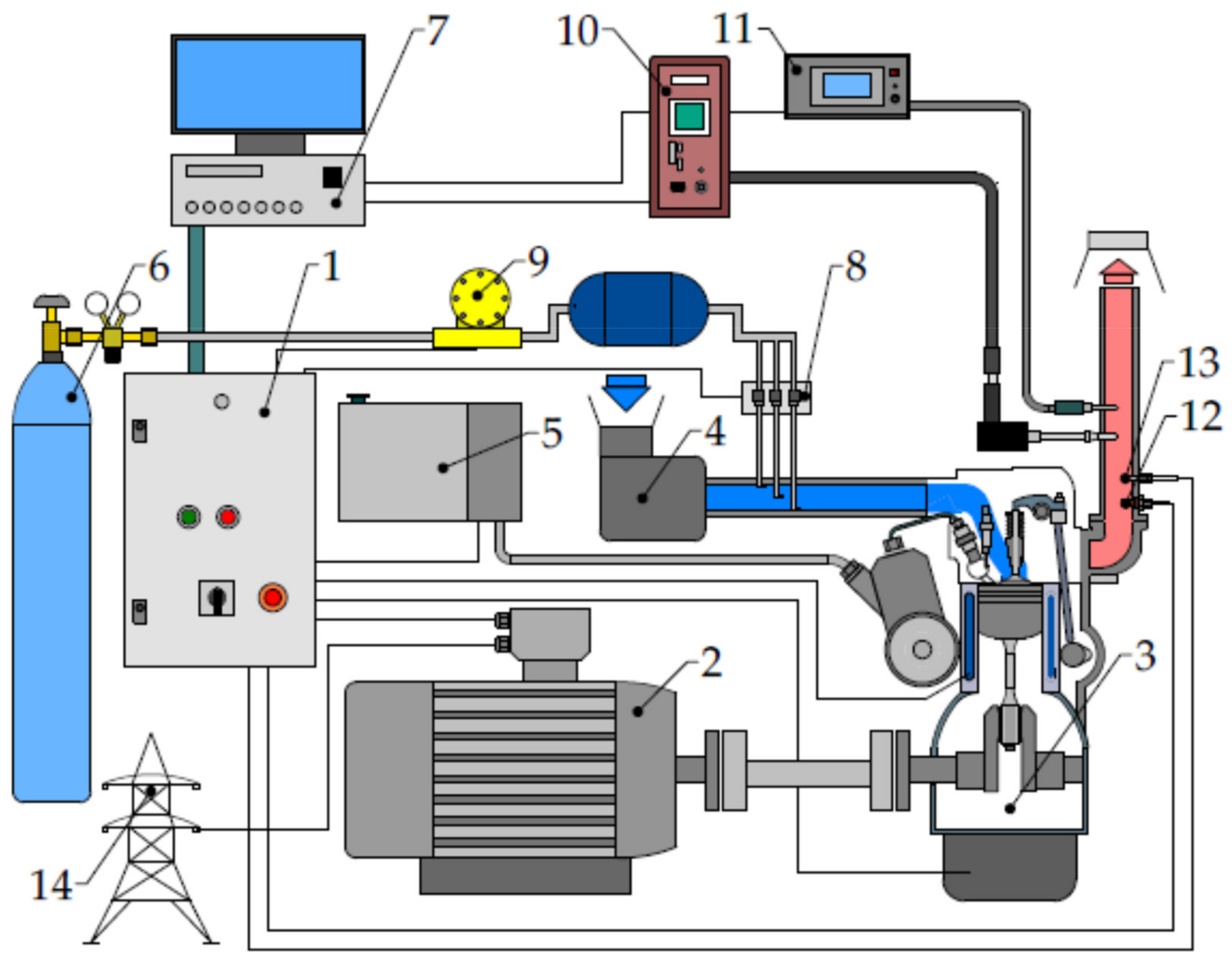
2.1. Test Stand and Fuels

The experiments were conducted on an ATMX 2000 dynamometer test stand, which included a Yanmar 2TNV70-ASA two-cylinder CI engine (Table 1) equipped with a divided combustion chamber and a cooling water system. The rated power of the engine was 9.76 KW. The injection system was built with an Inline fuel injection pump and hydraulically controlled injectors delivering fuel to the pre-combustion chamber. The engine was permanently connected via a shaft to an asynchronous electric motor controlled by automatic control and measurement system. The air-cooled asynchronous motor OMT1-160 M2 (Table 2) was a three-phase low voltage induction motor with a squirrel cage rotor. The bench was equipped with a 15 kW MFC 710 inverter. The electricity generated during the operation of the internal combustion engine was routed directly to the power grid. PARM software, consisting of the ParmSuite package, was used to manage, control, and perform tests on the ATMX2000 test stand. The concentration of selected gaseous components of the exhaust gases was measured using the electrochemical method with the VARIOplus Industrial exhaust gas analyzer. The particulate matter concentration was determined by the photometric method (laser light scattering photometer) using the MPM-4 measuring device. A scheme of the experimental stand is shown in Figure 1.
The chemical composition of the liquid biofuel examined was determined according to the ISO 12966:2014 standard prescribed for methyl esters, and the results are presented in Table 3. The liquid fuels’ density was tested using an areometer according to the PN-EN ISO 3675 standard (Table 4). Simultaneously, the kinematic viscosity was measured using a capillary according to the PN-ISO 3104 standard (Table 4). The heating value of liquid fuels was determined using an IKA C 200 calorimeter (Table 4). The biogas used in this study was obtained from the plant, then compressed into pressure vessels at a pressure of 100 bar. A sample was taken from the pressure vessel to determine the composition of the biogas. Biogas composition analyses were performed using a GA2000 (Table 5); density and calorific value were calculated from the gas composition and tabular data for methane and carbon dioxide.

2.2. Experimental Conditions and Procedures

In the first stage of research, the influence of liquid fuel types on CI engines’ performance and emissions in the entire operating range was determined. For this purpose, the full load characteristics of the engine sequentially fed with diesel fuel and rapeseed oil methyl esters were verified. The engine was operated in the speed range of 1400–3400 rpm, determined by changing the electric motor’s load. The engine speed n (rpm), torque Mo (Nm), and hourly fuel consumption Ge (kg·h−1) were recorded during the test stand operation. The power of the internal combustion engine Ne (KW) and specific fuel consumption ge (g·kWh−1) were calculated based on the measured values. The atmospheric conditions in the laboratory during the measurements were approximately constant and were as follows: humidity (46% ± 10%); pressure (995 ± 2 hPa); temperature (20 ± 2 °C). All phases of testing were conducted on a preheated engine (oil temperature >70 °C). After stabilizing engine operating parameters at specific operating points, concentrations of selected components of exhaust gases were measured. CO, NO, NO2, and PM were selected to analyze the internal combustion engine’s emission factors. The next stage of the research was evaluating emission and energy indices of the engine’s operation when simultaneously fueled with two fuels of different physicochemical parameters. The tests were carried out for six types of mixtures containing two liquid and three gaseous fuels. The tests were carried out in six configurations, as presented in the Table 6.
The ambient conditions and the initial thermal condition of the engine remained unchanged. In this part of the study, the engine was operated at a constant engine speed of 1500 ± 30 rpm, controlled through the fuel dosing system. The tests’ scope included varying the load for six brake torque values in the range of 0–20 Nm and varying the share of each fuel supplied to the engine. The liquid fuel injection pump controller automatically adjusted the dose and decreased it as the gaseous fuel proportion rose. Figure 2 shows the points above which an increase in the proportion of gaseous fuel caused unstable engine operation leading to the aggregate stop. The gaseous fuel injection system consisted of three electromagnetic injectors supplying gas to the intake manifold at a pressure of 2 bar. To obtain a better homogeneity of the gas–air mixture, the gas was supplied in 3 different positions of the intake manifold. As the share of gaseous fuel increased, the amount of fuel (RME, DF) delivered directly to the cylinder was reduced. Fuel consumption was measured separately for liquid fuel using a fuel consumption measuring system and gaseous fuel using a mass flow meter. Subsequently, an exhaust gas sample was taken by probes placed in the exhaust pipe to identify CO, NO, NO2, and PM concentrations in the exhaust gases. As in the previous case, the parameters were recorded after the engine operation was stabilized for two minutes. The next step of the study was to determine the overall efficiency of the cogeneration unit ƞ (%), defined as the ratio of the electrical energy generated to the energy contained in the fuel supplied.

3. Results of Engine Performance and Emissions

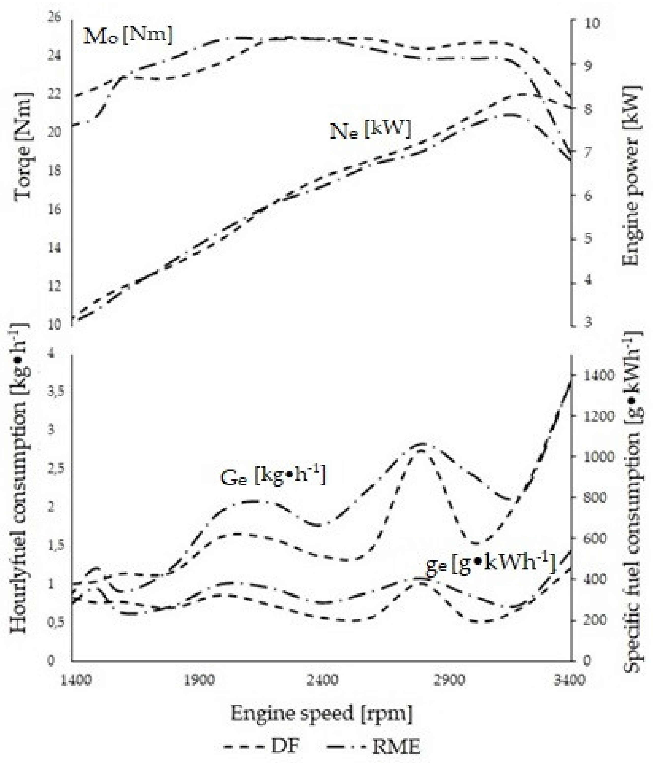
3.1. Engine Characteristic in Full Load Conditions

The prepared engine’s full load characteristics using the two different liquid fuels are shown in Figure 3. Greater torque was achieved with RME in the low-speed range of 1600 to 2100 rpm. In the remainder of the operating field, a better result was obtained with diesel. The difference in favor of RME is due to its higher self-ignition potential, which is due to the chemical composition of this fuel. This is important when using hydraulically operated injectors described above. The physical properties of the liquid fuels used in the experiment are also important due to their influence on the operation of the injectors, which was noted in previous research [61]. The use of diesel fuel allows for more power in the range of higher engine speeds and lower specific fuel consumption in the whole working range. This is due to the higher heating value of diesel fuel (42.6 MJ/kg) compared to RME (38.2 MJ/kg). The authors of a previous study [62] reached similar conclusions, noting the lower value of the in-cylinder pressure and heat release rate. In the highest speed range, where the access of air is significantly reduced by decreasing the volumetric efficiency, higher torque and power were observed using diesel fuel. The engine achieved 10% more maximum power when running on diesel. The authors of similar experimental studies [63], taking into account the measurement of pressure in the cylinder, by determining the mass fraction burned according to Wiebe function, demonstrated the effect of fuel type and engine speed on the value of MBF10–MBF90%. At 1400 and 2000 rpm, a lower value of MBF90% for RME was observed, whereas at 3400 rpm a much higher value for RME was found. The center of combustion was located earlier for diesel at low rpm, whereas at maximum rpm, it was earlier for RME.
The engines used in generator sets operate at specific speeds to achieve the appropriate AC frequency (50 Hz). The remainder of this paper compares the ecological indicators of engine operation at a fixed speed of 1500 rpm due to the widespread use of this setting in generators equipped with CI engines, and similar hourly fuel consumption and torque values.
An exhaust gas sample was taken to identify the exhaust gas composition while determining the full load characteristics of the diesel and biodiesel fueled engine. The results are shown in Figure 4.
The results indicate different emission levels of selected exhaust components when fueled with DF and RME. CO emission in the CI engine is mainly connected with local oxygen deficiency and temperature inside the cylinder. Lower CO concentrations were recorded with DF combustion in the lower rpm range. Above 2400 rpm, CO emissions were lower for RME and decreased with rising engine rotational speed. This is probably related to the oxygen content of RME. In the case analyzed, NOx emissions are the total of NO and NO2 emissions, and the contribution of secondarily formed NO2 was much smaller and did not significantly affect NOx emissions. Large imbalances are characteristic of CI engines, as confirmed in the studies by Koszałka and Hunicz [37] and Golimowski et al. [12]. As speed increased, the NO content in the exhaust gas decreased by 23% for DF and 23.5% for RME. In the whole engine speed range (1400–3400 rpm), lower NO emission values were recorded when burning biodiesel; on average by 14.5%. The difference in NO2 concentration remained approximately constant, averaging 54% in favor of RME. Increasing engine speed reduced PM emissions when the engine was fed DF and RME by 75 and 44%, respectively. Over the entire engine speed range (1400–3400 rpm), PM emissions were lower when the engine was fed RME by an average of 32% (Figure 3). Significant differences were seen in the low-speed range due to the better quality of the combustion process with RME. Reduction in particulate emissions from combustion with RME has been confirmed and extensively studied [64,65] with a reduction in large particulate matter with pure RME, especially under partial-load conditions. The reduction in PM emissions is mainly due to the high oxygen content compared to DF and the absence of aromatic compounds. The oxygen in the fuel aids the combustion process, especially in fuel-rich areas.

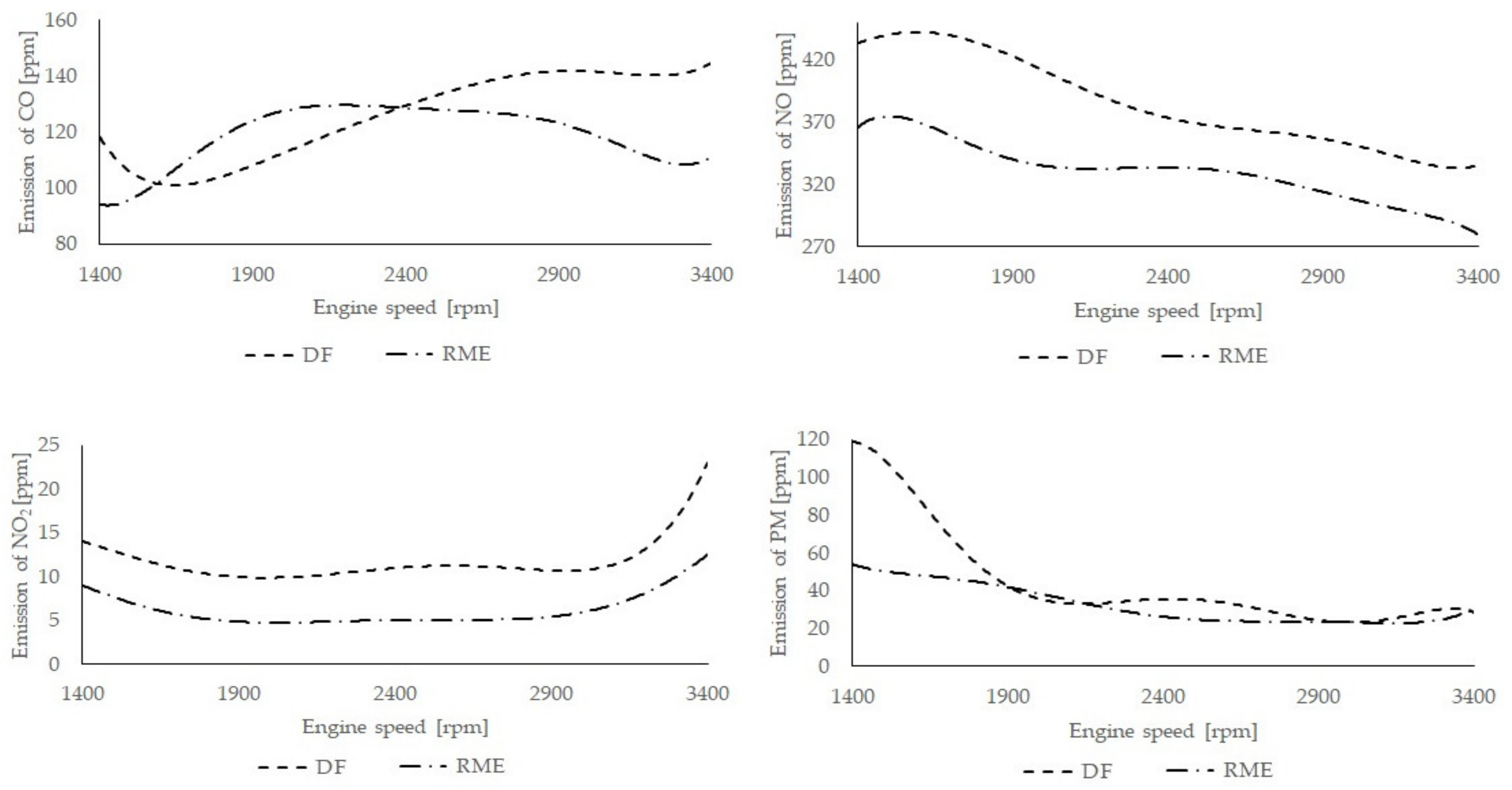
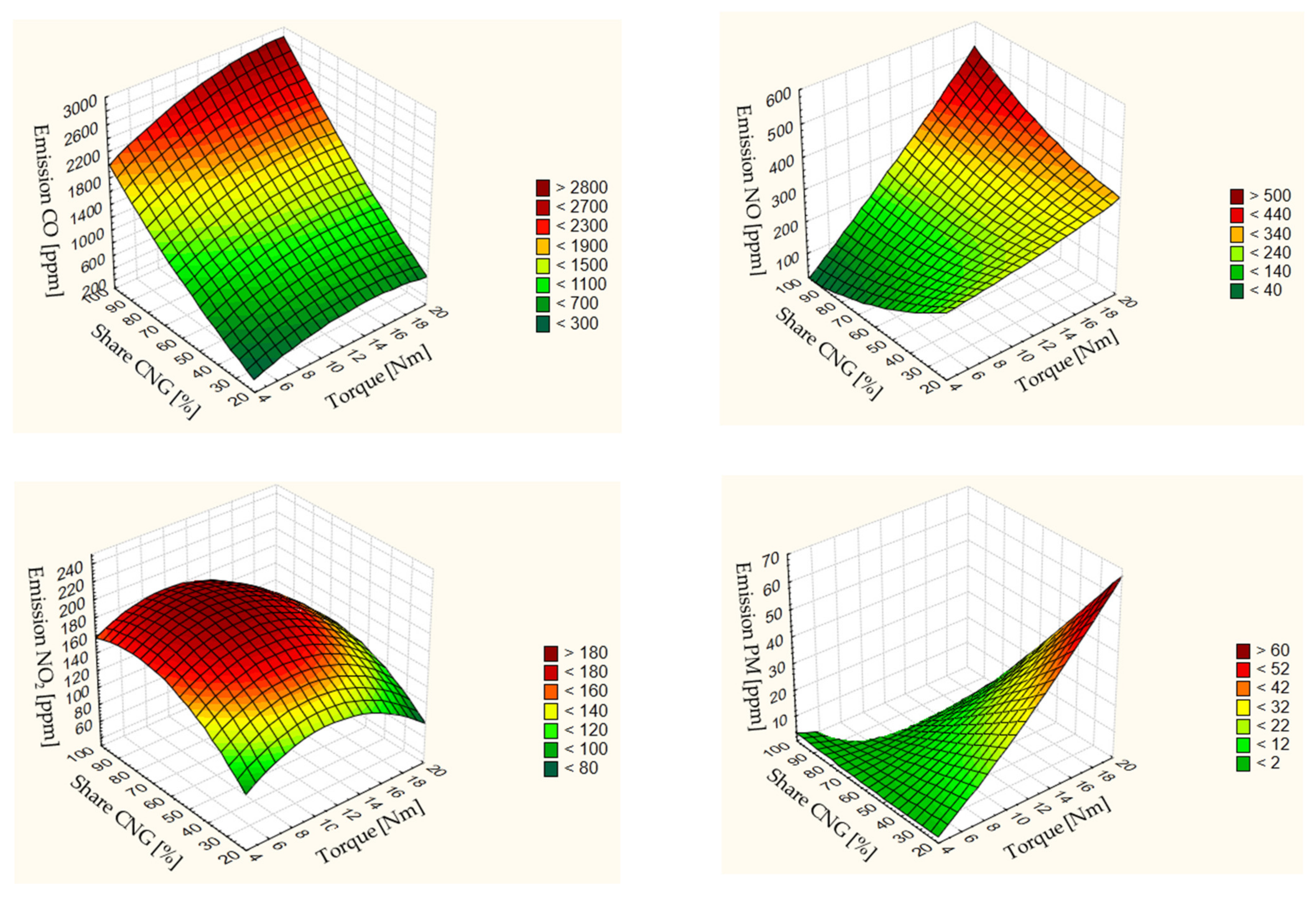
3.2. Emission Characteristic of Dual Fuel Combustion Process

The compiled interpolated maps (Figure 5, Figure 6, Figure 7, Figure 8, Figure 9 and Figure 10) show the concentration of the exhaust gas’s various components as a function of the share of gaseous fuel and the engine load at constant rotational speed (1500 rpm). To better analyze the emissions from the dual-fuel engine, the results of in-cylinder pressure tests under similar conditions are quoted [66], indicating the variation of in-cylinder pressure with respect to the NG share. Additionally, the effect of liquid fuel injection pressure was evaluated, which was negligible for the high NG share, whereas it was significant for the 50% NG share, and accelerated the start of injection (SOI) significance.

3.2.1. CO Emission

By analyzing the CO results, differences shown in the graphs were noted between configurations II, III, V, and VI, which used gases with high methane CH4 content, and configurations I and IV, in which the engine was fueled with liquid propane-butane (LPG). For CNG (II; V) and biogas (III; VI) combustion, CO emissions increased with increasing load and gaseous fuel proportion. Increasing the contribution of gaseous fuel injected into the intake manifold reduces the volumetric efficiency, leading to a reduction in the amount of oxygen in the fresh charge. This results in an oxygen deficit, which likely results in increased CO emissions. Raising the engine load fueled with methane gases (II, III, V, and VI) causes an increase in CO emissions in the analyzed range of operation. The main reason for this is the characteristics of the gases used. The gas supplied to the cylinder is characterized by a slower flame propagation velocity, resulting in a lower charge temperature. LPG engine feed (I; IV) is characterized by a significant decrease in CO emissions with increasing load. This trend has been confirmed by the results of research [51] on a two-cylinder engine with 40% propane; additionally, for comparison the opposite trend was found for pure diesel combustion. This is probably due to increasing charge temperature leading to an acceleration of oxidation reaction, increasing the fraction of LPG when co-combusted with ON, which did not result in significant changes in CO emissions. This is related to the lower stoichiometry of LPG relative to methane. In the case of methane gas fueling, lower emissions were obtained using diesel fuel, whereas in the case of LPG co-combustion, RME had lower emissions.

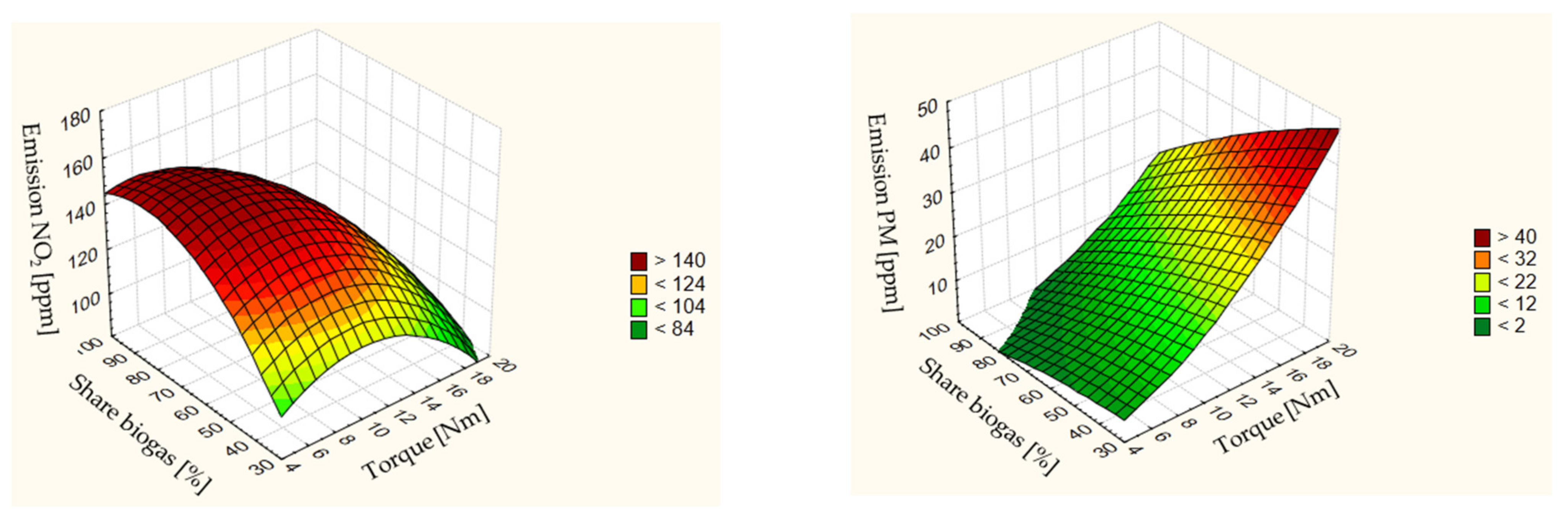
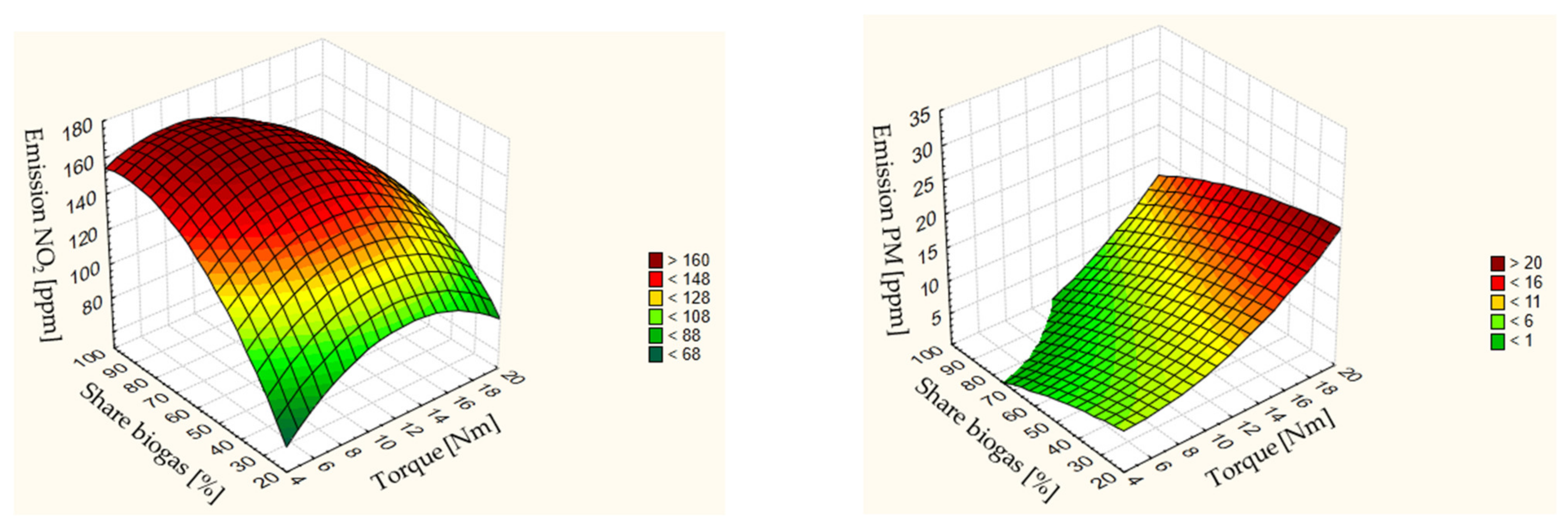
3.2.2. Nitrogen Oxides Emission (NO and NO2)

The NO concentration mainly depends on the value of the charge temperature and the composition of the fuel–air mixture. In all cases, the NO concentration increased with the load growth. This is related to the increase in fuel dose and hence an increase in combustion pressure and temperature. The highest NO emission was noted for LPG fueling at 663 ppm for DF and 680 ppm for RME, respectively. The lowest values using biogas were 249 ppm for the III configuration and 331 ppm for the VI configuration. The gaseous fuel’s laminar flame speed is essential in this case, particularly in configurations I, II, IV, V, in which the highest NO concentration was achieved with the highest share of gaseous fuel. Imran et al. [67] highlighted the significant effect of nitrogen oxide emissions on engine operating point during co-combustion of liquid fuels with CNG.
NO2 emissions followed a similar pattern for all fuel cases except for configuration I. There was a significant decrease in NO2 emissions in the configuration I with an increasing share of gaseous fuel. The trends in maximum values were maintained relative to NO emissions. Minor differences concerning liquid fuel were found with CNG. The highest NO2 emission values occurred for configurations I and IV, at 291 ppm and 285 ppm, respectively.

3.2.3. PM Emission

The obtained trends indicate the particulate matter emission is generated mainly during the diffusive combustion phase and is dependent on changes in engine load. An increase in the time between the beginning and the end of combustion caused by raising the load correlates with increased particulate matter emission. In the case studied, the extension of the combustion time was derived from the increase in the fuel dose. The extremes in the maps were obtained equally in all cases in which only liquid fuel was burned with the highest load. Reduction in PM emission in the whole operation range was obtained by extending the proportion of gaseous fuels. Fuels with a more straightforward chemical structure are more easily decomposed, eliminating soot formation susceptibility, which is well known. Increasing the share of all analyzed gaseous fuels irrespective of load resulted in a significant reduction in PM. A minor reduction in PM was obtained for biogas co-combustion, which was probably related to a decrease in combustion temperature also manifested by the lowest total NO and NO2. Analyzing the effect of liquid fuel type, a lower tendency to PM emission was obtained using RME, which agrees with the results of direct analysis of single combustion of DF and RME. The opposite tendency was obtained for LPG co-firing with a high gas share, which correlates with NO2 emission, and decreased rapidly with LPG share when using DF. In each of these cases, a field of operation was achieved in which PM emissions were close to zero.

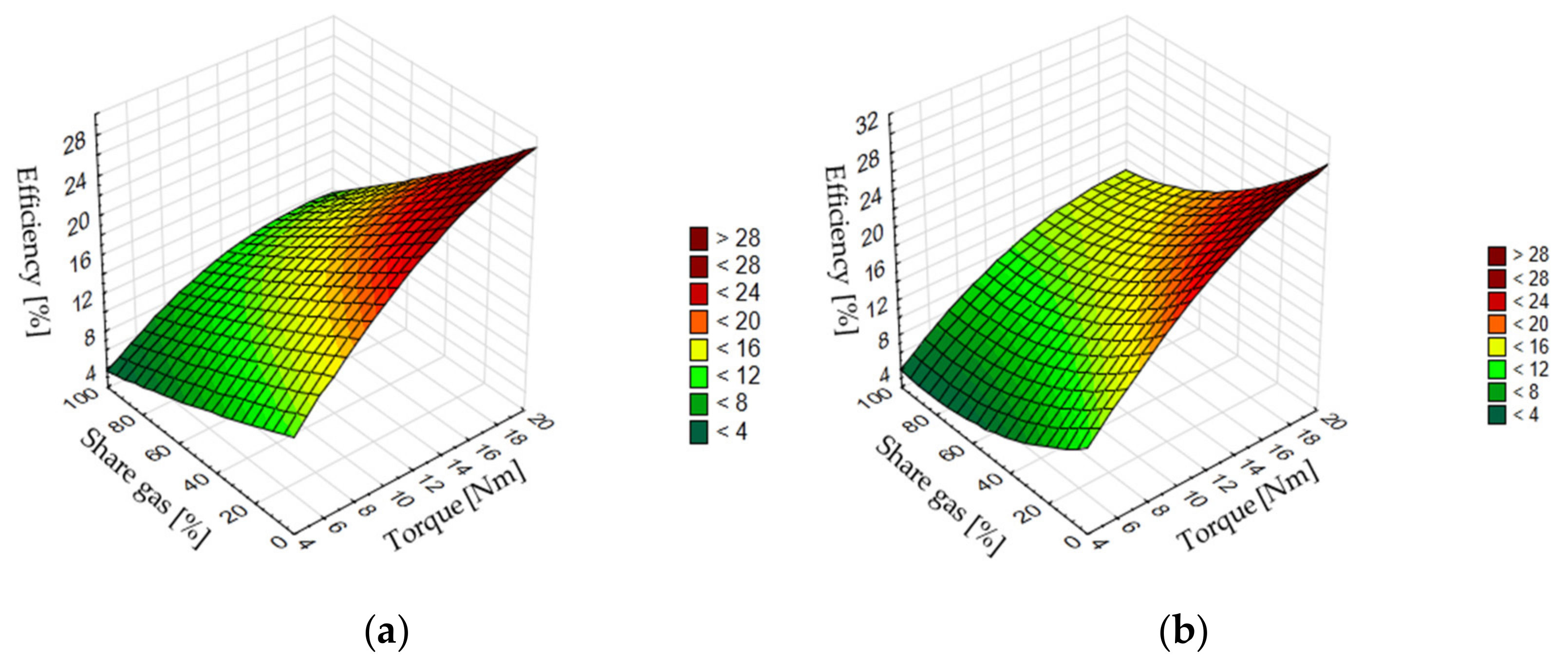
3.3. Cogeneration Set Efficiency Analysis

The cogeneration set’s overall efficiency is determined, among other things, by the efficiency of conversion of the energy contained in the fuel into electricity. The efficiency analysis results of the system are presented in Figure 11, Figure 12 and Figure 13. In all investigated configurations, the efficiency increases with the load. This is probably related to the increase in the mechanical efficiency of the CI engine. The highest efficiency values were achieved for 100% liquid fuel supply at the 20 Nm peak load point. Slightly higher maximum efficiency values were obtained using RME, which has better lubricating properties. Raising the share of gaseous fuel resulted in lower efficiency values of the system. The design of the fuel system with a gas supply to the intake manifold and no charging system is essential; this significantly reduces the volumetric efficiency, resulting in a decrease in generating power. Oxygen deficiency is observed in the carbon monoxide emission maps, whose value for CNG and BG co-combustion increases rapidly with the proportion of gaseous fuel. Volumetric efficiency is particularly important for gaseous fuels due to the higher air requirements for stoichiometric mixture creation. In all cases analyzed, the same trend was achieved as for the analysis of hydrocarbon fuels.

4. Discussion

Previous research [68] indicated an increase in CO emissions during co-combustion of diesel fuel with LPG, at a share of gaseous fuel of 30–40% and an engine load of 12 Nm, in addition to an increase in CO emissions with increasing gas share. The engine was operated in wide open throttle mode; hence the airflow was constant. Only the proportion of gaseous fuel was changed. This causes changes in the calorific value of the fuel–air mixture. The mentioned investigation results confirm the trends described in this publication only for the combustion of diesel and LPG in dual-fuel mode at the lowest engine load of 4.5 Nm. In this case, CO emissions increased by 6% when LPG was added to diesel fuel, and an increase in the share of gas in the liquid fuel (68–92%) resulted in a 24% increase in CO emissions. However, at the highest engine load (20 Nm), an increase in the gas proportion (57–68%) resulted in a 20% reduction in CO emissions. Verma et al. [69] published research results that show an increase in CO emissions when the engine is fueled with a mixture of diesel and CNG gas compared to a single-fuel diesel engine. The results presented in this study are consistent with those reported in the publication mentioned above. The addition of CNG gas to diesel increased CO emissions, multiplied by increasing the dose of gas supplied. The highest CO emissions increase was observed at an engine load of 4.5 Nm and an increase in the gas share of 43–94%, whereas the lowest growth in CO emissions occurred at the highest engine load (20 Nm). This engine load and increase in gas share (25–78%) resulted in a 63% increase in CO emissions.
The use of biogas combined with diesel resulted in increased CO emissions, compounded by increasing the proportion of biogas in the described experiments. The most significant increase in CO emissions occurred at an engine load of 8 Nm (by 58%), whereas the smallest increase (by 51%) occurred at the highest engine load (20 Nm). These relationships are confirmed by the study of Barik [58] and [70]. Barik, in his research, indicates a 16–17% increase in CO emissions [58,70].
The scientific literature uses the total emissions of nitrogen and nitric oxides as the NOx emission rate [41,53,71]. This is related to the fact that nitrogen oxide, in contact with oxygen contained in the air, undergoes an oxidation reaction which results in nitrogen oxide. The research of Dużyński et al., also shows the reduction in NOx emissions in an engine running on a mixture of diesel and LPG gas compared to an engine fueled with pure diesel [68]. This paper’s research results describe the phenomenon of NOx emission change with separation into NO and NO2. The NO emissions decrease with the addition of LPG gas, and the gas addition affects the reduction in NO emissions at the lowest engine loads. The highest reduction in NO emissions with increasing gas dosage (72–100%) was observed at an engine load of 8 Nm, i.e., 74%. However, at higher engine loads (12, 16, and 20 Nm), increasing the gas addition enhanced NO emissions. In contrast, NO2 content increased with increasing the share of LPG supplied to the engine. The highest 48% reduction in NO2 emission was observed at 8 Nm engine load and 72–100% increase in gas dosage. In this paper’s results, when CNG gas was added to diesel fuel at low engine load, NO emissions were reduced. The most significant reduction occurred at the lowest engine load (4.5 Nm) and was 85%. This result was confirmed in Verma’s study for NOx emissions when CNG gas was added to diesel [69]. However, for NO2 emissions, the addition of gas to liquid fuel increased NO2 emissions, which is also confirmed by the studies conducted by Golimowski et al. [12]. In addition, the increase in gas injection dose increased NO2 emissions. Nevertheless, at the highest engine load (20 Nm), an increase in the proportion of CNG gas increased NO2 emissions by only 21%. The use of biogas in a dual-fuel system with diesel results in a reduction in NO emissions and an increase in the share of biogas affected the reduction in NO emissions. The most significant reduction in NO emissions occurred at the lowest engine load (4.5 Nm), i.e., 48%, with an increase in gas dosage of 47–78%. Similar conclusions were reached by Barik and Sivalingam, who in [70] published research results that showed the reduction in NO emissions with the addition of biogas to diesel fuel. Additionally, a decrease in NO content was noted from increasing the share of biogas in the liquid fuel. The most considerable reduction occurred at the highest engine load, i.e., 35% [70].
Regardless of the type of liquid fuel used (DF, RME), increasing the proportion of gaseous fuel resulted in decreased overall efficiency. Published research results confirm these effects. Barik and Murugan, in [58], published the results of research that indicate a 2% reduction in efficiency of a diesel-fueled engine when biogas was added to liquid fuel. Further decreases in efficiency up to 3% were observed when increasing the share of gaseous fuel. However, a previous study published by Barik [70] showed a 5% decrease in engine efficiency when biogas was added to the diesel fuel and a 7% decrease in efficiency with increasing the share of biogas in the fuel mixture [58]. The results of the authors of this paper show a reduction in engine efficiency of 7–16% when biogas was added to methyl esters of higher fatty acids at engine loads of 8–20 Nm. However, at the lowest engine load of 4.5 Nm, the introduction of biogas into the fuel mixture increased engine efficiency by 10%, and increasing the share of gas from 57–73% at the same load increased engine efficiency by 6%.

5. Conclusions

The results of the research described in this publication show that the co-combustion of diesel fuel and methyl esters of higher fatty acids with gaseous fuels (i.e., LPG, CNG, and biogas) causes an increase in the emission of carbon monoxide and nitrogen dioxide and a simultaneous decrease in the emission of nitric oxide and particulate matter. The lowest increase in carbon monoxide emission and nitrogen dioxide occurred during the combustion of diesel fuel with LPG, and was 54% and 44%, respectively. The highest reduction in particulate matter emission (by 57%) was also observed during the combustion of the same fuel mixture. However, the most favorable configuration of fuels in relation to the level of PM emissions was found to be RME combustion with different BG values. The greatest reduction in nitric oxide emission (by 37%) was recorded during diesel fuel combustion with biogas additive. The smallest increase in the emission of carbon monoxide and nitrogen dioxide was noted during the combustion of methyl esters of higher fatty acids (RME) with LPG, by 73% and 52% on average. For the same fuel configuration, the most significant reduction in particulate matter emissions occurred, averaging 77%. The most significant reduction in nitrogen oxide emissions occurred with the injection of biogas into RME, which averaged 33%.
The efficiency of the cogeneration system was lowered with each addition of gaseous fuel. A lower decrease in efficiency was recorded when using RME with gaseous fuels. A minor decrease in engine efficiency occurred when biogas was introduced into the combustion chamber of engines fueled with DF and RME, and amounted to, respectively, 12% and 8% on average. This configuration is particularly advantageous in the range of medium and high generator loads. Given the relationship between CO, NO, NO2, and PM emissions and the efficiency value of a dual-fuel engine, the RME configuration from BG appears to be the most appropriate for unmodified power generators. Based on the research results obtained based on the use of six fuel configurations, preparations are being made for detailed thermodynamic analyses of selected fuel configurations (primarily RME and BG).

Author Contributions

Conceptualization, W.G. (Weronika Gracz), W.G. (Wojciech Golimowski) and P.K.; methodology, W.G. (Weronika Gracz), W.G. (Wojciech Golimowski) and P.K.; validation, W.G. (Wojciech Golimowski), D.M. and P.K.; formal analysis, W.G. (Weronika Gracz) and W.G. (Wojciech Golimowski); investigation, W.G. (Weronika Gracz), D.M., W.G. (Wojciech Golimowski) and P.K.; resources, apertures and test stand, W.G. (Weronika Gracz), D.M., W.G. (Wojciech Golimowski), M.S. and P.K.; data curation, W.G. (Weronika Gracz), D.M., W.G. (Wojciech Golimowski), and P.K.; writing—original draft preparation, W.G. (Weronika Gracz), D.M., W.G. (Wojciech Golimowski), F.S. and P.K.; writing—review and editing, W.G. (Weronika Gracz), W.G. (Wojciech Golimowski), M.S., J.W. and P.K.; visualization, W.G. (Weronika Gracz) and W.G. (Wojciech Golimowski); supervision, W.G. (Wojciech Golimowski) and P.K.; funding acquisition, P.K. and J.W. All authors have read and agreed to the published version of the manuscript.

Funding

The APC Funded from the ‘Excellent science’ program of the Ministry of Education and Science as a part of the contract no. DNK/SP/465641/2020 “The role of the agricultural engineering and environmental engineering in the sustainable agriculture development”.

Institutional Review Board Statement

Not applicable.

Informed Consent Statement

Not applicable.

Data Availability Statement

Data available from the authors.

Conflicts of Interest

The authors declare no conflict of interest. The funders had no role in the design of the study; in the collection, analyses, or interpretation of data; in the writing of the manuscript, or in the decision to publish the results.

The List of Symbols and Acronyms

ACalternating current
BGbiogas
CH4methane
CIcompression ignition
CNGcompressed natural gas
COcarbon monoxide
CO2carbon dioxide
DFdiesel fuel
Gehourly fuel consumption, [kg·h−1]
gespecific fuel consumption, [g·kWh−1]
H2Shydrogen sulfide
HChydrocarbons
LNGnatural gas in liquid form
LPGliquefied petroleum gas
Motorque, [Nm]
nengine speed, [rpm]
ƞoverall efficiency of the cogeneration unit, [%]
Nepower of the internal combustion engine, [kW]
NOnitric oxide
NO2nitrogen dioxide
NOxoxides of nitrogen
O2oxygen
PMparticulate matter
RESrenewable energy sources
RMErape methyl esters of higher fatty acids
SIspark ignition
SOIstart of injection
SO2sulfur dioxide
SO3sulfur trioxide

References

  1. Ghiasi, M.; Esmaeilnamazi, S.; Ghiasi, R.; Fathi, M. Role of Renewable Energy Sources in Evaluating Technical and Economic Efficiency of Power Quality. Technol. Econ. Smart Grids Sustain. Energy 2020, 5, 1. [Google Scholar] [CrossRef] [Green Version]
  2. Rathi, R.; Prakash, C.; Singh, S.; Krolczyk, G.; Pruncu, C.I. Measurement and Analysis of Wind Energy Potential Using Fuzzy Based Hybrid MADM Approach. Energy Rep. 2020, 6, 228–237. [Google Scholar] [CrossRef]
  3. Hunicz, J.; Matijošius, J.; Rimkus, A.; Kilikevičius, A.; Kordos, P.; Mikulski, M. Efficient Hydrotreated Vegetable Oil Combustion under Partially Premixed Conditions with Heavy Exhaust Gas Recirculation. Fuel 2020, 268, 117350. [Google Scholar] [CrossRef]
  4. Duda, K.; Wierzbicki, S.; Śmieja, M.; Mikulski, M. Comparison of Performance and Emissions of a CRDI Diesel Engine Fuelled with Biodiesel of Different Origin. Fuel 2018, 212, 202–222. [Google Scholar] [CrossRef]
  5. Zhao, Y.; Damgaard, A.; Liu, S.; Chang, H.; Christensen, T.H. Bioethanol from Corn Stover—Integrated Environmental Impacts of Alternative Biotechnologies. Resour. Conserv. Recycl. 2020, 155, 104652. [Google Scholar] [CrossRef]
  6. Caligiuri, C.; Renzi, M.; Bietresato, M.; Baratieri, M. Experimental Investigation on the Effects of Bioethanol Addition in Diesel-Biodiesel Blends on Emissions and Performances of a Micro-Cogeneration System. Energy Convers. Manag. 2019, 185, 55–65. [Google Scholar] [CrossRef]
  7. Hawrot-Paw, M.; Koniuszy, A.; Zając, G.; Szyszlak-Bargłowicz, J.; Jaklewicz, J. Production of Second Generation Bioethanol from Straw during Simultaneous Microbial Saccharification and Fermentation. Arch. Environ. Prot. 2020, 46, 47–52. [Google Scholar] [CrossRef]
  8. Maj, G.; Piekarski, W.; Kowalczyk-Juśko, A.; Łukaszczyk, A. Odpady z sektora rolno-spożywczego, komunalnego i upraw celowych jako źródło biogazu. Przemysł Chem. 2014, 93, 732–736. [Google Scholar] [CrossRef]
  9. Kozłowski, K.; Pietrzykowski, M.; Czekała, W.; Dach, J.; Kowalczyk-Juśko, A.; Jóźwiakowski, K.; Brzoski, M. Energetic and Economic Analysis of Biogas Plant with Using the Dairy Industry Waste. Energy 2019, 183, 1023–1031. [Google Scholar] [CrossRef]
  10. Postawa, K.; Szczygieł, J.; Wrzesińska-Jędrusiak, E.; Klimek, K.; Kułażyński, M. The Pump-Mixed Anaerobic Digestion of Pig Slurry: New Technology and Mathematical Modeling. Waste Manag. 2021, 123, 111–119. [Google Scholar] [CrossRef] [PubMed]
  11. Mustafi, N.N.; Raine, R.R. A Study of the Emissions of a Dual Fuel Engine Operating with Alternative Gaseous Fuels; SAE International: Warrendale, PA, USA, 2008. [Google Scholar]
  12. Golimowski, W.; Krzaczek, P.; Marcinkowski, D.; Gracz, W.; Wałowski, G. Impact of Biogas and Waste Fats Methyl Esters on NO, NO2, CO, and PM Emission by Dual Fuel Diesel Engine. Sustainability 2019, 11, 1799. [Google Scholar] [CrossRef] [Green Version]
  13. Zhou, H.; Zhao, H.-W.; Huang, Y.-P.; Wei, J.-H.; Peng, Y.-H. Effects of Injection Timing on Combustion and Emission Performance of Dual-Fuel Diesel Engine under Low to Medium Load Conditions. Energies 2019, 12, 2349. [Google Scholar] [CrossRef] [Green Version]
  14. Owczuk, M.; Matuszewska, A.; Kruczyński, S.; Kamela, W. Evaluation of Using Biogas to Supply the Dual Fuel Diesel Engine of an Agricultural Tractor. Energies 2019, 12, 1071. [Google Scholar] [CrossRef] [Green Version]
  15. Rimkus, A.; Stravinskas, S.; Matijošius, J. Comparative Study on the Energetic and Ecologic Parameters of Dual Fuels (Diesel–NG and HVO–Biogas) and Conventional Diesel Fuel in a CI Engine. Appl. Sci. 2020, 10, 359. [Google Scholar] [CrossRef] [Green Version]
  16. Makareviciene, V.; Sendzikiene, E.; Pukalskas, S.; Rimkus, A.; Vegneris, R. Performance and Emission Characteristics of Biogas Used in Diesel Engine Operation. Energy Convers. Manag. 2013, 75, 224–233. [Google Scholar] [CrossRef]
  17. Lebedevas, S.; Čepaitis, T. Parametric Analysis of the Combustion Cycle of a Diesel Engine for Operation on Natural Gas. Sustainability 2021, 13, 2773. [Google Scholar] [CrossRef]
  18. Raslavičius, L.; Keršys, A.; Mockus, S.; Keršienė, N.; Starevičius, M. Liquefied Petroleum Gas (LPG) as a Medium-Term Option in the Transition to Sustainable Fuels and Transport. Renew. Sustain. Energy Rev. 2014, 32, 513–525. [Google Scholar] [CrossRef]
  19. Rosha, P.; Dhir, A.; Mohapatra, S.K. Influence of Gaseous Fuel Induction on the Various Engine Characteristics of a Dual Fuel Compression Ignition Engine: A Review. Renew. Sustain. Energy Rev. 2018, 82, 3333–3349. [Google Scholar] [CrossRef]
  20. Aydin, M.; Irgin, A.; Çelik, M.B. The Impact of Diesel/LPG Dual Fuel on Performance and Emissions in a Single Cylinder Diesel Generator. Appl. Sci. 2018, 8, 825. [Google Scholar] [CrossRef] [Green Version]
  21. Boretti, A. Advances in Diesel-LNG Internal Combustion Engines. Appl. Sci. 2020, 10, 1296. [Google Scholar] [CrossRef] [Green Version]
  22. Szczygieł, I.; Stanek, W.; Szargut, J. Application of the Stirling Engine Driven with Cryogenic Exergy of LNG (Liquefied Natural Gas) for the Production of Electricity. Energy 2016, 105, 25–31. [Google Scholar] [CrossRef]
  23. Tang, Q.; Fu, J.; Liu, J.; Zhou, F.; Yuan, Z.; Xu, Z. Performance Improvement of Liquefied Natural Gas (LNG) Engine through Intake Air Supply. Appl. Therm. Eng. 2016, 103, 1351–1361. [Google Scholar] [CrossRef]
  24. Yan, F.; Xu, L.; Wang, Y. Application of Hydrogen Enriched Natural Gas in Spark Ignition IC Engines: From Fundamental Fuel Properties to Engine Performances and Emissions. Renew. Sustain. Energy Rev. 2018, 82, 1457–1488. [Google Scholar] [CrossRef]
  25. Jamrozik, A.; Tutak, W.; Grab-Rogaliński, K. An Experimental Study on the Performance and Emission of the Diesel/CNG Dual-Fuel Combustion Mode in a Stationary CI Engine. Energies 2019, 12, 3857. [Google Scholar] [CrossRef] [Green Version]
  26. Monsalve-Serrano, J.; Belgiorno, G.; Di Blasio, G.; Guzmán-Mendoza, M. 1D Simulation and Experimental Analysis on the Effects of the Injection Parameters in Methane–Diesel Dual-Fuel Combustion. Energies 2020, 13, 3734. [Google Scholar] [CrossRef]
  27. Gómez Montoya, J.P.; Olsen, D.B.; Amell, A.A. Engine Operation Just above and below the Knocking Threshold, Using a Blend of Biogas and Natural Gas. Energy 2018, 153, 719–725. [Google Scholar] [CrossRef]
  28. Haydargil, D.; Abuşoğlu, A. A Comparative Thermoeconomic Cost Accounting Analysis and Evaluation of Biogas Engine-Powered Cogeneration. Energy 2018, 159, 97–114. [Google Scholar] [CrossRef]
  29. Bora, B.J.; Saha, U.K. Experimental Evaluation of a Rice Bran Biodiesel—Biogas Run Dual Fuel Diesel Engine at Varying Compression Ratios. Renew. Energy 2016, 87, 782–790. [Google Scholar] [CrossRef]
  30. Othman, M.F.; Adam, A.; Najafi, G.; Mamat, R. Green Fuel as Alternative Fuel for Diesel Engine: A Review. Renew. Sustain. Energy Rev. 2017, 80, 694–709. [Google Scholar] [CrossRef]
  31. Liu, Z.; Yang, L.; Song, E.; Wang, J.; Zare, A.; Bodisco, T.A.; Brown, R.J. Development of a Reduced Multi-Component Combustion Mechanism for a Diesel/Natural Gas Dual Fuel Engine by Cross-Reaction Analysis. Fuel 2021, 293, 120388. [Google Scholar] [CrossRef]
  32. Jafari, M.; Verma, P.; Bodisco, T.A.; Zare, A.; Surawski, N.C.; Borghesani, P.; Stevanovic, S.; Guo, Y.; Alroe, J.; Osuagwu, C.; et al. Multivariate Analysis of Performance and Emission Parameters in a Diesel Engine Using Biodiesel and Oxygenated Additive. Energy Convers. Manag. 2019, 201, 112183. [Google Scholar] [CrossRef]
  33. Hossain, F.M.; Nabi, M.D.N.; Rahman, M.D.M.; Bari, S.; Van, T.C.; Rahman, S.M.A.; Rainey, T.J.; Bodisco, T.A.; Suara, K.; Ristovski, Z.; et al. Experimental Investigation of Diesel Engine Performance, Combustion and Emissions Using a Novel Series of Dioctyl Phthalate (DOP) Biofuels Derived from Microalgae. Energies 2019, 12, 1964. [Google Scholar] [CrossRef] [Green Version]
  34. Hunicz, J.; Krzaczek, P. Detailed Speciation of Emissions from Low-Temperature Combustion in a Gasoline HCCI Engine. Pol. J. Environ. Stud. 2016, 25, 137–145. [Google Scholar] [CrossRef]
  35. Mikulski, M.; Ambrosewicz-Walacik, M.; Hunicz, J.; Nitkiewicz, S. Combustion Engine Applications of Waste Tyre Pyrolytic Oil. Prog. Energy Combust. Sci. 2021, 85, 100915. [Google Scholar] [CrossRef]
  36. Gracz, W.; Czechlowski, M.; Marcinkowski, D.; Golimowski, W.; Pochwatka, P. The Impact of the Temperature of Rapeseed Oil Methyl Esters on Nitrogen Oxides Emissions. E3S Web Conf. 2020, 171, 01002. [Google Scholar] [CrossRef]
  37. Koszalka, G.; Hunicz, J. Detailed Speciation of Emissions from a Diesel Engine Fuelled with Canola Methyl Ester. MATEC Web Conf. 2018, 234, 03005. [Google Scholar] [CrossRef]
  38. Rašić, D.; Oprešnik, S.R.; Seljak, T.; Vihar, R.; Baškovič, U.Ž.; Wechtersbach, T.; Katrašnik, T. RDE-Based Assessment of a Factory Bi-Fuel CNG/Gasoline Light-Duty Vehicle. Atmos. Environ. 2017, 167, 523–541. [Google Scholar] [CrossRef]
  39. Knothe, G.; Krahl, J.; Gerpen, J.V. (Eds.) 7—Exhaust Emissions. In The Biodiesel Handbook, 2nd ed.; Academic Press and AOCS Press: Cambridge, MA, USA, 2010; pp. 253–298. ISBN 978-1-893997-62-2. [Google Scholar]
  40. Hunicz, J.; Krzaczek, P.; Gęca, M.; Rybak, A.; Mikulski, M. Comparative Study of Combustion and Emissions of Diesel Engine Fuelled with FAME and HVO. Combust. Engines 2021, 184, 72–78. [Google Scholar] [CrossRef]
  41. Wasilewski, J.; Krzaczek, P. Emission of toxic compounds from combustion of biodiesel: A report from studies. Przem. Chem. 2014, 93, 343–346. [Google Scholar] [CrossRef]
  42. Duda, K.; Wierzbicki, S.; Mikulski, M.; Konieczny, Ł.; Łazarz, B.; Letuń-Łątka, M. Emissions from a medium-duty crdi engine fuelled with diesel-biodiesel blends. Transp. Probl. 2021, 16, 39–49. [Google Scholar] [CrossRef]
  43. Thapa, S.; Indrawan, N.; Bhoi, P.R. An Overview on Fuel Properties and Prospects of Jatropha Biodiesel as Fuel for Engines. Environ. Technol. Innov. 2018, 9, 210–219. [Google Scholar] [CrossRef]
  44. Utlu, Z.; Koçak, M.S. The Effect of Biodiesel Fuel Obtained from Waste Frying Oil on Direct Injection Diesel Engine Performance and Exhaust Emissions. Renew. Energy 2008, 33, 1936–1941. [Google Scholar] [CrossRef]
  45. Dorado, M. Exhaust Emissions from a Diesel Engine Fueled with Transesterified Waste Olive Oil⋆. Fuel 2003, 82, 1311–1315. [Google Scholar] [CrossRef]
  46. Ozsezen, A.N.; Canakci, M. The Emission Analysis of an IDI Diesel Engine Fueled with Methyl Ester of Waste Frying Palm Oil and Its Blends. Biomass Bioenergy 2010, 34, 1870–1878. [Google Scholar] [CrossRef]
  47. Usta, N.; Öztürk, E.; Can, Ö.; Conkur, E.S.; Nas, S.; Çon, A.H.; Can, A.Ç.; Topcu, M. Combustion of Biodiesel Fuel Produced from Hazelnut Soapstock/Waste Sunflower Oil Mixture in a Diesel Engine. Energy Convers. Manag. 2005, 46, 741–755. [Google Scholar] [CrossRef]
  48. Ulusoy, Y.; Tekin, Y.; Cetinkaya, M.; Karaosmanoglu, F. The Engine Tests of Biodiesel from Used Frying Oil. Energy Sources 2004, 26, 927–932. [Google Scholar] [CrossRef]
  49. Kakaee, A.-H.; Nasiri-Toosi, A.; Partovi, B.; Paykani, A. Effects of Piston Bowl Geometry on Combustion and Emissions Characteristics of a Natural Gas/Diesel RCCI Engine. Appl. Therm. Eng. 2016, 102, 1462–1472. [Google Scholar] [CrossRef]
  50. Fraioli, V.; Mancaruso, E.; Migliaccio, M.; Vaglieco, B.M. Ethanol Effect as Premixed Fuel in Dual-Fuel CI Engines: Experimental and Numerical Investigations. Appl. Energy 2014, 119, 394–404. [Google Scholar] [CrossRef]
  51. Saleh, H. Effect of Variation in LPG Composition on Emissions and Performance in a Dual Fuel Diesel Engine. Fuel 2008, 87, 3031–3039. [Google Scholar] [CrossRef]
  52. Ryu, K. Effects of Pilot Injection Timing on the Combustion and Emissions Characteristics in a Diesel Engine Using Biodiesel–CNG Dual Fuel. Appl. Energy 2013, 111, 721–730. [Google Scholar] [CrossRef]
  53. Di Blasio, G.; Belgiorno, G.; Beatrice, C. Effects on Performances, Emissions and Particle Size Distributions of a Dual Fuel (Methane-Diesel) Light-Duty Engine Varying the Compression Ratio. Appl. Energy 2017, 204, 726–740. [Google Scholar] [CrossRef]
  54. Ianniello, R.; Di Blasio, G.; Marialto, R.; Beatrice, C.; Cardone, M. Assessment of Direct Injected Liquefied Petroleum Gas-Diesel Blends for Ultra-Low Soot Combustion Engine Application. Appl. Sci. 2020, 10, 4949. [Google Scholar] [CrossRef]
  55. Beatrice, C.; Denbratt, I.; Blasio, G.D.; Luca, G.D.; Ianniello, R.; Saccullo, M. Experimental Assessment on Exploiting Low Carbon Ethanol Fuel in a Light-Duty Dual-Fuel Compression Ignition Engine. Appl. Sci. 2020, 10, 7182. [Google Scholar] [CrossRef]
  56. Qian, Y.; Sun, S.; Ju, D.; Shan, X.; Lu, X. Review of the State-of-the-Art of Biogas Combustion Mechanisms and Applications in Internal Combustion Engines. Renew. Sustain. Energy Rev. 2017, 69, 50–58. [Google Scholar] [CrossRef]
  57. Barik, D.; Vijayaraghavan, R. Effects of Waste Chicken Fat Derived Biodiesel on the Performance and Emission Characteristics of a Compression Ignition Engine. Int. J. Ambient. Energy 2018, 41, 88–97. [Google Scholar] [CrossRef]
  58. Barik, D.; Murugan, S. Investigation on Combustion Performance and Emission Characteristics of a DI (Direct Injection) Diesel Engine Fueled with Biogas–Diesel in Dual Fuel Mode. Energy 2014, 72, 760–771. [Google Scholar] [CrossRef]
  59. Bhuiya, M.M.K.; Rasul, M.G.; Khan, M.M.K.; Ashwath, N.; Azad, A.K.; Hazrat, M.A. Prospects of 2nd Generation Biodiesel as a Sustainable Fuel—Part 2: Properties, Performance and Emission Characteristics. Renew. Sustain. Energy Rev. 2016, 55, 1129–1146. [Google Scholar] [CrossRef]
  60. Barik, D.; Murugan, S. Experimental Investigation on the Behavior of a DI Diesel Engine Fueled with Raw Biogas–Diesel Dual Fuel at Different Injection Timing. J. Energy Inst. 2016, 89, 373–388. [Google Scholar] [CrossRef]
  61. Krzaczek, P.; Rybak, A.; Bochniak, A. The Impact of Selected Biofuels on the Performance Parameters of the Common Rail Power System in the Utility Engine. MATEC Web Conf. 2018, 234, 03004. [Google Scholar] [CrossRef]
  62. Golovitchev, V.I.; Yang, J. The Construction of the Combustion Models for RME Bio-Diesel Fuel for ICE Application. Environ. Sci. 2008, 241–255. [Google Scholar]
  63. Di Iorio, S.; Magno, A.; Mancaruso, E.; Vaglieco, B.M.; Arnone, L.; Dal Bello, L. Engine Performance and Emissions of a Small Diesel Engine Fueled with Various Diesel/RME Blends. In Proceedings of the SAE/JSAE 2014 Small Engine Technology Conference & Exhibition, Pisa, Italy, 18–24 November 2014. [Google Scholar]
  64. Mayer, A.; Czerwinski, J.; Wyser, M.; Mattrel, P.; Heitzer, A. Impact of RME/Diesel Blends on Particle Formation, Particle Filtration and PAH Emissions. In Proceedings of the SAE 2005 World Congress & Exhibition, Detroit, MI, USA, 11–14 April 2005. [Google Scholar]
  65. Merkisz, J.; Kozak, M.; Pielecha, J.; Andrzejewski, M. The Influence of Application of Different Diesel Fuel-RME Blends on PM Emissions from a Diesel Engine. Combust. Engines 2012, 148, 35–39. [Google Scholar]
  66. Kozarac, D.; Sremec, M.; Bozic, M.; Vucetic, A. The Performance and Emissions of a Conventional Natural Gas/Diesel Dual Fuel Engine at Various Operating Conditions. In Proceedings of the 2019 WCX SAE World Congress Experience, Detroit, MI, USA, 9–11 April 2019. [Google Scholar]
  67. Imran, S.; Emberson, D.R.; Diez, A.; Wen, D.S.; Crookes, R.J.; Korakianitis, T. Natural Gas Fueled Compression Ignition Engine Performance and Emissions Maps with Diesel and RME Pilot Fuels. Appl. Energy 2014, 124, 354–365. [Google Scholar] [CrossRef] [Green Version]
  68. Dużyński, A. (Ed.) Silniki Gazowe: Wybrane Zagadnienia; Monografie/Politechnika Częstochowska; Wydawnistwo Politechniki Częstochowskiej: Częstochowa, Poland, 2010; ISBN 978-83-7193-461-2. [Google Scholar]
  69. Verma, S.; Das, L.M.; Bhatti, S.S.; Kaushik, S.C. A Comparative Exergetic Performance and Emission Analysis of Pilot Diesel Dual-Fuel Engine with Biogas, CNG and Hydrogen as Main Fuels. Energy Convers. Manag. 2017, 151, 764–777. [Google Scholar] [CrossRef]
  70. Barik, D.; Sivalingam, M. Performance and Emission Characteristics of a Biogas Fueled DI Diesel Engine. In Proceedings of the SAE/KSAE 2013 International Powertrains, Fuels & Lubricants Meeting, Seoul, Korea, 21–23 October 2013. [Google Scholar]
  71. Liu, X.; Wang, H.; Zheng, Z.; Yao, M. Numerical Investigation on the Combustion and Emission Characteristics of a Heavy-Duty Natural Gas-Diesel Dual-Fuel Engine. Fuel 2021, 300, 120998. [Google Scholar] [CrossRef]
Figure 1. Research test stand and measuring system layout where: 1—Test stand management system; 2—Brake; 3—Engine; 4—Air filter; 5—Liquid fuel tank with fuel consumption measuring system; 6—Gaseous fuel tank with reducer; 7—Data acquisition system; 8—Gaseous fuel injector rail; 9—Gaseous fuel mass flow meter; 10—Gaseous exhaust components analyzer; 11—Particular matter analyzer; 12—Oxygen sensor; 13—Temperature sensor; 14. Grid.
Energies 14 03388 g001
Figure 2. The share of liquid fuel in the fuel dose depending on the engine load.
Energies 14 03388 g002
Figure 3. Characteristics of the full load of the tested engine fueled with the tested fuels.
Energies 14 03388 g003
Figure 4. CO, NO, NO2, and PM emission (ppm) at full engine load as a function of rotational speed.
Energies 14 03388 g004
Figure 5. Emission of CO, NO, NO2, and PM in the mixture of DF and LPG at variable load.
Energies 14 03388 g005
Figure 6. Emission of CO, NO, NO2, and PM in the mixture of DF and CNG at variable load.
Energies 14 03388 g006
Figure 7. Emission of CO, NO, NO2, and PM in the mixture of DF and BG at variable load.
Energies 14 03388 g007aEnergies 14 03388 g007b
Figure 8. Emission of CO, NO, NO2, and PM in the mixture of RME and LPG at variable load.
Energies 14 03388 g008
Figure 9. Emission of CO, NO, NO2, and PM in the mixture of RME and CNG at variable load.
Energies 14 03388 g009
Figure 10. Emission of CO, NO, NO2, and PM in the mixture of RME and BG at variable load.
Energies 14 03388 g010aEnergies 14 03388 g010b
Figure 11. Efficiency of the cogeneration unit for the mixtures: (a) DF + LPG and (b) RME + LPG.
Energies 14 03388 g011
Figure 12. Efficiency of the cogeneration unit for the mixtures: (a) DF + CNG and (b) RME + CNG.
Energies 14 03388 g012
Figure 13. Efficiency of the cogeneration unit for the mixtures: (a) DF + BG and (b) RME + BG.
Energies 14 03388 g013
Table 1. Technical data of the Yanmar 2TNV70 engine.
Engine Model2TNV70
Ignition systemCI
Air systemNaturally Aspirated
Cylinder number2
Displacement0.57 L
Engine power3400 obr·min−1
9.76 kW
Type of coolingLiquid cooling
Table 2. Asynchronous motor OMT1-160M2.
ModelOMT1-160M2
Rated power15 [kW]
Maximum speed3400 [rpm]
Rated current400/690 [V]
20.4/11.8 [A]
Rated torque [Nm]36
Table 3. Fatty acid profile of rapeseed oil methyl esters.
Names of Higher Fatty Acids Determined[%]
Myristic(C 14:0)-
Palmitic(C 16:0)0.55
Palmitoleic(C 16:1)4.6
Stearic(C 18:0)1.63
Oleic(C 18:1)61.96
Linoleic(C 18:2)18.11
Linolenic(C 18:3)9.6
Arachidonic(C 20:0)0.57
Eikosaniod(C 20:1)1.43
Others 1.55
Table 4. Physical properties of liquid and gaseous fuels.
Fuel PropertiesRMEDFBGLPG/CNG
Viscosity 40 °C (mm2·s−1)4.792.91--
Density 15 °C (kg·m−3)884.9836.71.250.7/0.8 *
Calorific value (MJ/kg)38.242.617.645.93/50.05
* Data from www.e-petrol.pl and the Polish Chamber of Liquid Fuels.
Table 5. Chemical composition of biogas.
GasContentMeasurement Error
Hydrogen sulfideH2S28 ppm±10%
MethaneCH459.9% (v/v)±3%
Carbon dioxideCO241.7% (v/v)±3%
OxygenO20.7% (v/v)±1%
Table 6. Chemical composition of biogas.
No.Test Configuration
IDF + LPG
IIDF + CNG
IIIDF + BG
IVRME + LPG
VRME + CNG
VIRME + BG
Publisher’s Note: MDPI stays neutral with regard to jurisdictional claims in published maps and institutional affiliations.

