
Method of Limiting Shaft Voltages in AC Electric Machines


Abstract
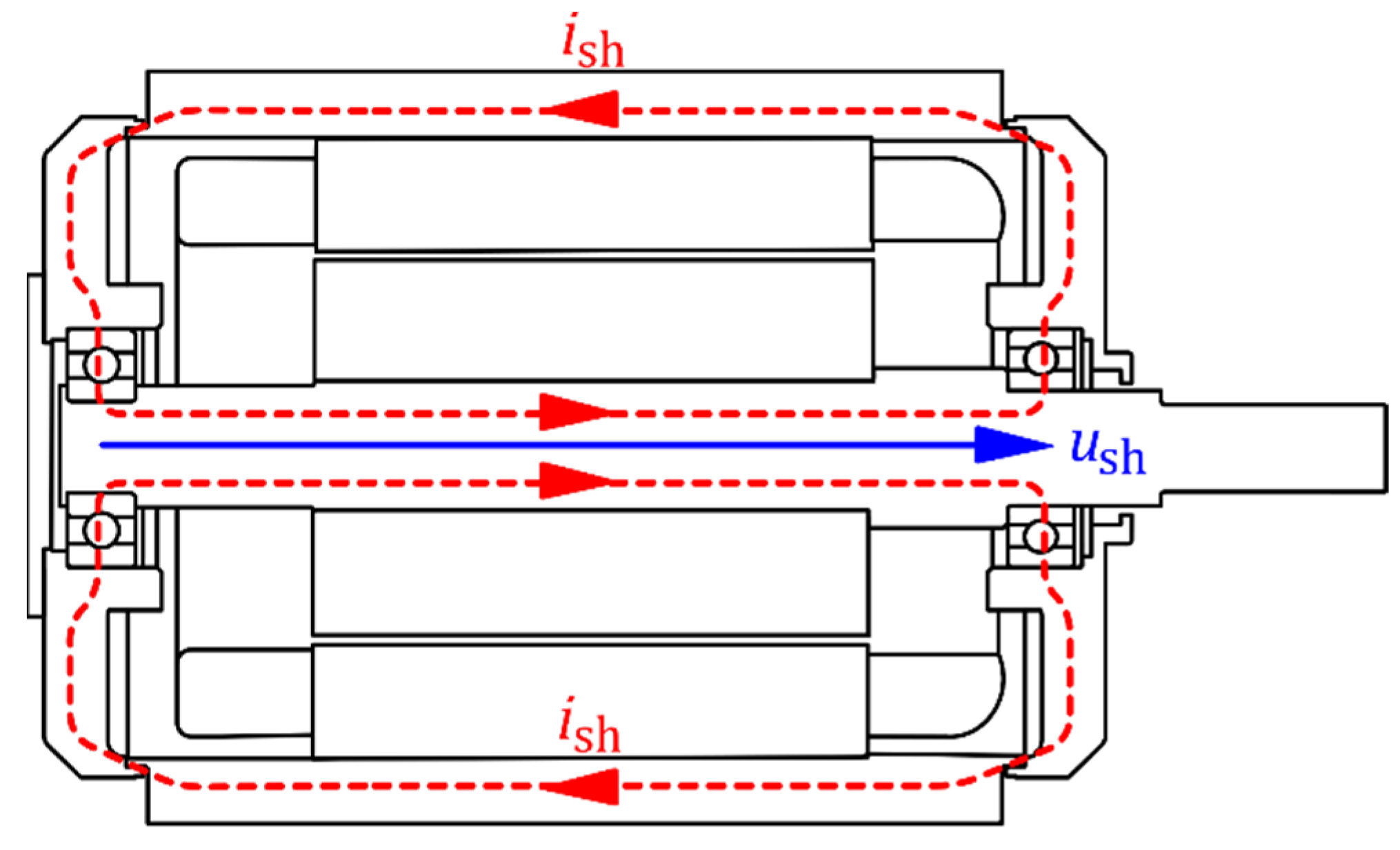
1. Introduction
- Degradation of the main and turn-to-turn insulation of the stator winding.
- Rotor failures (e.g., broken rotor bars in an induction machine, demagnetization of rotor permanent magnets).
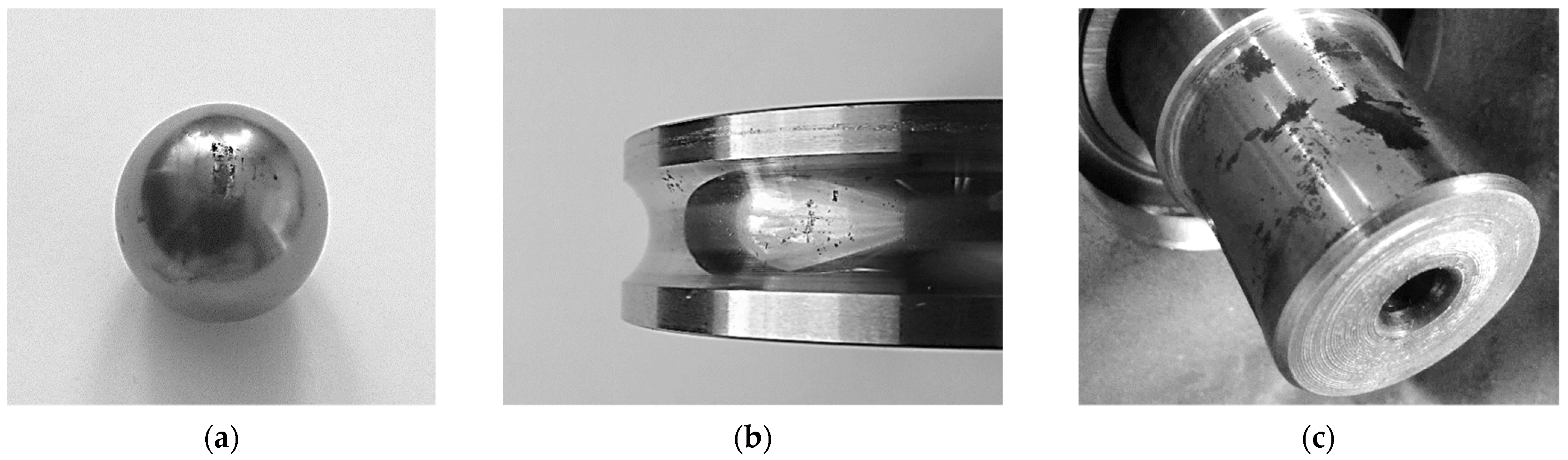
- Bearing damages.
- Shaft breakage or damage to the couplings.
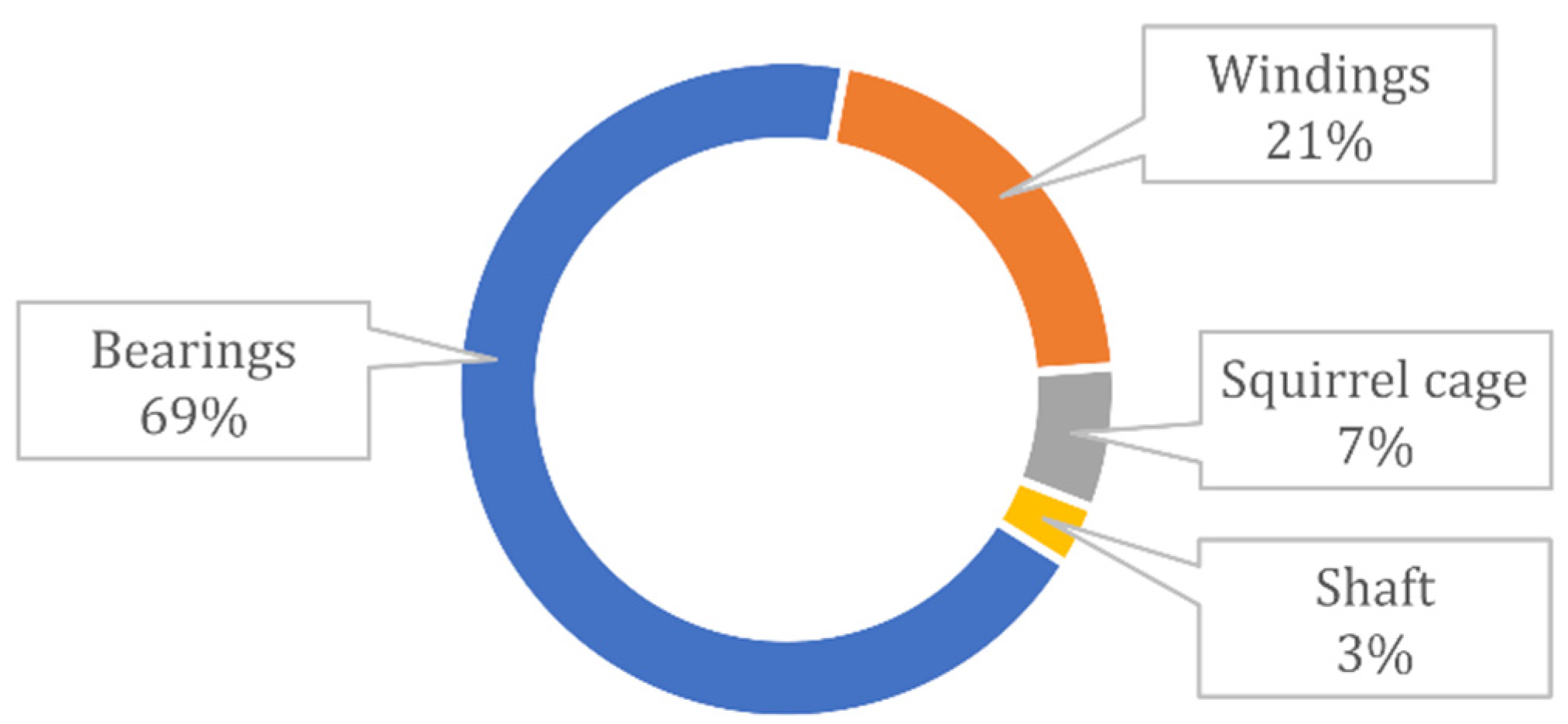
1.1. Causes of Bearing Failures
- Small play in bearings.
- Insufficient lubrication or incorrectly selected lubricant.
- Vibrations resulting from rotor unbalance, excessive play, journal eccentricity, etc.
- Asymmetry in the air gap of the machine contributing to uneven magnetic pull or incorrect centering of the motor and driven machine.
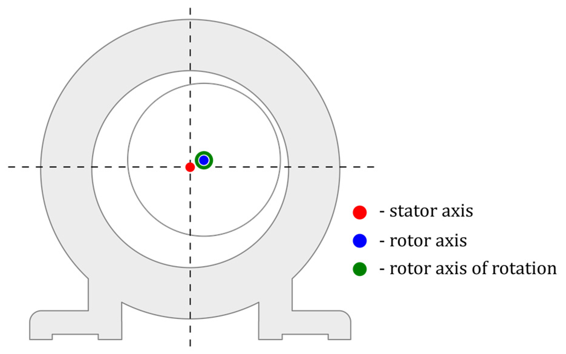
- Rotor eccentricity (circumferential irregularity of the air gap or arc bending of the shaft).
- Asymmetry caused by a short circuit of the stator core or rotor sheets.
- Non-uniformly magnetized permanent magnets placed in the electromagnetic circuit.
- Anisotropy of the sheets forming an electromagnetic circuit.
- Turn-to-turn short-circuits in stator or rotor windings.
- Cracks in the bars or end rings of the rotor cage.
- Differences in the magnetic conductivity of individual segments of the electromagnetic circuit.
- Unbalanced feeding of the machine stator windings.
- Asymmetrical arrangement of ventilation ducts in the electromagnetic circuit.
1.2. Selected Methods of Counteracting Bearing Currents
- Elimination or limitation of the source of the shaft voltage.
- Hindering the flow of the bearing current by increasing the impedance of the path through which the current can flow.
- Controlled flow of the bearing current, limiting the risk of damage to the components of the drive system, in particular the bearings.
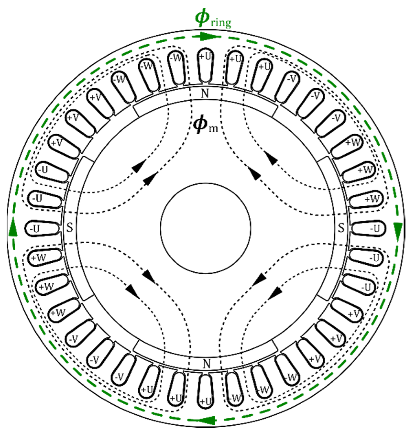
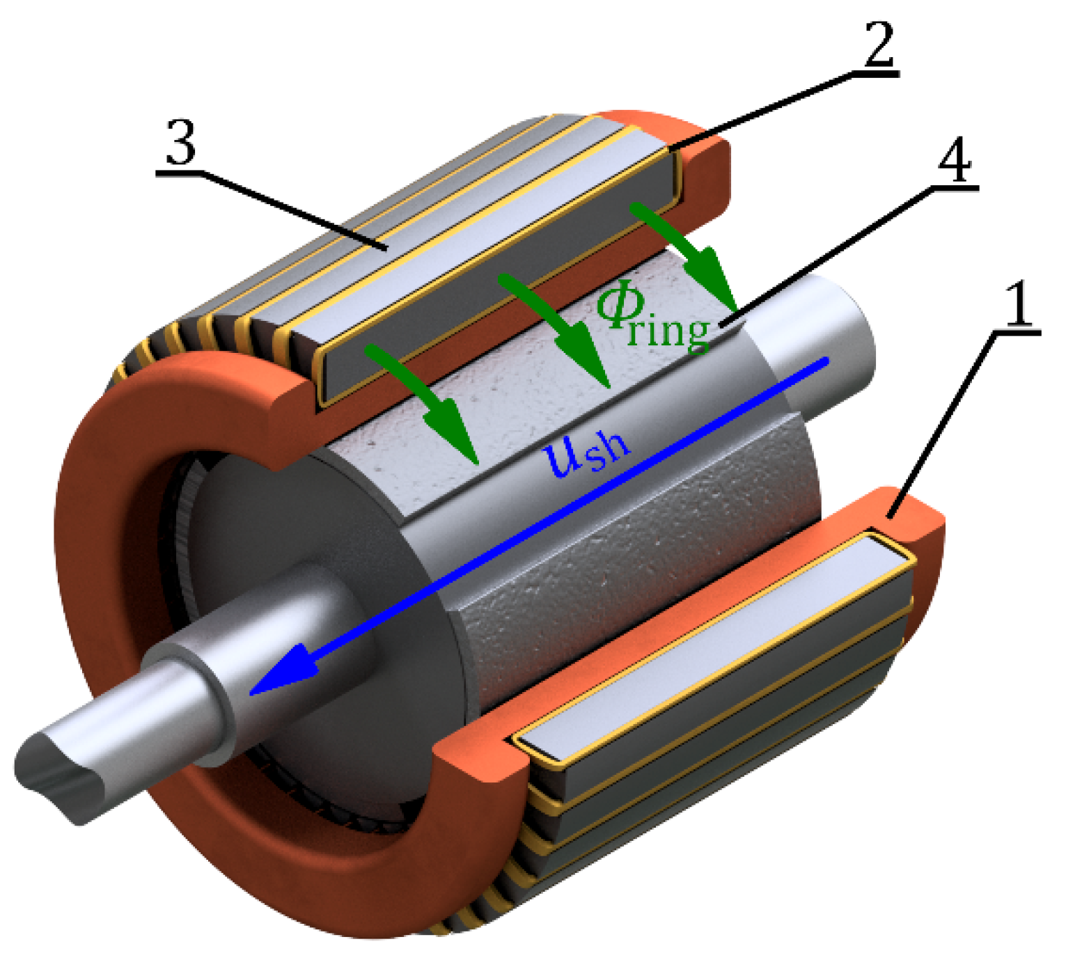
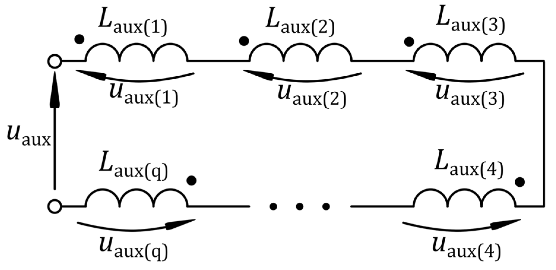
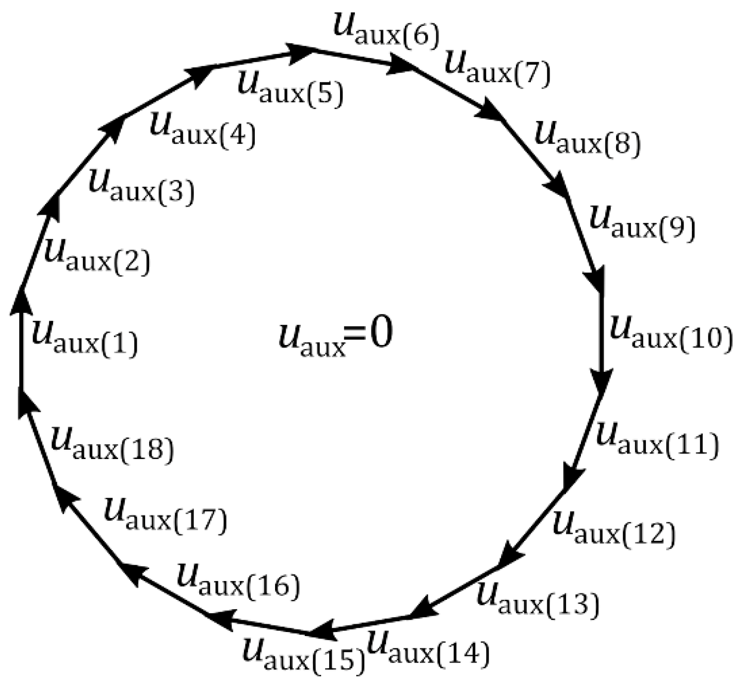
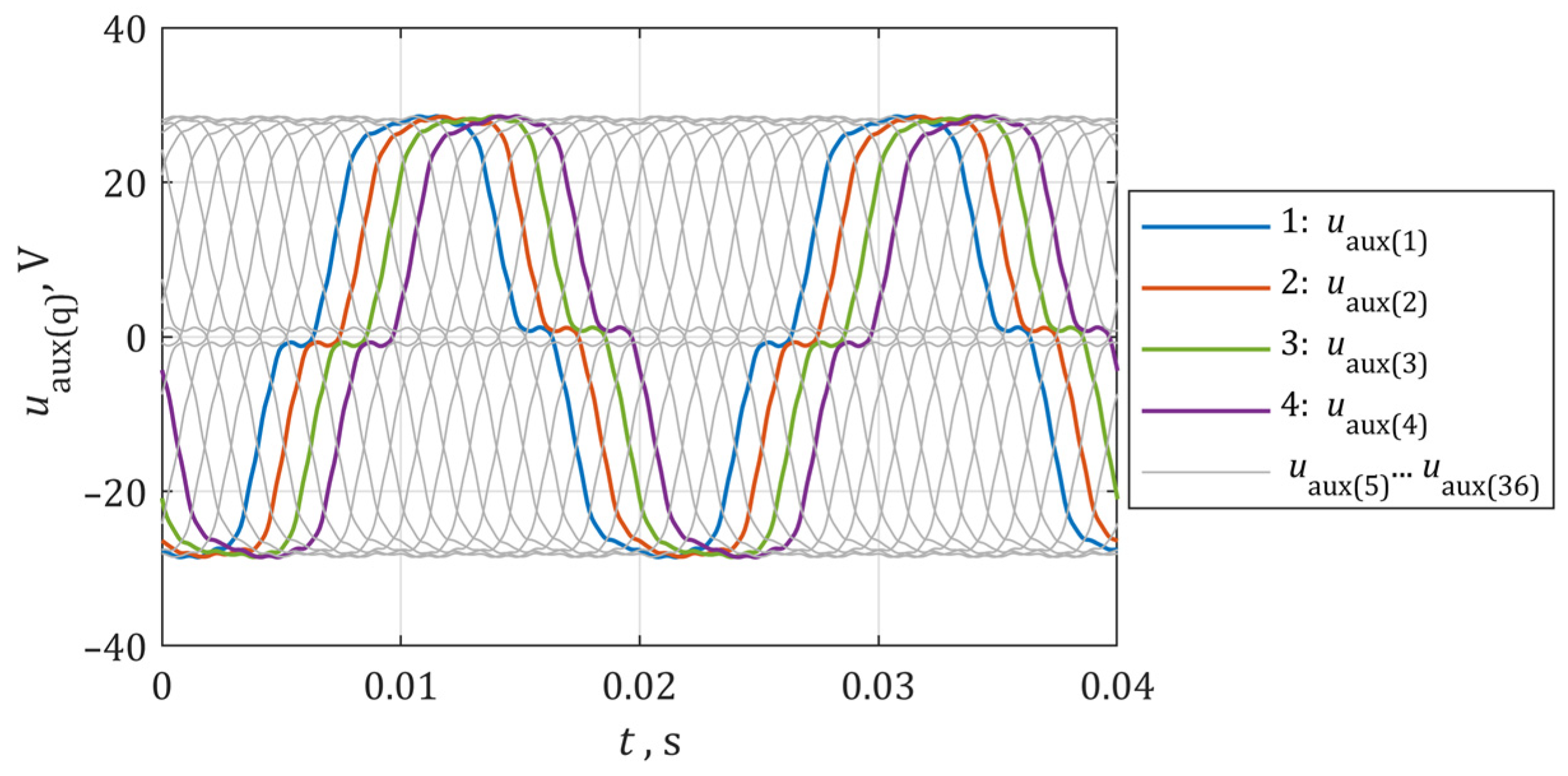
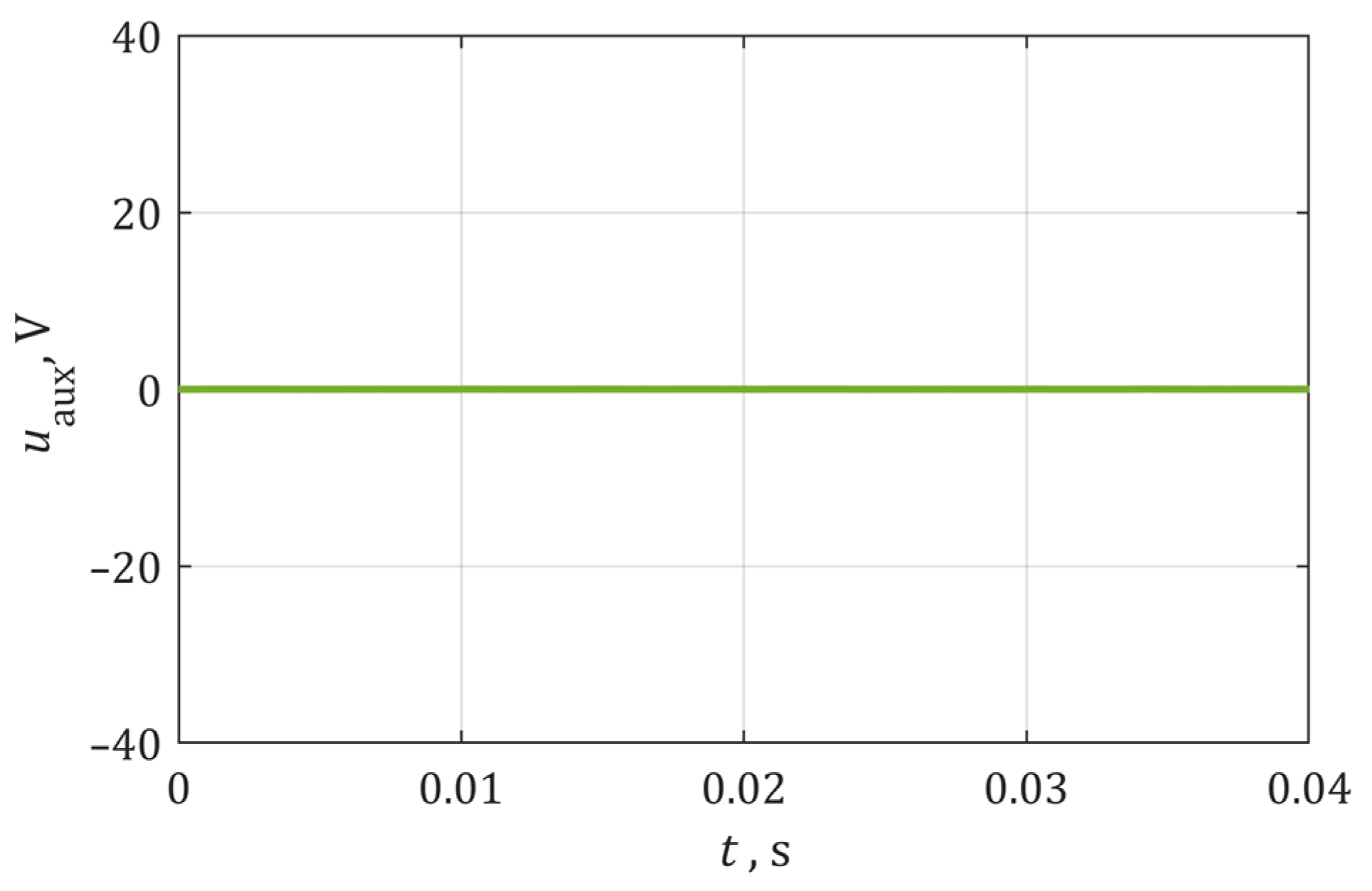
2. The Idea of an Auxiliary Winding in an Electric Machine
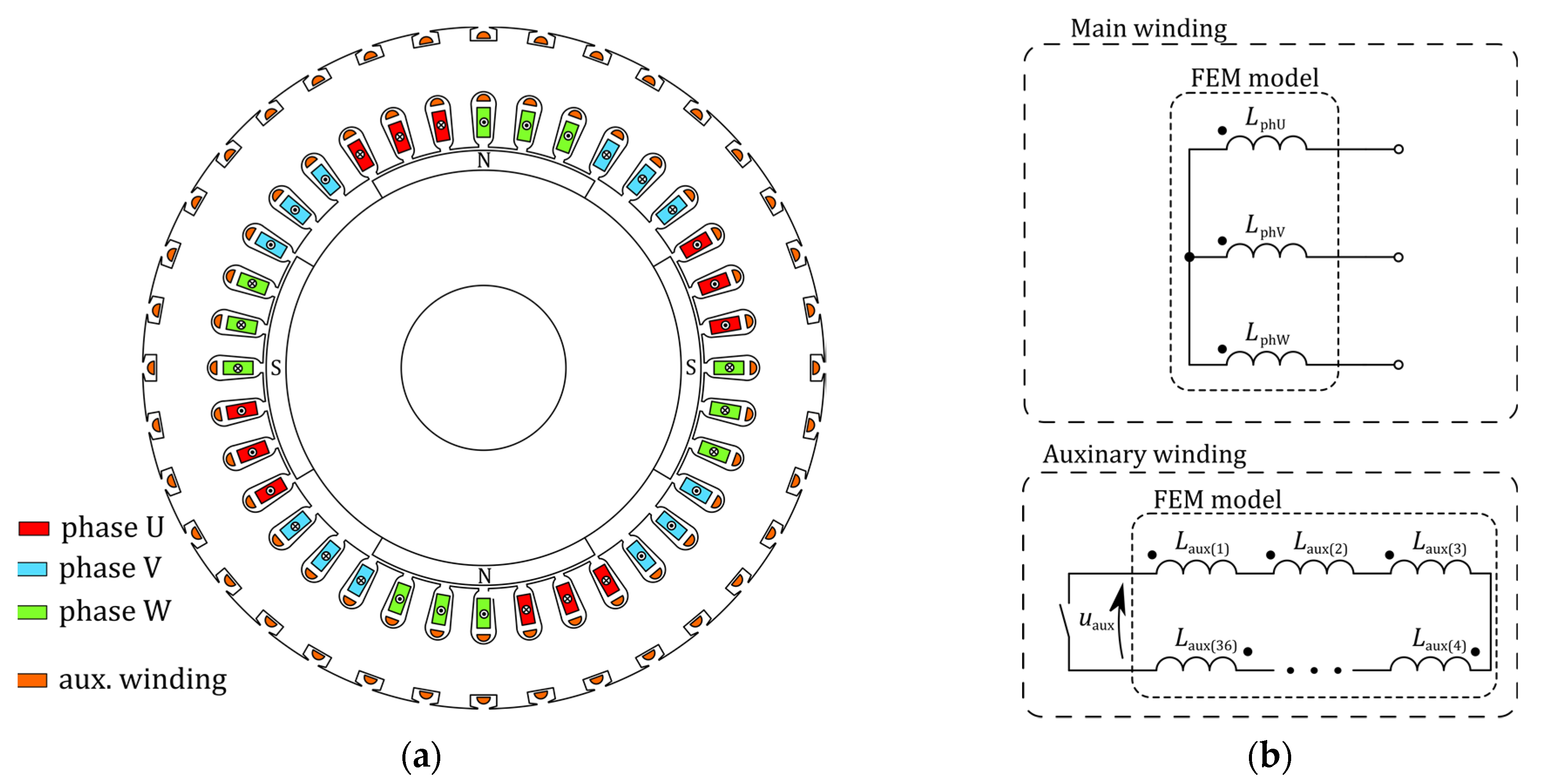
3. Machine Simulation Model and Calculation Results
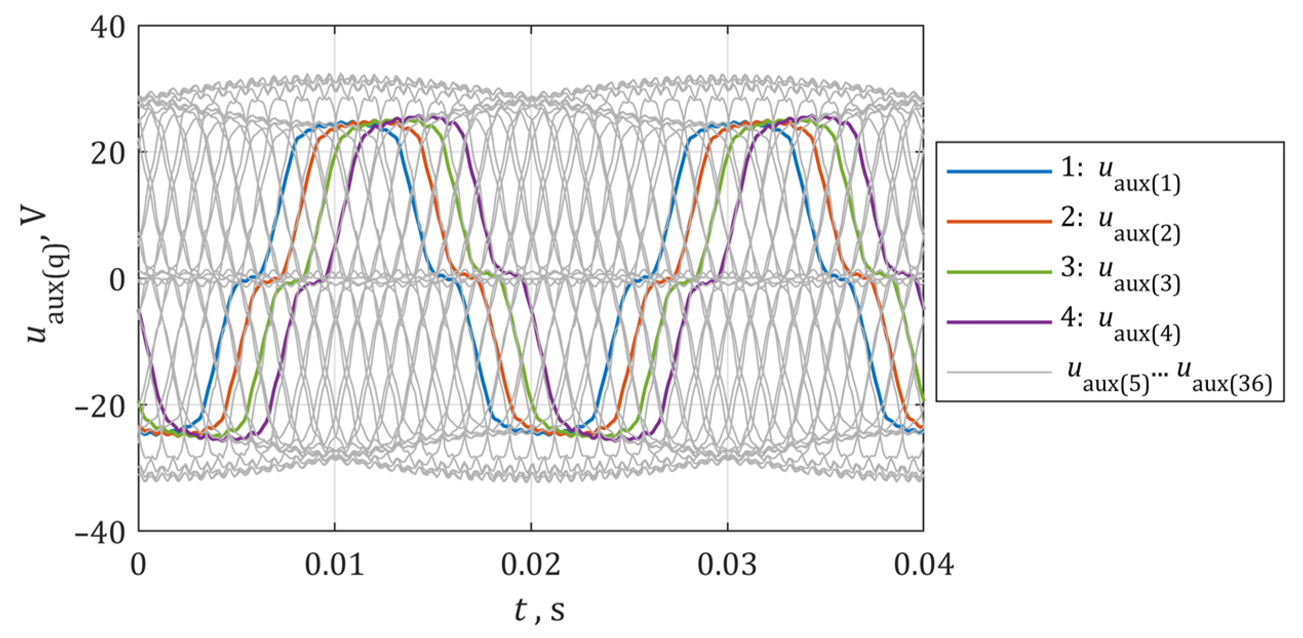
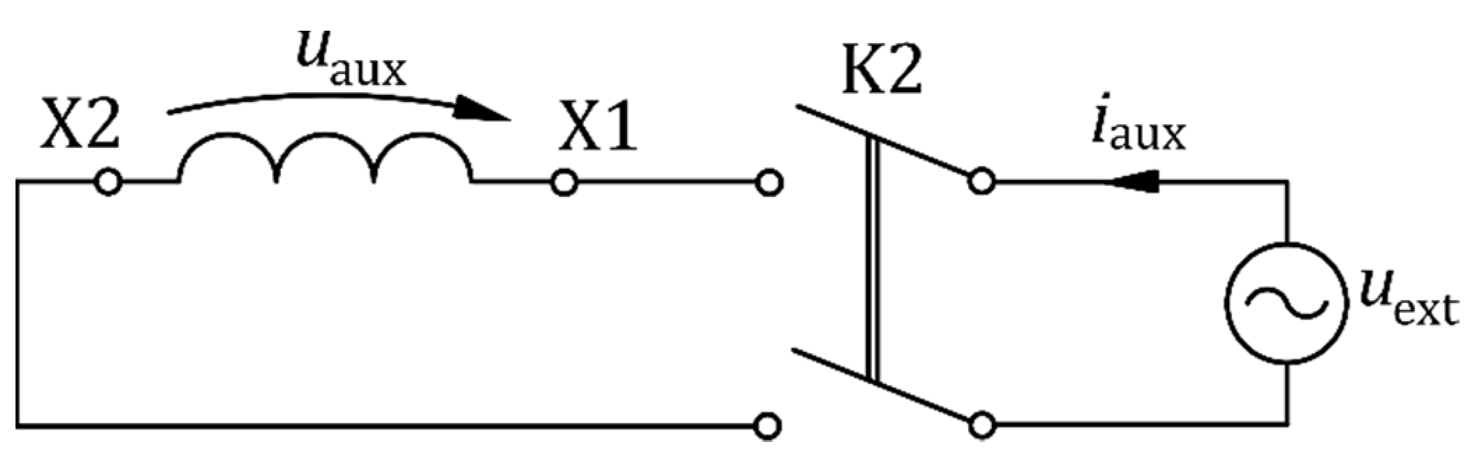
4. Research Model
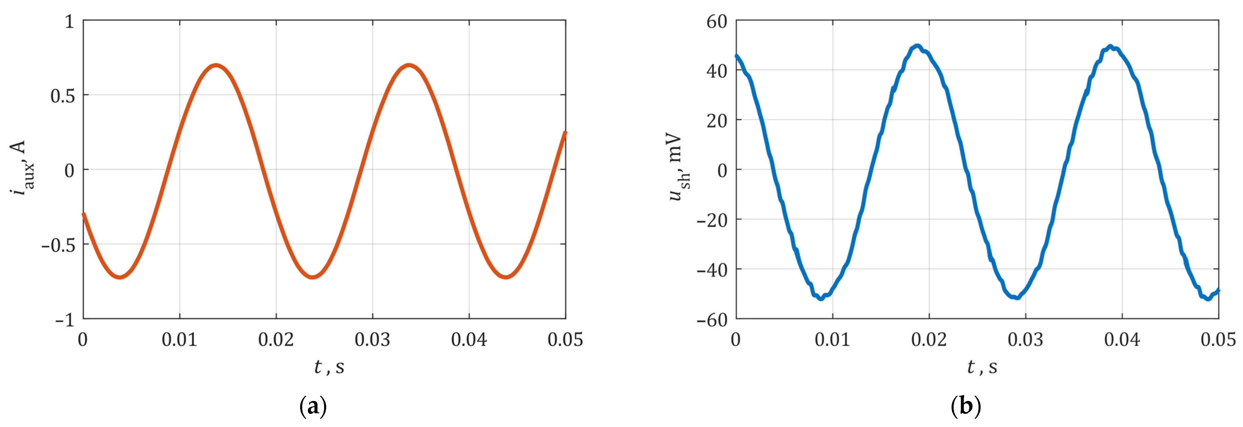
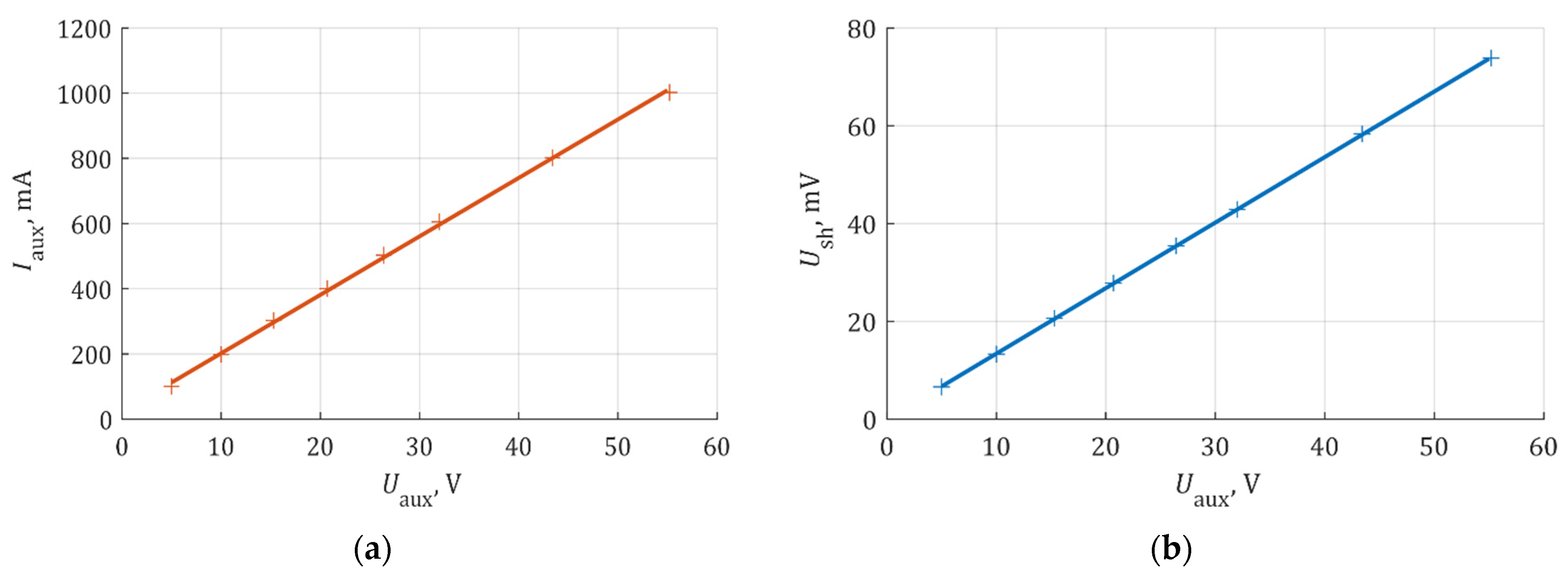
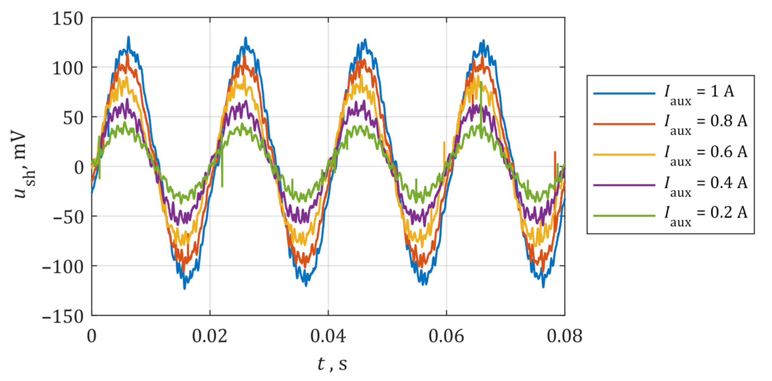
5. Research on a Laboratory Model
6. Conclusions
Author Contributions
Funding
Institutional Review Board Statement
Informed Consent Statement
Data Availability Statement
Conflicts of Interest
References
- Boldea, I. Electric Generators and Motors: An overview. Trans. Electr. Mach. Syst. 2017, 1, 3–14. [Google Scholar] [CrossRef]
- Merizalde, Y.; Hernández-Callejo, L.; Duque-Perez, O. State of the Art and Trends in the Monitoring, Detection and Diagnosis of Failures in Electric Induction Motors. Energies 2017, 10, 1056. [Google Scholar] [CrossRef]
- Pyrhonen, J. Design of Rotating Electrical Machines; Wiley: Chichester, West Sussex, UK; Hoboken, NJ, USA, 2008; ISBN 978-0-470-69516-6. [Google Scholar]
- Baranski, M.; Decner, A.; Polak, A. Selected Diagnostic Methods of Electrical Machines Operating in Industrial Conditions. IEEE Trans. Dielect. Electr. Insul. 2014, 21, 2047–2054. [Google Scholar] [CrossRef]
- Cheng, M.; Sun, L.; Buja, G.; Song, L. Advanced Electrical Machines and Machine-Based Systems for Electric and Hybrid Vehicles. Energies 2015, 8, 9541–9564. [Google Scholar] [CrossRef]
- Pielecha, I.; Cieślik, W.; Szałek, A. Operation of Electric Hybrid Drive Systems in Varied Driving Conditions. Maint. Reliab. 2018, 20, 16–23. [Google Scholar] [CrossRef]
- Lei, G.; Zhu, J.; Guo, Y.; Liu, C.; Ma, B. A Review of Design Optimization Methods for Electrical Machines. Energies 2017, 10, 1962. [Google Scholar] [CrossRef]
- Trigeassou, J.-C. (Ed.) Electrical Machines Diagnosis; ISTE: London, UK, 2011; ISBN 978-1-84821-263-3. [Google Scholar]
- Sun, X.; Zhang, Y.; Lei, G.; Guo, Y.; Zhu, J. An Improved Deadbeat Predictive Stator Flux Control with Reduced-Order Disturbance Observer for In-Wheel PMSMs. IEEE/ASME Trans. Mechatron 2021, 1115–1125. [Google Scholar] [CrossRef]
- Galea, M.; Giangrande, P.; Madonna, V.; Buticchi, G. Reliability-Oriented Design of Electrical Machines: The Design Process for Machines’ Insulation Systems MUST Evolve. IEEE Ind. Electron. Mag. 2020, 14, 20–28. [Google Scholar] [CrossRef]
- Imoru, O.; Jimoh, A.A.; Hamam, Y. Origin and Manifestation of Electrical Machine Faults-A Review. In Proceedings of the 2nd IEEE Conference on Power Engineering and Renewable Energy (ICPERE), Bali, Indonesia, 9–11 December 2014; IEEE: Bali, Indonesia, 2014; pp. 189–194. [Google Scholar]
- Gritli, Y. Diagnosis and Fault Detection in Electrical Machines and Drives Based on Advanced Signal Processing Techniques. Ph.D. Thesis, Università di Bologna, Bologna, Italy, 2014. [Google Scholar]
- Costello, M.J. Shaft Voltages and Rotating Machinery. IEEE Trans. Ind. Appl. 1993, 29, 419–426. [Google Scholar] [CrossRef]
- Sun, X.; Jin, Z.; Chen, L.; Yang, Z. Disturbance Rejection Based on Iterative Learning Control with Extended State Observer for a Four-Degree-of-Freedom Hybrid Magnetic Bearing System. Mech. Syst. Signal Process. 2021, 153, 107465. [Google Scholar] [CrossRef]
- Sun, X.; Jin, Z.; Cai, Y.; Yang, Z.; Chen, L. Grey Wolf Optimization Algorithm Based State Feedback Control for a Bearingless Permanent Magnet Synchronous Machine. IEEE Trans. Power Electron. 2020, 35, 13631–13640. [Google Scholar] [CrossRef]
- SKF. SKF Bearing Maintenance Handbook; SKF: Göteborg, Sweden, 2011; ISBN 978-91-978966-4-1. [Google Scholar]
- Rolling Bearing Damage. Recognition of Damage and Bearing Inspection; Schaeffler Group Industrial: Schweinfurt, Germany, 2001. [Google Scholar]
- Timken Bearing Damage Analysis with Lubrication Reference Guide; The Timken Company: North Canton, OH, USA, 2015.
- Bearing Failure: Causes and Cures; Barden Precision Bearings: Danbury, Connecticut, 1998.
- Bonnett, A.H. Cause and Analysis of Bearing Failures in Electrical Motors. In Proceedings of the [1992] Record of Conference Papers Industry Applications Society 39th Annual Petroleum and Chemical Industry Conference; IEEE: San Antonio, TX, USA, 1992; pp. 87–95. [Google Scholar]
- Upadhyay, R.K.; Kumaraswamidhas, L.A.; Azam, M.S. Rolling Element Bearing Failure Analysis: A Case Study. Case Studies in Engineering Failure Analysis. Elsevier 2013, 1, 15–17. [Google Scholar] [CrossRef]
- Alger, P.L.; Samson, H.W. Shaft Currents in Electric Machines. Trans. Am. Inst. Electr. Eng. 1924, XLIII, 235–245. [Google Scholar] [CrossRef]
- Ong, R.; Dymond, J.H.; Findlay, R.D.; Szabados, B. Shaft Current in AC Induction Machine. An Online Monitoring System and Prediction Rules. IEEE Trans. Ind. Appl. 2001, 37, 1189–1196. [Google Scholar] [CrossRef]
- Plazenet, T.; Boileau, T.; Caironi, C.; Nahid-Mobarakeh, B. An Overview of Shaft Voltages and Bearing Currents in Rotating Machines. In Proceedings of the 2016 IEEE Industry Applications Society Annual Meeting, Portland, OR, USA, 2–6 October 2016; IEEE: Portland, OR, USA, 2016; pp. 1–8. [Google Scholar]
- Chapter 2 Shaft voltages and their origin in rotating machines and flow of electric current through bearings. Tribol. Interface Eng. Ser. 2006, 49, 15–23.
- Motor Shaft Voltages and Bearing Currents under PWM Inverter Operation, Gambica/BEAMA Technical Guide, 3rd ed.; The Gambica Association Ltd.: London, UK, 2016.
- IEEE P1812/D2, January 2013: IEEE Draft Trial-Use Guide for Testing Permanent Magnet Machines; IEEE: New York, NY, USA, 2013; ISBN 978-0-7381-8289-6.
- Bobon, A.; Zientek, P.; Niestroj, R.; Pasko, M.; Kwak, J. The Computational and Measurement Methods of Research on Factors Affecting the Flow of Bearing Currents in High Power Induction Motors. In Proceedings of the 2016 13th Selected Issues of Electrical Engineering and Electronics (WZEE), Rzeszów, Poland, 4–8 May 2016; IEEE: Rzeszów, Poland, 2016; pp. 1–6. [Google Scholar]
- Stone, G.; Lloyd, B.; Sasic, M. Monitoring of Shaft Voltages and Grounding Currents in Rotating Machines. In Proceedings of the 2014 17th International Conference on Electrical Machines and Systems (ICEMS), Hangzhou, China, 22–25 October 2014; IEEE: Hangzhou, China, 2014; pp. 3361–3364. [Google Scholar]
- INSOCOAT Electrically Insulated Rolling Bearings—A Solution for Increased Reliability and Machine Uptime; SKF: Göteborg, Sweden, 2016.
- Sohre, J.S.; Nippes, P.L. Electromagnetic Shaft Currents and Demagnetization on Rotors of Turbines and Compressors. In Proceedings of the 7th Turbomachinery Symposium, College Station, TX, USA, 6–8 December 1978. [Google Scholar] [CrossRef]
- Jarek, T.; Berhausen, S. Analysis of the impact of an auxiliary winding of a permanent magnet synchronous machine on the generation of shaft voltages. In Proceedings of the 2019 15th Selected Issues of Electrical Engineering and Electronics, Zakopane, Poland, 8–10 December 2019; IEEE: Zakopane, Poland, 2019; pp. 1–4. [Google Scholar]


| Parameter | Symbol | Value |
|---|---|---|
| Shaft height | H | 132 mm |
| Number of poles | 2p | 4 |
| Number of stator phases | m | 3 |
| Rated power | SN | 7.2 kV A |
| Rated voltage | UN | 3 × 400 V |
| Rated frequency | fN | 50 Hz |
| Number of stator slots | QS | 36 |
| Rotation Speed n, rpm | Winding Voltage f, Hz | Open Auxiliary Winding | Short-Circuited Auxiliary Winding | ||
|---|---|---|---|---|---|
| Ush, mV | Uaux, V | Ush, mV | Iaux, mA | ||
| 300 | 10 | 3.7 | 1.52 | 2.2 | 123 |
| 600 | 20 | 6.6 | 2.93 | 2.6 | 133 |
| 900 | 30 | 9.6 | 4.45 | 3.7 | 134 |
| 1200 | 40 | 12.1 | 5.88 | 4.4 | 134 |
| 1500 | 50 | 15.0 | 7.38 | 4.6 | 134 |
| Shaft Voltage Ush, mV | Shaft Current Ish, A | |||
|---|---|---|---|---|
| Auxiliary Winding Open | Short-Circuited Aux. Winding | Auxiliary Winding Open | Short-Circuited Aux. Winding | |
| No-load: f = 50 Hz | 15.0 | 4.6 | 2.20 | 0.65 |
| Load: f = 50 Hz, P2 = 3.1 kW I = 4.5 A, cosφ = 0.99 | 16.7 | 5.5 | 1.86 | 0.52 |
| Load: f = 50 Hz, P2 = 2.3 kW I = 4.5 A, cosφ = 0.8 | 17.8 | 6.0 | 2.00 | 0.40 |
Publisher’s Note: MDPI stays neutral with regard to jurisdictional claims in published maps and institutional affiliations. |
© 2021 by the authors. Licensee MDPI, Basel, Switzerland. This article is an open access article distributed under the terms and conditions of the Creative Commons Attribution (CC BY) license (https://creativecommons.org/licenses/by/4.0/).
Share and Cite
Berhausen, S.; Jarek, T. Method of Limiting Shaft Voltages in AC Electric Machines. Energies 2021, 14, 3326. https://doi.org/10.3390/en14113326
Berhausen S, Jarek T. Method of Limiting Shaft Voltages in AC Electric Machines. Energies. 2021; 14(11):3326. https://doi.org/10.3390/en14113326
Chicago/Turabian StyleBerhausen, Sebastian, and Tomasz Jarek. 2021. "Method of Limiting Shaft Voltages in AC Electric Machines" Energies 14, no. 11: 3326. https://doi.org/10.3390/en14113326
APA StyleBerhausen, S., & Jarek, T. (2021). Method of Limiting Shaft Voltages in AC Electric Machines. Energies, 14(11), 3326. https://doi.org/10.3390/en14113326