Article

Experimental and CFD Investigation on the Application for Aerogel Insulation in Buildings

by
Santu Golder
1,
Ramadas Narayanan
2,*,
Md. Rashed Hossain
1 and
Mohammad Rofiqul Islam
1
1
Department of Mechanical Engineering, Rajshahi University of Engineering & Technology, Rajshahi 6204, Bangladesh
2
Centre for Intelligent Systems, School of Engineering and Technology, Central Queensland University, 6 University Drive, Bundaberg, QLD 4670, Australia
*
Author to whom correspondence should be addressed.
Energies 2021, 14(11), 3310; https://doi.org/10.3390/en14113310
Submission received: 12 April 2021 / Revised: 19 May 2021 / Accepted: 26 May 2021 / Published: 4 June 2021
(This article belongs to the Special Issue Advanced Buildings Thermal Monitoring)

Abstract

:
Reducing building energy consumption is a significant challenge and is one of the most important research areas worldwide. Insulation will help to keep the building’s desired temperature by reducing the heat flow. Additionally, proper insulation can provide an extended period of comfort, leading to reduced building energy requirements. Encapsulated air is the major aspect of most thermal insulation materials. Low thermal conductivity is a good characteristic of thermal insulation materials. Aerogel has low thermal conductivity, so it is suitable for glazing and insulation purposes. This research paper investigates the effectiveness of aerogel as an insulation material in buildings by incorporating a translucent aerogel-glazing system in the window and aerogel insulation in the wall of a building. Experimental investigation of a 10 mm thick aerogel blanket surrounded box was conducted to assess its performance. Additionally, a CFD simulation was conducted, and the results of temperature degradation for the wall showed good agreement with experimental results. Additionally, the CFD simulation of temperature decay was compared between the aerogel-glazed window and argon-glazed window. It was found that the aerogel-glazed window has slower temperature decay compared to the argon-glazed window. The results showed that integrating aerogel in the glazing system and wall insulation in a building has the potential to reduce the building’s energy consumption. Moreover, a numeric simulation was conducted, and showed that the building’s annual energy consumption is reduced by 6% with the use of aerogel insulation compared to fiberglass.

1. Introduction

Energy saving in the building is an important issue globally as building energy consumption is increasing rapidly because of increased demand for indoor comfort. Greenhouse gas emission from the building sector is now more significant than ever [1,2,3,4,5,6,7]. Additionally, immediate energy conservation is needed worldwide because of the short supply of fossil fuel, inadequate availability of fossil fuel, and rising energy costs. This study is focused on the development of an aerogel insulation system for reducing building energy consumption.
Thermal insulation is the potential way to reduce energy in a cold and hot climate where energy is highly used for heating and cooling. The insulation materials are needed to improve comfort level, reduce energy consumption, and increase the building’s life. Thermal characteristics of insulation materials, mainly thermal conductivity and specific heat, are the significant heat transfer factors that depend on the wall’s materials, convection, and radiation characteristics. Low thermal conductivity (W m−1 K−1) enables the application of a thin building envelope with low thermal transmittance (W m−2 K−1) [8].
The traditional envelopes used are mineral wool, expanded polystyrene, extruded polystyrene, cellulose, cork, and polyurethane. Now, the Vacuum Insulation Panel (VIP) is more and more used for building wall and roof applications. The VIP consists of an open, permeable core-fumed silica sealed in a high-quality barrier laminate bag. It is the only insulation material with thermal conductivity ranging from 3 to 4 m W m−1 K−1 at the center of the VIP panel [8]. For building applications, the value of thermal conductivity for VIP panels is typically 7 m W m−1 K−1 considering the edge effect and typical aging [9]. Moreover, higher thickness (10 mm, 20 mm, 30 mm) insulation material is used in traditional insulation systems for the best thermal insulation in the building envelope. However, very thick building envelopes cost space, money, floor area, architectural restrictions, and building techniques [8].
Conversely, aerogel is a dried gel with high porosity and lower thermal conductivity than air [10]. Aerogel was first discovered in 1930; silica aerogel, aerogel monoliths, cabot aerogel, and various products were developed afterwards using aerogel. Silica is the main raw material of aerogel. It is non-toxic, low-flammable, air-permeable, and lightweight [11]. Aerogels are also used in batteries, nuclear waste storage, absorbents, and shock absorbers [11]. Aerogel is now a promising new insulation material for building applications because of its low thermal conductivity.
Aerogel has a thermal conductivity range of 0.01–0.02 W m−1 K−1 at ambient temperature [12]. The value 0.01 W m−1 K−1 corresponds to the vacuum condition, resulting in a well-balanced connection among low solid skeleton conductivity, low gaseous conductivity, and low radiative infrared transmission. The value of 0.02 W m−1 K−1 corresponds to atmospheric conditions. Additionally, it has a very good optical property for application in building fenestration systems [12,13].
There are many types of research projects conducted in the past exploring the characteristics and use of aerogel. Jelle [8] worked on thermal conductivity and emissivity of aerogel and concluded that there are no materials or solutions that can satisfy all the requirements for a building’s insulation and glazing system. Berardi [12] performed daylight analysis for a monolithic-aerogel-glazed window. A lighting assessment determined the percentage of time in which the level of daylight illuminance was useful and sufficient for the occupants. A window filled with 40% aerogel is a potential option for retrofitting a building.
Experimental analysis for the thermal performance of aerogel-insulating material was developed and presented by Lucci et al. [14]. According to Lucci et al. [14], aerogel insulation is a promising insulation material for assembling the historic building.
Cuce et al. [15] investigated the optimum thickness for aerogel insulation and the environmental effects for the Nottingham, UK climate condition. Aerogel-insulated apartments provide slimmer walls with a larger living area in the room compared to conventional apartments. Aerogel insulation is very suitable for the non-insulated hollow wall.
The energy performance of a building made with aerogel insulation, conventional insulation, without insulation, and double-glazed insulation was evaluated by Mujeeb et al. [16]. Replacing the double-glazed window with a nanogel-glazed window achieves energy-saving up to 14%. Conversely, polystyrene foam with nano VIP walls and roof saves 0.5% and 0.8% energy consumption of a building accordingly.
Li et al. [17] investigated the performance of windows that are combined with aerogel, glass, and phase change elements. The integration of aerogel insulation in the PCM (phase-change material) glass window is worthy technology. This technique solves the application of PCM technology in windows effectively by exploiting the window latent heat in the cold climate condition in China.
Yang et al. [18] experimented with eight glazing samples for the window with two different thicknesses (5 mm, 7.5 mm). Results showed that installing aerogel glazing at the outside of the window in skylights is more effective. Heat gain for the envelope was also decreased by 31% by replacing single glazing.
Windows are the weakest point in the building through which heat and energy can easily transfer. Poor thermal performance of windows is largely being attributed to higher thermal transmittance than glazing parts. Filling the existing empty cavities in window frames with aerogel granular can decrease the frame-thermal transmittance to 4–29%. Moreover, a complete filling of the cavity with aerogel can reduce thermal transmittance to 35%, and thermal transmittance becomes 0.5 W m−2 K−1 [19,20]. Jason et al. [20] should have compared this with a frame filled with conventional insulation.
Leung et al. [21] analyzed nine aerogel glazing systems for evaluating the optical properties and thermal performance for the window. Aerogel glazing can bring up to 57% reduction in heat gains for windows, and it also reduces 8.5% cooling energy consumption of the building.
The thermal performance of a window made with polyvinyl chloride (PVC) frame was experimented with aerogel granules in the cavities. With this, thermal transmittance can be decreased by 30% [21]. Thermal transmittance of the frame can be reduced to 0.8 W m−2 K−1 by filling the cavity with aerogel granules [22]. A greenhouse gas emission comparison for the room with the argon-glazed window and aerogel-glazed window was compared by Nicola et al. [23]. They found that a 5–10% reduction in emission can be achieved by using an aerogel-glazing system.
Aerogel ceramics are also very attractive thermal insulation materials due to the lightweight and low thermal conductivity. An et al. manufactured ceramic aerogel composites where fiber with silica aerogel promises insulation with thermal conductivity at 0.0253 W m−1 K−1 and a density of 0.1 g cm−3 [24]. An et al. developed aerogel insulation material with a thermal conductivity and density of 0.0224 W m−1 K−1, 0.05 g cm−3, respectively [25]. Ruizhe et al. also developed hierarchical insulation ceramic material that has a thermal conductivity of 0.035 W m−1 K−1 and 89.85 MPa compressive strength [26].
Silica aerogel is thermally insulated material that can give advantages in building thermal insulation. Good acoustic insulation was obtained by considering 12.7 mm thick aerogel insulation, and the absorption coefficient can be obtained as 0.88 at 1500 Hz [27]. The significant improvement of noise insulation can be achieved by using an aerogel-glazing system.
However, the combined effect of incorporating aerogel in walls and windows is not investigated adequately. In this paper, a comprehensive CFD model was developed to represent a room with aerogel insulation. This model is validated by conducting an experimental investigation and comparing the experimental results with the model. Then, the validated model is used for further investigation to compare the performance of aerogel insulation with other existing insulation materials. The CFD simulation was limited to a room insulated with aerogel. With the same parameters, the whole building simulation was carried out using the EnergyPlus model, which predicated the annual energy saving for a typical building with aerogel insulation.

2. Properties of Aerogel

Aerogel is a lightweight solid derived from gel in which the liquid component of the gel has been replaced with air and makes aerogel extremely low density with low thermal conductivity. Because of these unique properties, aerogel is considered one of the most efficient insulating materials [28,29]. Space is occupied with air unless it is sealed under a vacuum in aerogel. Because of the transparent property of silica aerogel, it is applicable in windows and skylights. At a low temperature, radiation is not a significant problem for transparent material. However, at a high temperature, radiative transport is dominant for thermal conduction.
A commercially available, space loft aerogel blanket has a heat capacity of 1000 J kg−1 K−1, vapor permeability factor 4.7 Mu, porosity 91%, and water absorption coefficient 0.025 kg m−2h−1/2 [30,31]. The space loft aerogel blanket is called fiber-reinforced silica aerogel. It is suitable for insulating solid walls, floors, and roofs and is associated with recent and old buildings. Space loft reduces the surface condensation and provides a highly effective technique for heat loss reduction through floors and walls. Space loft is produced in a roll of 5 or 10 mm thick, 1.45 m wide, and around 65 m2 roll−1. Additionally, it does not depend on a vacuum or gases for insulation [31]. For simulation, the properties considered for space loft aerogel and glass are shown in Table 1. Thermal properties of wood, argon, and air are embedded in ANSYS FLUENT [32]. According to Saffa et al. [33], thermal conductivity and density of aerogel are in the range of 0.01–0.02 W m−1 K−1 and 3–350 kg m−3 accordingly. Additionally, 0.014 W m−1 K−1 thermal conductivity and 3 kg m−3 density of aerogel at room temperature were found by Saffa et al. [33]. According to Baetens et al. [13], 0.013 W m−1 K−1 thermal conductivity of aerogel is commercially available. At room temperature, aerogel has a thermal conductivity of 0.013 W m−1 K−1 [34]. According to Omer et al. [35], aerogel has 0.013 W m−1 K−1 thermal conductivity and 3 kg m−3 density.
For the application of aerogel in the building as a glazing system and room insulation, it is necessary to investigate the following information:
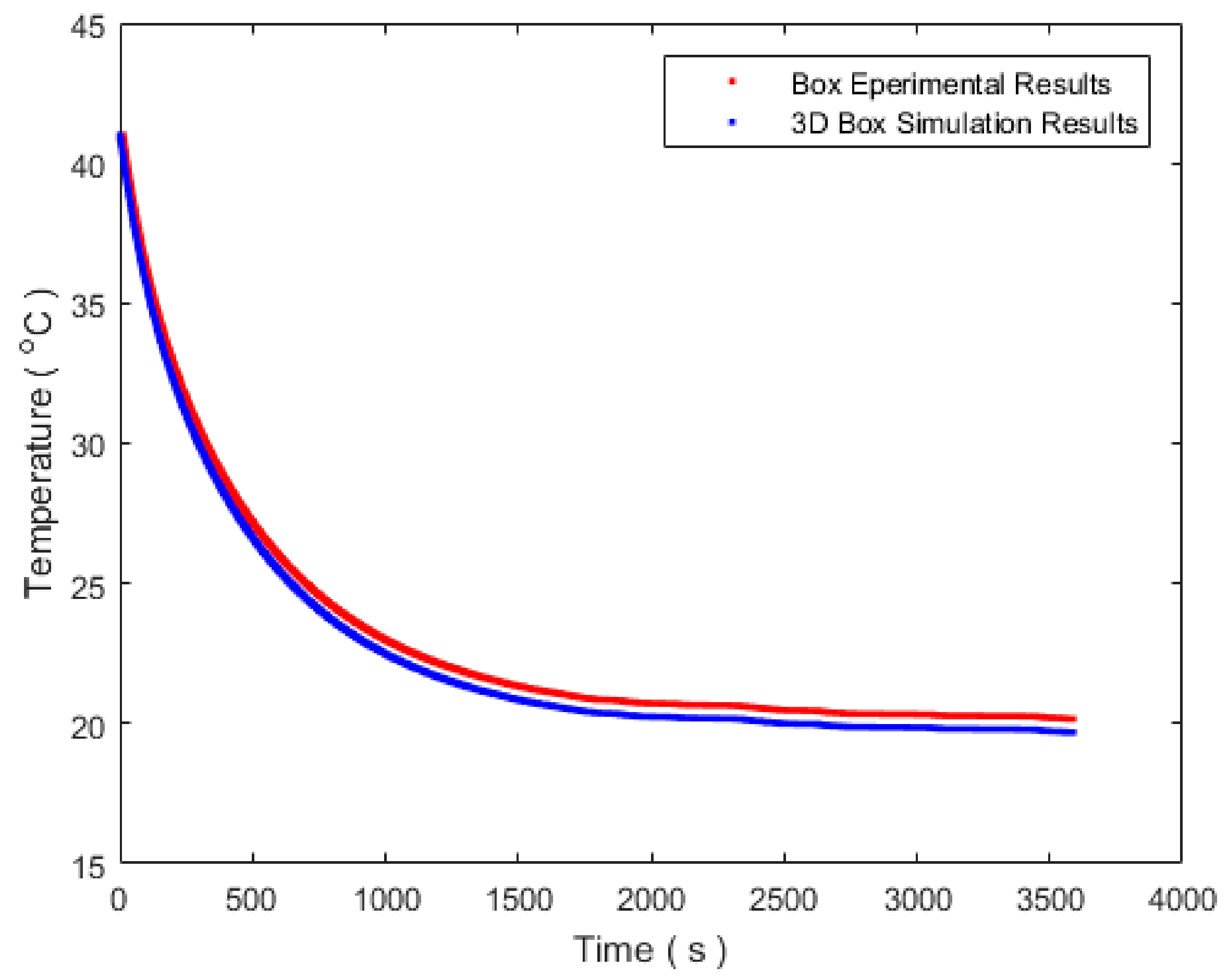
  • Temperature deterioration of the inside wall of an aerogel-surrounded box.
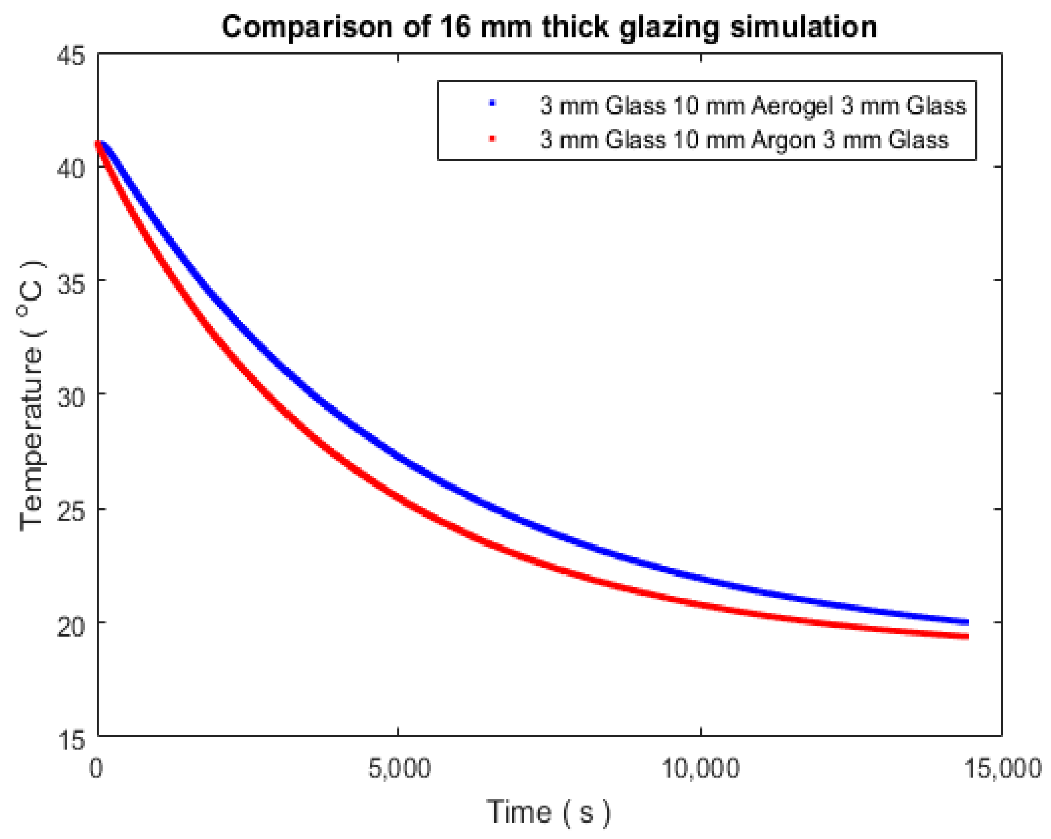
  • Temperature decay of the inside wall of an aerogel-glazed window.
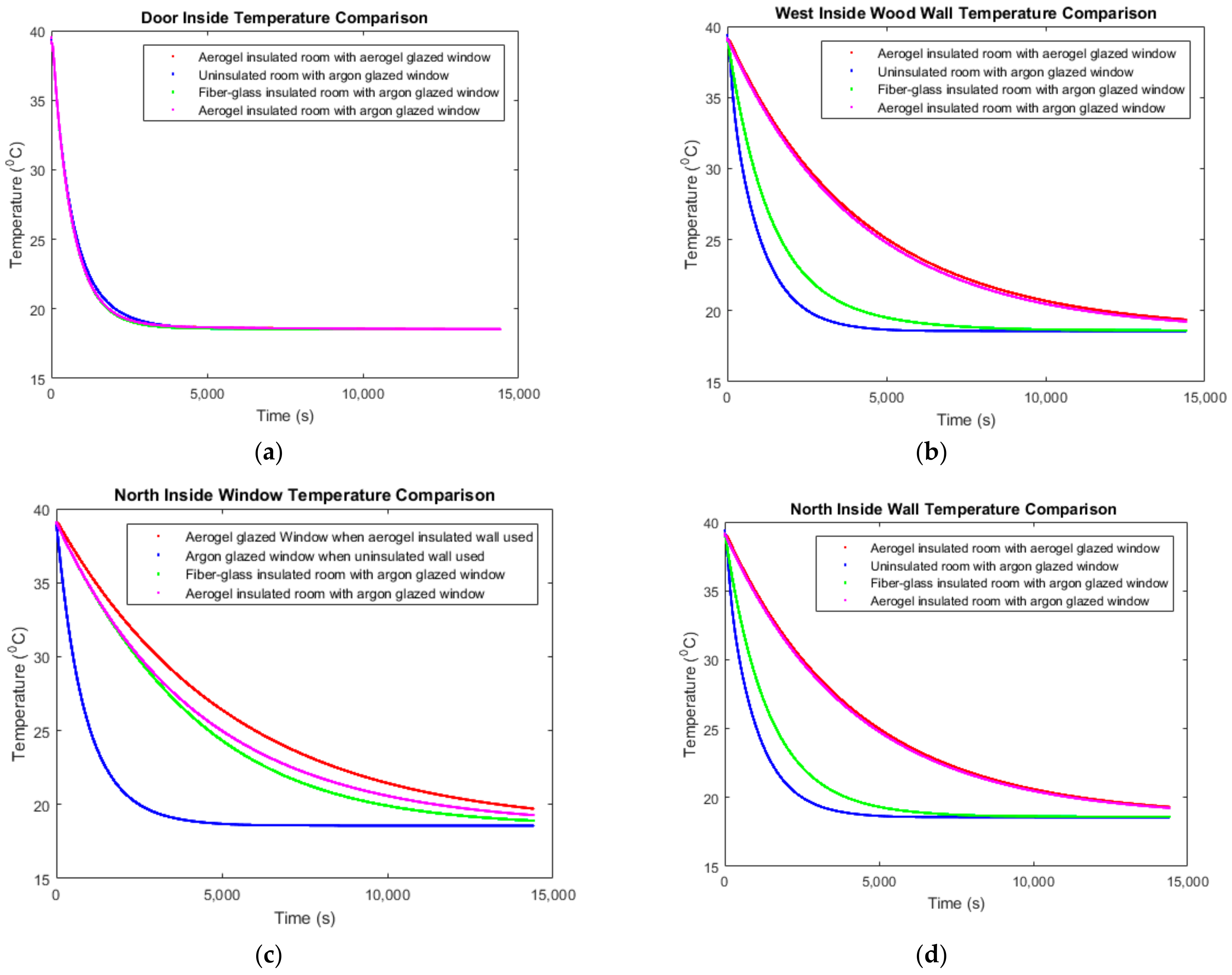
  • Temperature degradation of the aerogel-insulated wall with an aerogel-glazed room.
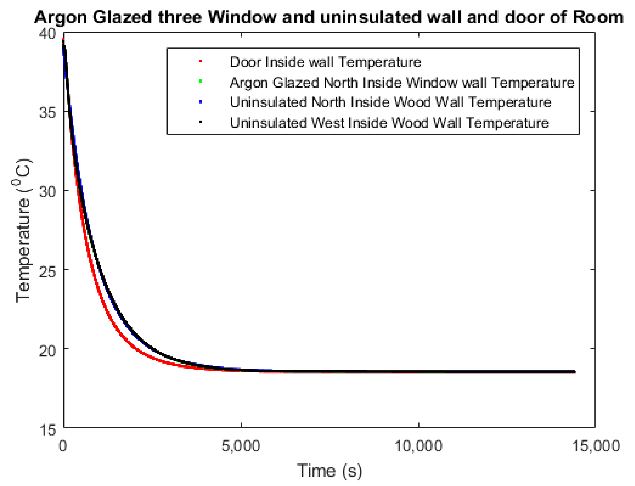
  • Comparison between temperature deterioration of the aerogel insulated with aerogel-glazed room and argon-glazed with fiberglass-insulated room.
  • Comparison of building energy consumption between aerogel- and fiberglass-insulated room.
The optical and thermal properties are important for glazing. The transmittance of the aerogel-glazing system ranged from 0.058 to 0.491. However, aerogel-glazing can reduce cooling energy consumption because of its low solar heat gain coefficient (SHGC). There is also a correlation between transmittance and SHGC. SHGC is increased with the increase of transmittance [21]. Table 2 presents the optical and thermal properties of aerogel glazing system.

3. Model Development

3.1. CFD Model

In order to investigate the performance of space loft aerogel as an insulation material in a building (wall, window, and door), the Computational Fluid Dynamic tool, ANSYS FLUENT, was selected. The Navier–Stokes Equation forms the governing equations.
Two-dimensional energy equations are the governing equations of the model [42]:
T t + U T X + V T Y = k 2 T X 2 + 2 T Y 2
The Navier–Stokes equation with the Boussinesq approximation that is used in ANSYS FLUENT is shown by the Equations (2)–(4), respectively [42].
U x + V y = 0
U t + U U x + V U y = 1 ρ P x + ν 2 U x 2 + 2 U y 2
V t + U V x + V V y = 1 ρ P y + ν 2 V x 2 + 2 V y 2 + g β ( T T 0 )

3.2. Auxiliary Equations for Radiation

In the simulation, the surface-to-surface radiation model (S2S) is considered. The S2S radiation model is used to calculate the radiation transfer of an enclosed grey surface. Size, orientation, and separated distance are the main factors for energy exchange among surfaces. According to the ANSYS user guide [32], the surface-to-surface (S2S) model is applicable for opaque surfaces. In the room, most of the surface is made of wood. Wood is opaque, and this S2S model is suitable for the room simulation. For the surface-to-surface radiation, the following mathematical equation is used for the energy that is reflected from k surface [32]:
q out , k = k σ T k 4 + ρ k q in , k
Incident energy from one surface to another surface is directly connected with the surface-to-surface view factor F jk . View factor is defined as the amount of energy leaving from surface k that is an incident on j surface. Energy flux ( q in , k ) can be defined for the energy leaving from all of the surfaces as follows:
A k q in , k = j = 1 N A j q out , j F jk
Here, A k = Surface area of k. For N number of surfaces, the view factor relationship is given below:
A j F jk = A k F kj   for   j = 1 , 2 , 3 , , N
q in , k = j = 1 N F kj q out , j
Therefore, the surface-to-surface radiation model can be written as follows:
q out , k = k σ T k 4 + ρ k j = 1 N F kj q out , j

3.3. Model Details and Boundary Conditions

For Computation Fluid Dynamics (CFD) modelling, a 3D box with length × width × height of 1 m × 1 m × 1 m covered with an aerogel blanket is made in ANSYS FLUENT 2020 R1 [32]. The computational domain is defined as the air in the box inside, and the box wall is modelled with a 10 mm thick aerogel blanket. A mesh independent analysis was performed in the simulation. In the simulation, more than 3 million elements (3,166,951) were considered for better results. The simulation was considered as a transient model with a time-step size and residual convergence criteria of 0.005 (s) and 10−6, respectively. Additionally, maximum iteration per time step was defined as 20, and gravity was defined as 9.81 m/s2 in the negative “y” direction.
The following computational fluid dynamic models are considered for the simulation:
  • The laminar flow model is considered.
  • The energy equation is used in the simulation.
  • The surface-to-surface (S2S) radiation model is also considered in the simulation.
The boundary conditions are described as follows:
The outside temperature of the aerogel blanket surrounded box and the glazed box were considered as 291.5 K, and the inside temperature was 314 K, as these temperatures were recorded in the experiment.
A box with a 10 mm thick aerogel layer was considered as a prototype of a living room. Six sides of the box were surrounded by an aerogel blanket, as shown in Figure 1. A heater was used at the center of the box to raise the temperature to 41.85 °C (314 K). The heater was stopped when the inside wall temperature reached 41.85 °C (314 K), and the outside temperature of the box was 18.33 °C (291.5 K). After reaching the temperature of 41.85 °C (314 K) of the inside wall, temperature degradation was monitored and recorded. Figure 2 is the schematic drawing of a room with three windows and a door that is considered for the simulation.

4. Results and Discussion

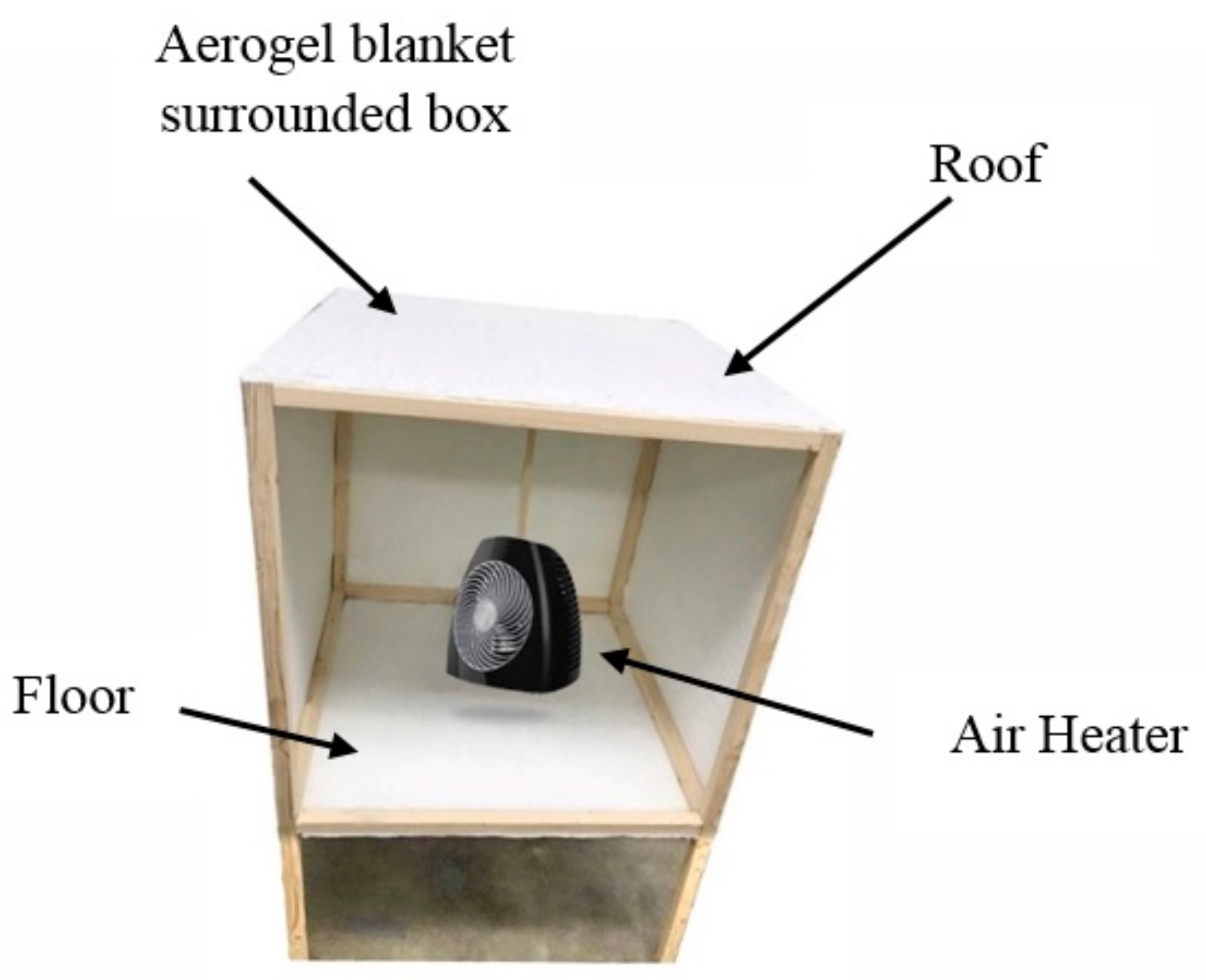
4.1. Experiment and Simulation Results for the Aerogel Blanket Surrounded Box

In the experiment, six sensors were installed on the interior side of an aerogel blanket-covered box. Every sensor recorded temperature decay (°C) at its side. The inside and outside wall temperatures were defined as 41.85 °C (314 K) and 18.33 °C (291.5 K), respectively, in the aerogel blanket-covered box. Afterwards, simulation runs were conducted, and the temperature decay in the simulated wall was observed (based on an interval of 0.005 s for a total time of one hour). In the simulation, the “solar ray tracing model” was not considered because the temperature decay experiment for the aerogel surrounded box has to be experimented in a laboratory room where electric light and air conditioning systems were present. Simulation results compared fairly well with experimental results, as shown in Figure 3. It is assumed here that the roof and floor of the room are also insulated with an aerogel blanket, as shown in Figure 1. The temperature deterioration of the roof and floor are also similar to Figure 3.
Subsequently, two types of simulations were conducted to find the effect of glass wall thickness on reducing building energy consumption. In the 1 m3 size of the box, a 10 mm thickness of glazing was considered in between two 3 mm thickness of glass walls and two 4 mm thickness of glass walls. The temperature decay comparison shows that thicker glass with the same glazing system reduces more energy, as shown by Figure 4a. The solar ray-tracing model for the −5 GMT zone was also considered for the 1 m3 box, considering a 10 mm thick aerogel layer at the middle of the 4 mm and 3 mm thick glass layer. The starting time of simulation was defined from 13 h on 21 June, where longitude and latitude were −84.63° and 13.65°, respectively. Simulations were conducted for 10,800 s (3 h). It is found from Figure 4b that the 4 mm thick glass with a 10 mm thick aerogel glazing system reduces more energy compared to the 3 mm thick glass with a 10 mm aerogel-glazing system. Figure 5 shows that a glass-aerogel-glass-glazed window reduces more energy compared to the glass-argon-glass-glazed window. The simulation for aerogel- and argon-glazed windows were considered for 4 h (14,400 s).
The glass-aerogel-glass-glazing system showed better results compared to glass-argon-glass. Additionally, glass-aerogel-glass-glazed windows allowed less energy to dissipate compared to other glazed windows.

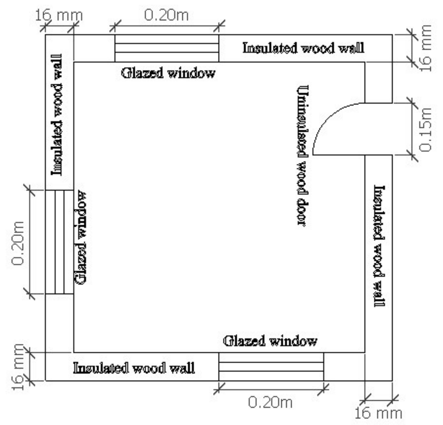
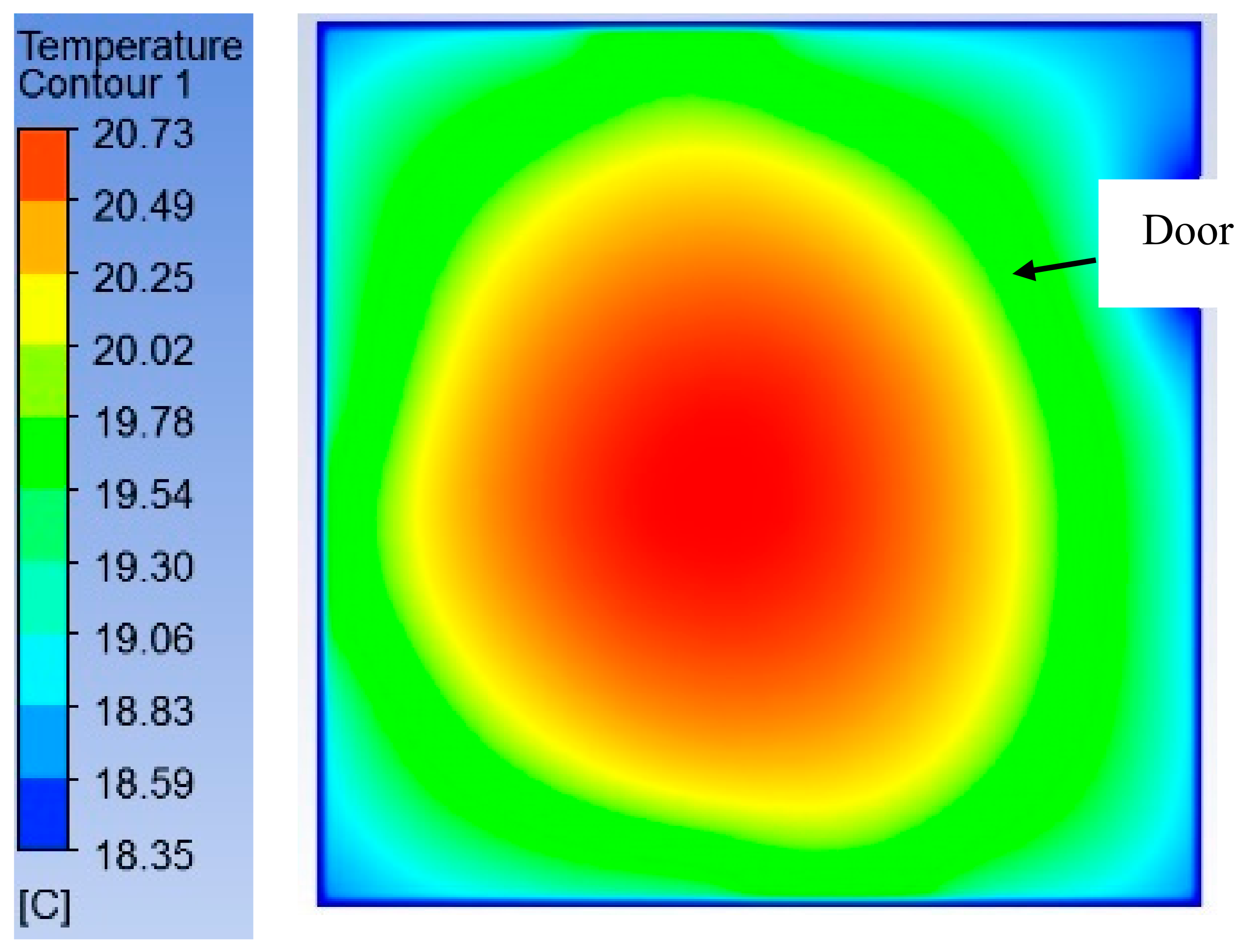
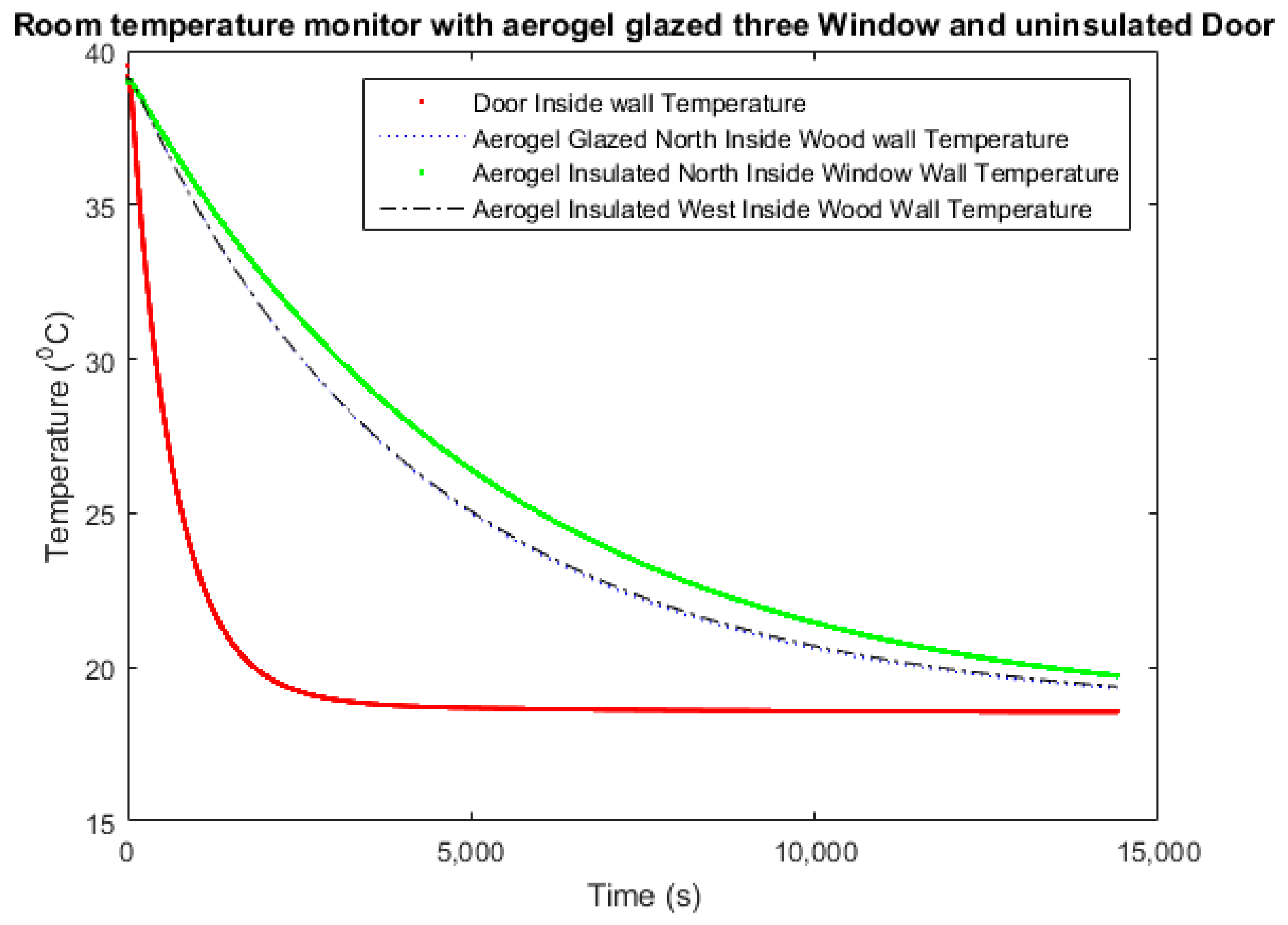
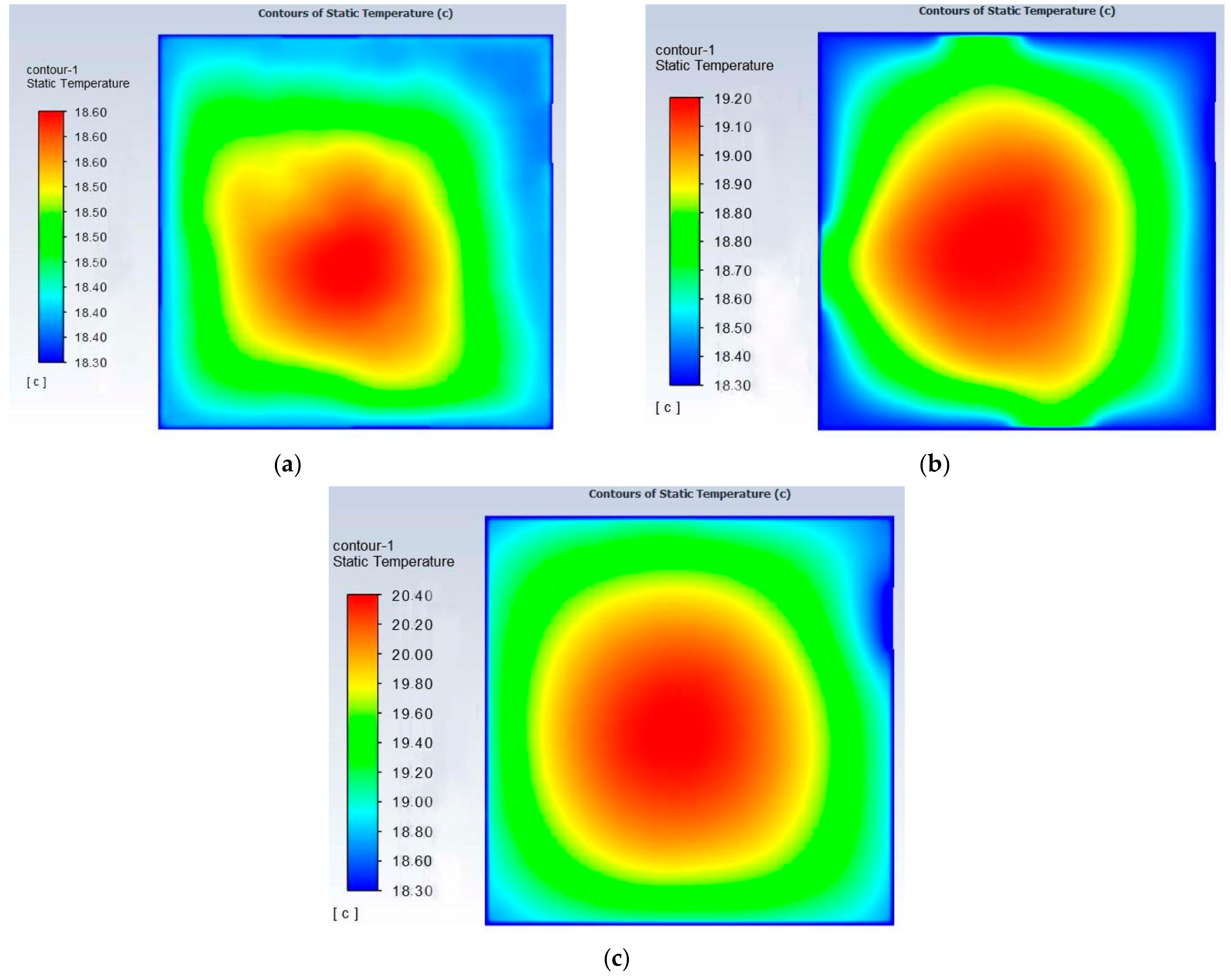
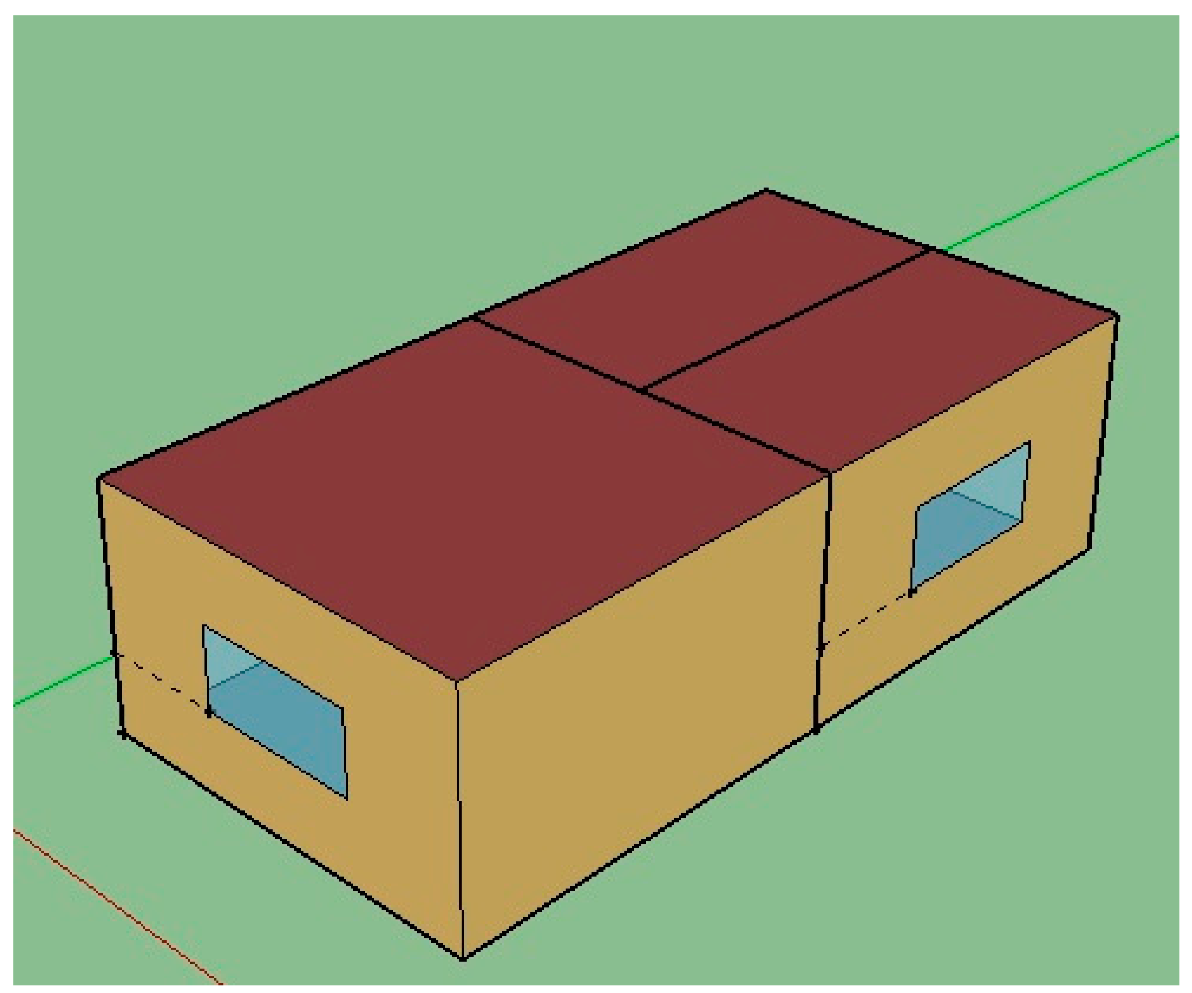
4.2. Simulation of a Room Considering Door and Window

A 1 m3 room was modelled considering a door and three windows as shown by Figure 2. The room made of aerogel-glazed windows with the aerogel-insulated wall, fiberglass-insulated wall with an argon-glazed window, and argon-glazed window with an uninsulated wall were considered for the simulation. Here, 10 mm thick aerogel was kept in between a 3 mm thick wood wall and a 3 mm thick glass layer of window. The door was not insulated in the simulation. Here, outside and inside wall temperatures were also considered 18.33 °C (291.5 K) and 41.85 °C (314 K), respectively. Figure 6 is the two-dimensional contour plot of the room made with an aerogel-glazed window with an aerogel-insulated wall, and Figure 7 is the temperature decay comparison of the room. The inside room temperature decreased with elapsing time. Additionally, the temperature decreased quickly through the door because the door is uninsulated. In Figure 6 of the room simulation, the blue color shows the lowest temperature distributed across the near wall and the highest temperature presented by red color located around the center. The temperature was monitored at the door on the inside wall, north inside window wall, north inside wall, and west inside wall. From the simulation, it is found that temperature deterioration is faster at the door, as the wood door was not insulated, and the rest of the side has a similar temperature-deterioration profile.
Figure 8 is the contour plot comparison for the room simulation of the argon-glazed window with the uninsulated wall, fiberglass-insulated wall with an argon-glazed window, and aerogel-insulated wall with an argon-glazed window. The room temperature decreased fast and un-uniformly for the room made of an uninsulated wall with an argon-glazed window. The room made of the aerogel-insulated wall with the aerogel-glazed window has higher and had a more uniform temperature distribution compared to the room of the fiberglass-insulated wall with an argon-glazed window as shown by Figure 6 and Figure 8b. Figure 9 is the temperature decay of the argon-glazed window with the uninsulated wall of the room. All temperature decay has a similar profile. Finally, the temperature decay profile was compared as shown by Figure 10. Figure 10a is the temperature degradation comparison among doors for the aerogel-glazed with an aerogel-insulated wall, argon glazed with an uninsulated wall, and argon glazed with a fiberglass-insulated wall. Figure 10b–d are the west inside wall, north inside window, and north inside wall temperature comparison, respectively. Comparing the results, it is found that the aerogel-glazed with an aerogel-insulated wall reduces more energy compared to the argon-glazed with an uninsulated wall and argon-glazed with a fiberglass-insulated wall of the room.
However, a room of the aerogel-insulated wall with the argon-glazed window was considered for the simulation. The contour plot of the aerogel-insulated wall with the argon-glazed window is shown in Figure 8c. The temperature deterioration is faster in the door of the inside wall of the aerogel-insulated wall with the argon-glazed window of the room compared to the aerogel-glazed window with the aerogel-insulated wall as shown by Figure 10a. Temperature deterioration is also slower for the aerogel-glazed window with the aerogel-insulated wall of a room in the north inside wall, north inside window, and west inside wall as shown by Figure 10b–d accordingly.

4.3. EnergyPlus Simulation of an Office

Energy analysis was conducted by considering fiberglass- and aerogel-insulated walls of an office (189.1-2009-office-OpenOffice) as shown in Figure 11 [43]. Three thermal zones were considered in the office with an area of 50 m2. In the office, three windows were also considered where one layer of 3 mm clear glass was used as a window material. A glazing system was not added for the simulation in windows because EnergyPlus does not allow the use of translucent material in windows. Additionally, walls, roof, and floor were considered to be made of the wood wall where aerogel and fiberglass insulation were used in simulations. As 10 mm thick insulation was considered with a 3 mm thick wood wall in the temperature decay CFD simulation, likewise a 10 mm thick insulation as defined in between the 3 mm thick wood walls in the EnergyPlus office simulation.
In the simulation, a variable refrigeration flow (VRF) system was considered for the cooling system. There is no heating system considered in the office because the simulation was conducted for Singapore weather conditions where the climate is tropical and a uniform temperature with high humidity existed throughout the year.
The thermostat cooling-set point of the room was defined as 25 °C where the simulation was conducted year-round starting from 1 January until 31 December. The interior light was taken as 10.65 Watt m−2, with an occupancy as 0.057 person m−2, and 7.64 Watt m−2 interior electric equipment for the EnergyPlus simulation.
The exterior equipment, gas equipment, hot water equipment, and steam equipment were not considered in the simulation. Additionally, there was no natural ventilation and duct leakage in the simulation.
The total site energy of the aerogel- and fiberglass-insulated wood wall of the office were found to be 9096.57 kWh and 9360.78 kWh, respectively, from the EnergyPlus simulation. By using aerogel insulation in the office, 264.21 kWh energy was reduced in a year compared to the fiberglass-insulated wood wall. The total source energy was 28,808.84 kWh and 29,645.60 kWh for aerogel and fiberglass insulated walls, respectively. By using aerogel insulation in the wall of the office, source energy was also reduced by 836.76 kWh.
Table 3, Table 4, Table 5 and Table 6 show the comparison for electricity consumption between the aerogel- and fiberglass-insulated office for a year. During the peak period on 6 April at time 15.30, the aerogel-insulated office reduced 383.15-watt energy compared to the fiberglass-insulated office. About 12% of total energy consumption was reduced by using aerogel insulation compared to fiberglass insulation on 6 April at 15.30. It can be concluded here that aerogel-insulated buildings reduce energy consumption compared to fiberglass-insulated walls of a building.

5. Conclusions

This paper investigated the suitability of aerogel for the application in glazing systems and wall insulation. The experimental results of temperature deterioration of the inside wall for the space loft aerogel blanket surrounded room compares fairly well with simulation results. The temperature decay simulation was compared among the rooms made of the aerogel-glazed window with an aerogel-insulated wall, fiberglass-insulated wall of a room with an argon-glazed window, argon-glazed window with an aerogel-insulated wall, and the uninsulated room along with an argon-glazed window. Temperature decay is found to be slower for the aerogel-glazed with an aerogel-insulated wall compared to the argon-glazed with fiberglass-insulated wall, argon-glazed window with aerogel-insulated wall, and argon-glazed with an uninsulated wall of a room. Heat transfer through the fiberglass-insulated wall along with an argon-glazed window is faster compared to the aerogel-insulated wall with an aerogel-glazed window.
Slower temperature decay of the aerogel-insulated wall with an aerogel-glazed window can potentially lead to reduced building energy consumption compared to a room made with commonly used fiberglass-insulated wood wall along with an argon-glazed window and a room made of an uninsulated wood wall with an argon-glazed window. The EnergyPlus simulation of the aerogel- and fiberglass-insulated wood wall were conducted throughout the year, and it is found that the aerogel-insulated room reduced energy consumption compared to the fiberglass-insulated room. It was found that the building’s annual energy consumption is reduced by 6% with the use of aerogel insulation compared to fiberglass. The total energy consumption was reduced by 12% on a peak energy consumption day. More importantly, aerogel is reusable, and it is highly suitable for both cold and hot climate conditions. The addition of the aerogel-insulated wall and an aerogel-glazed window to the building showed good potential for reducing building energy consumption.

Author Contributions

S.G. initiated the project, developed the model and conducted the experiments. R.N. provided guidance in the detailed development of the model, provided inputs and critical analysis based on the model outcomes and contributed to the development of the manuscript. M.R.H. and M.R.I. provided general inputs and comments on the manuscript. All authors have read and agreed to the published version of the manuscript.

Funding

This research received no external funding.

Data Availability Statement

Raw data were generated at the First Autor. The data that support the findings of this study are available on request from the corresponding author.

Conflicts of Interest

The authors declare no conflict of interest.

Nomenclature

U, VDimensional velocity component (m s−1)
ρ Density (kg m−3)
PDimensional pressure (Pa)
ν Kinematic viscosity (m2s−1)
gAcceleration due to gravity (9.81 ms−2)
k Thermal diffusivity (m2s−1)
β Thermal expansion coefficient (Per kelvin (K−1)
T Temperature (Celsius/Kelvin/Fahrenheit)
T 0 Reference temperature (Celsius/Kelvin/Fahrenheit)
tTime (Second/minute/hour)
x, yDimensional coordinates
QHeat Transfer (W)
AArea (m2)
KThermal conductivity (Wm−1 K−1)
q out , k Energy flux that leaves from the surface (Wt)
k Emissivity
σ Boltzmann constant (J K−1)
q in , k Incident energy flux from surroundings (W)
A and B Solar irradiation
Y Ratio of sky diffuse radiation on a vertical surface
Edn Direct normal irradiation
ϵTilt angle
Ρ g Ground reflectivity

References

  1. Narayanan, R. Heat-driven cooling technologies. In Clean Energy for Sustainable Development; Academic Press: Cambridge, MA, USA, 2017; pp. 191–212. [Google Scholar] [CrossRef]
  2. Narayanan, R.; Halawa, E.; Jain, S. Performance characteristics of solid-desiccant evaporative cooling systems. Energies 2018, 11, 2574. [Google Scholar] [CrossRef] [Green Version]
  3. Uriarte, I.; Erkoreka, A.; Eguia, P.; Granada, E.; Martin-Escudero, K. Estimation of the heat loss coefficient of two occupied residential buildings through an average method. Energies 2020, 13, 5724. [Google Scholar] [CrossRef]
  4. Rasmussen, C.; Bacher, P.; Cali, D.; Nielsen, H.A.; Madsen, H. Method for scalable and automatized thermal building performance documentation and screening. Energies 2020, 13, 3866. [Google Scholar] [CrossRef]
  5. Narayanan, R.; Halawa, E.; Jain, S. Dehumidification potential of a solid desiccant based evaporative cooling system with an enthalpy exchanger operating in subtropical and tropical climates. Energies 2019, 12, 2704. [Google Scholar] [CrossRef] [Green Version]
  6. Rucinska, J.; Trzaski, A. Measurements and simulation study of daylight availability and its impact on the heating, cooling and lighting energy demand in an educational building. Energies 2020, 13, 2555. [Google Scholar] [CrossRef]
  7. GhaffarianHoseini, A.; Dahlan, N.; Berardi, U.; GhaffarianHoseini, A.; Makaremi, N. Sustainable energy performances of green buildings: A review of current theories, implementations and challenges. Renew. Sustain. Energy Rev. 2013, 25, 1–17. [Google Scholar] [CrossRef]
  8. Jelle, B.P. Traditional, state-of-the-art and future and future thermal building insulation materials and solutions—Properties, requirements and possibilities. Energy Build. 2011, 4, 2549–2563. [Google Scholar] [CrossRef] [Green Version]
  9. Heinemann, U. Long-Term Performance of Super-Insulating Materials in Building Components and Systems; Energy in Building and Communities Program; International Energy Agency: Paris, France, 2020. [Google Scholar]
  10. Husing, N.; Schubert, U. Aerogels–airy materials: Chemistry, structure and properties. Angew. Chem. Int. Ed. 1998, 2, 22–45. [Google Scholar] [CrossRef]
  11. Jelle, B.; Hynd, A.; Gustavsen, A.; Arasteh, D.; Goudey, H.; Hart, R. Fenestration of today and tomorrow: A state–of–the–art review and future research opportunities. Sol. Energy Mater. Sol. Cells 2012, 96, 1–28. [Google Scholar] [CrossRef] [Green Version]
  12. Berardi, U. Development of glazing system with silica aerogel. Energy Procedia 2015, 78, 394–399. [Google Scholar] [CrossRef] [Green Version]
  13. Baetens, R.; Jelle, B.P.; Gustavsen, A. Aerogel insulation for building applications: A state-of-the-art review. Energy Build. 2011, 43, 761–769. [Google Scholar] [CrossRef] [Green Version]
  14. Lucci, E.; Becherini, F.; Di Tuccio, M.C.; Troi, A.; Frick, J.; Roberti, F.; Hermann, C.; Fairnington, I.; Mezzasalma, G.; Pockelé, L.; et al. Thermal performance evaluation and comfort assessment of advanced aerogel as blown-in insulation for historic buildings. Build. Environ. 2017, 122, 258–268. [Google Scholar] [CrossRef]
  15. Cuce, E.; Cuce, P.M.; Wood, C.J.; Riffat, S.B. Optimizing insulation thickness and analyzing environmental impacts of aerogel-based thermal superinsulation in buildings. Energy Build. 2014, 77, 28–39. [Google Scholar] [CrossRef]
  16. Mujeebu, M.A.; Ashraf, N.; Alsuwayigh, A. Energy performance and economic viability of nano aerogel glazing and nano vacuum insulation panel in multi-story office building. Energy 2016, 113, 949–956. [Google Scholar] [CrossRef]
  17. Li, D.; Zhang, C.; Li, Q.; Liu, C.; Arici, M.; Wu, Y. Thermal performance evaluation of glass window combining silica aerogels and phase change materials for cold climate of China. Appl. Therm. Eng. 2020, 165, 114–547. [Google Scholar] [CrossRef]
  18. Yang, Y.; Wu, H.; Yang, L.; Xu, T.; Ding, Y.; Fu, P. Thermal and day-lighting performance of aerogel glazing system in large atrium building under cooling-dominant climates. Energy Procedia 2019, 158, 6347–6357. [Google Scholar] [CrossRef]
  19. Zhao, X.; Mofid, S.A.; Al Hulayel, M.R. Reduced-scale hot box method for thermal characterization of window insulation materials. Appl. Therm. Eng. 2019, 160, 114026. [Google Scholar] [CrossRef]
  20. Paulos, J.; Berardi, U. Optimizing the thermal performance of window frames through aerogel enhancements. Appl. Energy 2020, 266, 114–776. [Google Scholar] [CrossRef]
  21. Leung, C.K.; Lu, L.; Liu, Y.; Cheng, H.S.; Tse, J.H. Optical and thermal performance analysis of aerogel glazing technology in a commercial building of Hong Kong. Energy Built Environ. 2020, 1, 215–223. [Google Scholar] [CrossRef]
  22. Berardi, U.; Kisilewicz, T.; Kim, S. Experimental and numerical investigation of the thermal transmittance of PVC window frames with silica aerogel. J. Build. Eng. 2020, 32, 101–665. [Google Scholar] [CrossRef]
  23. Lolli, N.; Andresen, I. Aerogel vs. Argon insulation in windows: A greenhouse gas emissions analysis. Build. Environ. 2016, 101, 64–76. [Google Scholar] [CrossRef]
  24. An, L.; Wang, J.; Petit, D.; Armstrong, J.N.; Li, C.; Hu, Y.; Huang, Y.; Shao, Z.; Ren, S. A scalable cross-linked fiberglass-aerogel thermal insulation composite. Appl. Mater. Today 2020, 21, 100843. [Google Scholar] [CrossRef]
  25. An, L.; Wang, J.; Petit, D.; Armstrong, J.N.; Li, C.; Hu, Y.; Huang, Y.; Shao, Z.; Ren, S. An all-ceramic, anisotropic and flexible aerogel insulation material. Nano Lett. 2020, 20, 3828–3835. [Google Scholar] [CrossRef]
  26. Yang, R.; Hu, F.; An, L.; Armstrong, J.H.; Hu, Y.; Li, C.; Huang, Y.; Ren, S. A hierarchical mesoporous insulation ceramic. Nano Lett. 2020, 20, 1110–1116. [Google Scholar] [CrossRef]
  27. Merli, F.; Anderson, A.M.; Carroll, M.K.; Buratti, C. Acoustic measurements on monolithic aerogel samples and application of the selected solutions to standard window system. Appl. Acoust. 2018, 142, 123–131. [Google Scholar] [CrossRef]
  28. Gopi, S.; Balakrishnan, P.; Geethamma, V.G.; Pius, A.; Thomas, S. Applications of cellulose nanofibrils in drug delivery. In Applications of Nanocomposite Materials in Drug Delivery; Woodhead Publishing Series in Biomaterials; Woodhead Publishing: Sawston, UK, 2018; pp. 75–95. [Google Scholar]
  29. Jensen, K.I.; Shultz, J.M.; Kristiansen, F.H. Development of windows based on highly inslating aerogel glazings. J. Non-Cryst. Solids 2004, 350, 351–357. [Google Scholar] [CrossRef]
  30. Buratii, C.; Merli, F.; Moretti, E. Aerogel-based materials for building applications: Influence of granule size on thermal and acoustic performance. Energy Build. 2017, 152, 472–482. [Google Scholar] [CrossRef]
  31. Spaceloft Insulation Technical Guide. Aspen Aerogels. Available online: http://www.aerogel.uk.com/Spaceloft_Technical_Guide_1%20.pdf (accessed on 4 January 2021).
  32. ANSYS, Inc. ANSYS Fluent Theory Guide; ANSYS, Inc.: Canonsburg, PA, USA, 2020. [Google Scholar]
  33. Riffat, S.B.; Qiu, G. A review of state-of-art aerogel application in buildings. Int. J. Low-Carbon Technol. 2012, 8, 1–6. [Google Scholar] [CrossRef]
  34. Cuce, E.; Cuce, P.M.; Wood, C.J.; Riffat, S.B. Toward aerogel based thermal superinsulation in buildings: A comprehensive review. Renew. Sustain. Energy Rev. 2014, 34, 273–299. [Google Scholar] [CrossRef]
  35. Omer, S.A.; Riffat, S.B.; Qiu, G. Technical note: Thermal insulation for hot water cylinders: A review and a conceptual evaluation. Build. Serv. Eng. Res. Technol. 2007, 28, 275–293. [Google Scholar] [CrossRef]
  36. Buy Aerogel. Available online: http://www.buyaerogel.com/product/spaceloft/#:~:text=Great%20for%20home%20insulation%2C%20winter,69%20g%20per%20square%20foot (accessed on 4 January 2021).
  37. Holman, J.P. Heat Transfer, 10th ed.; McGraw-Hill: New York, NY, USA, 2009. [Google Scholar]
  38. Young, H.D.; Freedman, R.A.; Ford, A.L.; Sandin, T.R. Sears and Zemansky’s University Physics, 10th ed.; Addison Wesley Longman: Boston, MA, USA, 1999. [Google Scholar]
  39. Aldawi, F.; Alam, F. Residential building wall systems: Energy efficiency and carbon footprint. In Thermofluid Modeling for Energy Efficiency Applications; Academic Press: Cambridge, MA, USA, 2016; pp. 169–196. [Google Scholar] [CrossRef]
  40. Gao, G.; Li, Y.; Jing, Z.; Yuan, S. Experimental investigation on thermal physical properties on an advanced glass fiber composite material. Phys. Procedia 2012, 25, 339–344. [Google Scholar] [CrossRef] [Green Version]
  41. Holman, J.P. Heat Transfer, 9th ed.; McGraw-Hill: New York, NY, USA, 2002. [Google Scholar]
  42. Cushman, B.; Beckers, J.-M. Introduction to geophysical fluid dynamics. Int. Geophys. 2011, 101, 99–129. [Google Scholar]
  43. Lawrence Berkeley National Laboratory, EnergyPlus Engineering Reference, 30 September 2016, p. 149. Available online: https://energyplus.net/sites/all/modules/custom/nrel_custom/pdfs/pdfs_v8.6.0/EngineeringReference.pdf (accessed on 4 January 2021).
Figure 1. Experimental box covered with aerogel insulation blanket.
Energies 14 03310 g001
Figure 2. Schematic drawing of a room for CFD Simulation.
Energies 14 03310 g002
Figure 3. Comparison between wall temperature results of experiment and simulation.
Energies 14 03310 g003
Figure 4. CFD simulation for window. (a): Comparison of wall temperature of glazing with different thickness. (b): Temperature decay with solar ray tracing model for two types of windows.
Energies 14 03310 g004
Figure 5. Temperature degradation comparison between aerogel-glazed and argon-glazed box at the monitored point of (0.84 m, 0.5 m, 0.5 m).
Energies 14 03310 g005
Figure 6. Contour plot of a room with aerogel glazed window and aerogel insulated wall.
Energies 14 03310 g006
Figure 7. Temperature deterioration profile of aerogel-glazed window and aerogel-insulated room.
Energies 14 03310 g007
Figure 8. Contour plot comparison among argon-glazed window with uninsulated, fiberglass-insulated wall of a room with argon-glazed window and aerogel-insulated room with argon-glazed window. (a): Argon-glazed window with uninsulated wall. (b): Argon-glazed window with fiberglass-insulated wall. (c): Aerogel-insulated room with argon-glazed window.
Energies 14 03310 g008
Figure 9. Temperature decay monitor for argon-glazed window with uninsulated wall of the room.
Energies 14 03310 g009
Figure 10. Temperature deterioration comparison between aerogel-glazed and insulated room and argon-glazed and uninsulated room. (a): Door temperature comparison. (b): West inside wall temperature comparison. (c): North inside window temperature comparison. (d): North inside wall temperature comparison.
Energies 14 03310 g010
Figure 11. Office for the EnergyPlus simulation.
Energies 14 03310 g011
Table 1. Thermal properties for materials used in the research below [36,37,38,39,40,41].
Material/GasDensity
(kg m−3)
Specific Heat
(J kg−1 K−1)
Thermal Conductivity
(W m−1 K−1)
Space loft aerogel15010000.014
Glass27008400.8
Argon1.6228520.640.0158
Air1.2251006.430.0242
Wood70023100.173
Fiber Glass1216200.04
Table 2. Optical and thermal properties [21].
DescriptionU-Value (Wm−2K−1)Solar Heat Gain Coefficient (SHGC)Transmittance (Tvis)
Aerogel-glazing (1 mm aerogel particle with 16 mm filling-thickness)2.0650.3460.058
3 mm standard glass5.80.870.86
Table 3. Electricity consumption of the office for a year.
AspectAerogel-Insulated OfficeFiberglass-Insulated OfficeEnergy Reduction by Using Aerogel InsulationEnergy Consumption Reduction (%)
Cooling (kWh)4088.574344.67256.16
Interior light (kWh)1723.811723.8100
Interior Equipment (kWh)3126.923126.9200
Fans (kWh)157.26165.378.115
HVAC (kW m−2)84.9290.205.286
Table 4. Electricity consumption comparison of the office during peak time (6 April at time 15.30).
AspectAerogel-Insulated OfficeFiberglass-Insulated OfficeEnergy Reduction by Using Aerogel InsulationEnergy Consumption Reduction (%)
Cooling (W)1754.882129.65374.7718
Interior light (W)479.53479.5300
Interior Equipment (W)493.91493.9100
Fans (W)45.9654.338.3715
Table 5. Total source Energy Comparison for the year.
AspectAerogel-Insulated OfficeFiberglass-Insulated OfficeEnergy Reduction by Using Aerogel InsulationEnergy Consumption Reduction (%)
Cooling (kWh)12,948.5113,759.58811.076
Interior light (kWh)5459.315459.3100
Interior Equipment (kWh)9902.979902.9700
Fans (kWh)498.04523.7425.75
Table 6. Source Energy Comparison per conditioned floor area.
AspectAerogel-Insulated OfficeFiberglass-Insulated OfficeEnergy Reduction by Using Aerogel Insulation (%)
Cooling (kWh)258.97275.196
Interior light (kWh)109.19109.190
Interior Equipment (kWh)198.06198.060
Fans (kWh)9.9610.475
Publisher’s Note: MDPI stays neutral with regard to jurisdictional claims in published maps and institutional affiliations.

