
Efficient Control of DC Microgrid with Hybrid PV—Fuel Cell and Energy Storage Systems


 ,
, 
 ,
, 
Abstract
1. Introduction
2. Mathematical Model of Solar PV and Fuel Cell
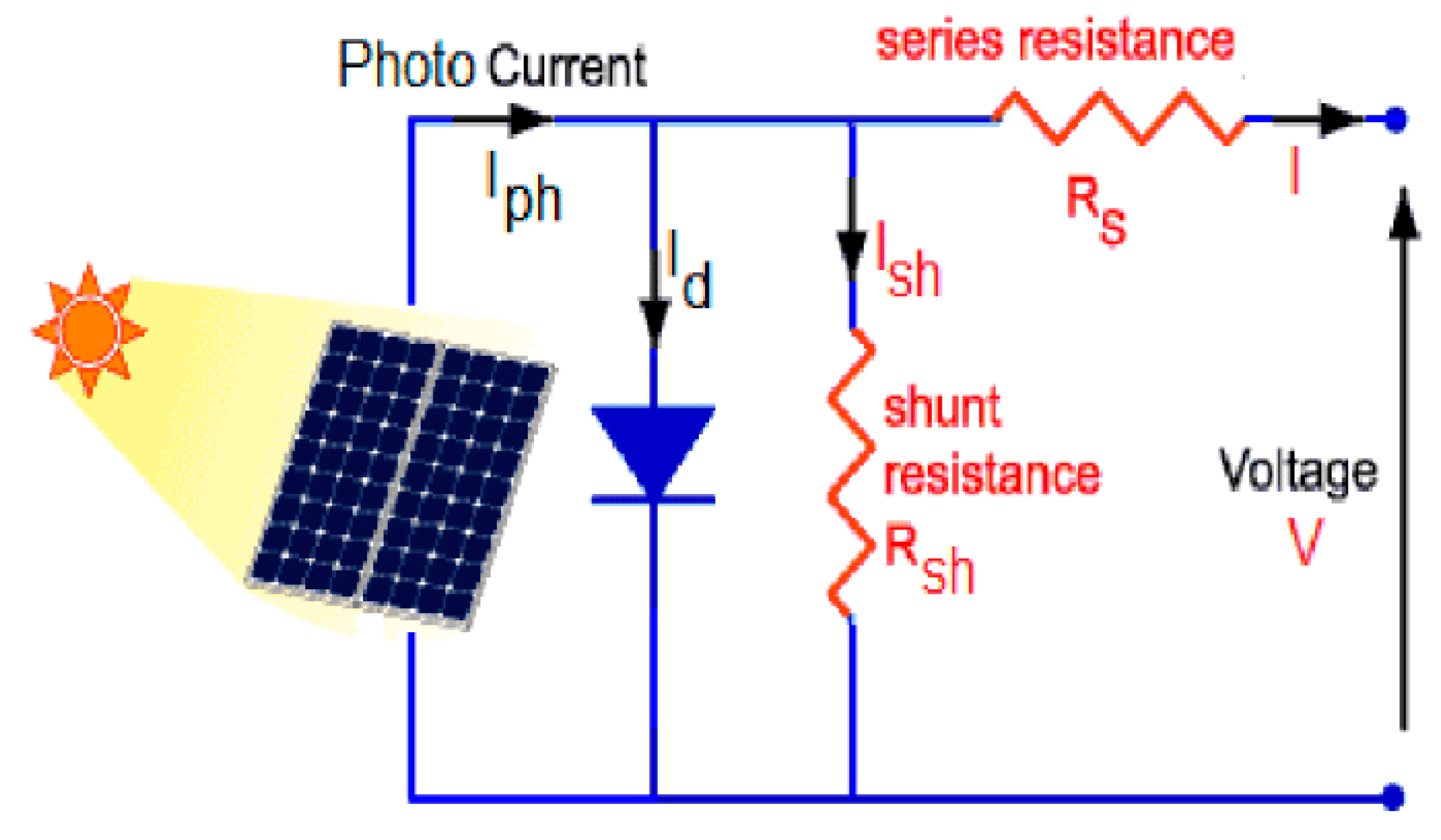
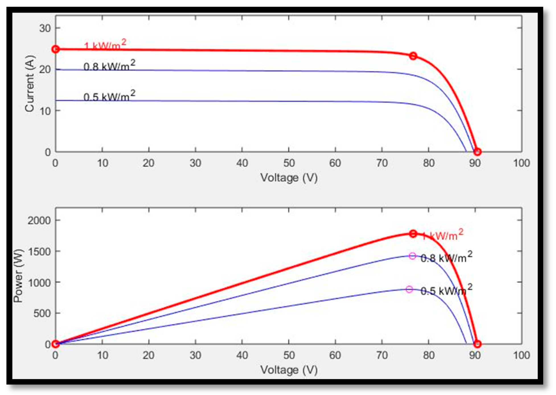
2.1. Modelling of Solar PV
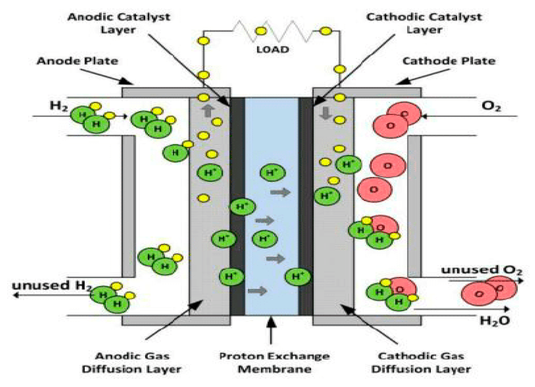
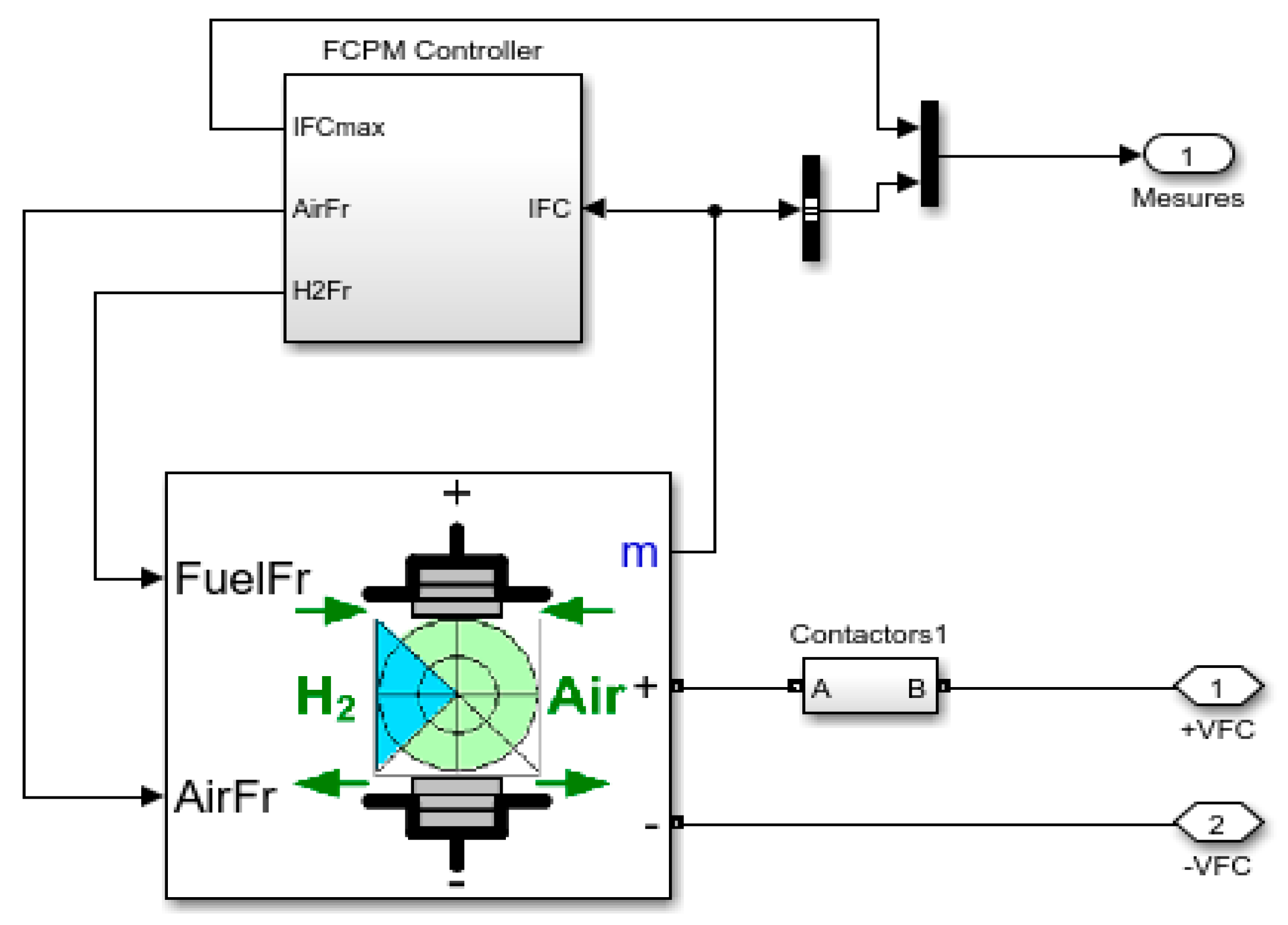
2.2. FC Mathematical Model
2.2.1. Model Equations of FC
2.2.2. Continuity Equation
2.2.3. Momentum Conservation
2.2.4. Conversion of Charge Equation
2.2.5. Electrochemical Reaction Dynamics equation
3. MPPT Techniques
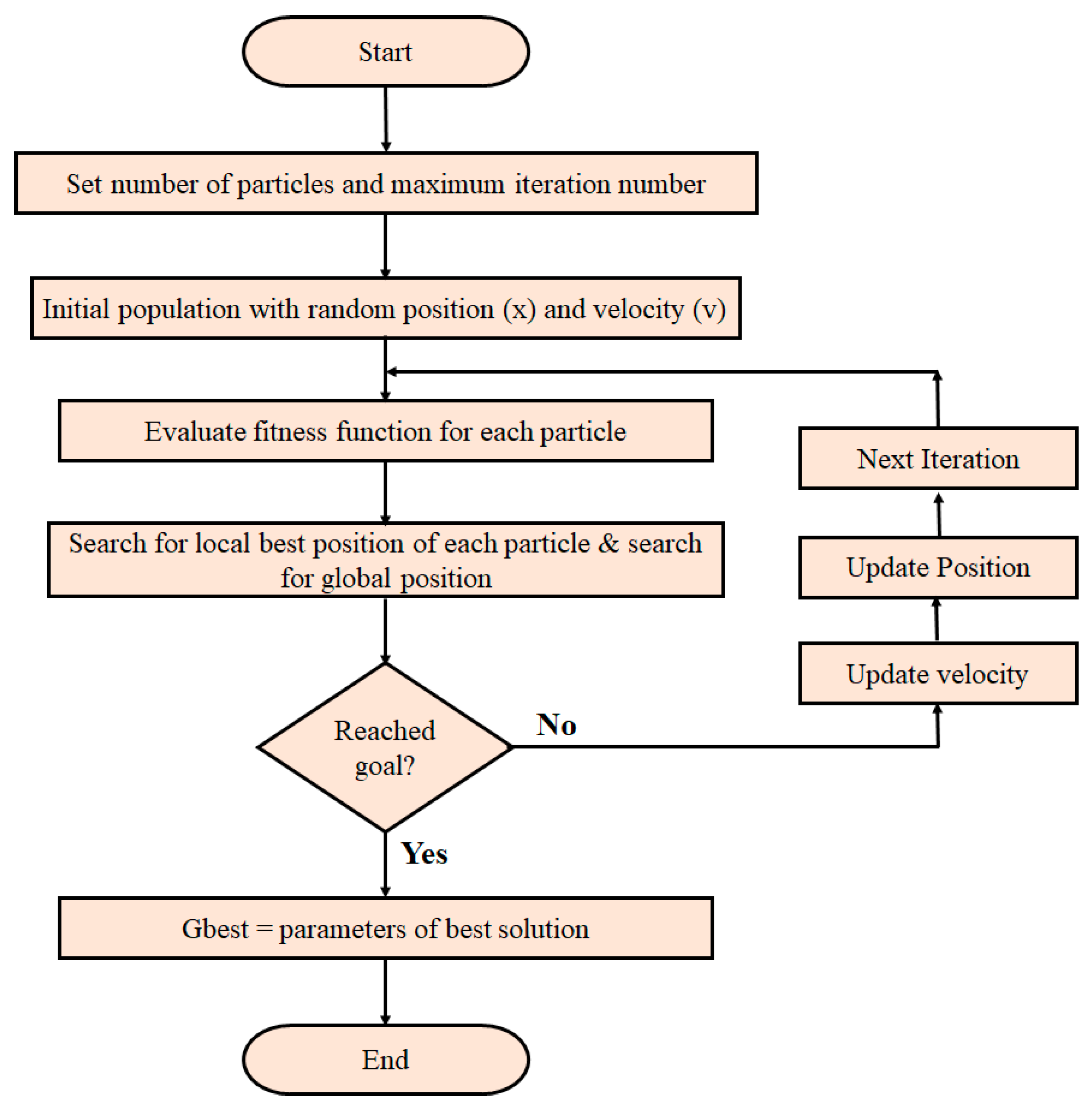
3.1. Particle Swarm Optimization (PSO)
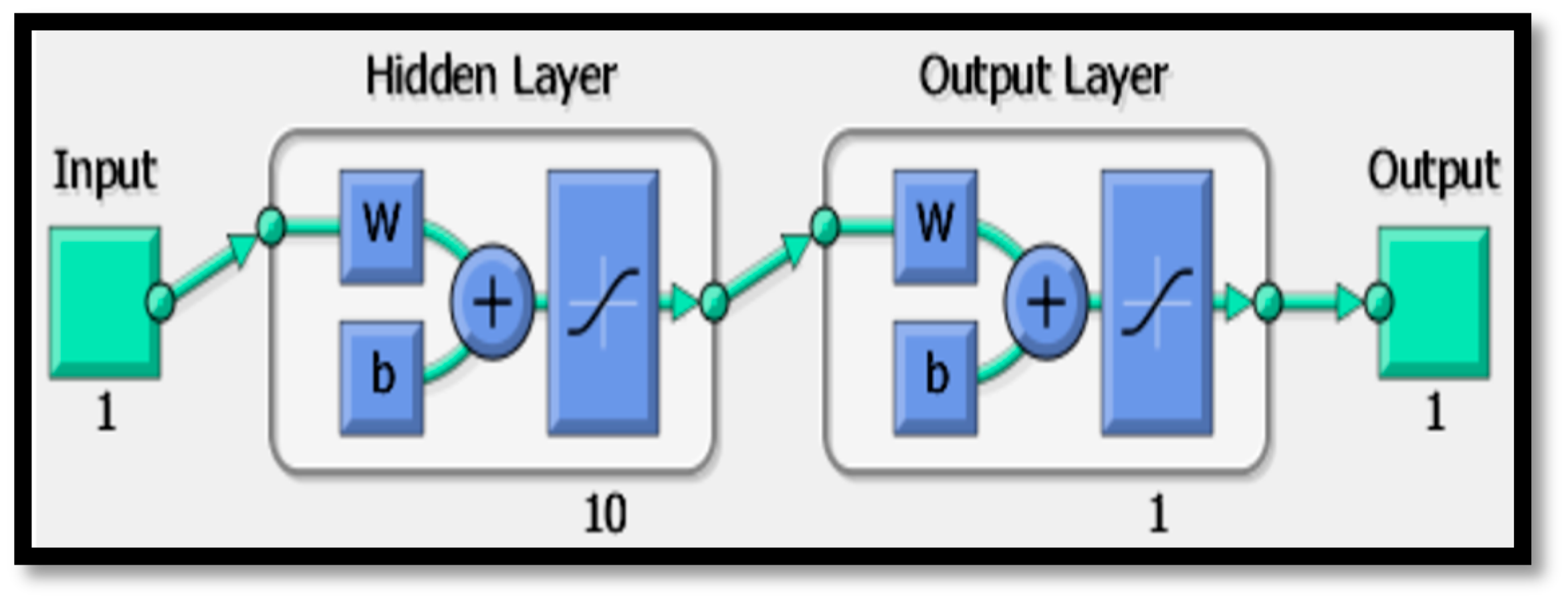
3.2. Artificial Neural Network
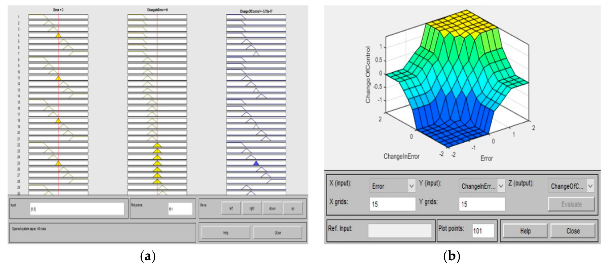
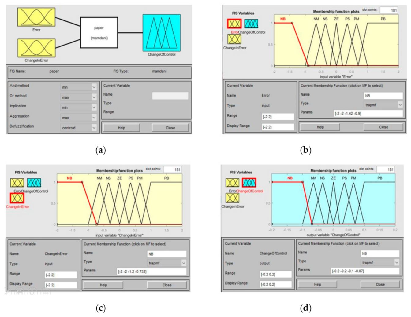
3.3. Fuzzy Logic Controller
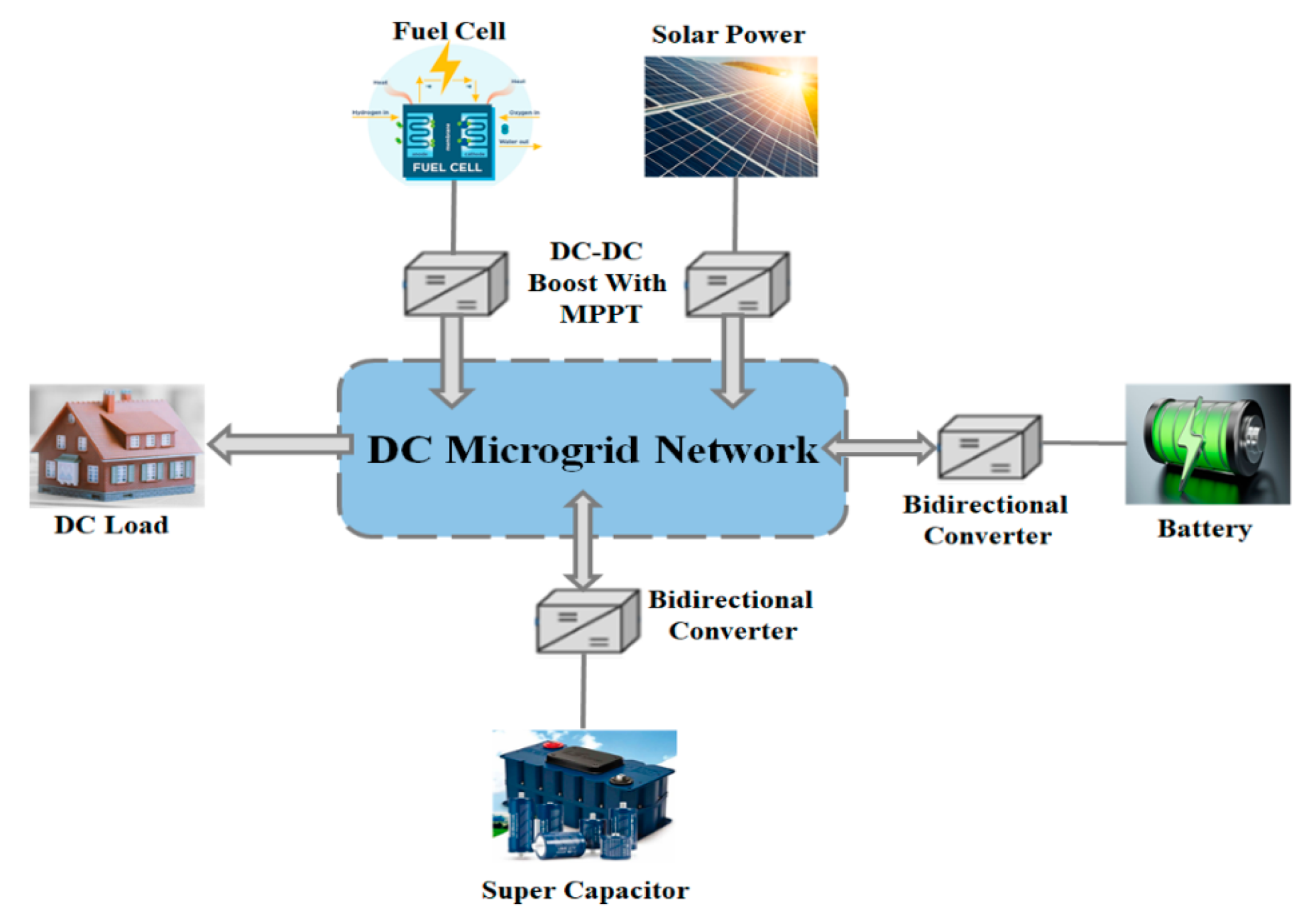
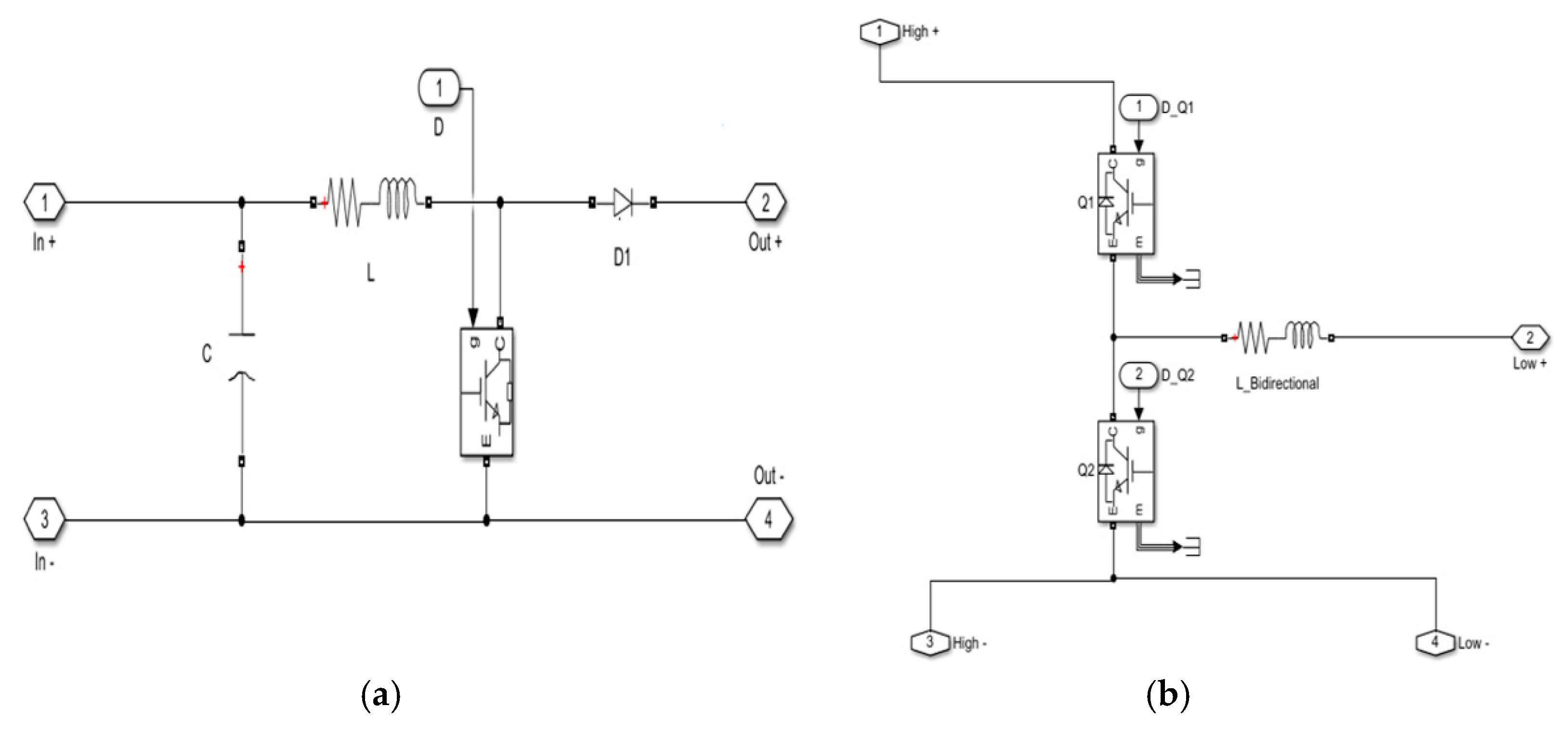
4. Simulink model of DC Microgrid
5. Conclusions
Author Contributions
Funding
Institutional Review Board Statement
Informed Consent Statement
Data Availability Statement
Conflicts of Interest
References
- Gandini, D.; de Almeida, A.T. Direct current microgrids based on solar power systems and storage optimization, as a tool for cost-effective rural electrification. Renew. Energy 2017, 111, 275–283. [Google Scholar] [CrossRef]
- Hirsch, A.; Parag, Y.; Guerrero, J. Microgrids: A review of technologies, key drives and outstanding issues. Renew. Sustian. Energy Rev. 2018, 90, 402–411. [Google Scholar] [CrossRef]
- Liu, Z.; Su, M.; Sun, Y.; Yuan, W.; Han, H.; Feng, J. Existence and Stability of Equilibrium of DC Microgrid with Constant Power Loads. IEEE Trans. Power Syst. 2018, 33, 6999–7010. [Google Scholar] [CrossRef]
- Cheng, Z.; Li, Z.; Li, S.; Gao, J.; Si, J.; Das, H.S.; Dong, W. A novel cascaded control to improve stability and inertia of parallel buck-boost converters in DC microgrid. Int. J. Electr. Power Energy Syst. 2020, 119, 105950. [Google Scholar] [CrossRef]
- Eid, A. Utility integration of PV-wind-fuel cell hybrid distributed generation systems under variable load demands. Int. J. Electr. Power Energy Syst. 2014, 62, 689–699. [Google Scholar] [CrossRef]
- Srinivasan, M.; Kwasinski, A. Control analysis of parallel DC-DC converters in a DC microgrid with constant power loads. Int. J. Electr. Power Energy Syst. 2020, 122, 106207. [Google Scholar] [CrossRef]
- Liu, Z.; Zhao, J.; Zou, Z. Impedance Modeling, dynamic Analysis and damping enhancement for DC Microgrid with multiple types of loads. Electr. Power Energy Syst. 2020, 122, 1–12. [Google Scholar] [CrossRef]
- Armghan, H.; Yang, M.; Wang, M.; Ali, N.; Armghan, A. Nonlinear integral backstepping based control of a DC microgrid with renewable generation and energy storage systems. Int. J. Electr. Power Energy Syst. 2020, 117, 105613. [Google Scholar] [CrossRef]
- Ahmed, O.A.; Bleijs, J.A.M. Power Flow Control Methods for an Ultra capacitor Bidirectional Converter in DC Microgrids–A Comparative Study. Renew. Sustian. Energy Rev. 2013, 26, 727–738. [Google Scholar] [CrossRef]
- Arif, M.T.; Oo, A.M.T.; Ali, A.B.M.S.; Safiullah, G.M. Significance of storage on solar photovoltaic system–A Residential load case study in Australia. Smart Grid Renew. Energy 2013, 4, 167–180. [Google Scholar] [CrossRef]
- Kyriakarakos, G.; Dounis, A.I.; Arvanitis, K.G.; Papadakis, G. A fuzzy logic energy management system for polygeneration microgrids. Renew. Energy 2012, 41, 315–327. [Google Scholar] [CrossRef]
- Yaici, W.; Entchev, E. Adaptive Neuro-Fuzzy Inference System modelling for performance prediction of solar thermal energy system. Renew. Energy 2016, 86, 302–315. [Google Scholar] [CrossRef]
- Oshaba, A.S.; Ali, E.S.; Elazim, S.M.A. PI controller design for MPPT of photovoltaic system supplying SRM via BAT search algorithm. Neural Comput. Appl. 2017, 28, 651–667. [Google Scholar] [CrossRef]
- Venkateswari, R.; Sreejith, S. Factors influencing the efficiency of photovoltaic system. Renew. Sustain. Energy Rev. 2019, 101, 376–394. [Google Scholar] [CrossRef]
- Youssef, A.; El Telbany, M.; Zekry, A. Reconfigurable generic FPGA implementation of fuzzy logic controller for MPPT of PV systems. Renew. Sustain. Energy Rev. 2018, 82, 1313–1319. [Google Scholar] [CrossRef]
- Enany, M.A.; Farahat, M.A.; Nasr, A. Modeling and evaluation of main maximum power point tracking algorithms for photovoltaics systems. Renew. Sustain. Energy Rev. 2016, 58, 1578–1586. [Google Scholar] [CrossRef]
- Babaa, S.E.; Armstrong, M.; Pickert, V. Overview of Maximum Power Point Tracking Control Methods for PV systems. J. Power Energy Eng. 2014, 2, 59–72. [Google Scholar] [CrossRef]
- Costano, L.; Vitelli, M. A Novel MPPT technique for single stage grid connected PV systems: T4S. Energies 2019, 12, 4501. [Google Scholar] [CrossRef]
- Khan, M.J.; Mathew, L. Fuzzy logic controller-based MPPT for hybrid photo-voltaic/wind/fuel cell power system. Neural Comput. Appl. 2018, 31, 6331–6344. [Google Scholar] [CrossRef]
- Kharb, R.K.; Shimi, S.; Chatterji, S.; Ansari, F. Modeling of solar PV module and maximum power point tracking using ANFIS. Renew. Sustain. Energy Rev. 2014, 33, 602–612. [Google Scholar] [CrossRef]
- Rezvani, A.; Gandomkar, M. Simulation and control of intelligent photovoltaic system using new hybrid fuzzy-neural method. Neural Comput. Appl. 2016, 28, 2501–2518. [Google Scholar] [CrossRef]
- Deniz, E. ANN-based MPPT algorithm for solar PMSM drive system fed by direct-connected PV array. Neural Comput. Appl. 2016, 28, 3061–3072. [Google Scholar] [CrossRef]
- Yap, W.K.; Karri, V. An off-grid hybrid PV/diesel model as a planning and design tool, incorporating dynamic and ANN modelling techniques. Renew. Energy 2015, 78, 42–50. [Google Scholar] [CrossRef]
- Sundarabalan, C.K.; Puttagunta, Y.; Vignesh, V. Fuel cell integrated unified power quality conditioner for voltage and current reparation in four-wire distribution grid. IET Smart Grid 2019, 2, 60–68. [Google Scholar] [CrossRef]
- Liu, H.; Chen, J.; Hissel, D.; Su, H. Short–term Prognostics of PEM Fuel Cells: A Comparative and Improvement Study. IEEE Trans. Ind. Electron. 2019, 66, 6077–6086. [Google Scholar] [CrossRef]
- Garcia, P.; Garcia, C.A.; Fernandez, L.M.; Llorens, F.; Jurado, F. ANFIS-Based Control of a Grid-Connected Hybrid System Integrating Renewable Energies, Hydrogen and Batteries. IEEE Trans. Ind. Inform. 2013, 10, 1107–1117. [Google Scholar] [CrossRef]
- Daud, W.; Rosli, R.; Majlan, E.H.; Hamid, S.; Mohamed, R.; Husaini, T. PEM fuel cell system control: A review. Renew. Energy 2017, 113, 620–638. [Google Scholar] [CrossRef]
- Osório, G.; Matias, J.; Catalão, J.P.S. Short-term wind power forecasting using adaptive neuro-fuzzy inference system combined with evolutionary particle swarm optimization, wavelet transform and mutual information. Renew. Energy 2015, 75, 301–307. [Google Scholar] [CrossRef]
- Bharti, O.P.; Saket, R.K.; Nagar, S.K. Controller design for doubly fed induction generator using particle swarm optimization technique. Renew. Energy 2017, 114, 1394–1406. [Google Scholar] [CrossRef]
- Kerdphol, T.; Qudaih, Y.; Mitani, Y. Optimum battery energy storage system using PSO considering dynamic demand response for microgrids. Int. J. Electr. Power Energy Syst. 2016, 83, 58–66. [Google Scholar] [CrossRef]
- Aldair, A.A.; Obed, A.A.; Halihal, A.F. Design and implementation of ANFIS-reference model controller based MPPT using FPGA for photovoltaic system. Renew. Sustain. Energy Rev. 2018, 82, 2202–2217. [Google Scholar] [CrossRef]
- Ozçelep, Y.; Sevgen, S.; Samli, R. A study on the hydrogen consumption calculation of proton exchange membrane fuel cells for linearly increasing loads: Artificial Neural Network vs. Multiple linear regression. Renew. Energy 2020, 156, 570–578. [Google Scholar] [CrossRef]
- Chaabene, M.; Ben Ammar, M. Neuro-fuzzy dynamic model with Kalman filter to forecast irradiance and temperature for solar energy systems. Renew. Energy 2008, 33, 1435–1443. [Google Scholar] [CrossRef]
- Silveira, A.M.; Araújo, R.E. A new approach for the diagnosis of different types of faults in dc–dc power converters based on inversion method. Electr. Power Syst. Res. 2020, 180, 106103. [Google Scholar] [CrossRef]
- Yilmaz, U.; Kircay, A.; Borekci, S. PV system fuzzy logic MPPT method and PI control as a charge controller. Renew. Sustain. Energy Rev. 2018, 81, 994–1001. [Google Scholar] [CrossRef]
- Ozdemir, S.; Altin, N.; Sefa, I. Fuzzy logic based MPPT controller for high conversion ratio quadratic boost converter. Int. J. Hydrogen Energy 2017, 42, 17748–17759. [Google Scholar] [CrossRef]
- Danandeh, M.; Mousavi, S.M. Comparative and comprehensive review of maximum power point tracking methods for PV cells. Renew. Sustain. Energy Rev. 2018, 82, 2743–2767. [Google Scholar] [CrossRef]
- Yilmaz, U.; Turksoy, O.; Teke, A. Improved MPPT method to increase accuracy and speed in photovoltaic systems under variable atmospheric conditions. Electr. Power Energy Syst. 2019, 113, 634–651. [Google Scholar] [CrossRef]


| E(k) | NB | NM | NS | ZE | PS | PM | PB |
|---|---|---|---|---|---|---|---|
| ∆E(k) | |||||||
| NB | ZE | ZE | NS | NM | PM | PM | PB |
| NM | ZE | ZE | ZE | NS | PS | PM | PB |
| NS | ZE | ZE | ZE | ZE | PS | PM | PB |
| ZE | NB | NM | NM | ZE | PS | PM | PB |
| PS | PB | NM | NM | ZE | ZE | ZE | ZE |
| PM | NB | NM | NM | PS | ZE | ZE | ZE |
| PB | NB | NM | NM | PM | PS | ZE | ZE |
| Parameters | Values | Name of the Component |
|---|---|---|
| Temperature | 25 °C | Solar PV Module |
| Irradiance | 1000 W/m2 | |
| Series Connected Modules Per String | 2 | |
| Parallel Strings | 4 | |
| Open Circuit Voltage | 21 V | |
| Short Circuit Current | 8 A | |
| Number of Cells | 65 | Fuel Cell |
| Nominal Stack Efficiency | 55% | |
| Operating Temperature | 65 °C | |
| Nominal Air Flow Rate | 300 1pm | |
| Nominal Supply Pressure | Fuel—1.5 bar | |
| Air—1 bar | ||
| Nominal Composition | 99.95 H2, 21 O2, 1 H2O in % | |
| Fuel Cell Resistance | 0.07833 Ω | |
| Nerst Voltage of one Cell | 1.1288 V | |
| Input Resistance | 0.005 Ω | Boost Converter |
| Inductor | 3 mH | |
| Input Capacitor | 0.02 μF | |
| IGBT | 1 No. | |
| DC–Link | 300 μF | |
| Input Inductance | 1.5 mH | DC-DC Bidirectional Converter |
| IGBT | 2 Nos. | |
| Output Resistance | 0.5 Ω | |
| Output Inductance | 0.35 mH | |
| Rated Capacitance | 29 F | Super Capacitor |
| Equivalent DC Series Resistance | 0.03 Ω | |
| Rated Voltage | 32 V | |
| Number Series Capacitor | 1 | |
| Number of Parallel Capacitor | 1 | |
| Initial Voltage | 32 V | |
| Operating Temperature | 25 °C | |
| Type | lithium-Ion | Battery |
| Nominal Voltage | 24 V | |
| Rated capacity | 14 Ah | |
| Initial state-of-charge | 50% | |
| Cut-off voltage | 18 V |
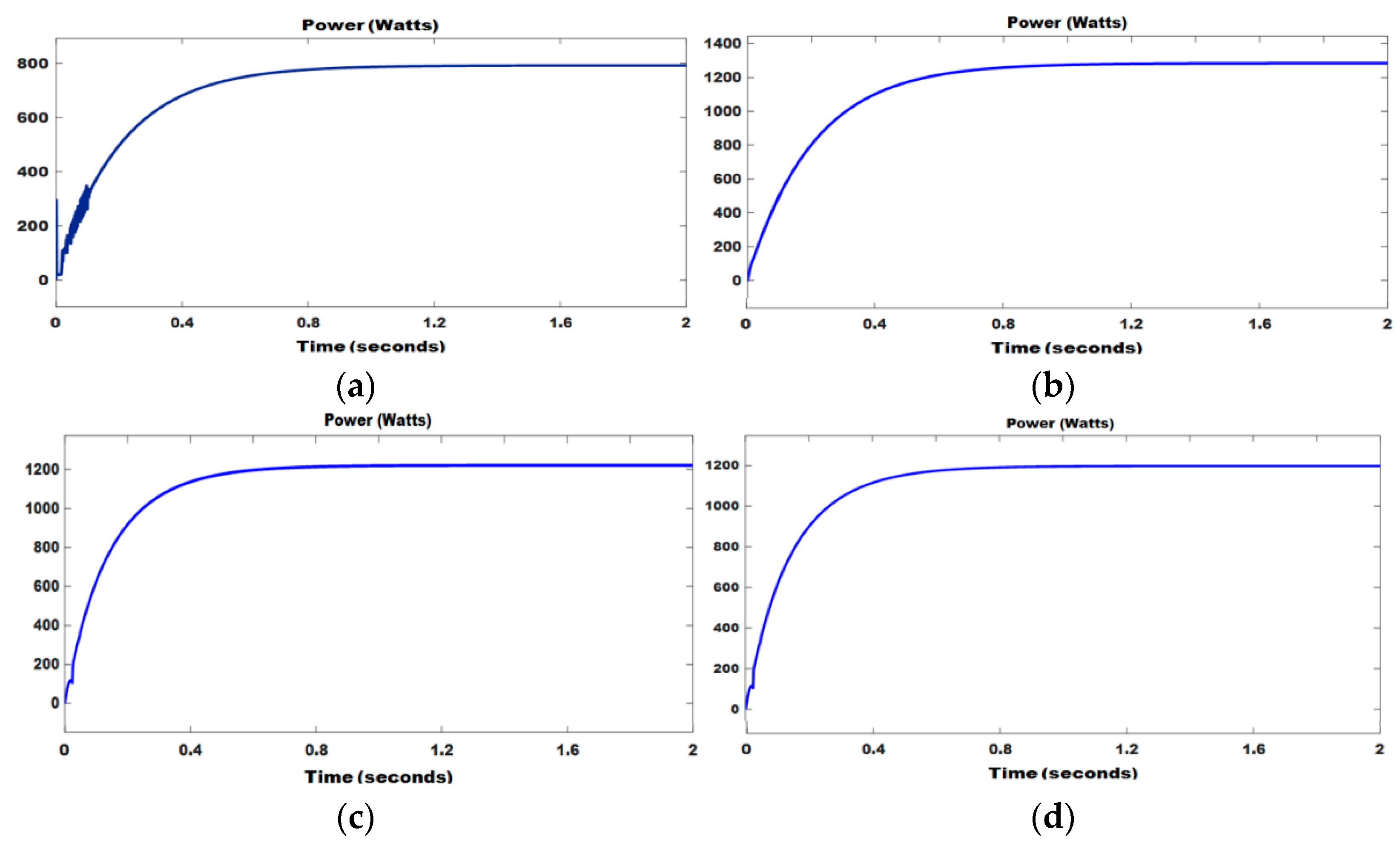
| Sources | Power (Watt) | |||
|---|---|---|---|---|
| Without MPPT | With MPPT Control | |||
| FLC | ANN | PSO | ||
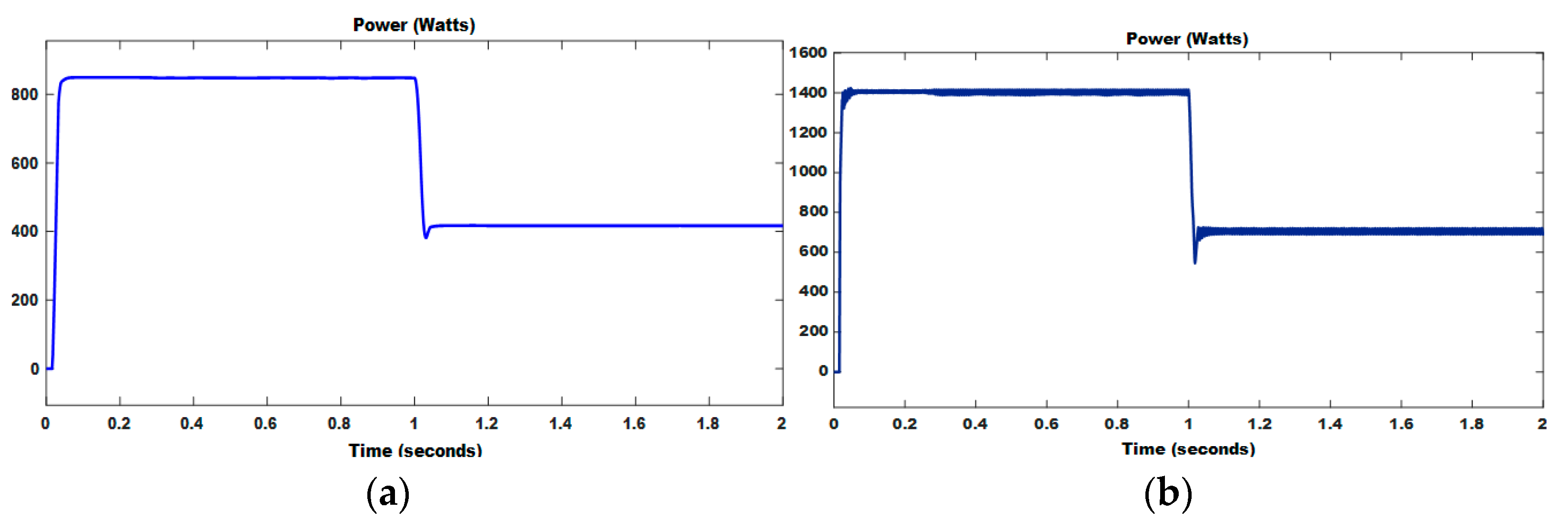
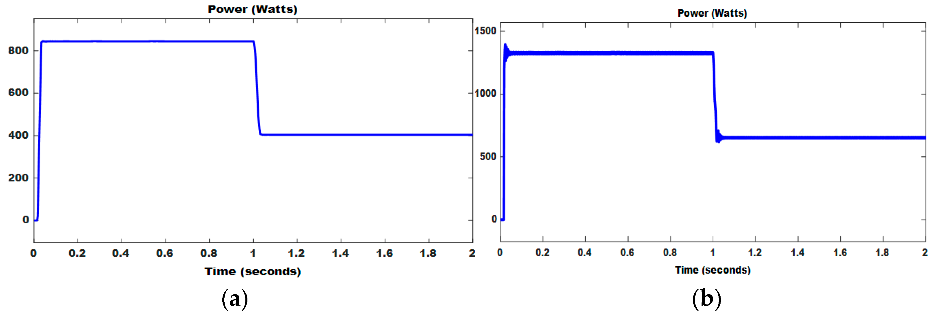
| PV | 845 | 1402 | 1335 | 1260 |
| FC | 787 | 1278 | 1208 | 1194 |
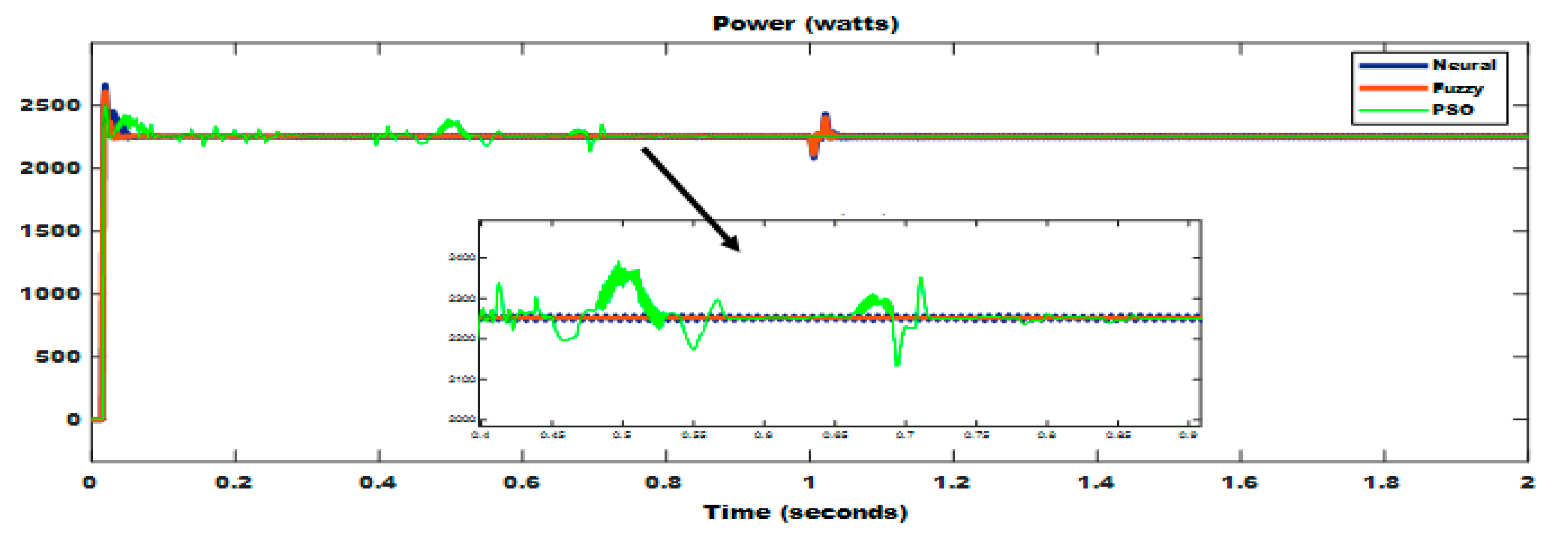
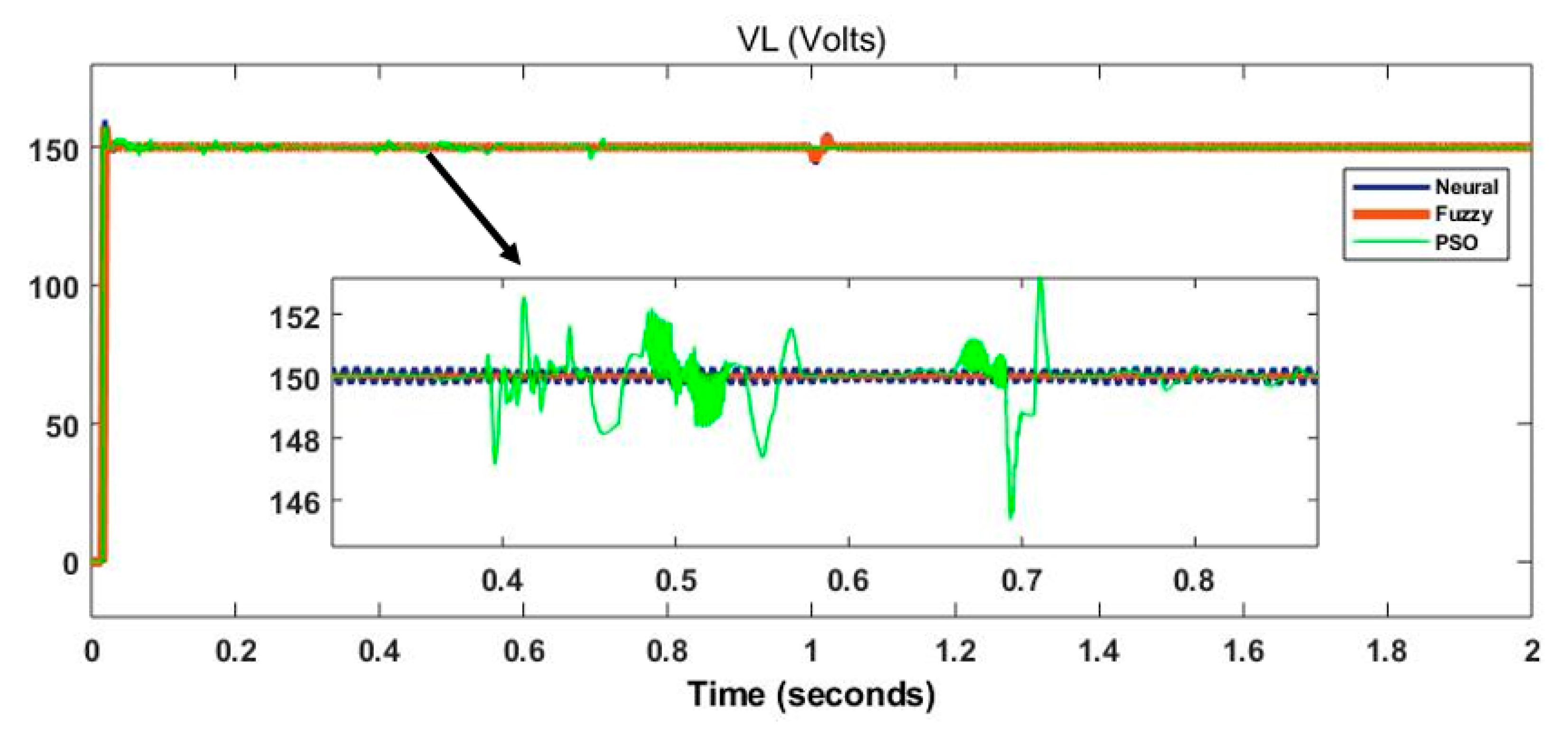
| Control Technique | Performance Parameters after MPPT | ||
|---|---|---|---|
| Under Shoot (W) | Over Shoot (W) | Settling Time (s) | |
| PSO | 1442 | 1667 | 0.650 |
| Neural Network | 1490 | 1775 | 0.054 |
| Fuzzy | 1491 | 1735 | 0.035 |
Publisher’s Note: MDPI stays neutral with regard to jurisdictional claims in published maps and institutional affiliations. |
© 2021 by the authors. Licensee MDPI, Basel, Switzerland. This article is an open access article distributed under the terms and conditions of the Creative Commons Attribution (CC BY) license (https://creativecommons.org/licenses/by/4.0/).
Share and Cite
Vasantharaj, S.; Indragandhi, V.; Subramaniyaswamy, V.; Teekaraman, Y.; Kuppusamy, R.; Nikolovski, S. Efficient Control of DC Microgrid with Hybrid PV—Fuel Cell and Energy Storage Systems. Energies 2021, 14, 3234. https://doi.org/10.3390/en14113234
Vasantharaj S, Indragandhi V, Subramaniyaswamy V, Teekaraman Y, Kuppusamy R, Nikolovski S. Efficient Control of DC Microgrid with Hybrid PV—Fuel Cell and Energy Storage Systems. Energies. 2021; 14(11):3234. https://doi.org/10.3390/en14113234
Chicago/Turabian StyleVasantharaj, Subramanian, Vairavasundaram Indragandhi, Vairavasundaram Subramaniyaswamy, Yuvaraja Teekaraman, Ramya Kuppusamy, and Srete Nikolovski. 2021. "Efficient Control of DC Microgrid with Hybrid PV—Fuel Cell and Energy Storage Systems" Energies 14, no. 11: 3234. https://doi.org/10.3390/en14113234
APA StyleVasantharaj, S., Indragandhi, V., Subramaniyaswamy, V., Teekaraman, Y., Kuppusamy, R., & Nikolovski, S. (2021). Efficient Control of DC Microgrid with Hybrid PV—Fuel Cell and Energy Storage Systems. Energies, 14(11), 3234. https://doi.org/10.3390/en14113234