Article

Research on the Optimization Design of Solar Energy-Gas-Fired Boiler Systems for Decentralized Heating

1
School of Environmental Science and Engineering, Tianjin University, Tianjin 300350, China
2
Key Laboratory of Efficient Utilization of Low and Medium Grade Energy, Tianjin University, Ministry of Education of China, Tianjin 300350, China
*
Author to whom correspondence should be addressed.
Energies 2021, 14(11), 3195; https://doi.org/10.3390/en14113195
Submission received: 28 March 2021 / Revised: 27 May 2021 / Accepted: 27 May 2021 / Published: 30 May 2021

Abstract

:
Solar energy-gas-fired boiler heating systems attract widespread attention due to their eco-friendly technologies and reasonable prices. In order to promote the application of a solar energy-gas-fired boiler system for decentralized heating, this study proposed a holistic method to optimize the combination of equipment specifications and control strategies of the system. A detailed mathematical model of the hybrid energy system was developed and validated by experiments to simulate various operating conditions and evaluate the optimal design results. A case study was conducted in Tianjin, China, and optimal schemes were obtained. The influence of different factors on the system’s annual comprehensive energy efficiency ratio (AEER) and annual cost (AC) were studied by sensitivity analysis; the results showed that the solar collector area was extremely valuable for the optimization of AEER and AC. The results of this study provide a reference for the optimization design of the solar energy-gas-fired boiler system, which is beneficial to the promotion of the utilization of solar energy.

1. Introduction

Buildings are responsible for 36% of global energy consumption and nearly 40% of carbon dioxide emissions, and space heating accounts for 53% of building energy use [1,2]. Meanwhile, with the progress of society and the development of the economy, the heating demand in regions with no central heating is growing and gradually expanding [3,4]. Moreover, most of the current heating and hot water supply systems consume non-renewable energy, which are not conducive to sustainable development. Therefore, seeking suitable alternative heating solutions, such as decentralized heating systems with renewable energy, which can minimize energy consumption and carbon emissions, while improving thermal comfort for areas where central heating cannot be used, has become a challenge.
Of the many potential renewable heating solutions, solar heating technology has been widely used in recent decades due to its pollution-free and energy-saving advantages [5,6], and it acts a pivotal part in the domestic sector in many countries. Numerous studies concentrate on the development of this technology, including the system operation strategy [7,8,9], new heat transfer fluid [10,11,12], system structure optimization [13,14], system integration [15,16], etc. Among them, the hybrid energy system is regarded as promising, because it can combine the advantages of different energy sources [17,18]. The integration system makes rational use of solar energy with other energies, such as geothermal energy [19,20], fossil energy [21], biomass energy [22], wind energy [23], and electricity energy [24], which provide flexible supplements to the solar thermal utilization.
On the other hand, gas-fired boilers are widely used for heating, especially in rural areas, ascribed to their eco-friendly technology and reasonable prices [25,26]. Therefore, this technology has become one of the preferred choices for solar integrated heating systems. For instance, European countries have been vigorously promoting the use of solar–gas heating systems and improving relevant standards [27,28]. At the same time, the research community is devoted to the performance evaluation and economic analysis of the solar-gas hybrid heating system.
Hang et al. [29] evaluated solar water heating systems for typical U.S. residential buildings; their results showed that the flat-plate solar water heating system using a natural gas auxiliary heater has the best performance. Karki et al. [30] conducted experiments to study the thermal performance of a solar-gas hybrid water heating system under three different modes of heating and optimized the operating mode. It was reported that the energy consumed by the system, per degree of the temperature rise of the tank water, increased with an increase in inlet water temperature. Thus, instead of heating water that was preheated by solar energy, it was recommended that the cold incoming water be heated separately and mixed with the solar tank water using a thermostatic mixer. Aamir Mehmood et al. [31] built a TRNSYS based model to evaluate the performance of a solar water heating system with a natural gas backup. It was found that 23–56% backup fuel could be saved by replacing the conventional gas water heating system with the hybrid system. The study also pointed out the effect of the differential temperature controller on energy saving, but the control strategy was not analyzed.
In China, Cheng et al. [32] established a mathematical model to analyze a hybrid energy system, which was composed of a heat pump, solar collectors, and a wall-mounted gas heater. The results show that the system had good economic performance. Guangxiao K et al. [33] compared the economic and environmental protections of solar heating systems assisted by electric heating and a wall-mounted gas heater, respectively, and concluded that the system combined with a gas heater was the better choice for household heating. Shui Yu et al. [34] analyzed the performance of a solar-gas hybrid heating system in cold climates and reported that the system could save the investment of the heat storage device in the solar high temperature power generation system, and the energy comprehensive utilization rate could be increased by 80% or more than traditional systems. Chen et al. [35] studied the hybrid system with a solar and gas heater through mathematical models, and the impact of the minimum temperature rise of the gas water heater was analyzed. It was reported that the investment payback period of the solar gas system was 6.5 years, and when the minimum gas temperature rise reduced from 5 °C to 1 °C, the annual gas consumption reduced by 4%. Zhou et al. [36] established a mathematical model to study the economics of the solar-gas heating system, the results showed that the solar-gas heating system could save more than 50% fuel compared with the boiler running alone, and the cost-effective area of collectors for the Jinan area was obtained.
It can be concluded that the technical feasibility and economics of the solar-gas hybrid heating system have been fully confirmed, and scholars have conducted optimization on the system from different perspectives, such as the solar collector area, the equipment specification, and operation modes, respectively. However, there is little research on the comprehensive impacts of these factors (equipment specifications and control strategies), on the thermal performance and economy of the system.
Therefore, this study proposed a holistic method to optimize the combination of equipment specifications and control strategies of the solar energy-gas-fired boiler heating system, for better efficiency and economics. Firstly, a detailed mathematical model of the solar energy-gas-fired boiler heating system was developed to predict the system operating performance, and its reliability was validated by the experiment. Secondly, an optimized solar energy-gas-fired boiler heating system was proposed by using a mathematical model in Tianjin, China, as a case study. Lastly, the influences of the solar collector area, water tank volume, and startup/shutdown temperature difference of the solar collector on the system’s annual comprehensive energy efficiency ratio (AEER) and annual cost (AC) were studied by a sensitivity analysis. The results of this study provide a reference for the optimization design of the solar energy-gas-fired boiler heating system, which is beneficial to the promotion of the utilization of solar energy.

2. System and Mathematical Models

2.1. System Descriptions

2.1.1. System Development

The solar energy-gas-fired boiler system consists of the heat storage water tank unit, the solar energy heating unit, and the gas-fired boiler unit. A schematic of the system is shown in Figure 1. The heat storage water tank for heat storage and transfer is in the center of the system. The lower coil of the heat storage water tank is connected to the solar collector, and the upper coil is connected to the user’s terminal. Domestic hot water is directly taken out from the upper part of the heat storage water tank, while tap water is replenished from the lower part of the heat storage water tank. The solar heat collector uses solar radiation to increase the temperature of the heat-collecting working fluid; the high-temperature working fluid heats the water in the storage tank through the lower coil. The gas-fired boiler is an auxiliary heat source. When the outlet temperature of heating and domestic hot water cannot reach the temperature required by the user, the water is heated by the gas-fired boiler and then enters the user terminal.

2.1.2. Operation Modes and Control Strategies

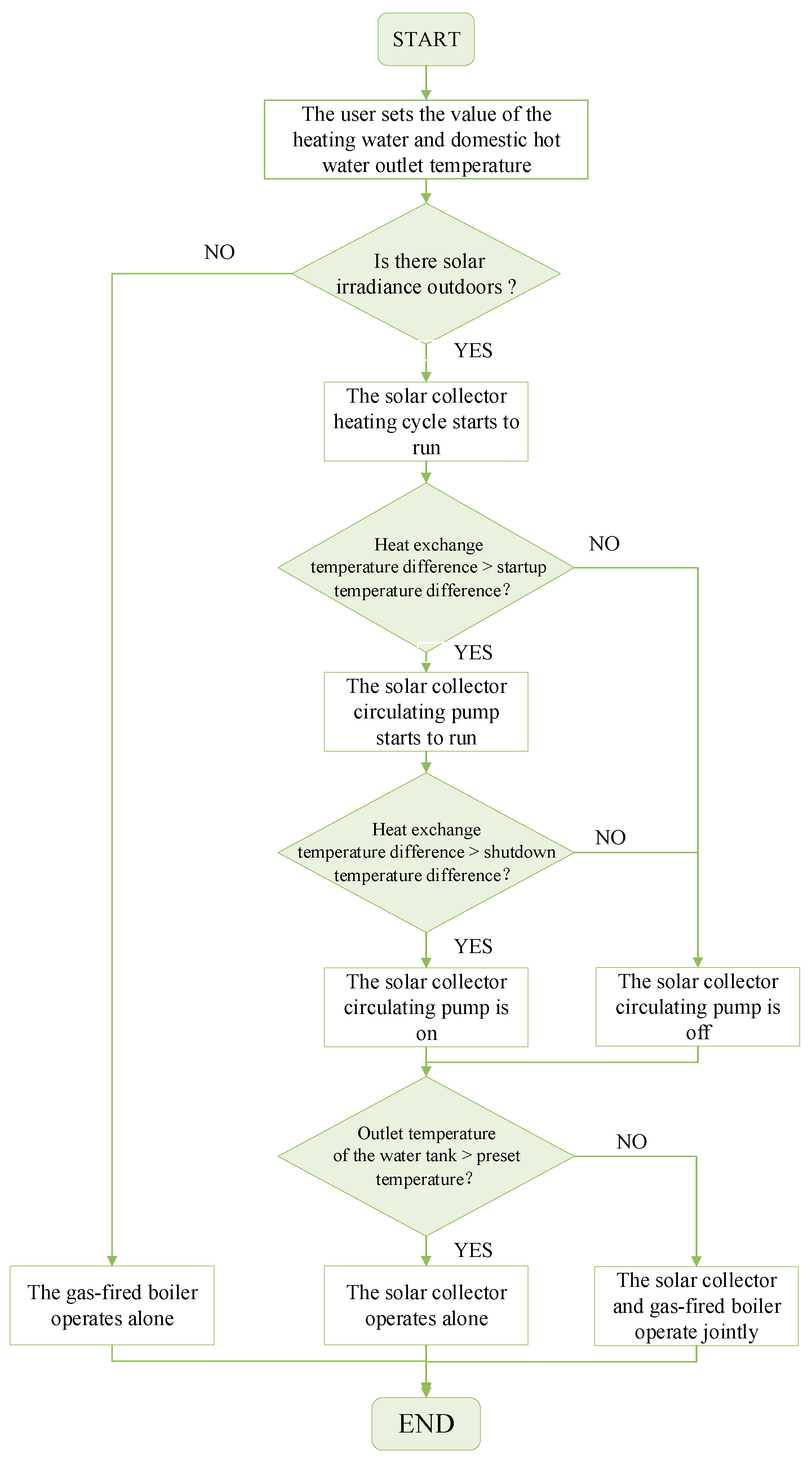
The system has three operating modes: the solar collector operates alone; the solar collector and the gas-fired boiler operate jointly; the gas-fired boiler operates alone. As shown in Figure 2, when the heat provided by solar collector can meet the heat demand of users, the solar collector operates alone, otherwise, the solar collector and the gas-fired boiler operate jointly. When the solar collector cannot be turned on due to the lack of solar irradiance outdoors, the gas-fired boiler operates alone.
The control strategy of the system mainly includes the start-stop control of the solar heat collection cycle. The cycle adopts temperature difference control: set the temperature difference between the temperature of the working fluid entering the heat storage water tank and the temperature of the lower tank. As shown in Figure 2, when the heat exchange difference is greater than the startup temperature difference, the solar collector circulating pump will start; when the difference is less than the shutdown temperature difference, the solar heat collection circulating pump will stop.

2.2. Mathematical Models of the System

An integrated mathematical model is developed for simulating the operation of the system. This model contains models of the flat-plate solar collector, the gas-fired boiler, and the heat storage water tank. The lumped model is adopted for the flat-plate solar collector and the gas-fired boiler, and the stratified model is adopted for the heat storage water tank.

2.2.1. Model of the Flat-Plate Solar Collector

Qt is the heat supplied by flat-plate solar collectors and it can be calculated as follows [37]:
Q t = A I θ η
where A is the area of the solar collector, Iθ is the total solar flux incident on the tilted surface, and η is the thermal efficiency of the flat-plate solar collectors.
The instantaneous efficiency equation is as follows:
η = F R [ ( α ξ ) L p t avg t a I θ ]
where FR is the heat removal factor of the solar collectors; αξ is the absorptance-transmittance product; Lp is the heat loss coefficient of the solar collectors; tavg is the average temperature of the solar collection plate; ta is the ambient temperature.
The thermal performance of the flat-plate solar collector can be tested, and then use the least square method to fit the instantaneous efficiency equation of the collector, so the instantaneous efficiency equation can be obtained as follows:
η = a b ( t avg t a ) I θ
where a and b are constant values that can be obtained by experimental data.
Thus, Qt can be represented as follows:
Q t = A I θ η = a I θ A b A ( t avg t a )

2.2.2. Model of the Gas-Fired Boiler

The heat provided by the gas-fired boiler is determined by the tank temperature Tw, the preset values of the outlet temperature of domestic hot water Ts and heating supply water Tc. The calculation formula of the total heat supplied by the gas-fired boiler Qg is as follows:
Q g = Q gc + Q gs
where Qgc is the heat supplied by the gas-fired boiler to the space heating system and can be calculated as follows:
T c > t g · Q gc = C p m c ( T c t g )
T c t g · Q g c = 0
where Qgs is the heat supplied by the gas-fired boiler to the domestic hot water system and can be estimated as follows:
T s t w 1 · Q gs = C p m c ( T s t g )
T s < t w 1 · Q gs = 0
The thermal efficiency of the gas-fired boiler refers to the ratio of the effective heat obtained by the heated water to the calorific value of gas. The thermal efficiency calculation formula of the gas-fired boiler is as follows:
η g = Q f V g H i × 100 %
where Q f is the heat taken away by heated water; H i is the calorific value of gas; Vg is the gas consumption.
V g = Q gc H i η c + Q gs H i η s
where ηs is the thermal efficiency of the gas-fired boiler when supplying domestic hot water; ηc is thermal efficiency of the gas-fired boiler when supplying heating water.

2.2.3. Model of the Heat Storage Water Tank

This study established different models of the water tank for different usage conditions for more accurate and simple calculation. When there is a demand for domestic hot water, the temperature stratification in the water tank is obvious due to the supplement of cold water at the bottom, so the model of the tank is developed by the stratified model, which divides the water tank into two segments along the vertical direction. The thermal stratification phenomena is not considered when there is no hot water use and the model of the tank is developed by the lumped model.
For reducing the complexity of the mathematical model, assumptions are made as follows:
(1)
The heat dissipation of the heat storage water tank to the surrounding environment is ignored.
(2)
The heat dissipation of the pipeline to the surrounding environment is ignored.
Finite volume formulation is used to analyze the temperature distribution of the tank and the energy balance theory is used to establish thermal equations of the water tank.

The Stratified Model of Heat Storage Water Tank

The schematic of the tank is demonstrated in Figure 3. According to the Figure 3a, the tank is divided into the lower segment (lower node) and the upper segment (upper node), and each segment includes two control bodies of the lower segment of the tank and the heat exchange coil, respectively.
Figure 3c shows the lower node schematic of the tank. The lower part of the tank is heated by solar collectors, and the temperature of the lower tank tw1 rises by obtaining heat from the lower heat exchange coil. Meanwhile, the running water carries the heat from the lower tank to the upper part.
The energy balance equation of the lower node is shown below:
1 2 ρ V C p d t w 1 d τ = Q x + C p m s ( t z t w 1 )
where
Q x = k x A x Δ t mx = C pm m m ( t m 1 t m 2 )
The energy balance equation of the lower coils is shown below:
m m C Pm d t m 1 + t m 2 2 d τ = Q t Q x
Figure 3b shows the upper node schematic of the tank. The upper heat exchange coil performs heat exchange between the storage tank and the heating system, while the running water from the lower part of tank transports heat to the upper part.
The energy balance equation of the upper node is shown below:
1 2 ρ V C p d t w 2 d τ = C p m s ( t w 1 t w 2 ) Q s
where:
t w 2 t h · Q s = k s A s Δ t ms = C p m c ( t g t h )
t w 2 < t h · Q s = 0
The energy balance equation of the upper coils is shown below:
m c C P d t h + t g 2 d τ = Q gc Q c + Q s
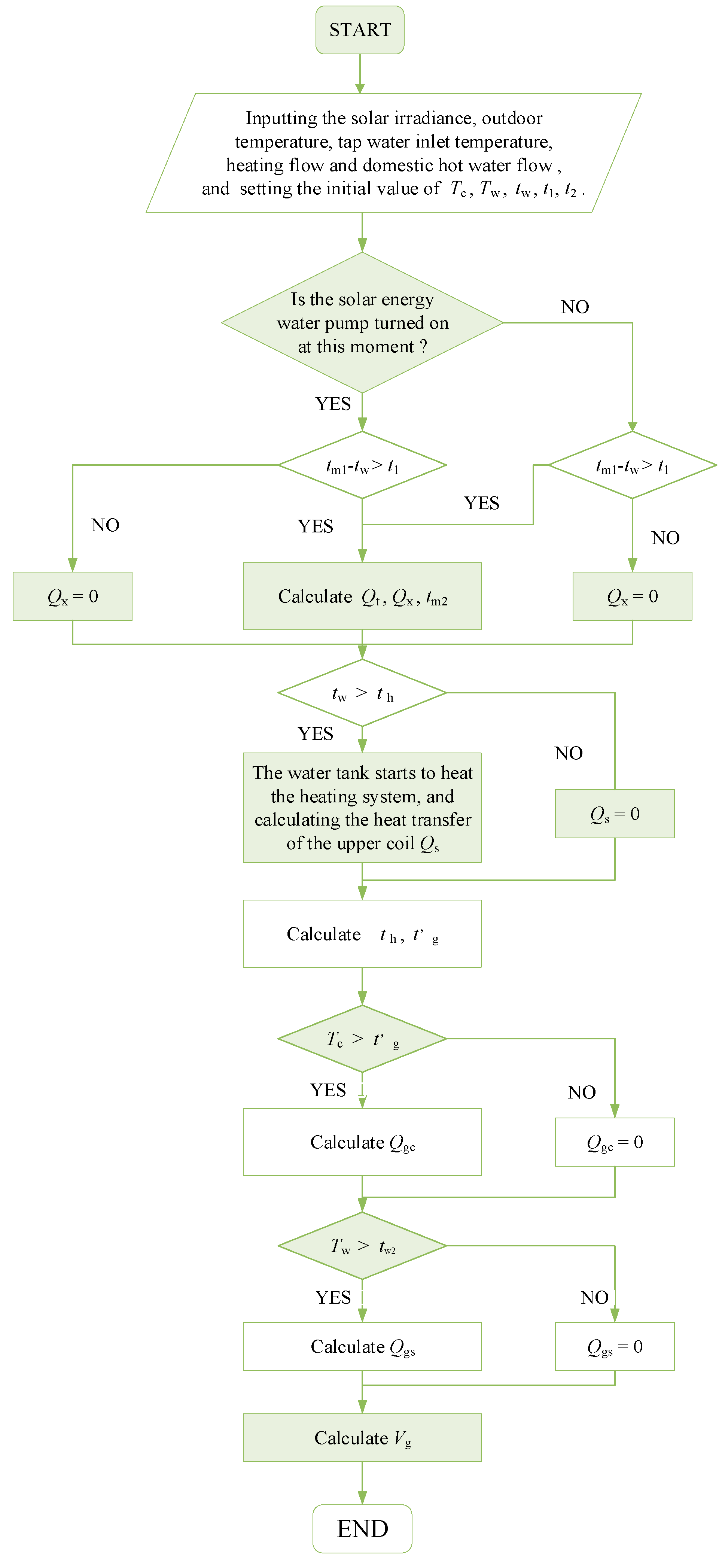
The flowchart is illustrated in Figure 4.

The Lumped Model of the Heat Storage Water Tank

According to Figure 3a, the tank can be divided into three control bodies, which are the water tank, the lower heat exchange coil, and the upper heat exchange coil, respectively. The energy balance equations for the water tank can be represented as follows:
ρ V C P d t w d τ = Q x Q s
where:
t w t h · Q s = k s A s Δ t m s = C P m c ( t g t h )
t w < t h · Q s = 0
The heat supplied by the lower coil Qx can be evaluated as Formula (13). The energy balance equation of the lower coils is shown below:
m m C Pm d ( t m 1 + t m 2 ) / 2 d τ = Q t Q x
The energy balance equation of the upper coils can be represented as Formula (18). The flow chart is shown in Figure 5.

2.2.4. Solution Procedure

The solution procedure of the system is demonstrated in Figure 6. The calculation process can output the results of the heat supply of each unit, the gas consumption of the gas-fired boiler, and the operating cost of the system. At the beginning, inputting the area of the solar collector, the volume of the water tank, startup temperature difference, shutdown temperature difference, and other set values. Then the system calls different modules to calculate according to the difference in the flow of domestic hot water.

3. Experimental Verification

In order to verify the mathematical model, an experimental system was built. Experiments were conducted in Tianjin (latitude = 39°13′ N; longitude = 117°10′ E), a typical city in the cold climate zone of China. During the experiment, the domestic hot water usage was simulated by water release according to the demand in actual situations, and the user’s heating demand was simulated by the cooling water system. Different heating loads were simulated by adjusting the amount of cooling water.

3.1. Experimental System

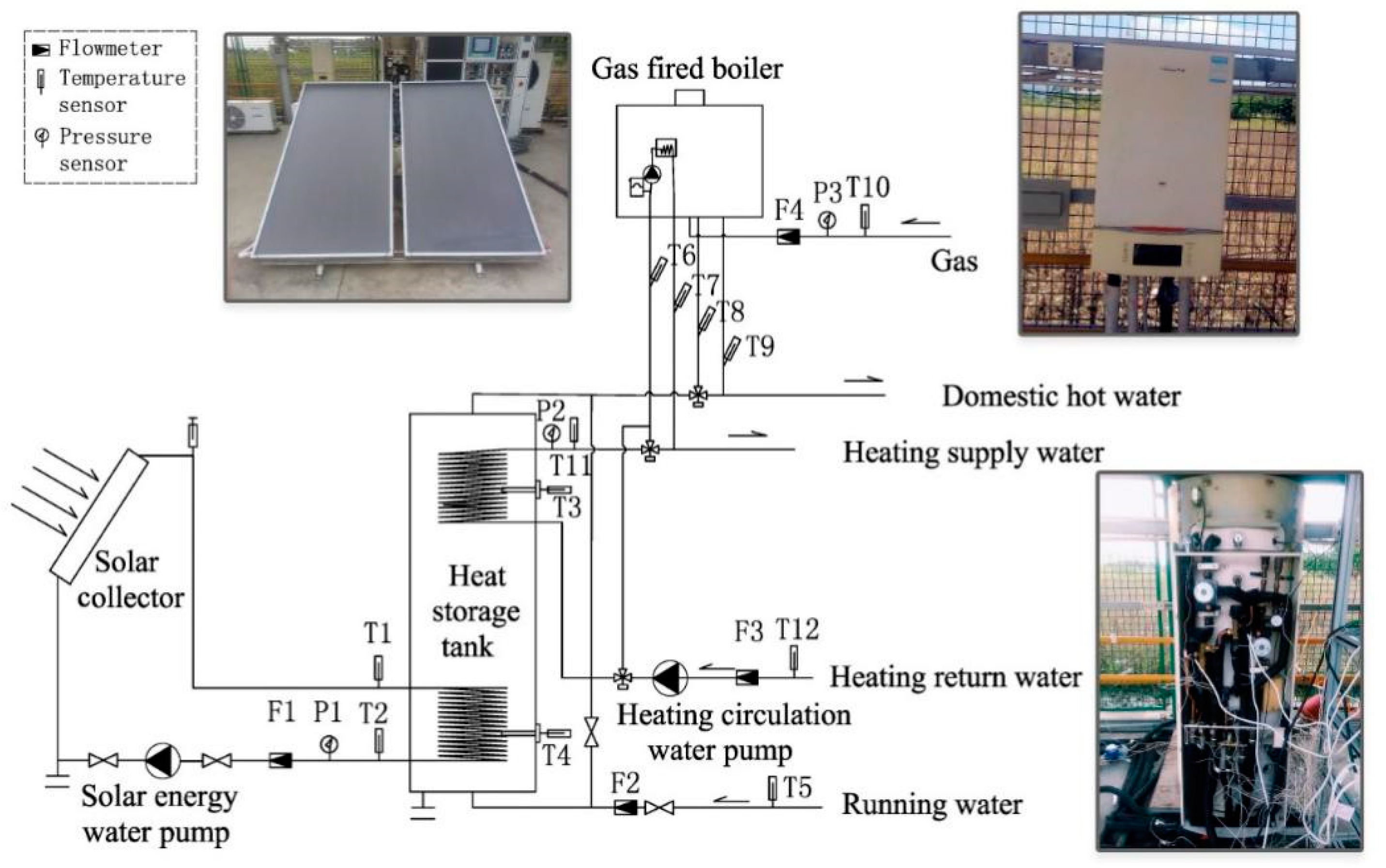
Figure 7 shows the test schematic of the experimental system. Solar collectors faced the south at an inclination angle of 30° in the experiment. During the experiment, the solar collector and the gas-fired boiler operated jointly. The preset temperature of domestic hot water and heating water was 47 °C, the maximum working pressure of heating water was 10.3 MPa, and the working pressure range of domestic water was 0.02–0.6 MPa. The technical parameters of the main system equipment are shown in Table 1.
The main parameters that need to be tested in the experiments are: outdoor environmental parameters, temperature, flow, and pressure. The precision of the test instruments is shown in Table 2.
The heat supplied by the solar collector (Qtt), and gas-fired boiler (Qgt) in this experiment can be calculated as follows [38,39]:
Q tt = i = 1 n C pm m m i ( t m 1 t m 2 ) Δ τ
Q gt = i = 1 n m c i C P ( t g t g ) Δ τ ± i = 1 n m s i C P ( t b 1 t b 2 ) Δ τ
The experimental uncertainty derived from the experiment procedure is estimated by the method provided by Moffat [40] and Kline [41]. It is calculated by the following Equation (25), where y is the derived quantity, x is the measured quantity, and δx is the uncertainty of x. The maximum relative uncertainty of the heat supplied by the solar collector is ±3.21%, and the maximum relative uncertainty of the heat supplied by the gas-fired boiler is ±3.93%.
δ y = ( y x 1 δ x 1 ) 2 + ( y x 2 δ x 2 ) 2 + + ( y x n δ x n ) 2

3.2. Model Validation

Experiments were conducted on August 11 in 2018. The ambient air temperature was in the range of 27.1 °C–34.0 °C. The daily average temperature was 31.2 °C. The solar radiation intensity was in the range of 0–1000 W/m2. The total daily radiation was 15.5 MJ/ m2.
Figure 8a–c shows the comparison between the measured and simulated temperature of the lower tank, the working fluid at the inlet and outlet. The average deviation of the solar working fluid temperature at the inlet was 2.08 °C (4.9%) while the maximum one was 6.61 °C (14.5%). The average deviation of the solar working fluid temperature at outlet was 2.15 °C (5.1%), while the maximum one was 6.55 °C (15.3%). The average deviation of the lower tank’s temperature was 2.18 °C (4.9%) while the maximum one was 4.28 °C (9.7%).
Figure 9a–c shows the comparison between the measured and simulated temperature of the upper tank, the supply heating water from the tank, and the return heating water to the tank. The average deviation of the supply heating water temperature was 0.85 °C (2.0%) while the maximum one was 5.19 °C (12.8%). The average deviation of the return heating water temperature was 1.25 °C (3.1%) while the maximum one was 6.98 °C (19.3%). The average deviation of the upper tank temperature was 1.75 °C (4.4%) while the maximum one was 6.72 °C (16.0%).
The comparison between measured and simulated values of each heating unit are shown in Table 3. The deviation of the heat provided by the solar collectors was 1.24 MJ (6.70%), the deviation of the heat supplied by the gas-fired boiler was 7.45 MJ (6.77%), the deviation of the gas consumed by the gas-fired boiler was 0.31 m3 (5.53%).
Given the necessary assumptions of the mathematic models and error analysis, it indicates that the simulated results exhibit good agreement with the test results, and the model can be used in the following analysis.

4. System Optimization

4.1. Objective Function

Thermal performance and economy are important indicators that determine the promotion and application of the solar–gas systems, so AEER and AC are taken as the objective functions to optimize this system, respectively. AEER shows the rationality of the system for the application of various energy sources. AC shows the economy of the system’s entire life cycle.
The AEER can be calculated as follows [42]:
A E E R = Q t + Q g Q y
The primary energy consumed throughout the year Qy can be calculated as follows:
Q y = 3.6 × 10 6 × ( N τ sol + N g τ g a s ) β b + V g H i
where β b is the power generation efficiency, the value is 0.345.
The AC can be calculated as follows [43]:
A C = C 0 i ( 1 + i ) n ( 1 + i ) n 1 + C y
where i is the discount rate, the value is 4.35%, n is the service life of the equipment, the value is 15 years.
Where C0 is the initial investment and the value can be calculated as follows:
C 0 = C s + C g + C w
where Cy is the annual operating cost and the value can be calculated as follows:
C y = p e · N · t + p g · V g
where pe is the price of electricity, the value is USD 0.078/(kWh), pg is the price of gas, the value is USD 0.376/m3.

4.2. Optimization Design

4.2.1. Heating Demand

A house for four persons with the area of 104.98 m2 located in Tianjin is studied to analyze the performance of the solar energy–gas-fired boiler system. The parameters of the enclosure structure can be seen in Table 4. The system should simultaneously undertake the user’s heating load and domestic hot water load.
(1)
The domestic hot water load: the domestic hot water load Qw can be calculated as follows [44]:
Q w = Z V w ρ C p ( T w t z ) K h
where Vw is the water consumption per capita, Z is the user number, the value is 4, Kh is a proportional parameter, tz is the temperature of tap water. The calculated results are given in Table 5. The calculation result shows that the maximum hot water load is 11,720.80 kW·h.
(2)
The heating load: eQuest [45] software is used to calculate the heating load of the residential room; it can be seen from Figure 10 that the maximum heating load is 8.56 kW.

4.2.2. Equipment Selection

According to the load of the case, the solar energy–gas-fired boiler system is designed. The maximum area of the flat-plate solar collector Amax can be calculated as follows [46]:
A max = 84600 Q f J T ( 1 η L ) η d
where Q is the maximum value of the user’s heating load and domestic hot water load, f is the solar fraction, η d is the average collector efficiency, the value is 0.35, η L is the heat loss efficiency of pipeline and storage tank, the value is 0.25, JT is the average daily radiation of solar collector.
The heat storage tank is the heat storage equipment of the solar heat collection unit and the domestic hot water supply equipment of the user. The equation of the water tank’s volume V is shown below:
V 1.5 V mh
where:
V mh = C h V h
where Ch is the hourly variation coefficient; Vh is the average hourly domestic hot water flow, L.
The maximum heating load in this case is 8.56 kW. According to Equation (31), the maximum solar collector area is 10.1 m2. The average daily hot water consumption per capita is 80 L, and the daily water consumption of the room is 320 L. According to Equation (32), the smallest volume of the heat storage water tank is 120 L. The startup temperature difference of the cycle is in the range of 3 °C–4 °C, the shutdown temperature difference is in the range of 1 °C–2 °C. The traditional equipment in the market is considered, and the specifications of different equipment are shown in Table 6.
According to the standard [46], the conventional combination of this case is as follows: the solar collector area is 10 m2, the heat storage water tank is 200 L, the startup and shutdown temperature differences are 3 °C and 1 °C. The scheme was simulated by the mathematical model to calculate the AC and the AEER of the system. The AC is USD 667.80 and the AEER is 1.223.

4.2.3. Optimization Schemes

The orthogonal experiment design (OED) method is regarded as a modern approach to characterize and optimize system performance in many research areas. The OED method can be used to select representative points from the full factorial experiment in such a way that the points are distributed uniformly within the test range and, thus, can adequately represent the overall situation. The combination of equipment specifications and control strategies are optimized by orthogonal experiment methods for the optimization of the system.
Considering the equipment models (Table 6), the choices of equipment specifications and control strategies are shown below:
Factor A = solar collector area; four levels: 4, 6, 8, 10 m2.
Factor B = water tank volume; three levels: 200, 300, 400 L.
Factor C = startup temperature difference of the solar collector cycle; three levels: 3 °C, 3.5 °C, 4 °C.
Factor D = shutdown temperature difference of the solar collector cycle; three levels: 1 °C, 1.5 °C, 2 °C.
The orthogonal design table was generated using the Statistical Product and Service Solutions (SPSS) software, as listed in Table 7.
The mathematical model was used to simulate the schemes for calculating the heat supplied by each heating unit, gas and power consumption, the AC, and the AEER of the system. The results of each scheme are shown in Table 8. It can be seen that there are different optimal schemes for the two objective functions.
Optimum scheme 1: the optimized result is combination 16 when the AEER is taken as the objective function. The area of solar collectors is 10 m2, the rated power of the gas-fired boiler is 9.4–24.5 kW, the heat storage water tank is 400 L, the startup and shutdown temperature difference are 3.5 °C and 1.0 °C, the AC is USD 657.80 and the AEER is 1.278. Compared with the conventional scheme, the AEER is increased by 4.5%.
Optimum scheme 2: the optimized result is combination 9 when taking the minimum AC of the system is taken as the objective function. The area of solar collectors is 8 m2, the rated power of gas-fired boiler is 9.4–24.5 kW, the heat storage water tank is 200 L, the startup and shutdown temperature difference are 3.5 °C and 1.5 °C, the AC is USD 634.00 and the AEER is 1.240. Compared with the conventional scheme, the AC is reduced by 5.1%.

4.3. Sensitivity Analysis

In order to analyze the influence of different design variables on AEER and AC within the scope of system optimization, the sensitivity coefficient E is introduced for sensitivity analysis [47]. The sensitivity coefficient E is used to measure the relative change of the dependent variable Y caused by the change of the independent variable X, which can be calculated as follows:
E = Δ Y Y / Δ X X

4.3.1. Sensitivity of the AEER

When taking the AEER as the objective function, the solar collector area is 10 m2, the volume of heat storage water tank is 400 L, the rated power of the gas-fired boiler is 26 kW, and the startup and shutdown temperature differences are 3.5 °C and 1.0 °C, respectively.
The AEER is calculated when the area of the solar collector is around 10 m2. The simulation results (in Figure 11) show that the AEER increases with the increase of the solar collector area. When the area of the solar collector increases by 50%, the AEER increases by 3.6%. The elasticity coefficient E is 0.074.
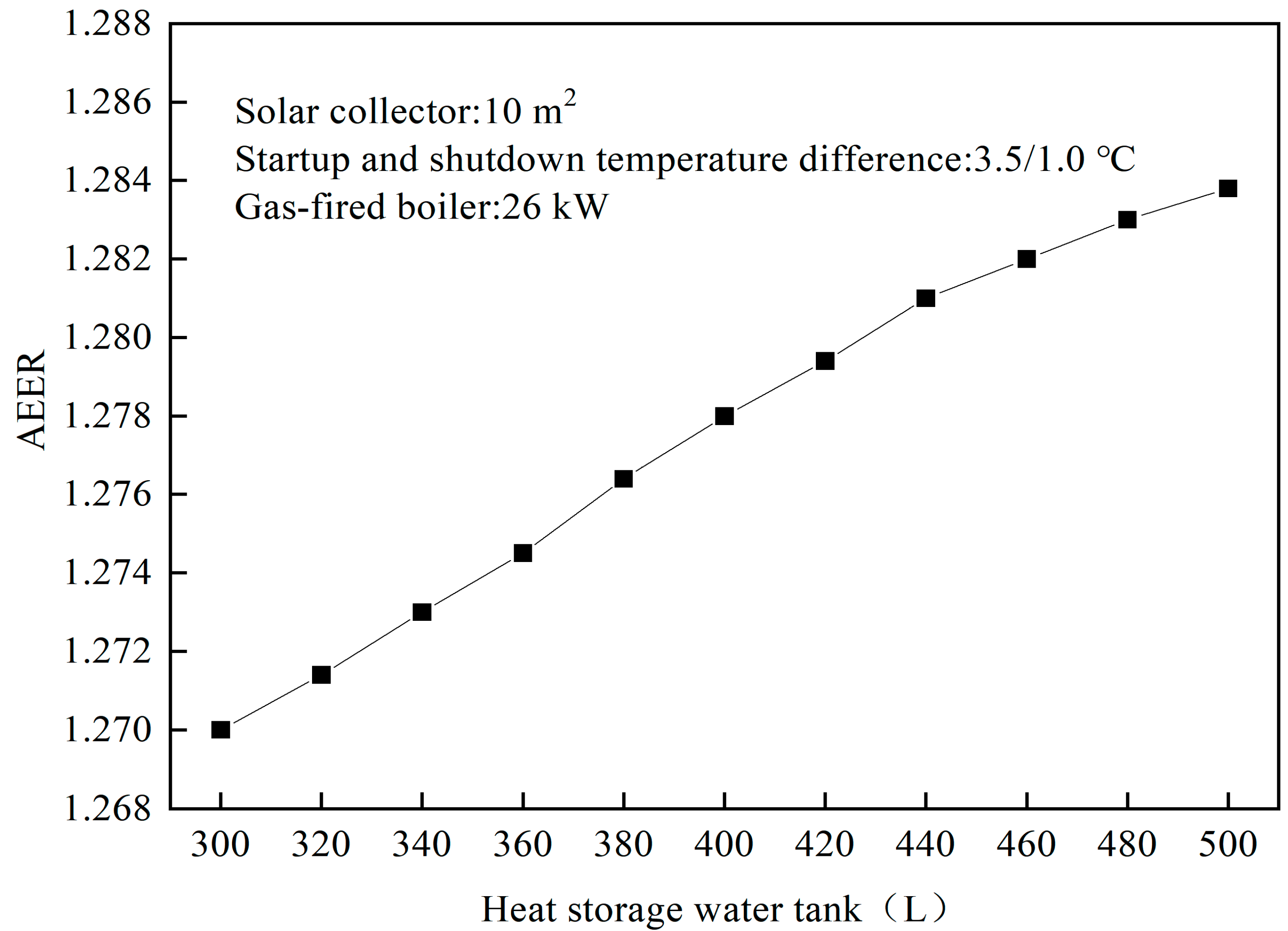
The AEER is calculated when the volume of the heat storage water tank is around 400 L. The simulation results (in Figure 12) show that the AEER increases with the increase of the volume of the heat storage water tank. When the volume of the heat storage water tank increases by 66.7%, the AEER increases by 1.1%. The sensitivity coefficient E is 0.017.
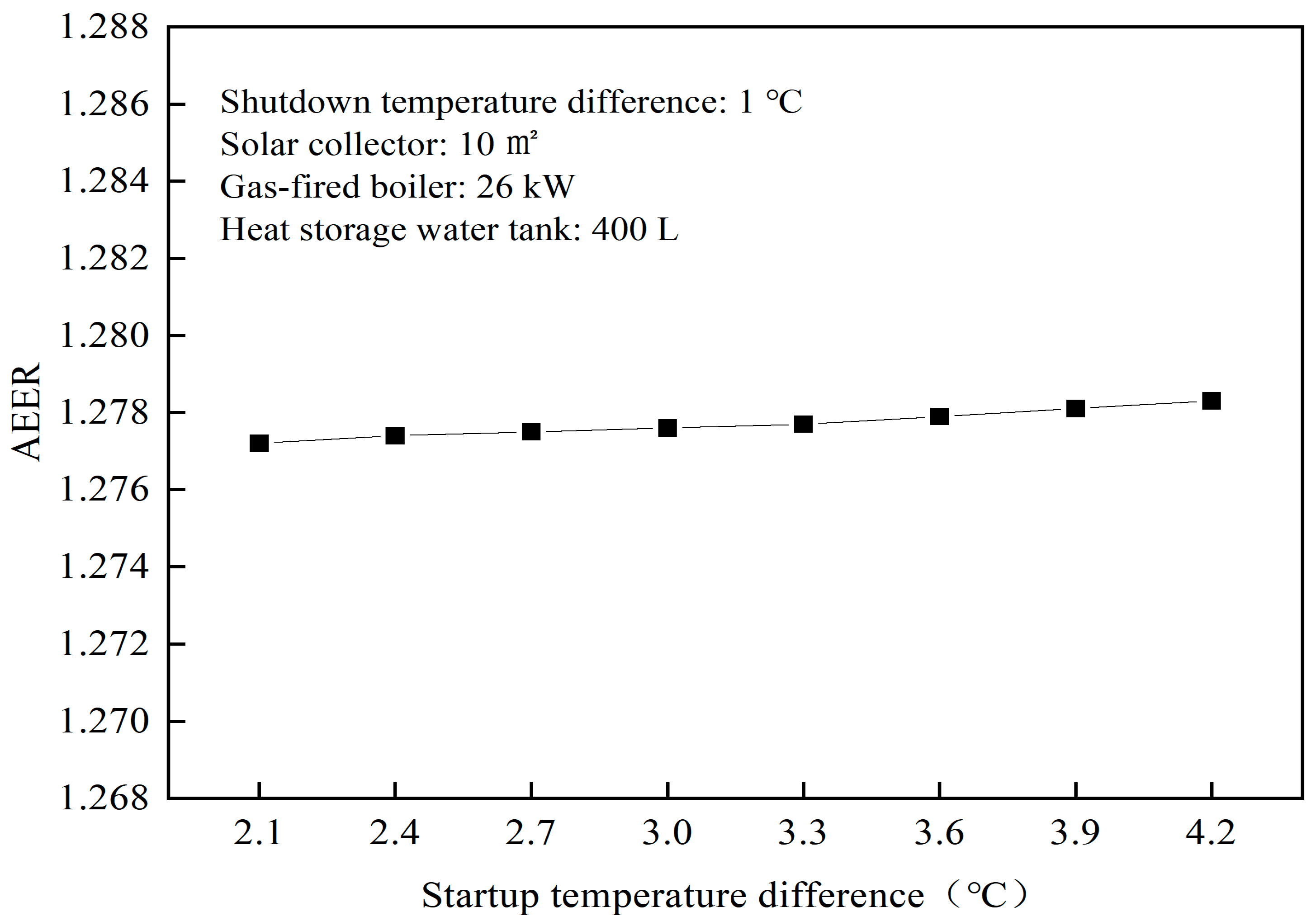
The EER is calculated when the startup temperature difference is around 3.5 °C. The simulation results (in Figure 13) show that the EER slowly grows with the increase of the startup temperature difference. When the startup temperature difference increases by 85%, the EER increases by 0.75%. The sensitivity coefficient E is 0.002.
The AEER is calculated when the shutdown temperature difference is around 1.0 °C. The simulation results (in Figure 14) show that the AEER increases with the increase of the shutdown temperature difference. When the shutdown temperature difference increases by 257%, the AEER increases by 2.8%. The sensitivity coefficient E is 0.003.
The results indicate that the AEER of each design variable to the system is positive feedback. The order of sensitivity is: solar collector area > heat storage water tank volume > shutdown temperature difference > startup temperature difference. Therefore, when building the system, the area of the collector ought to be first considered to the optimal value.

4.3.2. Sensitivity of the Average Annual Cost

When taking the AC of the system as the objective function, the solar collector area is 8 m2, the volume of the heat storage water tank is 200 L, the rated power of the gas-fired boiler is 26 kW, and the startup and shutdown temperature differences are 3.5 °C and 1.5 °C, respectively.
The AC was calculated when the area of the solar collector was around 8 m2. The simulation results (in Figure 15) show that the operating cost of the system is reduced and the initial investment is increased with the increase of the area of solar collectors. The annual cost of the system decreases first and then increases. The results indicate that the optimized area of the solar collector is 7.5 m2, and the minimum AC is USD 633.62.
The AC is calculated when the heat storage water tank volume is around 200 L. The simulation results (in Figure 16) show that the initial investment is increased; the operating cost of the system decreases first and then increases with the increase of the volume of the heat storage water tank. The AC of the system decreases first and then increases. The results indicate that the optimized volume of the heat storage water tank is 160 L, and the minimum AC is USD 632.52.
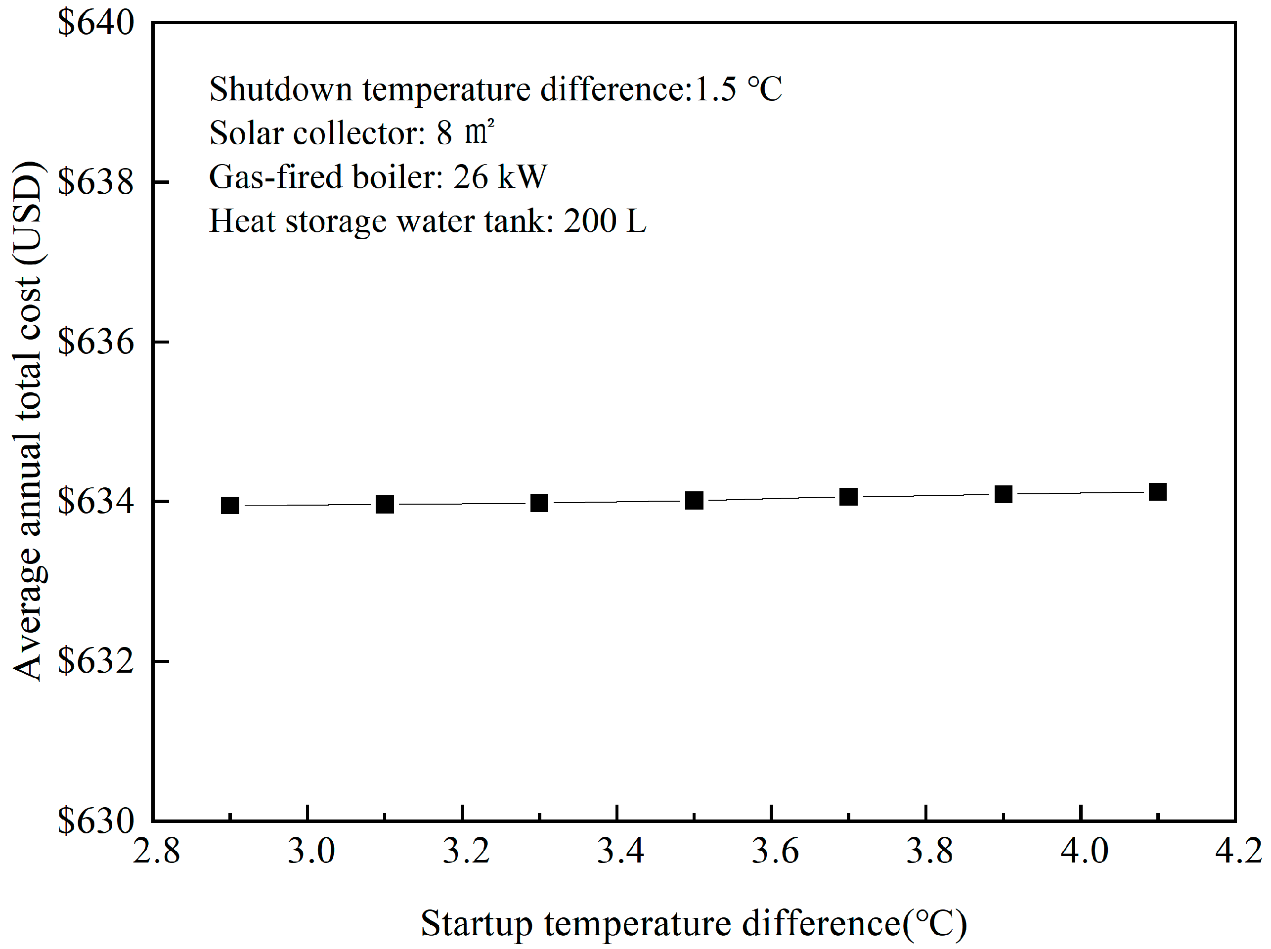
The AC is calculated when the startup temperature difference is around 3.5 °C and the results are shown in Figure 17. The simulation results show that the cost of the system changes little with the increase of the startup temperature difference. The AC is approximately USD 634.00.
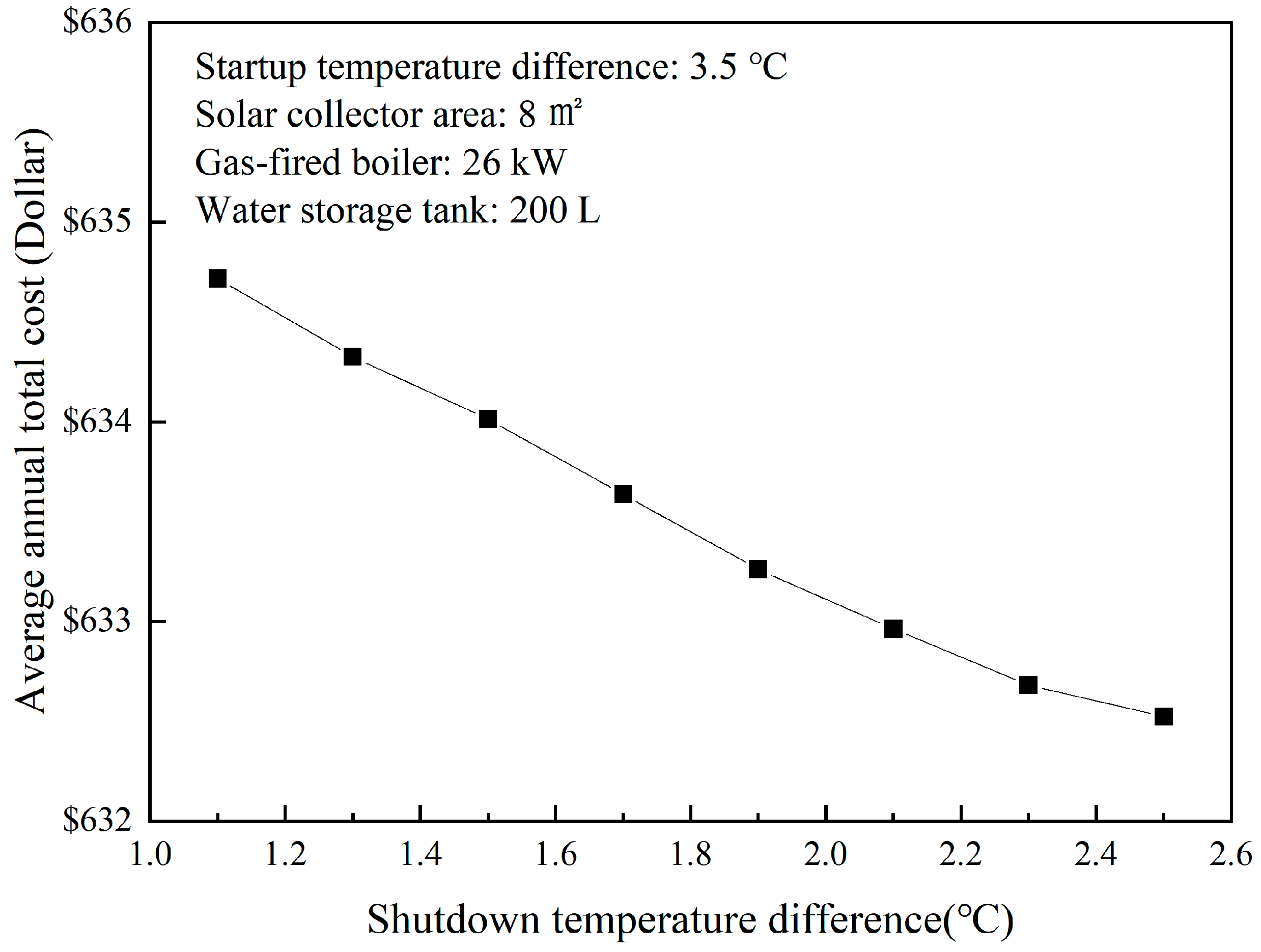
The AC is calculated when the shutdown temperature difference is around 1.5 °C; it can be seen from Figure 18 that the AC decreases with the increase of the shutdown temperature difference. The AC of the system decreases by 0.3% in dollars when the shutdown temperature difference increases by 90%. The sensitivity coefficient E is −0.038.
It can be concluded from the results that the closer the solar collector area and the volume of the heat storage water tank are to the extreme values, the less sensitive they are to the AC of the system. The sensitivity of the shutdown temperature difference is greater than the startup temperature difference.

5. Conclusions

As there are limited studies focusing on the optimization design of the hybrid energy system, this study proposed a holistic method to comprehensively study the different combinations of equipment specifications and control strategies of the system for better efficiency and economics. In this study, a detailed mathematical model of the hybrid energy system was developed and validated by experiments, and it was used to simulate the different operating conditions of the system and to evaluate the optimal design of the cost-effective system. A case study was conducted in Tianjin, China, and the influence of different variables was evaluated by the sensitivity analysis.
The system was optimized by the orthogonal design method. When the AEER is used as the objective function, the optimum scheme is the following: the solar collector area is 10 m2, the volume of the heat storage water tank is 400 L, the rated power of the gas-fired boiler is 24.5 kW, the startup and shutdown temperature differences are 3.5 °C and 1.0 °C, the AEER is 1.278. Moreover, when taking the minimum AC of the system as the objective function, the optimum scheme is that the solar collector area is 8 m2, the rated power of the gas-fired boiler is 24.5 kW, the volume of the heat storage water tank is 200 L, the startup and shutdown temperature differences are 3.5 °C and 1.5 °C, the AC is USD 634.00.
The sensitive ranking of the AEER of each design variable to the system is: solar collector area > heat storage water tank volume > shutdown temperature difference > startup temperature difference. The area of the solar collector and the volume of the heat storage water tank hold extreme value for the AC of the system. The closer they are to the extreme values, the less sensitive they are to the AC of the system.

Author Contributions

Conceptualization, M.T. and Y.Y.; methodology, M.T., H.Z. and T.Y.; software, T.Y.; validation, M.Z.; formal analysis, M.T. and Y.Y.; resources, S.Y. and H.Z.; data curation, M.Z.; writing—original draft preparation, M.T.; writing—review and editing, M.T. and Y.Y.; supervision, S.Y. All authors have read and agreed to the published version of the manuscript.

Funding

This research received no external funding.

Data Availability Statement

The data that support the findings of this study are available from the corresponding author upon reasonable request.

Acknowledgments

This work is accomplished in the National Engineering Laboratory for Digital Construction and Evaluation Technology of Urban Rail Transit.

Conflicts of Interest

The authors declare no conflict of interest.

Nomenclature

a, bconstant value
fsolar fraction
Idiscount rate, %
kx/ksheat transfer coefficient of lower/upper heat exchange coil, W/(m2·K)
mm/mmimass flow rate of solar working fluid, kg/s
ms/msimass flow rate of domestic hot water, kg/s
mc/mcimass flow rate of heating system, kg/s
Nservice life of the equipment
peprice of electricity, USD
pgprice of gas, USD
taambient temperature, °C
tavgaverage temperature of the solar collection plate, °C
tb1/tb2domestic hot water at the inlet/outlet of the gas-fired boiler
t1/t2startup/shutdown temperature difference of the solar thermal cycle, °C
thheating water temperature at the inlet of the heat storage water tank, °C
t g heating water temperature at the outlet of the heat storage water tank, °C
tgheating water temperature at the outlet of the gas-fired boiler, °C
tm1, tm2solar working fluid temperature at the outlet/inlet of the solar collector, °C
twtemperature of the heat storage water tank, °C
tw1, tw2temperature of the lower/upper heat storage water tank, °C
tztap water temperature at the inlet of the heat storage water tank, °C
Aarea of solar collectors, m2
Ax/Asarea of the lower/upper heat exchange coil, m2
C0initial investment, USD
Csinitial investment of solar collectors, USD
Cginitial investment of gas-fired boiler, USD
Cwinitial investment of heat storage water tank, USD
Cyannual operating cost, USD
Chhourly variation coefficient
CPspecific heat capacity of water, J/kg·°C
CPmspecific heat capacity of the solar working fluid, J/kg·°C
FRheat removal factor of solar collectors
Iθtotal solar flux incident on tilted surface, W/m2
JTaverage daily solar radiation of solar collectors, kJ/m2
Hicalorific value of gas, kJ/m3
Khproportional parameter
Lpheat loss coefficient of solar collectors
Npower of the solar energy water pump, W
Ngpower of the gas-fired boiler, W
Qcheating load, W
Qwdomestic hot water load, W
Qfheat taken away by heated water, W
Qgtotal heat supplied by the gas-fired boiler, W
Qgcheat supplied by the gas-fired boiler to the heating system, W
Qgsheat supplied by the gas-fired boiler to the domestic hot water system, W
Qgtheat supplied by the gas-fired boiler in this experiment, W
Qtheat supplied by solar collectors, W
Qttheat supplied by solar collectors in this experiment, W
Qxheat supplied by the lower heat exchange coil, W
Qsheat supplied by the upper heat exchange coil, W
Qyprimary energy consumed by the system throughout the year, W
Tcpreset heating supply water temperature, °C
Twpreset domestic hot water temperature, °C
Vvolume of tank, m3
Vggas consumption, m3
Vmhmaximum hourly domestic hot water flow, kg/s
Vhaverage hourly domestic hot water flow, kg/s
Vwwater consumption per capita, L
Zuser number of domestic hot water
αabsorptance
ξtransmittance
βbpower generation efficiency
ηefficiency of the flat-plate solar collectors
ηdaverage efficiency of solar collectors
ηLheat loss rate of pipeline and storage tank
ηgthermal efficiency of the gas-fired boiler
ηsthermal efficiency of the gas-fired boiler when supplying domestic hot water
ηcthermal efficiency of the gas-fired boiler when supplying heating water
Pdensity of water, kg/m3
Τtime variable, s
τtime of experiment record interval, s
τsolrunning time of the solar collector circulating pump, s
τgasrunning time of the gas-fired boiler, s
τ0system operating time, s
tmslogarithmic mean temperature difference between heating circulating water and the water tank, °C
tmxlogarithmic mean temperature difference between the solar working fluid and the water tank, °C

References

  1. International Energy Agency and the United Nations Environment Programme. 2018 Global Status Report: Towards a Zero-Emission, Efficient and Resilient Buildings and Construction Sector. 2018. Available online: https://www.worldgbc.org/news-media/2018-global-status-report-towards-zero-emission-efficient-and-resilient-buildings-and (accessed on 7 May 2020).
  2. United States Department of Energy (DOE). Buildings Energy Data Book. 2011. Available online: https://catalog.data.gov/dataset/buildings-energy-data-book (accessed on 7 May 2020).
  3. Perera, P. Constraints and Barriers to Deployment of Distributed Energy Systems and Micro Grids in Southern China. Energy Procedia 2016, 103, 201–206. [Google Scholar] [CrossRef]
  4. Yu, Y.; Cheng, J.; You, S.; Ye, T.; Zhang, H.; Fan, M.; Wei, S.; Liu, S. Effect of implementing building energy efficiency labeling in China: A case study in Shanghai. Energy Policy 2019, 133, 110898. [Google Scholar] [CrossRef]
  5. Choi, H.J.; Kim, B.S.; Kang, D.; Kim, K.C. Defrosting method adopting dual hot gas bypass for an air-to-air heat pump. Appl. Energy 2011, 88, 4544–4555. [Google Scholar]
  6. Shahsavari, A.; Akbari, M. Potential of solar energy in developing countries for reducing energy-related emissions. Renew. Sustain. Energy Rev. 2018, 90, 275–291. [Google Scholar] [CrossRef]
  7. Obstawski, P.; Tomasz Bakoń, T.; Czekalski, D. Modification of the solar heating system diagnostic method under operating conditions. Appl. Therm. Eng. 2019, 165, 114474. [Google Scholar] [CrossRef]
  8. Huang, J.; Fan, J.; Furbo, S.; Chen, D.; Dai, Y.; Kong, W. Economic analysis and optimization of household solar heating technologies and systems. Sustain. Energy Technol. Assess. 2019, 36, 100532. [Google Scholar] [CrossRef]
  9. Fan, M.; Liang, H.; You, S.; Zhang, H.; Yin, B.; Wu, X. Applicability analysis of the solar heating system with parabolic trough solar collectors in different regions of China. Appl. Energy 2018, 221, 100–111. [Google Scholar] [CrossRef]
  10. Olia, H.; Torabi, M.; Bahiraei, M.; Ahmadi, M.H.; Goodarzi, M.; Safaei, M.R. Application of Nanofluids in Thermal Performance Enhancement of Parabolic Trough Solar Collector: State-of-the-Art. Appl. Sci. 2019, 9, 463. [Google Scholar] [CrossRef] [Green Version]
  11. Peng, Y.; Zahedidastjerdi, A.; Abdollahi, A.; Amindoust, A.; Bahrami, M.; Karimipour, A.; Goodarzi, M. Investigation of energy performance in a U-shaped evacuated solar tube collector using oxide added nanoparticles through the emitter, absorber and transmittal environments via discrete ordinates radiation method. J. Therm. Anal. Calorim. 2020, 139, 2623–2631. [Google Scholar] [CrossRef]
  12. Sarafraz, M.M.; Tlili, I.; Tian, Z.; Bakouri, M.; Safaei, M.R.; Goodarzi, M. Thermal Evaluation of Graphene Nanoplatelets Nanofluid in a Fast-Responding HP with the Potential Use in Solar Systems in Smart Cities. Appl. Sci. 2019, 9, 2101. [Google Scholar] [CrossRef] [Green Version]
  13. Ding, D.; He, W.; Liu, C. Mathematical Modeling and Optimization of Vanadium-Titanium Black Ceramic Solar Collectors. Energies 2021, 14, 618. [Google Scholar] [CrossRef]
  14. Kuczynski, W.; Kaminski, K.; Znaczko, P.; Chamier-Gliszczynski, N.; Piatkowski, P. On the Correlation between the Geometrical Features and Thermal Efficiency of Flat-Plate Solar Collectors. Energies 2021, 14, 261. [Google Scholar] [CrossRef]
  15. Devanarayanan, K.; Murugavel, K.K. Integrated collector storage solar water heater with compound parabolic concentrator—development and progress. Renew. Sustain. Energy Rev. 2014, 39, 51–64. [Google Scholar] [CrossRef]
  16. Zheng, X.; Shi, R.; Wang, Y.; You, S.; Zhang, H.; Xia, J.; Wei, S. Mathematical modeling and performance analysis of an integrated solar heating and cooling system driven by parabolic trough collector and double-effect absorption chiller. Energy Build. 2019, 202, 109400. [Google Scholar] [CrossRef]
  17. Chen, C.; Duan, S.; Cai, T.; Liu, B.; Hu, G. Smart energy management system for optimal microgrid economic operation. IET Renew. Power Gener. 2011, 5, 258–267. [Google Scholar] [CrossRef]
  18. Dou, C.; Liu, B. Transient control for micro-grid with multiple distributed generations based on hybrid system theory. Int. J. Electr. Power Energy Syst. 2012, 42, 408–417. [Google Scholar] [CrossRef]
  19. Qu, S.; Han, J.; Sun, Z.; Yin, R.; Ji, R.; Chai, C. Study of operational strategies for a hybrid solar-geothermal heat pump system. Build. Simul. 2019, 12, 697–710. [Google Scholar] [CrossRef]
  20. Song, A.; Zhu, J.; Zhang, P.; Chang, N.; Cui, Z. Experimental Research on Solar and Geothermal Energy Coupling Power Generation System—ScienceDirect. Energy Procedia 2019, 158, 5982–5987. [Google Scholar] [CrossRef]
  21. Zhao, Y.; Hong, H.; Jin, H. Optimization of the solar field size for the solar–coal hybrid system. Appl. Energy 2017, 185 Pt 2, 1162–1172. [Google Scholar] [CrossRef]
  22. Bartha, S.; Vajda, B. Modelling and Simulation of the Solar—Biomass Base Heating System for Low Energy Buildings Developed for Rural Area. In Conference on Sustainable Energy; Springer: Cham, Switzerland, 2017. [Google Scholar]
  23. Babrekar, V.J.; Khandalkar, M.A.G.; Ghurde, M.S.P. Hybrid Power Generation System Using Wind Energy and Solar Energy. 2017. Available online: https://www.researchtrend.net (accessed on 26 April 2020).
  24. Rovense, F.; Reyes-Belmonte, M.Á.; Romero, M.; González-Aguilar, J. Combined heat/cooling and power generation using hybrid micro gas turbine in a CST plant for a residential off-grid application. In AIP Conference Proceedings; AIP Publishing LLC: Daegu, Korea, 2020. [Google Scholar]
  25. Terhan, M.; Kemal, C. Energy and exergy analyses of natural gas-fired boilers in a district heating system. Appl. Therm. Eng. 2017, 121, 380–387. [Google Scholar] [CrossRef]
  26. Sun, F.; Zhao, X.; Chen, X.; Fu, L.; Liu, L. New configurations of district heating system based on natural gas and deep geothermal energy for higher energy efficiency in northern China. Appl. Therm. Eng. 2019, 151, 439–450. [Google Scholar] [CrossRef]
  27. Voss, K. Solar energy in building renovation—Results and experience of international demonstration buildings. Energy Build. 2000, 32, 291–302. [Google Scholar] [CrossRef]
  28. Fischer, S.; Heidemann, W.; Müller-Steinhagen, H.; Perers, B.; Bergquist, P.; Hellström, B. Collector test method under quasi-dynamic conditions according to the European Standard EN 12975-2. Sol. Energy 2004, 76, 117–123. [Google Scholar] [CrossRef]
  29. Hang, Y.; Qu, M.; Zhao, F. Economic and environmental life cycle analysis of solar hot water systems in the United States. Energy Build. 2012, 45, 181–188. [Google Scholar] [CrossRef]
  30. Karki, S.; Haapala, K.R.; Fronk, B.M. Investigation of the combined efficiency of a solar/gas hybrid water heating system. Appl. Therm. Eng. 2019, 149, 1035–1043. [Google Scholar] [CrossRef]
  31. Mehmood, A.; Waqas, A.; Said, Z.; Rahman, S.M.; Akram, M. Performance evaluation of solar water heating system with heat pipe evacuated tubes provided with natural gas backup. Energy Rep. 2019, 5, 1432–1444. [Google Scholar] [CrossRef]
  32. Cheng, L.; Guo, B.; Li, K. Design and Optimization of a Hybrid Energy System for Decentralized Heating. Fluid Dyn. Mater. Process. 2021, 17, 49–70. [Google Scholar] [CrossRef]
  33. Kou, G.X.; Cai, L.L.; Ye, Y.J.; Lu, R.R.; Shang, P.N. Case analysis of the solar heating system assisted by condensing wall-mounted gas heater. Appl. Mech. Mater. 2014, 672–674, 7–12. [Google Scholar] [CrossRef]
  34. Yu, S.; Xu, Y.; Shao, Y.; Yu, Z.; Feng, G. Research on solar-natural gas combined heating technology in cold and severe cold zone. Procedia Eng. 2017, 205, 2318–2324. [Google Scholar] [CrossRef]
  35. Chen, Z.; Qin, C.; Dai, W.; Lu, H. Analysis of a hybrid water supplying system with solar collector and fuel gas. Acta Energ. Sol. Sin. 2011, 11, 1652–1656. [Google Scholar]
  36. Zhou, H.; Li, G. Economic Analysis of the Combined Heating System of Solar Collector and Gas Boiler. IOP Conf. Ser. Earth Environ. Sci. 2020, 545, 012021. [Google Scholar] [CrossRef]
  37. Santos, B.M.; Queiroz, M.R.; Borges, T. A solar collector design procedure for crop drying. Braz. J. Chem. Eng. 2005, 22, 277–284. [Google Scholar] [CrossRef] [Green Version]
  38. General Administration of Quality Supervision, Inspection and Quarantine of the People’s Republic of China, National Standardization Administration of China. GB/T 4271-2007 Test Methods for the Thermal Performance of Solar Collectors; China Standard Press: Beijing, China, 2008. [Google Scholar]
  39. General Administration of Quality Supervision, Inspection and Quarantine of the People’s Republic of China, National Standardization Administration of China. GB/T 20665-2015 Minimum Allowable Values of Energy Efficiency and Energy Efficiency Grades for Domestic Gas Instantaneous Water Heater and Gas Fired Heating and Hot Water Combiboilers; China Quality Inspection Press: Beijing, China, 2014. [Google Scholar]
  40. Moffat, R.J. Describing the uncertainties in experimental results. Exp. Therm. Fluid Sci. 1988, 1, 3–17. [Google Scholar] [CrossRef] [Green Version]
  41. Kline, S.J.; McClintock, F.A. Describing Uncertainty in Single-Sample Experiments. Mech. Eng. 1953, 75, 3–8. [Google Scholar]
  42. Baglivo, C.; Bonuso, S.; Congedo, P. Performance Analysis of Air Cooled Heat Pump Coupled with Horizontal Air Ground Heat Exchanger in the Mediterranean Climate. Energies 2018, 11, 2704. [Google Scholar] [CrossRef] [Green Version]
  43. Shafiee, M.; Alghamdi, A.; Sansom, C.; Hart, P.; Encinas-Oropesa, A. A Through-Life Cost Analysis Model to Support Investment Decision-Making in Concentrated Solar Power Projects. Energies 2020, 13, 1553. [Google Scholar] [CrossRef] [Green Version]
  44. Ministry of Housing and Urban-Rural Development of the People’s Republic of China. GB 50015-2019 Building Water Supply and Drainage Design Code; China Planning Press: Beijing, China, 2019. [Google Scholar]
  45. eQUEST. The Quick Energy Simulation Tool. Available online: https://doe2.com/equest/index.html (accessed on 13 May 2021).
  46. Zheng, R.; Lu, B.; Li, Z. Technical Handle Book for Solar Heating; Architecture & Building Press: Beijing, China, 2012; pp. 135–137. [Google Scholar]
  47. Hamby, D.M. A review of techniques for parameter sensitivity analysis of environmental models. Environ. Monit. Assess. 1994, 32, 135–154. [Google Scholar] [CrossRef]
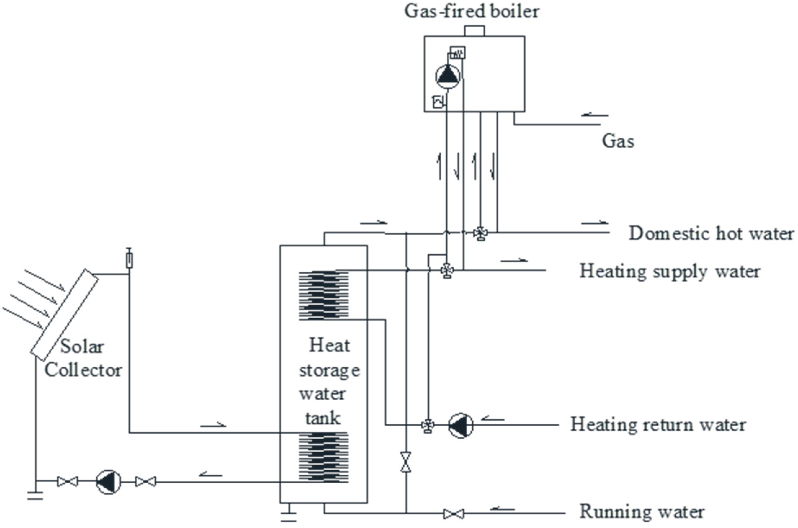
Figure 1. Schematic of the solar energy-gas-fired boiler system.
Energies 14 03195 g001
Figure 2. Flowchart of the operation modes and control strategies.
Energies 14 03195 g002
Figure 3. The schematic of the tank.
Energies 14 03195 g003
Figure 4. Flowchart of the stratified model.
Energies 14 03195 g004
Figure 5. Flowchart of the lumped parameter model.
Energies 14 03195 g005
Figure 6. The solution procedure of the system.
Energies 14 03195 g006
Figure 7. The test schematic of the solar energy–gas boiler system.
Energies 14 03195 g007
Figure 8. Comparison of the measured and simulated temperature of the lower tank: (a) temperature of the lower tank, (b) temperature of solar working fluid inlet, and (c) temperature of solar working fluid outlet.
Energies 14 03195 g008aEnergies 14 03195 g008b
Figure 9. Comparison of the measured and simulated temperature of the upper tank: (a) temperature of the upper tank, (b) temperature of the heating supply water, and (c) temperature of the heating return water.
Energies 14 03195 g009
Figure 10. Heating load in Tianjin.
Energies 14 03195 g010
Figure 11. The relationship between the AEER and the solar collector area.
Energies 14 03195 g011
Figure 12. The relationship between the AEER and the heat storage water tank volume.
Energies 14 03195 g012
Figure 13. The relationship between the AEER and the startup temperature.
Energies 14 03195 g013
Figure 14. The relationship between the AEER and the shutdown temperature.
Energies 14 03195 g014
Figure 15. The relationship between the AC and the solar collector area.
Energies 14 03195 g015
Figure 16. The relationship between the AC and the heat storage water tank volume.
Energies 14 03195 g016
Figure 17. The relationship between the AC and the startup temperature.
Energies 14 03195 g017
Figure 18. The relationship between the AC value and the shutdown temperature.
Energies 14 03195 g018
Table 1. Technical parameters of system equipment.
EquipmentTechnical Parameters
Solar collectorEquipment model: F-L/0.8-G/TL-1.8-ZT/K-A2
Area: 3.6 m2
Placement: oriented to the south at a tilt angle of 30° outside
Solar cycle working fluidDensity: 1.14 kg/L Specific heat capacity: 3.5 kJ/(kg·K)
Gas-fired boilerEquipment model: L1PB20-Y36BL, Rated heating capacity: 20 KW
Heat storage water tankEquipment model: SQT300 Size: 300 L
Upper coils size: Φ25 × 6100 mm
Lower coils size: Φ25 × 3920 mm
Table 2. The precision of instruments.
Instrument NameRangePrecision
Electromagnetic flow meter0.14–0.6 m3/h±0.5%
Turbine flow meter0.14–0.36 m3/h±0.5%
Wet gas meter0.04–6 m3/h±0.5%
Pt100 thermometer0–120 °C±0.1 °C
Y-100 pressure gauge0–6 KPa±2.5%
Solar radiometric instrumentation0–2000 W/ m2±15%
Table 3. Measured and simulated values of each unit.
Performance FactorMeasured ValueSimulated ValueDeviation%
The heat supplied by solar collectors (MJ)18.2817.041.246.70
The heat supplied
by the gas-fired boiler (MJ)
166.68178.787.456.77
The gas consumed by the gas-fired boiler (m3)5.295.600.315.53
Table 4. The parameters of enclosure structure.
Enclosure StructureHeat Transfer Coefficient/(W/m2·K)SizeQuantity
Wall0.44Height 3.01 m-
Windows2.41.8 m × 1.5 mNorth: 2; East and West: 1
Door3.021.8 m × 2.5 mSouth: 1
Table 5. Value of Kh and QW.
TimeKh/%QW/kW·h
7:0052344.16
8:0052344.16
11:0052344.16
13:0052344.16
15:00157032.48
16:00157032.48
17:002511720.80
18:002511720.80
Table 6. The specifications of different equipment.
EquipmentSpecificationsUnit Price (USD)
Gas-fired boiler9.4–19.5 kW862
9.4–20.5 kW940
9.4–23.5 kW1019
9.4–24.5 kW1097
9.4–26.5 kW1175
Tank101–200 L235
201–300 L313
301–400 L392
Flat plate solar heat collector1 m263
Table 7. The results of the orthogonal design.
CombinationSolar Collector
(m2)
Tank
(L)
Startup Temperature
Difference(°C)
Shutdown Temperature
Difference (°C)
142003.01.0
242003.02.0
343003.51.0
444004.01.5
562003.52.0
662004.01.0
763003.01.5
864003.01.0
982003.51.5
1082004.01.0
1183003.01.0
1284003.02.0
13102004.01.5
14102003.01.5
15103004.02.0
16104003.51.0
Table 8. The schemes and results.
CombinationThe Thermal Energy
Provided by Solar (MJ)
The Thermal Energy
Provided by Gas (MJ)
Gas
Consumption (m3)
Power
Consumption (kW·h)
AC
(USD)
AEER
16608.2949,062.421290.00162.70651.0 1.160
26571.5349,097.091290.92132.97649.0 1.167
36769.5149,620.371304.67167.71664.1 1.161
46803.0250,069.561316.48150.94674.5 1.165
58454.3047,119.631238.90135.29641.2 1.212
68501.3347,076.711237.79162.19642.9 1.205
78882.7947,508.091249.13160.40647.0 1.213
89106.3847,895.271259.32177.43659.4 1.212
99688.5445,847.831205.48148.67634.0 1.240
109714.7445,817.821204.69162.35642.0 1.236
1110,341.1446,050.661210.81177.80645.5 1.245
1210,645.3446,428.721220.76157.45654.91.256
1310,557.1344,947.301181.80163.56637.81.258
1410,524.1744,978.001182.61149.63637.11.262
1510,601.2745,194.891181.80149.50646.41.276
1611,729.9245,372.191192.98180.50657.81.278
Publisher’s Note: MDPI stays neutral with regard to jurisdictional claims in published maps and institutional affiliations.