Review

Application of LCA to Determine Environmental Impact of Concentrated Photovoltaic Solar Panels—State-of-the-Art

by
Aleksandra Ziemińska-Stolarska
1,*,
Monika Pietrzak
2 and
Ireneusz Zbiciński
1
1
Faculty of Process and Environmental Engineering, Lodz University of Technology, Wolczanska 213, 90-924 Lodz, Poland
2
Faculty of Chemistry, Lodz University of Technology, Zeromskiego 116, 90-924 Lodz, Poland
*
Author to whom correspondence should be addressed.
Energies 2021, 14(11), 3143; https://doi.org/10.3390/en14113143
Submission received: 21 April 2021 / Revised: 18 May 2021 / Accepted: 24 May 2021 / Published: 27 May 2021
(This article belongs to the Section A2: Solar Energy and Photovoltaic Systems)

Abstract

:
Photovoltaic systems represent a leading part of the market in the renewable energies sector. Contemporary technology offers possibilities to improve systems converting sun energy, especially for the efficiency of modules. The paper focuses on current concentrated photovoltaic (CPV) technologies, presenting data for solar cells and modules working under lab conditions as well as in a real environment. In this paper, we consider up-to-date solutions for two types of concentrating photovoltaic systems: high-concentration photovoltaics (HCPV) and low-concentration photovoltaics (LCPV). The current status of CPV solar modules was complemented by the preliminary results of new hybrid photovoltaic technology achieving records in efficiency. Compared to traditional Si-PV panels, CPV modules achieve greater conversion efficiency as a result of the concentrator optics applied. Specific CPV technologies were described in terms of efficiency, new approaches of a multijunction solar cell, a tracking system, and durability. The results of the analysis prove intensive development in the field of CPV modules and the potential of achieving record system efficiency. The paper also presents methods for the determination of the environmental impact of CPV during the entire life cycle by life cycle assessment (LCA) analysis and possible waste management scenarios. Environmental performance is generally assessed based on standard indicators, such as energy payback time, CO2 footprint, or GHG emission.

Graphical Abstract

1. Introduction

The limited resources of fossil fuels and the increasing consumption of energy are not compatible. To meet the growing needs of the world, the global energy supply system must be transformed [1,2]. In today’s society, renewable sources are becoming more and more common in the energy market. Although the reduction of environmental pollution is a key driver, energy transition brings a wide range of other benefits (e.g., health, economic, and technological) [3,4]. The potential of solar energy is effectively used in photovoltaic (PV) technology at present, where solar radiation is directly converted into electricity. The second type of solar power system is the generation of electricity in an indirect way, by first converting solar energy into heat. In this technology, referring to concentrated solar power (CSP), sunlight focused on optical collectors is the origin of heat that drives an electrical power generator [5,6]. To eliminate disadvantages and highlight the advantages of solar power systems, concentrated photovoltaic (CPV) as a hybrid technology has been developed [7]. In comparison to conventional PV systems, the CPV is still a young and small player in the market for solar electricity generation, with a relatively small number of research works and operating installations [2]. CPV systems improve the utilization and efficiency of solar energy, close to 40% [8], which previous systems could not provide. Additionally, CPV enables cost savings by replacing expensive materials used in classical PV systems with affordable mirrors or lenses [9].
The environmental aspect is one of the crucial challenges of solar energy management. Although photovoltaic technology is considered to be an environmentally friendly technology, a growing number of solar panels at the end-of-life stage raises concerns about further accumulation as waste [10]. Following a report published by the International Renewable Energy Agency (IRENA), the volume of PV panel waste could globally yield a value of up to 60–78 million tons by 2050 [11]. Therefore, the goal is to strive for technology to minimize the environmental impact of the product in all phases of its life cycle, and, in particular, in the phases in which this impact is the greatest. Life cycle assessment (LCA) is now a standardized tool to evaluate the environmental impact of photovoltaic technologies from the cradle to the grave [12,13]. The process of performing LCA is described in two international standards: ISO 14040 [14] and ISO 14044 [15]. According to the norms, the following steps of LCA are referred to: goal definition and scoping, inventory analysis, impact assessment, and interpretation of the results [16]. An important step is to collect the input and output data that are included in the life cycle inventory (LCI). The inventory analysis is a step determining the accuracy of LCA, where all the material and energy flows, as well as all the waste released into the environment over the entire life cycle, are identified and quantified. Most data should be collected from manufacturers to ensure reliable results, but available databases and expert estimates are also frequently used [17]. The environmental profile of a solar module is a result of LCA, which enables the assessment and comparison of different technologies. LCA enables quantitative results to be expressed as different indicators, such as energy payback time (EPBT) or greenhouse gas emission [18]. Most of the LCA analysis deals with conventional flat-plate PV, e.g., [10]; however, due to the rapid development of concentrated photovoltaic technology, the environmental impact of CPV technologies has become an extensively studied topic.
The paper presents the current state of CPV technologies working under real and laboratory testing conditions, highlighting their market value and environmental impact of individual technologies based on the LCA methodology.

2. Historical Perspective and Development of the CPV Technology

The key principle of CPV is the use of cost-efficient concentrating optics that significantly reduce the cell area, allowing for the use of more expensive, high-efficiency cells and potentially a levelized cost of electricity (LCOE) competitive with standard flat-plate PV technology in certain sunny areas with high direct normal irradiance (DNI) [19]. CPV is of most interest in power generation in sun-rich regions with DNI values of more than 2000 kWh/(m2a). The systems are differentiated according to the concentration factor of the technology configuration. Two broad segments of CPV, differentiated by the concentration factor: low-concentration PV (LCPV) with a concentration factor to 30–40 and high-concentration PV (HCPV), where concentration is greater than 300 [8,20]. The LCPV designs use silicon or thin-film PV cell approaches and linear concentrating optics with one-axis tracking. The latter requires higher efficiency and is more expensive despite using the same multijunction cells, which might need cooling during operation. The HCPV takes advantage of the two-axis sun tracking system. The price and efficiency have been the main driving force for developing technical approaches of CPV over the past years. The origins date back to the 1960s when Eugene L. Ralph published the concept of concentrated sunlight and demonstrated conical reflectors onto Si cells [21]. The first lens-based system was presented by Sandia National Laboratory [22]. Based on this project, the Martin Marietta Corporation installed the Fresnel-lens CPV system in Saudi Arabia (350 kW) and Arizona (225 kW) [23]. To address a need for an appropriate solar cell compatible with concentrating optics, the advanced Si and then multijunction solar cells (MJSC) were developed. First, two-junction solar cells were deployed (e.g., GaInP/GaAs), and then they became the basis for the modern three-junction cell (GaInP/GaAs/Ge). In 2001, Amonix (now Arzon Solar) installed the first commercial HCPV at the Glendale Airport in Arizona [8]. One of the first concentrator module technologies was the FLATCON® developed by the Ioffe Institute in Saint Petersburg and Fraunhofer Institute in Freiburg (Germany) [24]. In the FLATCON® technology, the solar radiation is concentrated by silicone-on-glass (SoG) Fresnel lenses and focused on high-efficiency multijunction solar cells. Over the years, this technology has been improved mainly by adapting the cell and lens design, which has finally increased module efficiency [25]. Most of the technology installed prior to 2015 is constructed as HCPV with dual-axis tracking and MJSC based on III-V semiconductors. Nowadays, the CPV market is still small compared to conventional PV systems and accounts only for 0.1% of the total PV deployment [26]. Despite there not being any single dominant architecture for CPV, countless different technology solutions have been created in recent years. The importance of particular CPV technologies in the energy generation market worldwide will be dependent on several key issues, especially the growth of production costs. The major concern for manufacturers is the long-term reliability of a PV module, its cost-effectiveness, and commercial success [27,28]. Considering the aspect of deployment of photovoltaic modules, low capital expenditures (CapEx) give CPV an advantage over the flat-panel PV [8]. With an increasing demand to produce cleaner energy with a higher reduction of CO2 emissions, a potential improvement of CPV systems would be required; however, the costs associated with industrial-scale production are still too high. The consequence of this was the launch of an investigation into the possibilities of improving CPV modules. The most promising results were obtained due to changing the cell size and the number of junction cells in a module.

3. Characterization of the CPV Technologies

3.1. Efficiency

The amount of absorbing solar irradiation is crucial for the efficiency of photovoltaic modules. The idea of CPV systems is based on the use of optical devices to focus sunlight into small solar cells responsible for converting solar energy into electricity. In the past years, several CPV models were designed with different kinds of solar concentrators, such as Fresnel lenses or mirrors. Importantly, a solar cell structure is another factor affecting PV efficiency. Today, the standard is a multijunction solar cell that is capable of operating under high concentrations. The cells are called III-V solar cells because they are based on particular elements of III and V groups in the periodic table. Efficiency is key for the return-on-investment, as it would ultimately decrease the cost of the kWh. The efficiency of the p-n junction solar cell in converting solar energy into electricity depends on the energy bandgap of the specific solar cell material. The efficiency of solar cells increases as a function of bandgaps. The operating temperature is not without significance; according to Friedman’s work, a typical magnitude for efficiency multijunction cell decrease is nearly 0.06% per °C (absolute) [22]. The cooling cell is necessary in either an active or passive way, depending on the solar cell; a comprehensive survey of cooling systems for CVP is delivered in [29]. In general, the maximum efficiency of a multijunction solar cell is almost 10% higher compared to a single-junction construction [22]. Among different technological solutions, the efficiency of the MJSC can reach from 30% [30,31] to 40–41% of the three-junction concentrator cell (GaInP/Ga(In)As/Ge) presented by Boeing-Spectrolab’s [32], or even near 45% [33] for more developed modules. Unfortunately, the relatively high efficiency is limited because the three-junction cell bandgap combination compromises the ideal solar spectrum splitting in favor of the sub-cell material quality; however, efficiencies close to 60% are achievable in principle by four or more junction concentrator cells [34]. Currently, no other cell architecture allows obtaining as high and still increasing efficiency, even though around 5% of potential efficiency is lost due to heating. This might be excluded by testing smaller cell sizes [35].
It is important to notice that the conversion efficiency of the bare cell, photovoltaic module, and system may be divergent. The differences follow from the optical efficiency of the lens, spectral conditions, cell temperature, and different illumination profiles [36]. Hence, the main objective of researchers is to increase efficiency at all levels, from solar cells to modules; therefore, new approaches are needed to break the efficiency ceiling and enable photovoltaic technology to become an even more competitive source of energy in a variety of settings and regions. This is a market opportunity for new module architectures and manufacturing processes; thus, European R&D is well-positioned to deliver the next generation of modules and reduce the cost of solar electricity (LCOE) [37].

3.2. Tracking System

To obtain high efficiency and conversion of energy, modules need to be constantly pointed precisely at the sun. Positioning of CPV modules towards the sun rays allows for an efficient energy yield throughout the day. For this purpose, mechanical structures (sun trackers) are used. Depending on the number of mobile axes, sun trackers can be classified as single- and two-axis trackers. Detailed descriptions of different kinds of sun trackers are presented in Table 1. In the case of LCPV, the tracking system is optional; HCPV requires high-accuracy two-axis trackers due to its narrow acceptance angle [38]. Currently, the two-axis sun tracking system is the most used on the market, and it can be based on three methods: photoelectric, astronomical (based on tracking programs), and a hybrid tracking system [39,40]. At present, the hybrid tracking system is most used, which is a combination of program and photoelectric sensor tracking modes. Planar optical micro-tracking enables the use of multijunction solar cells that apply concentrating PV principles.
This system provides high-precision tracking of the solar position at different seasons and weather conditions [41]. There are also obstacles due to the weight of CPV modules and other outdoor parameters (e.g., wind) that determine CPV market value more than their efficiency [42].

3.3. Durability

The key parameter determining the position of CPV on the market is durability. On average, the life of an entire module is assumed to be 25–30 years, depending on the conditions and quality of materials used for producing a particular component [8,42]. The reliability of a CPV module under real climate conditions can be assessed based on qualification standard IEC 62,108 [43]. All modules that received certification based on that standard did not show degradation effect during a nearly eight year-experiment (ex. Soitec’s or Daido’s CPV module) [42]. Testing is always carried out on the component level by accelerated aging conducted in the climate chambers [8]. Due to the high temperature of working conditions of the modules, it is also reasonable to conduct a thermal test. Results of thermal analyses are the basis for determining the ability of the receivers to withstand thermal mismatch, fatigue, and other resulting changes in temperature [44]. Other environmental factors, such as humidity, mechanical stress, and high irradiation level, are also tested to evaluate the behavior of the module following outdoor exposure [8]. The most important parts that are subject to testing are lenses and glass parts of CPV [45], but also inverters and transformers due to their shorter lifetime. The comparison of life cycle expectancies of individual HCPV components is presented in Table 2.

4. Up-To-Date Solutions for CPV

CPV modules can achieve efficiency far beyond what is possible with traditional flat-plate technology and have space to push efficiencies even higher in the future, providing a potential pathway for reductions in systems costs. Nowadays, economic problems are the main limitations to find funding to continue the research and production of new CPV modules. Since many investors cannot sufficiently support that kind of project, the industry has started looking into ways of reducing production costs. The promising solutions consider novel module architectures related to the reduction of cell size. One of the alternatives is micro-CPV, where the cell area is miniaturized to 1 mm2 [8,35,46]. The idea of micro-CPV was to gain as many as possible benefits at the expense of introducing some manufacturing challenges. Semprius and Panasonic, both high-tech companies, are among the first to obtain the highest efficiency of modules in micro-HCPV (about 35%). Panasonic [46,47] used lenses made of polymethyl methacrylate (PMMA) in two combinations: either directly attached to the solar cell (edge length 970 µm) or with secondary optics where the solar cell area was 0.672 mm2. In contrast, Semprius [48] used silicone-on-glass technology lenses with solar cells of 600 µm. Another big achievement of micro-CPVs is the reduction of heat concentration on each cell by reducing module thickness [46] that creates a more homogeneous heat distribution on its backplane. Consequently, the module generates less amount of heat and can exploit low-cost substrates without using any heat sink. The idea of micro-CPV was to gain a wide range of benefits, such as reduction of the bulkiness of CPV modules and thus material intensity, improvement of cell thermal dissipation as well as reduced costs of installation and transportation [49]. On the other hand, manipulation at the micrometric scale and precision of micro-optics are the biggest challenges requiring a high cost of cell assembly [35]. The cost-effective solution may be transfer printing, also used in LED lighting, addressed to commercialization. Additionally, the CPV technology only utilizes direct radiation; comparing the standard spectrum, the value of AM1.5 global utilized in flat modules is 1000 W/m2 while AM1.5 is 900 W/m2 when used as the resource for the CPV module. Thus, diffuse radiation is lost, and the use of conventional CPV on the area of low and medium direct normal irradiation (DNI) is not very profitable [50]. To capture diffuse radiation, new CPV technological solutions have been developed in recent years. Yoon et al., 2006 [51] proposed a novel CPV system with a planoconcave lens as a secondary optical element (SOE) and a multijunction solar cell surrounded by the additional Si low-cost solar cell to capture diffuse solar radiation. Results based on the simulation model showed that the optical power ratio of the proposed model increased by about 17.12% compared to CPV without an additional cell. The cost of the system presented by Tien and Shin [52] is not much higher compared to a conventional CPV module, but it can be more cost-effective by generating more electricity. In the literature, the systems are often referred to as the “hybrid CPV”. In general, hybrid CPVs are based on the combination of expensive MJSC with a minimal cell area and a low-cost cell with a large area to convert diffuse sunlight [53].
Future development of CPV modules can be possible through cell size reduction, increasing the number of layers in the junctions, or by changes in construction material. The most promising result for efficiency growth is increasing the number of junctions in the structures of cells that allow for obtaining a 46% efficiency value. It should also be considered that all future options involve an increase in production costs.

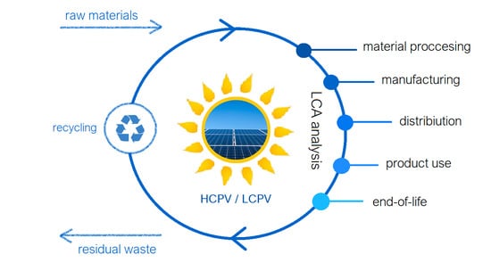
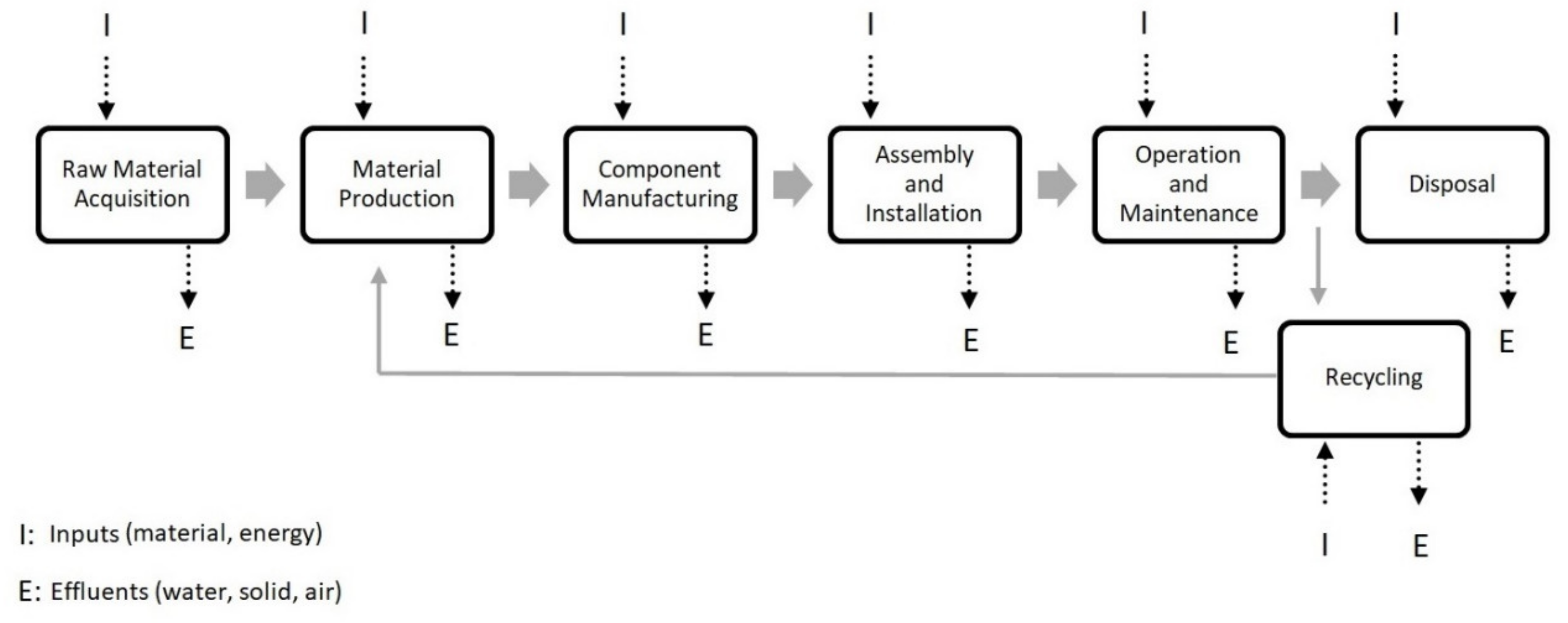
5. LCA of CPV Modules

The concentrated photovoltaic system offers many benefits compared to conventional photovoltaic technology, such as relatively high conversion efficiency, reduction of the costs by replacing expensive components, and elimination of toxic materials, especially involving the solar cell [54,55]. The rapid development of CPV technology brings benefits mainly by increasing the efficiency of systems, but it also requires environmental impact assessment. For this purpose, LCA has been successfully applied and CPV modules can be compared based on the LCA results. The standard stages of LCA for the photovoltaic technology are presented in Figure 1, according to Fthenakis [56]. The life cycle of photovoltaic panels consists of the following stages: production and acquiring the materials, as well as production, installation, operation, maintenance, and disposal/recycling of a particular module component. The collection of inventory data is one of the most time-consuming stages and largely affects the accuracy of LCA results. The inventory data can be collected from commercially available databases, e.g., Ecoinvent [57] or U.S. Life Cycle Inventory Database [58]. The results of LCA are useful for manufacturers and users to identify the competitiveness of CPV technologies available on the market. Basic parameters and LCA impact indicators for photovoltaics technology are summarized in Table 3.

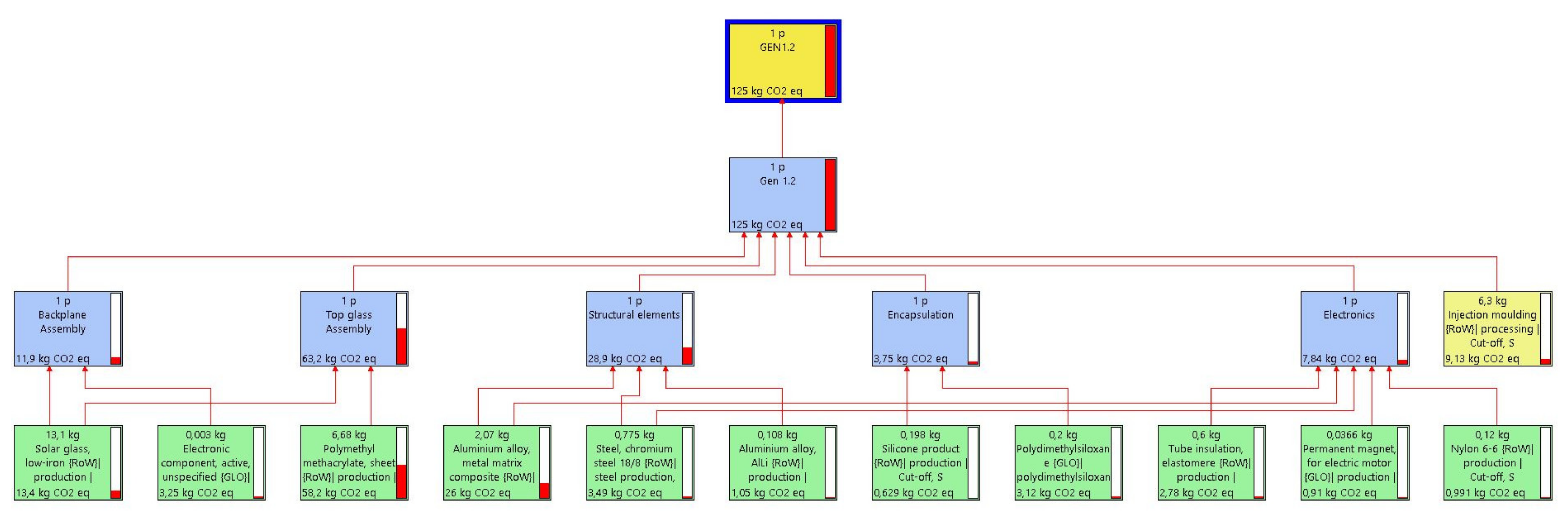
5.1. LCA of HCPV Modules

More than 90% of the CPV capacity that has been publicly documented to be installed through the end of 2016 is in the form of high-concentration PV with two-axis tracking [64]. One of the first HCPV modules developed in 2005 was FLATCON. The optics system based on Fresnel lenses and a multijunction solar cell (GaInP, GaInAs, and Ge) were used. The module operates for 500× concentrations, which allows achieving an efficiency near 26% with an optical aperture area of 25.6 m2. To evaluate the environmental impact, CED and EPBT were calculated for a FLATCON module installed in Spain. According to the results, the tracker production had the largest contribution to the CED and zinced steel, as their components had the most important energy factor of the system (embodied energy of about 29 MJ/kg). The EPBT was calculated in values between 8 to 10 months and was dominated by steel and glass elements of the module. Changing the FLATCON location would be unfavorable, and for installation in Germany, the EPBT increased to 12–16 months [60]. Minassians et al. [65] investigated the environmental impact of SolFocusGen1 HCPV systems installed in the United States. The optical design employed in the module consists of a concave primary mirror and a convex secondary mirror to concentrate sunlight onto the cell (500×) via a tertiary optical rod. The environmental impact of SolFocus technologies was produced mainly by steel elements in the tracking system. According to the LCA results, transportation of parts from New York to California accounted for a significant part of the total system environmental load; CED = 25%. The calculated EPBT was 1.3 and 1.5 years, for installation in Arizona and California, respectively, and could be lowered by a reduction in shipment distance [66,67,68,69]. Completed in 2013, the European project Apollon developed a new mirror-based HCPV module [70]. The supplier of the module was SoITec International. The optic elements were made from aluminum foil [68]. The optimization of the module was tested between 500 and 750× concentrations where the biggest challenge was the tracking system and materials used in the module. The first results of environmental impact analysis showed a carbon footprint between 18–45 g CO2.eq/kWh with 0.8–1.9 years EBPT [55]. At the final stage of the project, the EPBT was calculated for 1 year with 30% efficiency and a 30-year system lifetime with a power rating of 850 W/m2. The greatest environmental impact was found for aluminum, contributing 63% of the CED and 64% of the GHG emissions. This material also generated the biggest impact on the EPBT value. Finally, the carbon footprint was determined to be 20 g CO2.eq/kWh [70]. For several years, the leader in the HCPV industry in the USA and Europe was Amonix 7700 (now Arzon Solar) [56]. This system is based on seven concentrating units mounted on a two-axis tracker. Amonix 7700 had 7560 multijunction solar cells at a 500× concentration ratio. Solar cells were produced by Spectrolab using metal-organic vapor phase epitaxy (MOVPE) grown on a germanium substrate. Information about environmental impact based on the LCA methodology for Amonix 7700 was published by Fthenakis and co-workers [24,56,71]. As in the case of the FLATCON, it operates for 500× concentration, and its EPBT is close to 0.9 years. According to the LCA results, the solvents and MOVPE are materials responsible for great electricity consumption among all components of the solar cell. The highest GHG was calculated for tracker (28.4%), heat sink (28.2%), and frame (15.2%) [56]. Compared to the previously presented modules, Amonix 7700 generated the highest carbon footprint value, between 26–27 g CO2.eq/kWh, depending on the module location. Interestingly, Nishimura et al., based on LCA, determined the effect of HCPV location and PV type (HCPV versus flat-plate PV) on environmental load [72]. The results showed that EPBTs for HCPV with multijunction solar cells located in the Gobi Desert and Toyohashi (Japan) were 2 and 2.64 years, respectively. In the case of allocations of HCPV modules, manufacturing processes had the highest impact on the life cycle. Comparing HCPV flat-plate technologies with ms-Si PV (multi-crystalline silicon photovoltaic power generation system) in the Gobi Desert, surprisingly, the energy recovery characteristic of mc-Si PV is better (EPBT = 1.73 years). For the analyzed locations, the energy recovery characteristic of the mc-Si PV is better than that of HCPV, and these results are supported by the fact that mc-Si PV uses global solar radiation, whereas HCPV uses only direct solar radiation. The environmental impact of HCPV modules produced by Fullsun Photovoltaics Ltd. was determined by Sandwell et al. [68]. Compared to previous systems, the module construction is thinner and more lightweight, with dimensions close to conventional flat PV systems. The relatively low materials usage results in a low value of CED (4.3 MJ/Wp) in relation to the other technologies presented in Table 4. Moreover, the location of the modules has a major impact on economic aspects. The most favorable location was Calama ($0.037/kWh), where LCOE was significantly lower even compared to flat-plate PV modules. The LCA methodology was also used to determine the environmental impact of commercial 1.008 MWp HCPV plants in Morocco [73]. The conversion efficiency of the plant, which consists of 3600 modules, was close to 27.2%. The results showed emission of CO2 on the level of 53.3 kg CO2 eq/MWh, where raw material extraction and manufacturing are responsible for substantial emissions. Authors proved that by extending the lifetime of the HCPV plants from 20 to 30 years, the environmental impact of the system could be reduced by 23–31%. Based on LCA analysis, Payet and Greffe [74] compared three different prototypes of HCPV modules: mirror-based, Fresnel lens, and Achromalens. The climate change impact (expressed in g CO2-eq impact per process distribution) for the mirror-based optical design module was about 10% lower than the Achromalens modules. The main contribution to the environmental load was tracking and focusing optics equipment. The EPBT and CPBT for the prototypes range from 0.74–0.98 and 0.98–1.10 years, respectively. Recently, in the HIPERION project (hybrid photovoltaics for efficiency record using integrated optical technology) [75,76] novel, highly efficient solar modules (>30% STC—standard test conditions for solar module evaluation) based on planar optical micro-tracking that concentrates sunlight on multijunction solar cells mounted on top of a conventional silicon backplane have been developed. The panels work as silicon modules under diffuse sunlight, and provide an absolute record of energy generation per m2, with up to 50% gain in Central Europe and even 80% in Southern Europe. Figure 2 presents the results of LCA calculations regarding CO2 emissions and the contribution of the elements to the environmental load associated with the module production process. The figure illustrates a reduced process tree (only elements with a contribution higher than 0.5% are presented) showing the emission of CO2 eq. of individual materials used to manufacture the module.
The biggest load was generated by the production of PMMA (47%), the material of the panel, which concentrates solar light on solar cells, aluminum alloy (21%), and solar glass (11%). The total CO2 emission per HIPERION module was 125 kg eq, which results in low emission of CO2 g eq/kWh from 11 to 14.9 over the lifespan (25 years) (Table 4) [76].
With novel module architecture and manufacturing processes, HIPERION has the potential to reduce solar electricity costs by significantly boosting the efficiency and the energy yield per unit area well beyond the capabilities of crystalline silicon.
From the overview of available HCPV (Table 4), several conclusions can be drawn. The concentration ratio is around 500×, and most of the modules are based on a multijunction solar cell. The declared efficiency did not exceed 40% in any case. For the investigated HCPV modules, the EPBTs were around 1–2 years, and most of them had a CO2 footprint expressed as GHG less than 30 g CO2-eq./kWh. The tracking system had the biggest impact on the environmental life cycle among all HCPV components. Among the materials, aluminum, steel, and cement constitute the main source of GHG for Amonix 7700 [24] and HCPV by INER [77]; therefore, replacement with materials that have a lower carbon footprint could improve the environmental impact of HCPV modules.

5.2. LCA of LCPV Modules

Low-concentration photovoltaics (LCPV) compared to HCPV are a less common technology in the domain of CPV systems. However, LCPV has many underrated features. A significant advantage of using low-concentration photovoltaic systems rather than high-concentration is the higher angle of optical acceptance and the possibility of using cheaper trackers. LCPV modules also provide a wider range of materials that can be used for construction without any apprehension for solar degradation [80]. Importantly, compared to HCPV, LCPV systems can be deployed in more countries as they can work with lower direct normal irradiance (DNI). However, this feature can also be a drawback of LCPV systems, especially on a cloudy day where the trackers can easily become lost. As a consequence of low DNI values, trackers can be mistakenly focused on bright clouds rather than the sun rays. In comparison to the conventional PV modules, LCPV systems can achieve similar results on a yearly basis, which proves that they can be used interchangeably as building energy sources [55,81,82,83]. Moreover, a large number and variety of LCPV modules are technological solutions for building integrated concentrated photovoltaics (BICPV) [54]. In 2015, Lamnatou et al. [62] presented the studies of BICPV systems with a mono-crystalline solar cell. The environmental impact of the system was evaluated based on the carbon footprint (expressed as the GPBT) and the EPBT. The module was examined in five locations: Exeter, Barcelona, Madrid, Dublin, and Paris. For the GPBT, the highest values were obtained for modules working in Paris (27.2–33.1 years) that may be related to the low CO2 emission of France’s electricity mix and the lowest in Dublin (3.3–4 years). Taking into account the EPBT, the value obtained by Madrid and Barcelona is near 2.4 years, whereas by Paris, Exeter, and Dublin, the value was around 3.2–3.5 years. It was also found that the use of reflective film reduces the values by around 11–12% of the EPBT and GPBT [61]. Menoufi et al. [63] compared conventional BICPV to a novel low-concentration building added concentrating photovoltaic (BACPV). The modification of the previous system consisted of integrating reflectors to a building as a shading system with an inclination of 50° with respect to the horizontal plane, which reduced the EPBT to 1.0 years (2.2 years for BICPV). Energy ERF was also calculated for both technologies and was more than two times higher for BACPV.

6. End of Life and Recycling

Although photovoltaics is a source of renewable energy, the total environmental impact must be assessed throughout the entire life cycle of the system [84,85,86]. Photovoltaic modules at the end-of-life stage constitute an inevitable waste stream. The typical lifespan for PV modules is about 25–30 years.
This time can be shorter due to damage during the transportation and installation stages, initial failures after start-up operations, technical and physical failures during operation caused by severe environmental conditions, and unexpected external factors, e.g., natural disasters [87]. As the production of modules is sharply increasing, waste management is an important issue these days. Unfortunately, landfills are the main waste disposal methods for PV systems [86]. Several studies show the environmental consequences of improper management of PV waste, mainly due to the release of heavy metals [79,87,88,89,90]. Recycling of PV modules is an environmentally favorable method with numerous advantages compared to the landfill. It allows the controlled release of hazardous substances into the environment, saves precious and scarce metals (e.g., Ag, Ga, In), and alleviates lifecycle resource depletion [86]. Developing an appropriate recycling method of a particular component of PV modules is a key issue for the environment and can improve the sustainability of the photovoltaic industry. The majority of PV technologies on the market are crystalline Si-PV modules [89,90,91], and most recycling methods are dedicated to them.
A typical Si-PV panel consists of an aluminum (Al) alloy frame, tempered glass, a battery piece, EVA (ethylene/vinyl acetate copolymer), and a backboard (TPT, Topotecan Hydrochloride). Basic information about the materials obtained after disassembly and extraction of PV is presented in Table 5.
The weight of various resources from a typical solar panel is as follows: glass 54.7%, Al 12.7%, adhesive sealant 10%, silicon 3.1%, and other 19.5% [91,92]. The most suitable parts of the modules to recycle are steel and aluminum parts, which constitute above 80% of the whole composition of the module [42]. Other substances, such as concrete or acrylic, need additional preliminary processes, such as separating or sorting, before the start of the main recycling process. For typical PV modules, there are many recycling technologies studied around the world [92,93] that can also be slowly implemented into CPV systems. Among them, the most frequently used are shredding and methods using organic solvents, which allow for the recovery and reuse of many materials. The dismantling of CPV modules is easier because the constitutive elements are easily separable and are composed mostly of inorganic material that can be fully recycled. On the contrary, SI-PV cells and frames are completely bonded to complex, fluorinated plastics, which require advanced crushing and thermal treatment for partial recycling. The biggest challenge in the CPV modules is the recovery of gallium, germanium, and indium as they are hard-to-reach raw materials, despite the fact that they account for only about 1% of the total mass of the module. Fthenakis presented end-of-life processing for an Amonix 7700 module [56] based on the automobile recycling practices in which dismantling, shredding, and transportation were additionally considered in terms of economic aspects. Solar cells made of III-V semiconductors were disposed of as hazardous waste or recycled.
The LCA calculations for the HCPV HIPERION module show that waste management may increase the total carbon footprint of the module by about 5% [76].

7. Conclusions

Compared to conventional PV systems, the CPV is still an emerging technology; however, the results presented in the paper demonstrate the great potential of CPV systems to generate a huge amount of clean energy. Concentrated photovoltaics have an advantage over traditional Si-PVs, as they are nearly three times more efficient. The demonstrated CPV modules have the potential of reaching more than 30% module efficiency. HCPV and LCPV technologies differ according to the applied type of solar cells, optics, and concentration ratio. When comparing their effectiveness, care should be taken to distinguish whether they are related to cells, sub-modules, or systems. An important indicator of the environmental performance for PV is energy payback time calculated for particular systems. According to our survey, the conversion efficiency for HPCV is in the range of 0.22–2.6 years, whereas for LCPV, it ranges from 0.7–4.7 years with a very diverse distribution (Table 4).
The LCA method is becoming a more and more appreciated and useful tool, especially for assessing an environmental load of new technologies. Due to the vast diversity of CPV modules architecture, there is no clear answer to which elements of the module produce the biggest environmental load. For most of the constructions, the main contribution in the environmental burden is focusing optics (often more than 50% contribution in carbon footprint), tracking system, and the frame of the aluminum alloy or steel. Focusing optics have the most significant effect on the total carbon dioxide emissions, which makes the substantial reduction of the environmental impact of the CPV modules difficult, as this part of the panel cannot be replaced; however, due to the high efficiency of energy conversion of CPV panels, the carbon footprint produced by the module is in the range of 10–30 g CO2.eq/kWh, depending on the location.
The development of recycling and recovery methods for solar cells made of III-V semiconductors, currently disposed of as hazardous waste, or recycled, is an important issue for the environment and can improve the sustainability of the photovoltaic industry.
Comparative studies among CPV modules based on LCA results may support the choice of design alternatives already at the design stage.

Author Contributions

Conceptualization, A.Z.-S. and M.P.; methodology, A.Z.-S. software, A.Z.-S. and I.Z.; validation, A.Z.-S. and I.Z.; formal analysis, A.Z.-S. and I.Z.; investigation, A.Z.-S.; resources, M.P.; data curation, M.P.; writing—A.Z.-S. and M.P., writing—review and editing, A.Z.-S., M.P. and I.Z.; visualization, M.P.; supervision, I.Z.; project administration, I.Z.; funding acquisition, I.Z. All authors have read and agreed to the published version of the manuscript.

Funding

This project has received funding from the European Union’s Horizon 2020 research and innovation program under Grant Agreement No. 857775.

Conflicts of Interest

The authors declare no conflict of interest.

References

  1. Gielen, D.; Boshell, F.; Saygin, D.; Bazilian, M.D.; Wagner, N.; Gorini, R. The role of renewable energy in the global energy transformation. Energy Strateg. Rev. 2019, 24, 38–50. [Google Scholar] [CrossRef]
  2. Reyes-Belmonte, M.A. Quo Vadis Solar Energy Research? Appl. Sci. 2021, 11, 3015. [Google Scholar] [CrossRef]
  3. Pablo-Romero, M.D.P.; Román, R.; Sánchez-Braza, A.; Yñiguez, R. Renewable Energy, Emissions, and Health. In Renewable Energy—Utilisation and System Integration; Cao, W., Hu, Y., Eds.; IntechOpen: London, UK, 2016; pp. 173–198. [Google Scholar]
  4. Akella, A.K.; Saini, R.P.; Sharma, M.P. Social, economical and environmental impacts of renewable energy systems. Renew. Energy 2009, 34, 390–396. [Google Scholar] [CrossRef]
  5. Chukwuka, C.; Folly, K.A. Overview of Concentrated Photovoltaic (CPV) Cells. J. Power Energy Eng. 2014, 2, 1–8. [Google Scholar] [CrossRef] [Green Version]
  6. Boretti, A.; Castelletto, S.; Al-Zubaidy, S. Concentrating solar power tower technology: Present status and outlook. Nonlinear Eng. 2019, 8, 10–31. [Google Scholar] [CrossRef]
  7. Benhammane, M.; Notton, G.; Pichenot, G.; Voarino, P.; Ouvrard, D. Overview of electrical power models for concentrated photovoltaic systems and development of a new operational model with easily accessible inputs. Renew. Sustain. Energy Rev. 2021, 135, 110221. [Google Scholar] [CrossRef]
  8. Wiesenfarth, M.; Anton, I.; Bett, A.W. Challenges in the design of concentrator photovoltaic (CPV) modules to achieve highest efficiencies. Appl. Phys. Rev. 2018, 5, 041601. [Google Scholar] [CrossRef] [Green Version]
  9. Ju, X.; Xu, C.; Liao, Z.; Du, X.; Wei, G.; Wang, Z.; Yang, Y. A review of concentrated photovoltaic-thermal (CPVT) hybrid solar systems with waste heat recovery (WHR). Sci. Bull. 2017, 62, 1388–1426. [Google Scholar] [CrossRef] [Green Version]
  10. Piasecka, I.; Bałdowska-Witos, P.; Piotrowska, K.; Tomporowski, A. Eco-Energetical Life Cycle Assessment of Materials and Components of Photovoltaic Power Plant. Energies 2020, 13, 1385. [Google Scholar] [CrossRef] [Green Version]
  11. International Renewable Energy Agency—End-of-Life Management Solar Photovoltaic Panels, 2016. Available online: https://www.irena.org/publications/2016/Jun/End-of-life-management-Solar-Photovoltaic-Panels (accessed on 10 February 2021).
  12. Muteri, V.; Cellura, M.; Curto, D.; Franzitta, V.; Longo, S.; Mistretta, M.; Parisi, M.L. Review on life cycle assessment of solar photovoltaic panels. Energies 2020, 13, 252. [Google Scholar] [CrossRef] [Green Version]
  13. Beccali, M.; Cellura, M.; Finocchiaro, P.; Guarino, F.; Longo, S.; Nocke, B. Life Cycle Assessment performance comparison of small solar thermal cooling systems with conventional plants assisted with photovoltaics. Energy Procedia 2012, 30, 893–903. [Google Scholar] [CrossRef] [Green Version]
  14. ISO. ISO 14040. Environmental Management—Life Cycle Assessment —Principles and Framework; ISO: Geneva, Switzerland, 2006. [Google Scholar]
  15. ISO. ISO 14044. Environmental Management—Life Cycle Assessment —Requirements and Guidelines; ISO: Geneva, Switzerland, 2006. [Google Scholar]
  16. Brusseau, M.L. Sustainable Development and Other Solutions to Pollution and Global Change. Environ. Pollut. Sci. 2019, 585–603. [Google Scholar]
  17. Nieuwlaar, E. Life Cycle Assessment and Energy Systems. In Encyclopedia of Energy, 1st ed.; Cleveland, C.J., Ed.; Elsevier: Wisconsin, OH, USA, 2004; pp. 647–654. [Google Scholar]
  18. Gerbinet, S.; Belboom, S.; Léonard, A. Life Cycle Analysis (LCA) of photovoltaic panels: A review. Renew. Sustain. Energy Rev. 2014, 38, 747–753. [Google Scholar] [CrossRef]
  19. Fraunhofer ISE. Study: Levelized Cost of Electricity—Renewable Energy Technologies; Fraunhofer ISE: Freiburg, Germany, 2013. [Google Scholar]
  20. Khamooshi, M.; Salati, H.; Egelioglu, F.; Hooshyar Faghiri, A.; Tarabishi, J.; Babadi, S. A review of solar photovoltaic concentrators. Int. J. Photoenergy 2014, 958521. [Google Scholar] [CrossRef]
  21. Ralph, E.L. Use of concentrated sunlight with solar cells for terrestrial applications. Sol. Energy 1966, 10, 67–71. [Google Scholar] [CrossRef]
  22. Friedman, D.J. Concentrating and multijunction photovoltaics. In Fundamentals of Materials for Energy and Environmental Sustainability; Ginley, D.S., Kahen, D., Eds.; Cambridge University Press: New York, NY, USA, 2012; pp. 257–271. [Google Scholar]
  23. Salim, A.A.; Huraib, F.S.; Eugenio, F.S.; Lepley, T.C. Performance comparison of two similar concentrating PV systems operating in the US and Saudi Arabia. In Proceedings of the 19th IEEE Photovoltaic Specialists Conference, New Orleans, LA, USA, 4–8 May 1987; pp. 1351–1357. [Google Scholar]
  24. Fthenakis, V.M.; Kim, H.C. Life cycle assessment of high-concentration photovoltaic systems. Prog. Photovoltaics Res. Appl. 2013, 21, 379–388. [Google Scholar] [CrossRef]
  25. Wiesenfarth, M.; Steiner, M.; Dörsam, T.; Siefer, G.; Dimroth, F.; Nitz, P.; Bett, A.W. FLATCON® CPV module technology: A new design based on the evaluation of 10 years of outdoor measurement data. AIP Conf. Proc. 2019, 2149. [Google Scholar]
  26. Victoria-Pérez, M. New concepts and techniques for the development of high-efficiency concentrating photovoltaic modules. Ph.D. Thesis, Aarhus University, Aarhus, Denmark, 2014. [Google Scholar]
  27. Khatri, R.; Agarwal, S.; Saha, I.; Singh, S.K.; Kumar, B. Study on long term reliability of photo-voltaic modules and analysis of power degradation using accelerated aging tests and electroluminescence technique. Energy Procedia 2011, 8, 396–401. [Google Scholar] [CrossRef] [Green Version]
  28. Wohlgemuth, J.H.; Cunningham, D.W.; Monus, P.; Miller, J.; Nguyen, A. Long term reliability of photovoltaic modules. In Proceedings of the IEEE 4th World Conference on Photovoltaic Energy Conference, Waikoloa, HI, USA, 7–12 May 2006; pp. 2050–2053. [Google Scholar]
  29. Xiao, M.; Tang, L.; Zhang, X.; Lun, I.Y.F.; Yuan, Y. A Review on Recent Development of Cooling Technologies for Concentrated Photovoltaics (CPV) Systems. Energies 2018, 11, 3416. [Google Scholar] [CrossRef] [Green Version]
  30. Price, J.S.; Grede, A.J.; Wang, B.; Lipski, M.V.; Fisher, B.; Lee, K.-T.; He, J.; Brulo, G.S.; Ma, X.; Burroughs, S.; et al. High-concentration planar microtracking photovoltaic system exceeding 30% efficiency. Nat. Energy 2017, 2, 1–7. [Google Scholar] [CrossRef]
  31. Saito, K.; Abiko, Y.; Toya, K.; Mori, K.; Kogetsu, Y.; Iwasaki, T. Development of concentrator photovoltaic system. SEI Tech. Rev. 2013, 76, 23–26. [Google Scholar]
  32. King, R.R.; Law, D.C.; Edmondson, K.M.; Fetzer, C.M.; Kinsey, G.S.; Yoon, H.; Sherif, R.A.; Karam, N.H. 40% efficient metamorphic GaInPGaInAsGe multijunction solar cells. Appl. Phys. Lett. 2007, 90, 90–93. [Google Scholar] [CrossRef] [Green Version]
  33. Dimroth, F.; Grave, M.; Beutel, P.; Fiedeler, U.; Karcher, C.; Tibbits, T.N.D.; Oliva, E.; Siefer, G.; Schachtner, M.; Wekkeli, A.; et al. Wafer bonded four-junction GaInP/GaAs//GaInAsP/GaInAs concentrator solar cells with 44.7% efficiency. Prog. Photovoltaics Res. Appl. 2014, 22, 277–282. [Google Scholar] [CrossRef]
  34. Law, D.C.; King, R.R.; Yoon, H.; Archer, M.J.; Boca, A.; Fetzer, C.M.; Mesropian, S.; Isshiki, T.; Haddad, M.; Edmondson, K.M.; et al. Future technology pathways of terrestrial III-V multijunction solar cells for concentrator photovoltaic systems. Sol. Energy Mater. Sol. Cells 2010, 94, 1314–1318. [Google Scholar] [CrossRef]
  35. Domínguez, C.; Jost, N.; Askins, S.; Victoria, M.; Antón, I. A review of the promises and challenges of micro-concentrator photovoltaics. AIP Conf. Proc. 2017, 1881, 080003. [Google Scholar]
  36. Steiner, M.; Bösch, A.; Dilger, A.; Dimroth, F.; Dörsam, T.; Muller, M.; Hornung, T.; Siefer, G.; Wiesenfarth, M.; Bett, A.W. FLATCON® CPV module with 36.7% efficiency equipped with four-junction solar cells. Prog. Photovoltaics Res. Appl. 2015, 23, 1323–1329. [Google Scholar]
  37. Philipps, S.P.; Bett, A.W.; Horowitz, K.; Kurtz, S. Current Status of Concentrator Photovoltaic (CPV) Technology ; Technical Report of National Renewable Energy Lab; National Renewable Energy Lab (NREL): Golden, CO, USA, 2015. [CrossRef]
  38. Fernández, E.F.; Almonacid, F.; Rodrigo, P.M.; Pérez-Higueras, P.J. CPV systems. In McEvoy’s Handbook of Photovoltaics, 3rd ed.; Kalogirou, S., Ed.; Academic Press: London, UK, 2018; pp. 931–985. [Google Scholar]
  39. Lee, C.Y.; Chou, P.C.; Chiang, C.M.; Lin, C.F. Sun tracking systems: A review. Sensors 2009, 9, 3875–3890. [Google Scholar] [CrossRef] [PubMed]
  40. AL-Rousan, N.; Isa, N.A.M.; Desa, M.K.M. Advances in solar photovoltaic tracking systems: A review. Renew. Sustain. Energy Rev. 2018, 82, 2548–2569. [Google Scholar] [CrossRef]
  41. Ferdaus, R.A.; Mohammed, M.A.; Rahman, S.; Salehin, S.; Mannan, M.A. Energy Efficient Hybrid Dual Axis Solar Tracking System. J. Renew. Energy 2014, 2014, 629717. [Google Scholar] [CrossRef]
  42. Ignacio Luque-Heredia, I.; Magalhães, P.; Muller, M. CPV Tracking and Trackers. In Handbook of Concentrator Photovoltaic Technology, 1st ed.; Algora, C., Rey-Stolle, I., Eds.; John Wiley&Sons Inc.: Chichester, UK, 2016; pp. 293–338. [Google Scholar]
  43. Damiano, A.; Marongiu, I.; Musio, C.; Musio, M. Concentrator photovoltaic standards: Experimental analyses of technical requirements. In Proceedings of the IECON 2013 - 39th Annual Conference of the IEEE Industrial Electronics Society, Vienna, Austria, 10–14 November 2013; pp. 8074–8079. [Google Scholar]
  44. Lin, G.J.; Bi, J.; Song, M.; Liu, J.; Xiong, W.; Huang, M. III-V Multi-Junction Solar Cells. In Optoelectronics—Advanced Materials and Devices; Pyshkin, S.L., Ballato, J.M., Eds.; IntechOpen: London, UK, 2013; pp. 445–471. [Google Scholar]
  45. Miller, D.C.; Gedvilas, L.M.; To, B.; Kennedy, C.E.; Kurtz, S.R. Durability of poly(methyl methacrylate) lenses used in concentrating photovoltaic modules. Reliab. Photovolt. Cells, Modul. Components Syst. III 2010, 7773, 777303. [Google Scholar]
  46. Hayashi, N.; Terauchi, M.; Aya, Y.; Kanayama, S.; Nishitani, H.; Nakagawa, T.; Takase, M. Thin concentrator photovoltaic module with micro-solar cells which are mounted by self-align method using surface tension of melted solder. AIP Conf. Proc. 2017, 1881, 080005. [Google Scholar]
  47. Hayashi, N.; Matsushita, A.; Inoue, D.; Matsumoto, M.; Nagata, T.; Higuchi, H.; Aya, Y.; Nakagawa, T. Nonuniformity sunlight-irradiation effect on photovoltaic performance of concentrating photovoltaic using microsolar cells without secondary optics. IEEE J. Photovoltaics 2016, 6, 350–357. [Google Scholar] [CrossRef]
  48. Ghosal, K.; Lilly, D.; Gabriel, J.; Whitehead, M.; Seel, S.; Fisher, B.; Wilson, J.; Burroughs, S. Semprius field results and progress in system development. IEEE J. Photovoltaics 2014, 4, 703–708. [Google Scholar] [CrossRef]
  49. Abad, D.; San Miguel, G.; Domínguez, C.; Jost, N.; Guti, F. Environmental and Economic LCI of a micro-CPV module. In Proceedings of the 16th International Conference on Environmental Science and Technology, Rhodes, Greece, 4–7 September 2019; pp. 3–4. [Google Scholar]
  50. Krarti, M. Integrated Design of Communities. In Optimal Design and Retrofit of Energy Efficient Buildings, Communities, and Urban Centers; Krarti, M. Butterworth-Heinemann: Oxford, UK, 2018; pp. 385–470. [Google Scholar]
  51. Yoon, J.; Lee, S.M.; Kang, D.; Meitl, M.A.; Bower, C.A.; Rogers, J.A. Heterogeneously Integrated Optoelectronic Devices Enabled by Micro-Transfer Printing. Adv. Opt. Mater. 2015, 3, 1313–1335. [Google Scholar] [CrossRef]
  52. Tien, N.X.; Shin, S. A novel concentrator photovoltaic (CPV) system with the improvement of irradiance uniformity and the capturing of diffuse solar radiation. Appl. Sci. 2016, 6, 251. [Google Scholar] [CrossRef] [Green Version]
  53. Yamada, N.; Hirai, D. Maximization of conversion efficiency based on global normal irradiance using hybrid concentrator photovoltaic architecture. Prog. Photovoltaics Res. Appl. 2016, 24, 846–854. [Google Scholar] [CrossRef]
  54. Chemisana, D. Building integrated concentrating photovoltaics: A review. Renew. Sustain. Energy Rev. 2011, 15, 603–611. [Google Scholar] [CrossRef]
  55. Lamnatou, C.; Chemisana, D. Concentrating solar systems: Life Cycle Assessment (LCA) and environmental issues. Renew. Sustain. Energy Rev. 2017, 78, 916–932. [Google Scholar] [CrossRef] [Green Version]
  56. Fthenakis, V. Life Cycle Analysis of CPV Systems. In Handbook of Concentrator Photovoltaic Technology, 1st ed.; Algora, C., Rey-Stolle, I., Eds.; John Wiley&Sons Inc: Chichester, UK, 2016; pp. 685–704. [Google Scholar]
  57. Wernet, G.; Bauer, C.; Steubing, B.; Reinhard, J.; Moreno-Ruiz, E.; Weidema, B. The ecoinvent database version 3 (part I): Overview and methodology. Int. J. Life Cycle Assess. 2016, 21, 1218–1230. [Google Scholar] [CrossRef]
  58. U.S. Life Cycle Inventory Database. National Renewable Energy Laboratory. 2012. Available online: https://www.lcacommons.gov/nrel/search (accessed on 11 February 2021).
  59. Palanov, N. Life-Cycle Assessment of Photovaltaic Systems. Master’s Thesis, Lund University (LTH), Lund, Sweden, 2014. [Google Scholar]
  60. Peharz, G.; Dimroth, F. Energy payback time of the high-concentration PV system FLATCON®. Prog. Photovoltaics Res. Appl. 2005, 13, 627–634. [Google Scholar] [CrossRef]
  61. Frischknecht, R.; Heath, G.; Raugei, M.; Sinha, P.; de Wild-Scholten, M.; Fthenakis, V.; Kim, H.C. Methodology Guidelines on Life Cycle Assessment of Photovoltaic Electricity, 3rd ed.; International Energy Agency (IEA): France, Paris, 2016. [Google Scholar]
  62. Lamnatou, C.; Baig, H.; Chemisana, D.; Mallick, T.K. Life cycle energy analysis and embodied carbon of a linear dielectric-based concentrating photovoltaic appropriate for building-integrated applications. Energy Build. 2015, 107, 366–375. [Google Scholar] [CrossRef]
  63. Menoufi, K.; Chemisana, D.; Rosell, J.I. Life cycle assessment of a building added concentrating photovoltaic system (BACPV). Energy Procedia 2017, 128, 194–201. [Google Scholar] [CrossRef]
  64. Wiesenfarth, W.; Philipps, S.P.; Bett, A.W. Current Status of Concentrator Photovoltaic (CPV) Technology Version 1.3; Fraunhofer Institute for Solar Energy Systems ISE: Freiburg, Germany, 2017. [Google Scholar]
  65. Minassians, A.D.; Farshchi, R.; Nelson, J.; Weiser, C.R.; Zhang, T. Energy Payback Time of a SolFocus Gen1 Concentrator PV System; Final Project Report (MSE-ER C226—Photovoltaic Materials); University of California: Berkeley, CA, USA, 2006. [Google Scholar]
  66. Halasah, S.A.; Pearlmutter, D.; Feuermann, D. Field installation versus local integration of photovoltaic systems and their effect on energy evaluation metrics. Energy Policy 2013, 52, 462–471. [Google Scholar] [CrossRef]
  67. Peng, J.; Lu, L.; Yang, H. Review on life cycle assessment of energy payback and greenhouse gas emission of solar photovoltaic systems. Renew. Sustain. Energy Rev. 2013, 19, 255–274. [Google Scholar] [CrossRef]
  68. Sandwell, P.; Duggan, G.; Nelson, J.; Ekins-Daukes, N. The environmental impact of lightweight HCPV modules: Efficient design and effective deployment. Prog. Photovoltaics Res. Appl. 2016, 24, 1458–1472. [Google Scholar] [CrossRef]
  69. Sandwell, P.R.; Nelson, J.; Ekins-daukes, N. Assessing the potential for photovoltaic technology to mitigate greenhouse gas emissions. Ph.D. Thesis, Department of Physics Imperial College, London, UK, 2017. [Google Scholar]
  70. European Commission. Multi-APprOach for High Efficiency Integrated and InteLLigent cONcentrating PV Modules (Systems) Final Report Summary—APOLLON; European Commission: Brussels, Belgium, 2013. [Google Scholar]
  71. Fthenakis, V.M.; Kim, H.C. Photovoltaics: Life-cycle analyses. Sol. Energy 2011, 85, 1609–1628. [Google Scholar] [CrossRef]
  72. Nishimura, A.; Hayashi, Y.; Tanaka, K.; Hirota, M.; Kato, S.; Ito, M.; Araki, K.; Hu, E.J. Life cycle assessment and evaluation of energy payback time on high-concentration photovoltaic power generation system. Appl. Energy 2010, 87, 2797–2807. [Google Scholar] [CrossRef]
  73. Corona, B.; Escudero, L.; Quéméré, G.; Luque-Heredia, I.; San Miguel, G. Energy and environmental life cycle assessment of a high concentration photovoltaic power plant in Morocco. Int. J. Life Cycle Assess. 2017, 22, 364–373. [Google Scholar] [CrossRef]
  74. Payet, J.; Greffe, T. Life Cycle Assessment of New High Concentration Photovoltaic (HCPV) Modules and Multi-Junction Cells. Energies 2019, 12, 2916. [Google Scholar] [CrossRef] [Green Version]
  75. HIPERION Project Website. Available online: https://hiperion-project.eu (accessed on 8 March 2021).
  76. Zieminska-Stolarska, A.; Zbicinski, I. Report 2, Life cycle and energy payback time analysis, 2020, HIPERION Project Grant No. 857775—confidential.
  77. Cellura, M.; Grippaldi, V.; Lobrano, V.; Longo, S.; Mistretta, M.; Cellura, M.; Grippaldi, V.; Brano, V.; Longo, S.; Mistretta, M. Life cycle assessment of a solar PV/T concentrator system. In Proceedings of the Life Cycle Management Conference LCM, Berlin, Germany, 28–31 August 2011. [Google Scholar]
  78. De Feo, G.; Forni, M.; Petito, F.; Renno, C. Life cycle assessment and economic analysis of a low concentrating photovoltaic system. Environ. Technol. 2016, 37, 2473–2482. [Google Scholar] [CrossRef]
  79. Li, G.; Xuan, Q.; Pei, G.; Su, Y.; Lu, Y.; Ji, J. Life-cycle assessment of a low-concentration PV module for building south wall integration in China. Appl. Energy 2018, 215, 174–185. [Google Scholar] [CrossRef]
  80. Hu, A.H.; Huang, L.H.; Lou, S.; Kuo, C.H.; Huang, C.Y.; Chian, K.J.; Chien, H.T.; Hong, H.F. Assessment of the carbon footprint, social benefit of carbon reduction, and energy payback time of a high-concentration photovoltaic system. Sustainability 2017, 9, 27. [Google Scholar] [CrossRef] [Green Version]
  81. Schuetz, M.A.; Shell, K.A.; Brown, S.A.; Reinbolt, G.S.; French, R.H.; Davis, R.J. Design and construction of a ∼7× low-concentration photovoltaic system based on compound parabolic concentrators. IEEE J. Photovoltaics 2012, 2, 382–386. [Google Scholar] [CrossRef]
  82. Famoso, F.; Lanzafame, R.; Maenza, S.; Scandura, P.F. Performance comparison between low concentration photovoltaic and fixed angle PV systems. Energy Procedia 2015, 81, 516–525. [Google Scholar] [CrossRef] [Green Version]
  83. Aldegheri, F.; Baricordi, S.; Bernardoni, P.; Brocato, M.; Calabrese, G.; Guidi, V.; Mondardini, L.; Pozzetti, L.; Tonezzer, M.; Vincenzi, D. Building integrated low concentration solar system for a self-sustainable Mediterranean villa: The Astonyshine house. Energy Build. 2014, 77, 355–363. [Google Scholar] [CrossRef]
  84. Deng, R.; Chang, N.L.; Ouyang, Z.; Chong, C.M. A techno-economic review of silicon photovoltaic module recycling. Renew. Sustain. Energy Rev. 2019, 109, 532–550. [Google Scholar] [CrossRef]
  85. Komoto, K.; Lee, J.S. End-of-Life Management of Photovoltaic Panels: Trends in PV Module Recycling Technologies; Technical reports; IEA: Paris, France, 2018. [Google Scholar] [CrossRef]
  86. Nain, P.; Kumar, A. Metal dissolution from end-of-life solar photovoltaics in real landfill leachate versus synthetic solutions: One-year study. Waste Manag. 2020, 114, 351–361. [Google Scholar] [CrossRef] [PubMed]
  87. Fthenakis, V.M. End-of-life management and recycling of PV modules. Energy Policy 2000, 28, 1051–1058. [Google Scholar] [CrossRef] [Green Version]
  88. Kang, S.; Yoo, S.; Lee, J.; Boo, B.; Ryu, H. Experimental investigations for recycling of silicon and glass from waste photovoltaic modules. Renew. Energy 2012, 47, 152–159. [Google Scholar] [CrossRef]
  89. D’Adamo, I.; Miliacca, M.; Rosa, P. Economic Feasibility for Recycling of Waste Crystalline Silicon Photovoltaic Modules. Int. J. Photoenergy 2017, 2017, 4184676. [Google Scholar] [CrossRef]
  90. Latunussa, C.; Mancini, L.; Blengini, G.; Ardente, F.; Pennington, D. Analysis of Material Recovery from Silicon Photovoltaic Panels; EU-European Commission: Brussels, Belgium, 2016. [Google Scholar] [CrossRef]
  91. Xu, Y.; Li, J.; Tan, Q.; Peters, A.L.; Yang, C. Global status of recycling waste solar panels: A review. Waste Manag. 2018, 75, 450–458. [Google Scholar] [CrossRef] [PubMed]
  92. Strachala, D.; Hylský, J.; Vanĕk, J.; Fafilek, G.; Jandová, K. Methods for recycling photovoltaic modules and their impact on environment and raw material extraction. Acta Montan. Slovaca 2017, 22, 257–269. [Google Scholar]
  93. Lunardi, M.M.; Alvarez-Gaitan, J.P.; Bilbao, J.I.; Corkish, R. A Review of Recycling Processes for Photovoltaic Modules. In Solar Panels and Photovoltaic Materials; Zaidi, B., Ed.; IntechOpen: London, UK, 2018; pp. 9–27. [Google Scholar]
Figure 1. Stage of LCA analysis for photovoltaic modules [55].
Energies 14 03143 g001
Figure 2. Reduced process tree showing emission of CO2 eq of individual materials used to manufacture the module for HIPERION.
Energies 14 03143 g002
Table 1. Types and characterization of sun trackers for CPV according to Fernández et al. [38].
Single-Axis TrackersTwo-Axis Trackers
CharacterizationTracking the sun by rotation in one axis
Advantage: simple construction and lower costs
Disadvantage: impossible to set collector’s aperture perpendicularly to the sunlight all the time—collection of solar energy is insufficient to maintain the maximum
Tracking with two rotational axes, which angles CPV modules perpendicularly to the sun rays
Advantage: flexibility, higher energy output
Disadvantage: mechanical complexity
OptionsHorizontal axis—parallel to the ground; oriented along East–West or North–South directionTwo-axis tracker for point-focus CPV dish (a)
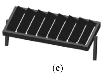
Vertical axis—collinear with the ZenithTwo-axis tracker for point-focus CPV module:
—Pedestal-mounted tracker (b)
—Carousel (rotate-and-roll) tracker (c)
—Tilt-and-roll tracker (d)
Inclined axis—inclined to the ground; oriented along North–South direction
Energies 14 03143 i001 Energies 14 03143 i002 Energies 14 03143 i003 Energies 14 03143 i004
Table 2. Life expectancies of HCPV system components [12].
ComponentLife Cycle Span (Years)
Two-axis tracker30
HCPV module30
Cables30
Manufacturing plant30
Inverter15
Transformer10
Table 3. Selected coefficient of the environmental impact assessment method.
ParameterDefinitionReference
FUFunctional Unit—A quantified measure of the system performance; generally, 1 kilowatt-hour (kWh) of produced electricity from converted solar irradiation (defined in stage 1 of LCA)[59]
EPBTEnergy Payback Time—A period required for a renewable energy system to generate the same amount of energy that was used to produce the system itself[60]
GHGGreen House Gas emission during the life cycle stages of a PV system is estimated as an equivalent of CO2 using an integrated 100-year time horizon using the most recent global warming potential factors published by the IPCC[61]
GPBTGreenhouse Payback Time—A measure of the years needed, e.g., for a PV system to balance the emissions of greenhouse gases[62]
CEDCumulative Energy Demand describes the consumption of fossil, nuclear and renewable energy sources along the life cycle of a product or a service[60,61]
PRPerformance Ratio percentage of real converted solar energy from theoretically possible under standard testing conditions[59]
EROIEnergy Return on the Investment—Calculated as system lifetime to EPBT ratio; it shows how easy (in energy terms) it is to exploit the available primary energy sources by investing a given amount of energy which one already has at own disposal[62]
ERFEnergy Return Factor—Calculated as a sum of total primary energy output produced during the entire lifetime of the system to the CED ratio[63]
Table 4. Review of life cycle assessment of HCPV and LCPV modules.
TechnologyLocationSolar CellCRDimension/
Aperture Area
Module Efficiency [%]CO2 Footprint GHG Emissions [g CO2-eq./kWh]EPBTOther InformationYearSource
HCPV
FLATCONSpainIII-V MJSC>500×25.6 (28.8) m226.018.08–16 months-CED 5.8 MJ/Wp
-DNI 2093 kWh/m2
2005[60,68]
SolFocusGen1Berkeley (B), California
Phoenix (P), Arizona
III-V MJSC500×na25.0na1.5 years (C)
1.3 years (A)
-CED 12.9 MJ/Wp
-Energy return factor (ERF) 33.2
2006[65,66,67,68,69]
ApollonItalyIII-V MJSC500–750×na34.020.012 months-CED 8.3 MJ/Wp
-DNI 1794 2093 kWh/m2
2008[68,70]
AmonixLas Vegas (LV)
Phoenix (P)
Glendale (G)
III-V MJSC500×267 m237.026.0 (LV)
27.0 (P,G)
0.9 years
(~11 months)
-DNI 2600 kWh/m2 (LV) 2480 kWh/m2 (P), 2570 kWh/m2 (G)
-system life time—30 years
-CED 11.8 MJ/Wp
2009[24,56,71]
SharpGobi Desert (G)
Toyohashi (T)
III-V MJSC90.7%10.9 m218.8 (G)
18.0 (T)
na2 years (G)
2.64 years (T)
-comparison of HCPV technology with ms-Si PV based on LCA results2010[72]
7.5 kW CPV by INERTaoyuan, JapanIII-V MJSC476×34.56 m230.0107.692.61 years-grid transmission loss 3.74%
-system lifetime—30 years
-DNI 909 kWh/m2
2016[77]
Fullsun HCPV modulePhoenix (P), USA
Seville(S), Spain
Tabuk (T), Saudi Arabia
Haixi (H), China
Alice Springs (AS), Australia
Calama (C), Chile
III-V MJSC625×450 × 600 × 48 mm/0.27 m234.09.0 (P)
9.4 (S)
8.3 (T)
9.8 (H)
8.8 (AS)
6.5 (C)
0.30 year (P)
0.32 year (S)
0.28 year (T)
0.33 year (H)
0.29 year (AS)
0.22 year (C)
-system lifetime—30 years
-CED 4.3 MJ/Wp-
DNI 2482 (P), 2278 (S), 2668 (T), 2409 (H), 2668 (AS), 3322 (C) kWh/m2/yr
-CPBT 0.48 (P), 0.88 (S), 0.30 (T), 0.35 (H), 0.29 (AS), 0.40 (C)
-LCOE—the lowest $0.037/kWh (C), the highest $0.055/kWh (S)
2016[68]
1.008 MWp HCPV plantCasablanca, MaroccoIII-V MJSC820×3600 m228.253.71.457 year-system lifetime—20 years
-human toxicity 44.1 kg 1.4-DB eq/MWh
-marine ecotoxicity 1.20 g 1.4-DB eq/kWh
-overall CED 18.83 × 10⁶ MJ
-DNI 1834 kWh/Wp
2016[73]
CPVMatchCatania, ItalyIII-V FJSC>800× (M)
>320× (F,A)
0.986 m2 (M)
0.320 m2 (F,A)
36.7% (M)
41.4% (A)
16.4 (M) 18.4 (A)0.74–0.98 year-comparison of different concentrating technology of HCPV: mirror (M), Fresnel lens (F) and Achromalens (A)2019[74]
HiperionMadrid, LyonIII-V MJSCnana29.011–15naDNI 2207 kWh/m22020[75,76]
LCPV
Building Integrated BIPVExeter (E)
Barcelona (B)
Madrid (M)
Dublin (D)
Paris (P)
Mono-crystalline Si solar cell2.8×1160 × 740 × 185 mm/0.036 m211.893–101 (MB)2–4 years (B,M)-GPBT 27.2–33.1 years (P) 3.3–5.7 years (E,D,B,M)
-comparison of two configurations: with reflective film and without
2015[62]
Building added BACPVSpainSingle crystalline Si10×48 × 36 mm—CPV cell (52 cells in module)nana1 year-comparison of two conventional BIPV
-ERF 32
2017[63]
Low Concentrating Photovoltaic-Thermal (CPVT)Palermo, ItalyCrystalline Si-10 m2nana0.7 year-LCPV installed on the roof
-solar thermal collectors
2011[77]
LCPV 2×ItalyPoly-crystalline Si0.156 × 0.156 m2 PV area (60 cells in module)na54.0na-comparison with traditional PV
-economic analysis
-ReCiPe
2016[78]
aCPC-PVChina 1.74×100 × 100 mm2nana2.82–4.74 years-environmental indicators are calculated for five cities in China: Beijing, Hefei, Lhasa, Lanzhou, Harbin
-CED 12.2 MJ/Wp
-GWP 1.09 kg CO2-ef./Wp
-possible application in BICPV
2018[79]
na—No available data.
Table 5. Composition of typical crystalline silicon solar panels and recovery methods of raw materials [91].
ComponentMaterialApproximate ContentRecovery
Framealuminum18%aluminum scrap suitable for producing secondary aluminum
Cablestinned wire2%copper recovery from cable scrap (~97%)
polymer (e.g., PVC) recovery of energy from incineration of polymer (~2.86 MJ/kg)
Top surfaceglass70%glass cullet for glass production (consumption 25% less energy compared to normal glass manufacture)
Encapsulation layerEVA, adhesive layer5%Energy recovery from incineration process (~3.5 MJ/kg of electricity)
Back-sheet layerPolyvinyl fluoride1.5%Energy recovery from incineration process
Solar cellSilicon 4%recovery rate of silicon ~95% and may substitute silicon metal
Metallization of modulessilver0.05%recovered through electrolysis or precipitation in leaching solution
Publisher’s Note: MDPI stays neutral with regard to jurisdictional claims in published maps and institutional affiliations.

