Article

Design of a Medium Voltage Generator with DC-Cascade for High Power Wind Energy Conversion Systems †

1
Department Converters and Drive Technology, Fraunhofer Institute for Energy Economics and Energy System Technology, 34119 Kassel, Germany
2
Institute of Technology, Resource and Energy-Efficient Engineering, Bonn-Rhein-Sieg University of Applied Sciences, 53757 Sankt Augustin, Germany
3
Institute for Drive Systems and Power Electronics, Leibniz University Hannover, 30167 Hannover, Germany
4
Corporate Technology, Siemens AG, 91058 Erlangen, Germany
5
Flender GmbH, Vogelweiherstr. 1-15, 90441 Nürnberg, Germany
*
Authors to whom correspondence should be addressed.
This paper is an extended version of our paper “Design of a Medium Voltage Generator and Power Converter for High Power Wind Energy Conversion Systems” published in Verifying the targets 2020 55th International Universities Power Engineering Conference (UPEC) Torino, Italy, 1–4 September 2020.
These authors contributed equally to this work.
Energies 2021, 14(11), 3106; https://doi.org/10.3390/en14113106
Submission received: 19 March 2021 / Revised: 6 May 2021 / Accepted: 20 May 2021 / Published: 26 May 2021

Abstract

:
This paper shows a new concept to generate medium voltage (MV) in wind power application to avoid an additional transformer. Therefore, the generator must be redesigned with additional constraints and a new topology for the power rectifier system by using multiple low voltage (LV) power rectifiers connected in series and parallel to increase the DC output voltage. The combination of parallel and series connection of rectifiers is further introduced as DC-cascade. With the resulting DC-cascade, medium output voltage is achieved with low voltage rectifiers and without a bulky transformer. This approach to form a DC-cascade reduces the effort required to achieve medium DC voltage with a simple rectifier system. In this context, a suitable DC-cascade control was presented and verified with a laboratory test setup. A gearless synchronous generator, which is highly segmented so that each segment can be connected to its own power rectifier, is investigated. Due to the mixed AC and DC voltage given by the DC-cascade structure, it becomes more demanding to the design of the generator insulation, which influences the copper fill factor and the design of the cooling system. A design strategy for the overall generator design is carried out considering the new boundary conditions.

1. Introduction

This paper is an extended version of [1]. The trend for wind power applications, especially for offshore wind energy conversion systems (WECS), is moving towards a rated output power of 10 to 15 MW for individual turbines [2,3,4]. As explained in [2], turbines with doubly fed induction generators and partial rectifiers have the highest market share today, while turbines with synchro or induction generators and a full-size rectifier will dominate the market in the future. In this paper a variable speed WECS with full-size power rectifier are investigated while the focus is on the generator and the power rectifier system. The converter and the generator of the WECS are in most cases designed in low voltage and only in rare cases directly as a medium voltage machine with medium voltage converter [2,3]. The state-of-the-art power rectifier topology for offshore wind power applications are parallel back-to-back two-level voltage source rectifiers. A round 10 back-to-back stacks, each with typically 0.75–1.5 MW rated power, are connected in parallel to reach the total rated power of 10 MW [2,4,5,6,7,8,9]. Typically, the connection to the medium voltage grid is realized via a transformer.
Based on the trend towards higher power [10,11] introducing a segmented permanent magnet synchronous generator (PMSG) with a rated power of P N = 10   MW for direct driven wind turbines. From the DTU 10 MW reference turbine [12], the essential boundary conditions are derived. The designed generator has a total number of p = 144 pole pairs to handle the direct driven rated rotor speed of n N = 10   min 1 with n S e g = 48 individual three-phase segments with three pole pairs. An electrical frequency of f S e g = 24   Hz results for the strongly segmented PMSG. In the presented approach every segment of the WECS is connected to a singly power rectifier. The active power of each segment is calculated by
P S e g = P N n S e g 208   kW .
Taking into account a power factor c o s φ > 0.8 the rated power of the individual rectifiers are results to
S Seg = P Seg cos ( φ ) 260   kVA
if each segment is coupled with its own power rectifier. As machine side rectifier, a simple three-phase two-level IGBT power converter is used.
By equipping each segment with a separate rectifier, it is possible to optimize reliability and efficiency or to damp mechanical vibrations of the generator as shown in [13,14]. A proof of concept of the segmented PMSG design was done with a scaled-down demonstrator. Figure 1 depicts the 200 kVA PMSG demonstrator with 12 segments. However, this paper focuses on increasing the DC voltage to medium voltage of the rectifier system and the corresponding design of the generator. The special design of the presented highly segmented PMSG with machine rectifiers for each segment results in a degree of freedom. The freedom in the connection of the rectifiers is used to form a DC-cascade with in series connected machine side rectifiers. With the resulting DC-cascade, the medium output voltage is achieved with low-voltage rectifiers only and the otherwise required transformer is avoided.
In wind power application, the market share of MV generators and converters is low, due to the limited availability of generators and less knowledge of the operation [2]. Nevertheless, in the few wind power applications the generator has a medium voltage winding that is directly connected to a medium voltage rectifier system [2,3]. In an industrial drive application, the use of medium voltage generators is more common. The AC voltage is generated in a typical range from U A C = 1   kV to 14   kV [15,16,17,18]. The study [17] shows two design approaches with different winding options. The discussed winding design is also found in LV machines. A key difference between LV and MV machines is the insulation, which must withstand higher voltage in MV applications. The design strategy for a conventional medium voltage insulation has been well evaluated in other applications such as a transformer [19,20,21]. Publications about a medium voltage insulation and permanent magnet synchronous generator are rare and usually focus on single issues [22,23,24]. Therefore, a design strategy for medium voltages generators considering mixed AC- and DC-voltage is given and compared with the low voltage design based on designs presented in [10,11,25].
For the medium voltage rectifier system different topologies are common. A simple solution for MV rectifier are a two-level converter with series connected switching devices, but the simultaneous switching leads to difficulties in operation [18,26,27]. Neutral point clamped (NPC) and active neutral point clamped (ANPC) are widely used in MV drive and wind power application [18,26,28,29,30]. NPC and ANPC topologies are built up in several levels, whereby seven to nine levels are not uncommon. The higher the number of levels, the higher the usable voltage, but the regulation and control also becomes correspondingly more complex. The previously mentioned converters usually used in the drive industry all have in common that the generator itself is designed as a medium voltage machine, i.e., the output voltage of the generator is already at medium voltage level. The concept of cascaded H bridges (CHB) presented in [26,31,32,33,34,35,36] is used to increase the low voltage of the machine to a medium grid voltage level by connecting H bridges in series at the grid output. Thus, the CHB is quite similar to the DC-cascade approach, with the difference that in the DC-Cascade the DC outputs are connected in series. Cascaded H bridges are H bridges connected in series at the AC output. By connecting the H bridges in series, an output voltage corresponding to the number of stages can be provided. The higher the number of stages, the higher the output voltage.
With the presented DC-cascade approach, it is possible to reach the medium voltage level while keeping the generator output voltage at low voltage level. The concept of forming a DC-cascade reduces the effort required to achieve a medium DC voltage with a simple rectifier system.

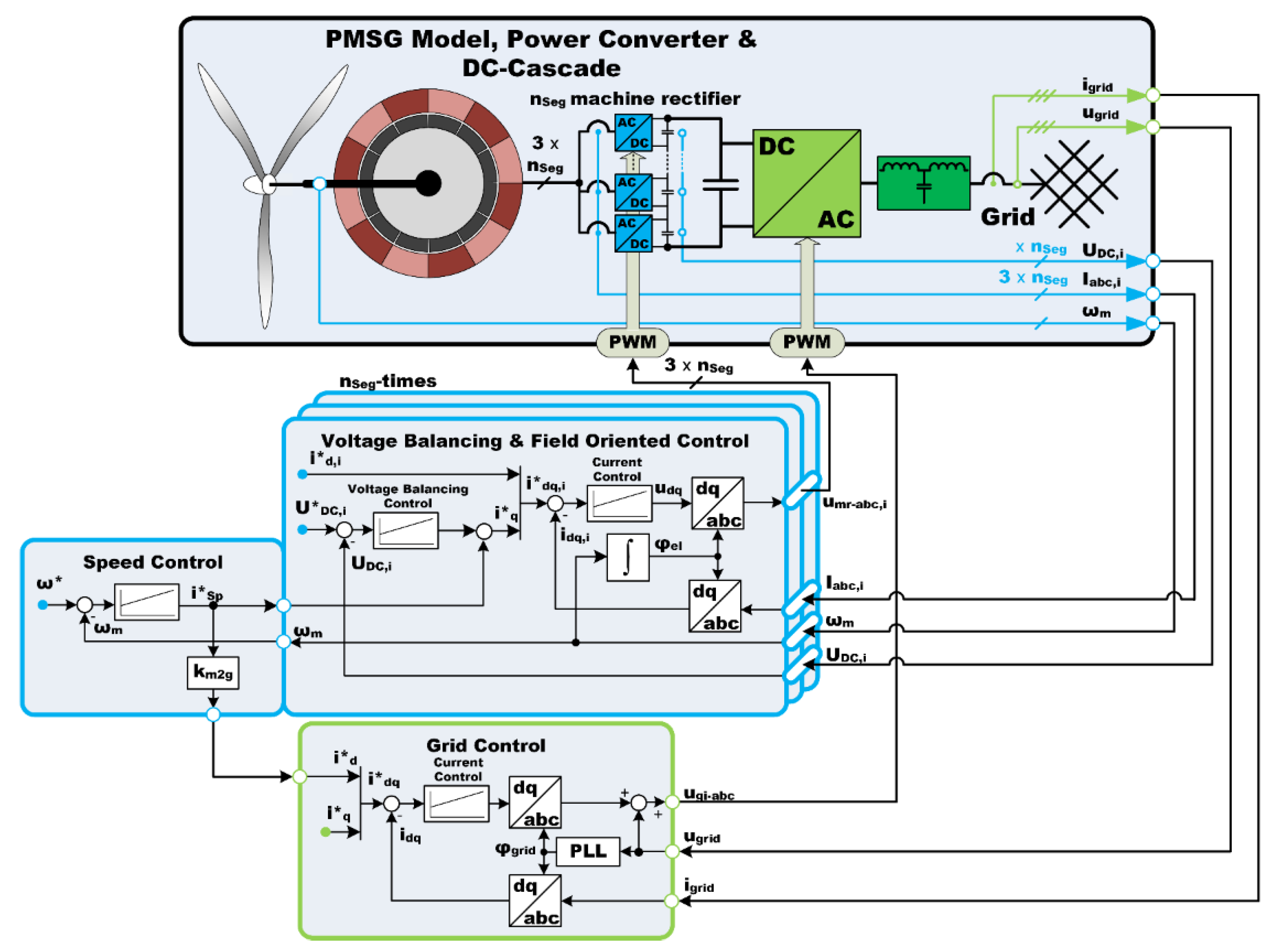
2. DC-Cascade Formed by Interconnected Power Rectifiers

The key to achieving a medium DC voltage is the interconnection of the power rectifier system. The segment rectifiers are connected in series to increase the intermediate DC voltage. Commercially available 690 V three-phase two-level rectifiers [5,6,7,8] reach intermediate voltages of U DC = 1.1   kV and a maximum voltages of U DC   m a x = 1.2   kV . When two rectifiers are connected in series on the DC-side, the intermediate voltage doubles to U DC = 2.2   kV . With 48-segment rectifiers various combinations of parallel and series connections are available, they form the DC-cascade. The intermediate DC voltage can be adjusted via the configuration of the DC-cascade. The configuration also affects the complexity and redundancy of the power rectifier system. Figure 2 shows an example of a DC-cascade in the configuration S12P4. With the 48-segment rectifier, 12 in series and 4 in parallel connected, the intermediate voltage results to U DC   H V = 13.2   kV .
The direct connection of the generator segments with the individual power rectifiers are shown, as well as the series and parallel connection of the DC-cascade. The DC-cascade is coupled to the intermediate link and can be further connected to a DC grid or a medium voltage AC/DC converter. Figure 2 as well shows that there is a galvanic coupling due to the direct connection between the segments and the rectifier. Grounding the middle point of the DC intermediate link halves the required rated insulation voltage of the insulation system. The entire generator and rectifier insulation must withstand half of the intermediate circuit voltage plus the peak value of the modulated segment AC voltage to ground [37].
U N   I n s u l a t i o n = 1 2 U DC + U p e a k   A C
Table 1 summarizes the possible configuration of the DC-cascade with 48 segments. The theoretical maximum of the DC voltage for the introduced generator with 48 series segments is reached at U DC   H V   M a x = 57.6   kV . The nominal voltage at this configuration can be assumed to be U DC   H V   n o m . = 52.8   kV . To control fluctuations in power transmission, the range between the nominal and maximum voltage is necessary. However, the best efficiency is achieved at the nominal voltage. In state-of-the-art WECS, all rectifiers are connected in parallel and the nominal intermediate voltage results to U DC = 1.1   kV .
To simplify the power rectifier system, the parallel rectifiers can be combined into one equivalent rectifier, reducing the number of rectifiers to one for each parallel branch of the DC-cascade. Considering that ~10 rectifier stacks are used in state-of-the-art multi MW WECS [2,4,5,6,7,8,9], and 12 rectifier stacks are also used in the S12P4 configuration to form the DC-cascade, the power rectifier effort is comparable. The configuration of the DC-cascade can be seen as a compromise between reliability, complexity and the desired level of intermediate voltage.
The DC-cascade causes a combination of the high DC voltage and the low segment AC voltage as insulation voltage. The insulation system of generator and power rectifier must isolate the mixed AC/DC voltage. At the market, available low voltage power rectifier does not meet the requirements to withstand the mixed AC/DC voltage. The insulation design of the cascaded power rectifier must be adapted, quite similar to topologies used in HVDC applications, to withstand the medium mixed AC/DC voltage [38,39,40]. The insulation of the generator must also be adapted for medium voltage. Nevertheless, the mass and thus the economic efficiency of the generator strongly depends on the realization of the insulation system.

3. Control of the DC-Cascade

As in many drive applications, field-oriented control (FOC) is used as the basis for controlling the presented PMSG with DC-cascade. The standard d-q-model which was chosen to describe the generators system model, is derived from the Park’s transformation of the stator currents as described in [41,42]. The stator voltages u d and u q of the machine can be described by (4) and (5).
u d = R i d + L d d i d d t ω e l L q i q
u q = R i q + L q d i q d t + ω e l ( L d i d + ψ P M )
In (4) and (5) R is the stator resistor, L d , q the stator inductance in the d q axis, ω e l the electrical velocity and ψ P M magnetic flux introduced by the permanent magnets. With the number of poles, p , the electromagnetic torque, T e l , generated by the machine can be defined as follows:
T e l = 3 2 p ( i q ψ q i d ψ d )
= 3 2 p ( i q ψ P M + ( L d L q ) i d i q )
The angular speed of the PMSG can concluded from the mechanical load torque T m and the inertia J of the drive system. The torque by the friction is neglected in this step.
ω m = 1 J ( T e l T m ) d t
The classic FOC and the PMSG with the state of the art power converter system are described in [14,43]. The speed controller with the underlying FOC is used to control the machine rectifier. Standard three-phase current control as described in [44] is used for the grid inverter. The machine currents i a b c , the grid currents i G r i d   a b c , the intermediate voltage u d c and the machine speed ω m are fed back to the controller as measured values. The machine rectifier and the grid inverter are driven via PWM from the control. The machine rectifier is directly connected to the terminals of the generator. The grid inverter is connected to the machine rectifier via the intermediate link and coupled to the grid. The converter system of the PMSG ensure an energy exchange between the generator and the grid.
As the investigated generator is segmented and is operated by a distributed control, thus the Equations (4) and (5) are calculated for each segment and Equation (6) must be extended to calculate the total electrical torque [14].
T e l = 3 2 p ψ P M i = 0 n S e g i q , i
In addition, the DC-cascade also influences the used system model and control system. The DC link voltage u DC , i of each series-connected machine rectifier or capacitor is calculated by its differential equation, using the initial voltage u DC   0 , i , the current i DC , i and the capacitance C DC , i .
u DC , i = u DC   0 , i + 1 C DC , i i DC , i d t
The total intermediate link voltage u DC is the result of the sum of the individual DC voltages for each of the n S e g segments.
u DC = i = 0 n S e g u DC , i
The capacitor current i DC , i is calculated by the currents introduced by the grid inverter i DC   G r i d and the machine rectifier i DC   S e g , i .
i DC , i = i DC   G r i d i DC   S e g , i
As the total intermediate link is a sum of several independent voltages, a balancing control is needed to ensure the same value of each voltage u DC , i . The voltage balancing control adjusts the setpoint for the machine current i q   S P , i . The series connected rectifier, balancing control and PMSG are shown as a block diagram in Figure 3.
The FOC remains the same as before, but is implemented once for each series connected rectifier and supplemented by the voltage controller. The voltage controller, which was previously responsible for the complete intermediate voltage, is no longer required. However, the speed controller remains as the central controller. A setpoint torque for the FOC and a setpoint current for the grid inverter control are generated. This controller structure ensures an individual voltage control of all series connected machine rectifiers with simultaneous speed control of the generator.
The control and structure of the DC-cascade was tested in a simple laboratory setup, using two machine rectifiers connected in series, a power DC source as the current source, and, for simplicity, a stator inductivity and resistor to represent the electrical machine. A flexible control unit is used to operate each rectifier individually. Fiber optic communication is established between the rectifiers to provide real-time communication and control of the test setup. An observer PC with MATLAB/Simulink in external mode is used to run the test setup. Figure 4a shows a schematic of the laboratory setup and Figure 4b a photo of the laboratory setup.
The current source feeds a constant current while the machine rectifiers maintain a constant voltage across the DC-cascade. The rectifier control unit measures the stator current i a b c , i and the DC voltage u DC , i , which are used for the control and recorded for the analysis. For further analysis, an oscilloscope also measures the DC currents i DC , i and the DC voltages u DC , i . The control, DC-cascade configuration and the dynamic behavior were tested at different operating points. Figure 5 shows a voltage setpoint step from u DC , i = 200   V to u DC , i = 300   V . Figure 5a displays the values recorded by the control unit. Figure 5b shows the measured values from the oscilloscope. Since the experimental setup uses resistors, that can only be used as load, the energy flows from the current source to the resistors. The behavior is the reverse of that in a generator. Due to the energy flow, the voltages of the DC-cascade increase, when the current i a b c , i of the segments is reduced. Immediately after the setpoint change from u DC , i = 200   V to u DC , i = 300   V , the currents i a b c , i and i q from the machine rectifiers are reduced. The current i q , i is limited at zero, since the resistors are only acting as load and thus a negative i q current is not possible. Despite the current limitation, the voltages u DC , 1 and u DC , 2 follow the setpoint step and the voltages reach a steady state after t = 150   ms . An additional setpoint step from u DC , i = 100   V to u DC , i = 150   V at lower load is shown in Figure 6, where (a) the control unit records and (b) the oscilloscope records are shown. Analyzing the sequence of Figure 6 shows that the dynamic and overall behavior is similar to the results of Figure 5 [45].
The test setup shows that the distributed control algorithm works for the simple setup and can maintain a constant voltage on the DC-cascade. Furthermore, different voltage setpoint steps and disturbances such as different load currents could be tested satisfactorily.

4. Preliminary Design of the Generator

Various design constraints are taken into account when dimensioning the generator. The basic or main boundary conditions result from the application and the used wind turbine. Table 2 presents the main design constraints of the PMSG. The main constraints are independent of the proposed topology and commonly used for the design of a WECS generator [11,12].
When designing the generator, two essential aspects of the medium voltage concept must be taken into account. The first aspect is the calculation of the copper fill factor, which decreases with increasing voltage, as thicker voltage insulation is required. The voltage insulation material also acts as thermal insulation; therefore, increasing the insulation material in the slot makes it more difficult to maintain a permissible temperature in the winding. Determining the permissible power dissipation is the second important design challenge. In the design, the rated segment voltage U Seg is slightly adjusted to 675 V, which leads to a change in the coil current.
The rated electrical power of the generator P N is defined by the mechanical power P mech and the efficiency η by
P N = η P mech = 3 U N I N c o s φ N .
The total rated current of the generator is
I N = η P mech 3 U N c o s φ N .
The actual coil current is a fraction of the total stator current, the number of parallel coils per segment a Seg and number of segments n Seg
I coil = I N a Seg n Seg .
The current density J eff is the fraction of the current and the cross section of one conductor A L
J eff = I coil A L .
The cross section of one conductor A L is for a form-wound winding with a rectangular conductor
A L = b L h L + (   π 4 ) · r L 2
with conductor width b L and conductor height h L . By the standard IEC 60317-0-2 [46] the radius of the edges r L is parameterized. The number of conductors in a slot z n is twice the number of turns of a coil w coil . The fraction of the surface area of the copper A Cu and the cross sectional area of the slot A slot result to the copper fill factor κ Cu [47]
κ Cu = A Cu   A slot   .
During the design process, it is necessary to determine the tooth height   h z , the copper fill factor κ Cu , the power factor c o s   φ N , the efficiency η and the flux density of the spatial fundamental B ^ p . Several iterations are used to adjust these parameters during the design process. The pole pitch, active length and the number of slots are constant, so that the number of turns can be estimated by
w coil = J eff I coil A L z n 2 = J eff I coil b slot h slot 2 κ Cu .
This equation also shows a problem in principle. Changing the current density without changing the coil current leads to a higher winding factor or requires changes in the slot size. Increasing the winding factor while maintaining the slot size leads to smaller conductor surfaces, which significantly increases copper losses without considering the influence of the winding factor on the voltage. In terms of conductor insulation, a higher winding factor leads to a reduction in the copper fill factor. The behavior of the winding factor as a function of the tooth height and the current density is shown in Figure 7.
For this purpose, the tooth height is increased with regard to a good fit of the conductor in the slots, in order to keep the height of a conductor smaller than 8 mm because of proximity effects. With the number of turns and the given slot dimensions, it is possible to estimate the dimensions of the conductors. It is important to define the number of conductors arranged side by side and on top of each other in a slot. Sufficiently small proximity effects are achieved if the height of the conductor is chosen to be smaller than the conductor width. The different distances in the slots should be taken into account when calculating the dimensions [1]. The copper fill factor of the stator slot is calculated using the conductor and slot dimensions with
κ Cu = A L   w coil b slot 2 h z .
The output torque of a permanent magnet generator with surface magnets is given to
T = A ^ p B ^ p V
with the electric loading, the flux density and the bore volume according to [11]. The known geometrical machine dimensions and the thickness of the permanent magnets result in the bore volume and the flux density. The calculation of the spatial fundamental of the electric loading can be done by
A ^ p = 2 ξ p 2 w coil   I coil τ N 1
where τ N 1 is the slot pitch and ξ p is the winding factor for the fundamental. Using Table 2, the rated torque can be determinate by
T N =   P N     2   π   n N 10   MNm .
The torque calculated with Equation (21) must match the desired torque in Equation (23). By adjusting the tooth height and core length, the electric loading can be influenced and also the bore volume. Table 3 shows some basic design parameters of the generator, which are not changed in the following investigation.

5. Design Methods of a Wind Generator Respecting the Voltage Level

In previous studies, a current density in the stator slots of J 1 = 5 A mm 2 was found to be a good compromise between machine mass, power factor and efficiency [10,11]. The Equation (21) shows the dependence of the electric loading to the current density. Equation (23) indicates that without changing the main design conditions, the same electrical load is required in each design to achieve the same rated output power. The following shows that this can best be achieved by adjusting the tooth height. This influences the active mass and the power factor. If the current density is decreased, the power factor decreases and the mass increases due to the necessary longer tooth length. From this point of view, a high current density is desirable. A higher current density causes the wire to heat up and imposes higher requirements on the cooling systems. In the following investigation, the design of a low voltage and a medium voltage generator is compared for different current densities J 1 =   2 ,   3 ,   4 ,   5 and 6 A mm 2 .
Figure 8b shows the percentage losses of the ring generator. Due to its special design, the iron losses are very low compared to the main losses, the I2R losses of the winding. The losses are also influenced by the operating temperature, which requires a high degree of knowledge about the thermal behavior of the winding.
Figure 8c shows the linear behavior of the winding resistance versus temperature assuming a constant current. Thus, with a temperature increase of 100 K, the resistance increases by ~30% and likewise the I2R losses, which in turn increases the temperature depending on the thermal insulation of the winding system. Therefore, the design process shown in Figure 8a is used to couple the electromagnetic design with the thermal design. In Figure 8d the mass of the designs are shown. The design of the rotor remains the same. The active mass of the rotor is assumed to be m r o t o r = 15.1   t for all designs.
Using the design process presented for the different current densities and voltage levels, the design parameters shown in Table 4 are calculated. Table 4 demonstrates the design parameters as a function of current density, voltage level and the influence of the different voltage levels on the copper fill factor. This leads to disadvantages in the tooth height and the power factor. It can be seen that a low current density requires higher teeth, which leads to a higher active mass.
For validation and further calculations, the machines are modeled in the FEM software FEMAG-DC. A separate model is created for each current density. Figure 9a shows the general model considering the different insulations and with modeled conductors in the coils. Depending on the investigation, a simpler layout without modeling the conductors but considering the calculated copper fill factor is sufficient. The flux density distribution for such a model is shown in Figure 9b.

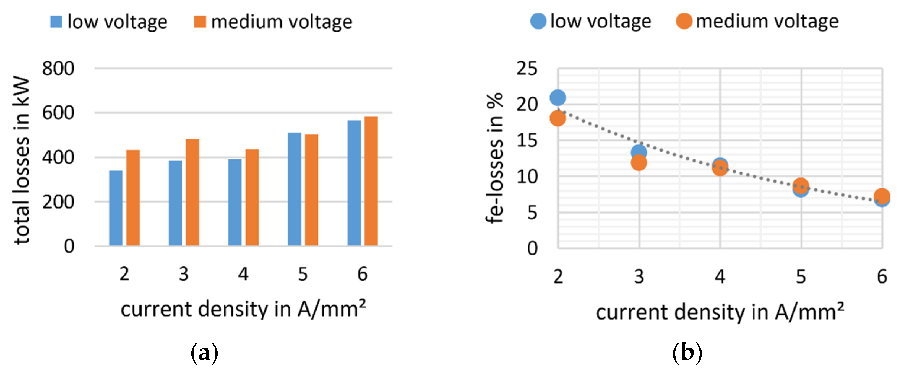
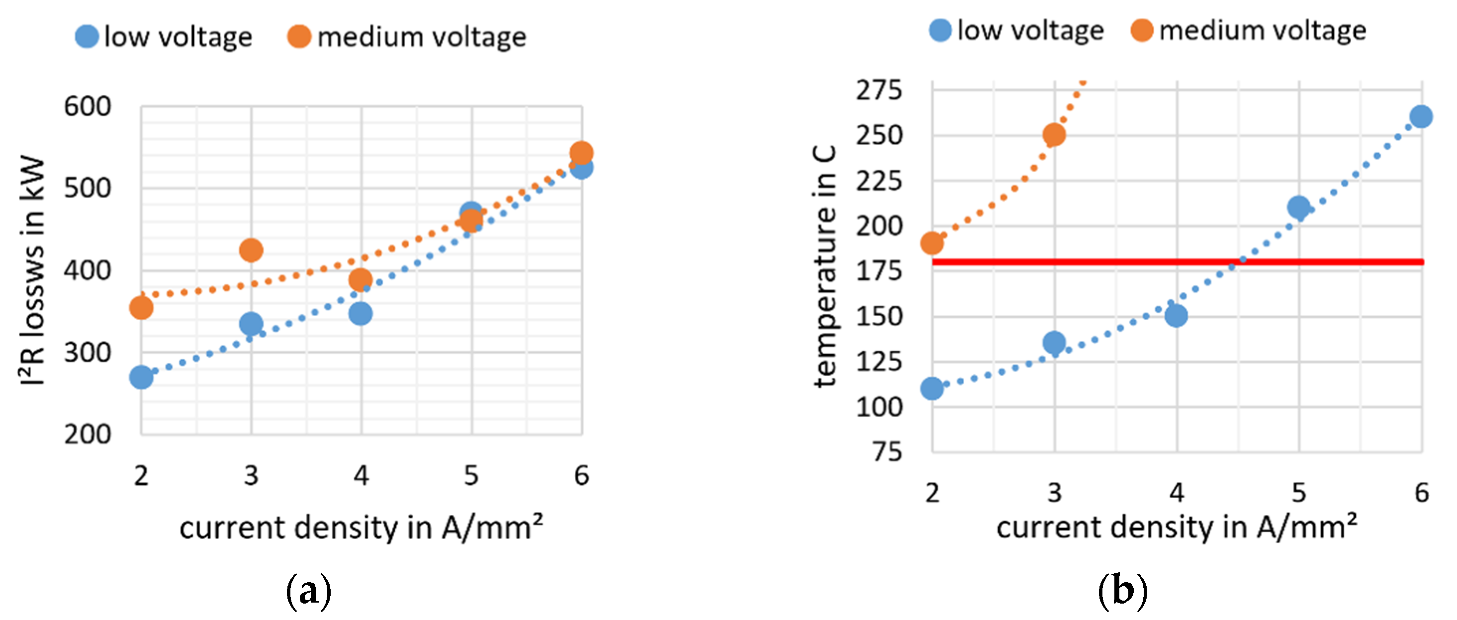
6. Thermal Behavior and Design Evaluation

Figure 10a visualizes the tooth height of the configurations listed in Table 4. A configuration with higher current density is designed using a smaller tooth height. Figure 10b shows the power factor of these configurations and it demonstrates the increase of the power factor when the tooth height is reduced.
Figure 11a presents the total iron losses of the stator and the rotor for different current density configurations. As explained earlier, a lower current density is compensated with a higher tooth height, which explains an increase in iron losses. There is also an overall decrease in the percentage of total losses, which is shown in Figure 11b. Since all the designs achieve the same electric loading in the stator, there is no need to modify the rotor design, so permanent magnet losses are not considered in this investigation. In addition to the generator losses, there are also the losses of the rectifier and converter system. By simulating the machine rectifier and grid converter at the rated operating point in a back-to-back configuration, the power losses were determined to be P L C o n = 213.7   kW . The rectifier and converter losses are unaffected by the chosen current density. For the medium DC voltage design in a DC network, only the rectifier losses are considered, which further reduces the losses.
Overall, this demonstrates the advantages of using a high current density. To find an optimum for this configuration, the thermal behavior must be taken into account. Thus, a prediction of the winding temperature is necessary. MATLAB/Simulink is used to simulate a thermal circuit diagram that considers radial and axial heat transfer to the outside of the machine. The outside surface of the machine is cooled down by air convection.
The main source of heat are the winding losses. The I2R losses of the stator winding are visualized in Figure 12a. At a higher current density, the influence of the thicker insulation is reduced for the medium voltage design. The losses are calculated at 120 °C, so they do not take into account the thermal behavior of the overall design. Increasing the current density from 2 A/mm2 to 3 A/mm2 increases the I2R losses by ~60 kW, which has a significant effect on the temperature. Figure 12b shows a quadric increase in temperature with the current density. It shows that the low voltage design can operate up to 4–5 A/mm2 without an active cooling system. Even at 2 A/mm2, the medium voltage concept temperature is already with 180 °C above the usual valid maximum temperature of the standard wire insulations.

7. Conclusions

This study shows how a higher voltage can be achieved at the intermediate voltage circuit of a segmented PMSG through the DC-cascade design of power rectifiers. Several segment power rectifiers connected in series are used to generate a medium output voltage. The voltage balancing control of the DC-cascade was presented and it was shown that balancing is possible with the control. The laboratory setup verifies the function of the control. The configuration of the DC-cascade is used to adjust different intermediate voltages. For direct driven WECS, this concept could be an alternative to the used standard topologies. With this approach, the generator and rectifier insulation system must be able to withstand the full mixed AC/DC voltage to ground, even though each stator segment has a low rated output voltage of 675 V. Furthermore, the PMSG design process for a medium voltage generator is shown and the dimensioning of the insulation layers with their consequences for the generator design at different current densities is discussed. Further, a way to design this concept is disclosed and their consequences for the overall design is discussed. It is shown that the medium voltage design of a generator becomes more demanding. The adjustment of the tooth height resulting in a lower power factor, a small increase of the mass and especially the demands on the cooling system increases. Therefore, a thermal analysis is carried out for the machine concepts and the effect to the winding temperature is discussed. The insulation stress under mixed AC/DC voltage needs to be investigated in more detail and the overall dimensioning of the generator insulation should also be reconsidered. Furthermore, the interconnection of many WECS in a wind farm with a DC grid or a medium voltage grid inverter will be investigated in the future. Further research will focus on direct liquid cooling, the insulation design of the generator for mixed AC/DC voltages and the subsequent power transfer in the wind farm or grid.

Author Contributions

Conceptualization, J.S., S.L., M.J., B.P., M.H.G., A.S., M.K., K.S. (Klaus Schleicher) and K.S. (Klaus Schäfer); Formal analysis, J.S.; Methodology, J.S., S.L., M.J., B.P., M.H.G., A.S., M.K., K.S. (Klaus Schleicher) and K.S. (Klaus Schäfer); Validation, S.L., M.J., B.P., M.H.G., A.S., M.K., K.S. (Klaus Schleicher) and K.S. (Klaus Schäfer); Writing—original draft, J.S. and S.L.; Writing—review and editing, J.S., S.L. and M.J. All authors have read and agreed to the published version of the manuscript.

Funding

The authors would like to thank the German Federal Ministry for Economic Affairs and Energy as well as the Project Coordinator Jülich for funding the research project Magnetring III (support code 0324276A) leading to this article. Only the authors are responsible for the content of this publication.

Institutional Review Board Statement

Not applicable.

Informed Consent Statement

Not applicable.

Data Availability Statement

Not applicable.

Conflicts of Interest

The authors declare no conflict of interest.

References

  1. Steffen, J.; Lengsfeld, S.; Jung, M.; Ponick, B.; Herranz Gracia, M.; Spagnolo, A.; Schleicher, K.; Schaefer, K. Design of a Medium Voltage Generator and Power Converter for High Power Wind Energy Conversion Systems. In Proceedings of the 2020 55th International Universities Power Engineering Conference (UPEC), Torino, Italy, 1–4 September 2020; pp. 1–5. [Google Scholar] [CrossRef]
  2. Yaramasu, V.; Wu, B.; Sen, P.C.; Kouro, S.; Narimani, M. High-power wind energy conversion systems: State-of-the-art and emerging technologies. Proc. IEEE 2015, 103, 740–788. [Google Scholar] [CrossRef]
  3. Blaabjerg, F.; Ma, K. Wind energy systems. Proc. IEEE 2017, 105, 2116–2131. [Google Scholar] [CrossRef] [Green Version]
  4. Rohrig, K.; Berkhout, V.; Callies, D.; Durstewitz, M.; Faulstich, S.; Hahn, B.; Jung, M.; Pauscher, L.; Seibel, A.; Shan, M.; et al. Powering the 21st century by wind energy—Options, facts, figures. Appl. Phys. Rev. 2019, 6, 31303. [Google Scholar] [CrossRef]
  5. Technical Information ModSTACK™ HD; 6MS20017E43W38170 Datasheet; Infineon: Neubiberg, Germany, 2012.
  6. Application Guide LV7000 Drives; GEK133481 Datasheet; GE: Boston, MA, USA, 2015.
  7. Semistack® Renewable Energy; SKS B1 090 GD 69/11-MA PB Datasheet; Semikron: Nürnberg, Germany, 2013.
  8. Semistack RE; Flyer Semistack RE; Semikron: Nürnberg, Germany, 2019.
  9. Carmeli, M.S.; Castelli-Dezza, F.; Marchegiani, G.; Mauri, M.; Rosati, D. Design and analysis of a Medium Voltage DC wind farm with a transformer-less wind turbine generator. In Proceedings of the XIX International Conference on Electrical Machines—ICEM 2010, Rome, Italy, 6–8 September 2010; pp. 1–6, ISBN 978-1-4244-4174-7. [Google Scholar]
  10. Stuebig, C.; Haberjan, L.; Seibel, A.; Steffen, J.; Thalemann, F.; Wecker, M.; Ponick, B. Segmented permanent magnet ring generator with active damping of axial oscillations. In Proceedings of the 2016 XXII International Conference on Electrical Machines (ICEM), SwissTech Convention Center, Lausanne, Switzerland, 4–7 September 2016; IEEE: Piscataway, NJ, USA, 2016; pp. 564–570, ISBN 978-1-5090-2538-1. [Google Scholar]
  11. Stuebig, C.; Seibel, A.; Schleicher, K.; Haberjan, L.; Kloepzig, M.; Ponick, B. Electromagnetic design of a 10 MW permanent magnet synchronous generator for wind turbine application. In Proceedings of the IEEE International Electric Machines and Drives Conference (IEMDC), Coeur d’Alene Resort, Coeur d’Alene, ID, USA, 11–13 May 2015; pp. 1202–1208, ISBN 978-1-4799-7941-7. [Google Scholar]
  12. Bak, C.; Zahle, F.; Bitsche, R.; Kim, T.; Yde, A.; Henriksen, L.C.; Hansen, M.H.; Blasques, J.P.A.A.; Gaunaa, M.; Natarajan, A. Description of the DTU 10 MW reference wind turbine. In Proceedings of the Danish Wind Power Research 2013, Fredericia, Denmark, 27–28 May 2013. [Google Scholar]
  13. Steffen, J.; Seibel, A.; Wecker, M. Proofing the concept of a lightweight generator for high power wind applications in a test bench. In Proceedings of the 16th Wind Intergation Workshop, Berlin, Germany, 25–27 October 2017. [Google Scholar]
  14. Seibel, A.; Stübig, C.; Wecker, M.; Steffen, J.; Nielebock, S.; Kandasamy, K.; Mertens, A. Distributed control of a multi-pole permanent magnet synchronous generator for wind turbine application. In Proceedings of the 18th European Conference on Power Electronics and Applications (EPE’16 ECCE Europe), Karlsruhe, Germany, 5–8 September 2016; Volume 18. [Google Scholar] [CrossRef]
  15. Heron, C.; Catlett, R.; Siplin, D. Medium-Voltage Motor Optimization: Two Ways to Choose Cost-Effective ac Machines. IEEE Ind. Appl. Mag. 2020, 26, 40–47. [Google Scholar] [CrossRef]
  16. Lilla, A.D.; Dehnavifard, H.; Khan, M.A.; Barendse, P. Optimization of high voltage geared permanent-magnet synchronous generator systems. In Proceedings of the 2014 XXI International Conference on Electrical Machines (ICEM), Berlin, Germany, 2–5 September 2014; pp. 1356–1362, ISBN 978-1-4799-4389-0. [Google Scholar]
  17. Zhao, J.; Liu, Y.; Xu, X. Comparisons of Concentrated and Distributed Winding PMSM in MV Power Generation. In Proceedings of the 2018 XIII International Conference on Electrical Machines (ICEM), Alexandroupoli, Greece, 3–6 September 2018; Volume 92018, pp. 2437–2443, ISBN 978-1-5386-2477-7. [Google Scholar]
  18. Abu-Rub, H.; Holtz, J.; Rodriguez, J.; Baoming, G. Medium-Voltage Multilevel Converters—State of the Art, Challenges, and Requirements in Industrial Applications. IEEE Trans. Ind. Electron. 2010, 57, 2581–2596. [Google Scholar] [CrossRef]
  19. Zhao, C.; Dujic, D.; Mester, A.; Steinke, J.K.; Weiss, M.; Lewdeni-Schmid, S.; Chaudhuri, T.; Stefanutti, P. Power Electronic Traction Transformer—Medium Voltage Prototype. IEEE Trans. Ind. Electron. 2014, 61, 3257–3268. [Google Scholar] [CrossRef]
  20. Shuai, P.; Biela, J. Design and optimization of medium frequency, medium voltage transformers. In Proceedings of the 2013 15th European Conference on Power Electronics and Applications (EPE), Lille, France, 2–6 September 2013; pp. 1–10, ISBN 978-1-4799-0116-6. [Google Scholar]
  21. Zhang, P.; Du, Y.; Habetler, T.G.; Lu, B. A Survey of Condition Monitoring and Protection Methods for Medium-Voltage Induction Motors. IEEE Trans. Ind. Appl. 2011, 47, 34–46. [Google Scholar] [CrossRef]
  22. Haq, S.U.; Jayaram, S.H.; Cherney, E.A. Insulation Problems in Medium-Voltage Stator Coils Under Fast Repetitive Voltage Pulses. IEEE Trans. Ind. Appl. 2008, 44, 1004–1012. [Google Scholar] [CrossRef]
  23. Paoletti, G.J.; Golubev, A. Partial discharge theory and technologies related to medium-voltage electrical equipment. IEEE Trans. Ind. Appl. 2001, 37, 90–103. [Google Scholar] [CrossRef]
  24. Wheeler, J. Effects of converter pulses on the electrical insulation in low and medium voltage motors. IEEE Electr. Insul. Mag. 2005, 21, 22–29. [Google Scholar] [CrossRef]
  25. Stübig, C.; Seibel, A.; Steffen, J.; Wecker, M.; Shan, M.; Thalemann, F.; Haberjan, L.; Kucka, J.; Krämer, J.; Schleicher, K.; et al. Abschlussbericht: MAGNETRING II: Aufbau eines Ringgenerators mit Aktiver Luftspaltregelung unter Laborverhältnissen FKz; 0325502A; Fraunhofer-Institut für Windenergie und Energiesystemtechnik (IWES): Kassel, Germany, 2017. [Google Scholar]
  26. Kouro, S.; Rodriguez, J.; Wu, B.; Bernet, S.; Perez, M. Powering the Future of Industry: High-Power Adjustable Speed Drive Topologies. IEEE Ind. Appl. Mag. 2012, 18, 26–39. [Google Scholar] [CrossRef]
  27. Zhu, Z.Q.; Hu, J. Electrical machines and power-electronic systems for high-power wind energy generation applications: Part II—Power electronics and control systems. COMPEL 2012, 32, 34–71. [Google Scholar] [CrossRef]
  28. Kouro, S.; Malinowski, M.; Gopakumar, K.; Pou, J.; Franquelo, L.G.; Wu, B.; Rodriguez, J.; Pérez, M.A.; Leon, J.I. Recent Advances and Industrial Applications of Multilevel Converters. IEEE Trans. Ind. Electron. 2010, 57, 2553–2580. [Google Scholar] [CrossRef]
  29. Bueno, E.J.; Cobreces, S.; Rodriguez, F.J.; Hernandez, A.; Espinosa, F. Design of a Back-to-Back NPC Converter Interface for Wind Turbines with Squirrel-Cage Induction Generator. IEEE Trans. Energy Convers. 2008, 23, 932–945. [Google Scholar] [CrossRef]
  30. Li, J.; Huang, A.Q.; Bhattacharya, S.; Jing, W. Application of active NPC converter on generator side for MW direct-driven wind turbine. In Proceedings of the 2010 Twenty-Fifth Annual IEEE Applied Power Electronics Conference and Exposition (APEC), Palm Springs, CA, USA, 21–25 February 2010; Volume 022010, pp. 1010–1017, ISBN 978-1-4244-4782-4. [Google Scholar]
  31. Blaabjerg, F.; Liserre, M.; Ma, K. Power Electronics Converters for Wind Turbine Systems. IEEE Trans. Ind. Appl. 2012, 48, 708–719. [Google Scholar] [CrossRef] [Green Version]
  32. Parker, M.A.; Ng, C.; Ran, L. Fault-Tolerant Control for a Modular Generator–Converter Scheme for Direct-Drive Wind Turbines. IEEE Trans. Ind. Electron. 2011, 58, 305–315. [Google Scholar] [CrossRef] [Green Version]
  33. Zhang, L.; Cai, X. A Novel Multi-level Medium Voltage Converter Designed for Medium Voltage Wind Power Generation System. In Proceedings of the Power and Energy Engineering Conference (APPEEC), 2010 Asia-Pacific, Chengdu, China, 28–31 March 2010; pp. 1–4, ISBN 978-1-4244-4812-8. [Google Scholar]
  34. Zhang, Y.; Yuan, X.; Al-Akayshee, M. A Reliable Medium-Voltage High-Power Conversion System for MWs Wind Turbines. IEEE Trans. Sustain. Energy 2020, 11, 859–867. [Google Scholar] [CrossRef]
  35. Yuan, X.; Chai, J.; Li, Y. A Transformer-Less High-Power Converter for Large Permanent Magnet Wind Generator Systems. IEEE Trans. Sustain. Energy 2012, 3, 318–329. [Google Scholar] [CrossRef]
  36. Acharya, S.; Hazra, S.; Vechalapu, K.; Bhattacharya, S. Medium voltage power conversion architecture for high power PMSG based wind energy conversion system (WECS). In Proceedings of the ECCE, 2017 IEEE Energy Conversion Congress and Exposition, Cincinnati, OH, USA, 1–5 October 2017; pp. 3329–3336, ISBN 978-1-5090-2998-3. [Google Scholar]
  37. Kaufhold, M.; Schäfer, K.; Bauer, K.; Rossmann, R. Medium and high PDSs—Requirements and suitability proof for winding insulation systems. INSUCON Birm. 2006, 10, 86–92. [Google Scholar]
  38. Akagi, H. Multilevel converters: Fundamental circuits and systems. Proc. IEEE 2017, 105, 2048–2065. [Google Scholar] [CrossRef]
  39. Perez, M.A.; Bernet, S.; Rodriguez, J.; Kouro, S.; Lizana, R. Circuit topologies, modeling, control schemes, and applications of modular multilevel converters. IEEE Trans. Power Electron. 2015, 30, 4–17. [Google Scholar] [CrossRef]
  40. Schneider, H.M.; Allaire, J.F.; Lips, H.P.; Olavarria, E.V.; Ong, T.L.; Richens, F.; Vancers, I.; Wehling, R.J.; Wu, C.T. Insulation of HVDC converter stations. IEEE Trans. Power Deliv. 1999, 14, 387–392. [Google Scholar] [CrossRef]
  41. Park, R.H. Two-reaction theory of synchronous machines generalized method of analysis-part I. Trans. Am. Inst. Electr. Eng. 1929, 48, 716–727. [Google Scholar] [CrossRef]
  42. Drobnič, K.; Gašparin, L.; Fišer, R. Fast and Accurate Model of Interior Permanent-Magnet Machine for Dynamic Characterization. Energies 2019, 12, 783. [Google Scholar] [CrossRef] [Green Version]
  43. Liu, C.; Yixiao, L. Overview of advanced control strategies for electric machines. Chin. J. Electr. Eng. 2017, 3, 53–61. [Google Scholar] [CrossRef]
  44. Teodorescu, R.; Liserre, M.; Rodriguez, P. Grid Converters for Photovoltaic and Wind Power Systems; Wiley: Chichester, West Sussex, UK, 2011; ISBN 978-0-470-05751-3. [Google Scholar]
  45. Dürr, P. Untersuchung des Generator-Umrichter-Systems einer Multi-MW-Windenergieanlage mit DC-Kaskade zur Erhöhung der Zwischenkreisspannung. Master’s Thesis, Leibniz University Hanover, Hanover, Germany, 2020. [Google Scholar]
  46. International Electrotechnical Commission. Specifications for Particular Types of Winding Wires: Part. 0–2: General Requirements—Enamelled Rectangular Copper Wire; International Electrotechnical Commission: Genf, Switzerland, 2013; IEC 60317-0-2. [Google Scholar]
  47. Müller, G.; Vogt, K.; Ponick, B. Berechnung Elektrischer Maschinen; Völlig Neu Bearb. 6. Auflage; Wiley-VCH: Weinheim, Germany, 2012; ISBN 3527660194. [Google Scholar]
Figure 1. Scaled down low voltage demonstration generator.
Energies 14 03106 g001
Figure 2. DC-cascade in the configuration S12P4.
Energies 14 03106 g002
Figure 3. Extended Control of the PMSG with DC-cascade balancing control.
Energies 14 03106 g003
Figure 4. (a) Schematic of the laboratory test setup; (b) Picture of the laboratory test setup.
Energies 14 03106 g004
Figure 5. Voltage setpoint change from 200 V to 300 V at 10 A load condition; (a) Control unit recordings; (b) Oscilloscope recordings.
Energies 14 03106 g005
Figure 6. Voltage setpoint change from 100 V to 150 V at 5 A load condition; (a) Control unit recordings; (b) Oscilloscope recordings.
Energies 14 03106 g006
Figure 7. Winding factor depending on tooth height and current density.
Energies 14 03106 g007
Figure 8. (a) Design process of the medium voltage generator; (b) Percentage losses in the generator; (c) Resistance of the winding depending on temperature; (d) The active mass of the stator.
Energies 14 03106 g008
Figure 9. (a) FEMAG-DC model considering to the insulation; (b) The flux density distribution calculated by FEMAG-DC.
Energies 14 03106 g009
Figure 10. (a) Tooth height depending to the current density; (b) Behavior of the power factor depending to the current density.
Energies 14 03106 g010
Figure 11. (a) Total iron losses depending to the current density; (b) Percentage iron losses to the total losses.
Energies 14 03106 g011
Figure 12. (a) I2R losses at 120 degree winding temperature in the stator winding; (b) Thermal behavior of the winding respecting the losses.
Energies 14 03106 g012
Table 1. DC-Cascade Configuration.
DC-Cascade ConfigurationIntermediate Voltage in kVRated Insulation Voltage (Peak to Ground) in kV
SeriesParallelNominal VoltageMaximum VoltageAC/DC Mixed Voltage
1481.11.21.6
2242.22.42.2
3163.33.62.8
4124.44.83.4
686.67.24.6
868.89.65.8
12413.214.48.2
16317.619.210.6
24226.428.815.4
48152.857.629.8
Table 2. Main Design Constraints of the PMSG.
Design Constraints of the PMSG
ParameterSymbolValueUnit
Rated power P N 10MW
Rated rotor speed n N 10min−1
Rotor diameter D 15m
Efficiency @ P N η N >93%
No. of stator segments n Seg 48-
Rated segment voltage U Seg   N 690/675V
Air gap length δ ~15mm
No. of pole pairsp144-
No. of winding holesq0.5
Winding designTooth coil winding
Table 3. Design parameters of the PMSG.
Design Parameters of the PMSG
ParameterSymbolValueUnit
No. of slotsN432-
Thickness of the permanent magnets h PM 45mm
Slot width b slot 55mm
Stator yoke height h J 1 35mm
Rotor yoke height h J 2 60mm
Table 4. Overview of the different design parameters depending on the current density.
Current Density in A/mm2Tooth Height in mmCopper Fill FactorPower Factor
Low VoltageMedium VoltageLow VoltageMedium VoltageLow VoltageMedium Voltage
21741960.750.670.780.76
31111320.740.650.860.83
4891030.710.620.880.86
575830.690.590.890.88
662760.660.580.900.88
Publisher’s Note: MDPI stays neutral with regard to jurisdictional claims in published maps and institutional affiliations.

