Article

Common-Mode Voltage Harmonic Reduction in Variable Speed Drives Applying a Variable-Angle Carrier Phase-Displacement PWM Method

by
Abraham Marquez Alcaide
1,*,†,
Vito Giuseppe Monopoli
2,†,
Xuchen Wang
3,†,
Jose I. Leon
1,4,†,
Giampaolo Buticchi
3,†,
Sergio Vazquez
1,†,
Marco Liserre
5,† and
Leopoldo G. Franquelo
1,4,†
1
Electronic Engineering Department, Universidad de Sevilla, 41004 Sevilla, Spain
2
Department of Electrical and Information Engineering, Politecnico di Bari, 70126 Bari, Italy
3
Zhejiang Key Laboratory on the More Electric Aircraft Technologies, University of Nottingham Ningbo China, Ningbo 315100, China
4
Department of Control Science and Engineering, Harbin Institute of Technology, Harbin 150001, China
5
Power Electronics Department, Christian-Albrechts Universität zu Kiel, 24118 Kiel, Germany
*
Author to whom correspondence should be addressed.
These authors contributed equally to this work.
Energies 2021, 14(10), 2929; https://doi.org/10.3390/en14102929
Submission received: 6 April 2021 / Revised: 4 May 2021 / Accepted: 5 May 2021 / Published: 19 May 2021

Abstract

:
Electric variable speed drives (VSD) have been replacing mechanic and hydraulic systems in many sectors of industry and transportation because of their better performance and reduced cost. However, the electric systems still face the issue of being considered less reliable than the mechanical ones. For this reason, researchers have been actively investigating effective ways to increase the reliability of such systems. This paper is focused on the analysis of the common-mode voltage (CMV) generated by the operation of the VSDs which directly affects to the lifetime and reliability of the complete system. The method is based on the mathematical description of the harmonic spectrum of the CMV depending on the PWM method implementation. A generalized PWM method where the carriers present a variable phase-displacement is developed. As a result of the presented analysis, the CMV reduction is achieved by applying the PWM method with optimal carrier phase-displacement angles without any external component and/or passive filtering technique. The optimal values of the carrier phase-displacement angles are obtained considering the minimization of the CMV total harmonic distortion. The resulting method is easily implementable on mostly off-the-shelf mid-range micro-controller control platforms. The strategy has been evaluated in a scaled-down experimental setup proving its good performance.

1. Introduction

Power converters are widely used in all energy scenarios such as motor drives, renewable energy sources integration, power quality applications, energy storage systems and efficient electrical transportation. From low- to high-power applications, grid-connected and stand-alone systems can be found [1]. As a general trend, the applications are moving forward from mechanical and/or hydraulic systems to electrical drives because of the increase in performance, pricing cutting, size and weight reduction and maintenance tasks simplification [2]. As a consequence, the variable-speed drive (VSD) actually plays one of the most important roles in the power electronics field.
Power electronics have gone through a huge development in the last few decades, especially in recent years. New power devices technologies, efficient power converter topologies as well as high-performance control and modulation strategies have emerged as a result of joint research between academia and industry [3,4,5]. As an example, multiple advanced multi-level topologies have been demonstrated as a good candidate for the motor drive application [6]. However, despite most of these new technologies being fully available, the industrial impact of these solutions by the industry is still limited. Either due to strict design requirements, limitations in system implementation, the required power and voltage levels or the slow implementation pace in the industry, the conventional three-phase two-level IGBT-based power converter is the most widely used topology in most of the industrial products. In Figure 1, the traditional scheme of a motor drive is represented including a three-phase two-level IGBT-based power converter. In Figure 1, the possible capacitive coupling to ground are also represented, which helps to develop a circuit to model the electrical behavior of the system.
The control and modulation techniques for VSDs have been well-known by industry and academia for decades and multiple options can be found in the literature [4]. The use of a power converter as VSD presents many advantages such as enhanced dynamic performance, high efficiency due to the accurate control of flux and current and improved system efficiency at partial loads [7]. From the modulation point of view, among the possible alternatives, the mainstream solution to operate the two-level VSD is to apply a pulse-width modulation (PWM) technique based on a bipolar PWM strategy per phase using only one high-frequency triangular carrier [3]. This PWM implementation is the simplest one being a straight-forward modulation method because most of available control platforms include dedicated hardware peripherals to deploy the PWM technique to generate the switching signals of the power semiconductors [8]. In Figure 2a, this traditional PWM method for a three-phase two-level power converter is shown.
Despite the advantages of power converters based on VSD, several drawbacks associated with the high-switching frequency affects to the performance and reliability of the system [9,10,11]. For instance, a conducted and radiated electromagnetic interference (EMI) is introduced. Additionally, the shaft voltage and bearing currents phenomenon for the electrical machines appear [12,13,14,15,16]. On the other hand, the common-mode voltage (CMV) generated by the VSD directly affects the reliability of the motor because of the degradation of the bearings. It has been reported that CMV is the main cause of the bearing degradation which represents more than 50% of the motor failures [9,10,17,18]. In order to face this issue, different mathematical approaches have been developed in order to estimate and to predict the early failure of these motor components [19,20,21,22]
Multiple solutions can be found in the literature regarding how to eliminate or mitigate the negative effects provoked by the inherent CMV created by the VSD operation to drive the machines. For instance, the introduction of the passive filters as well as active circuits for the CMV elimination have been explored by the academia [16,23,24,25,26,27,28]. In case of using passive elements filters, especially for high-power drives, the size and cost is increased. On the other hand, considering active common-noise canceler topologies, although good results are achieved the introduction of extra passive elements as well as power devices (and their auxiliary systems and drivers) are required. Therefore, both solutions increase the cost of the whole system, its complexity, volume and weight. On the other hand, the CMV mitigation by developing new modulation techniques has been also explored by the academia and industry. For instance, in [17,25,27,29,30,31,32] the proper switching patter selection based on space-vector modulation methods is proposed. Taking into account carrier-based PWM methods, as shown in Figure 2b, a PWM technique with three triangular carriers with phase-displacements equal to [ ϕ a , ϕ b , ϕ c ] = [ 0 , 120 , 240 ] was proposed in [33], where these carrier phase-displacement angles are found after an empirical trial and error method. In [34], an adaptive sampling time tri-carrier PWM was also proposed, where an effective CMV reduction is achieved for higher modulation indexes.
This paper provides a generalized analysis of the CMV harmonic spectrum generated during the operation of the VSD considering a PWM method with any carrier phase-displacement angles defined by [ ϕ a , ϕ b , ϕ c ] . In this work, the carrier phase-displacement angles are chosen considering the minimization of the whole CMV harmonic content. As a consequence of the analysis, the CMV harmonic distortion mitigation without using any external component and/or passive filtering technique is achieved. The proposed method is easily implementable on mostly off-the-shelf mid-range micro-controller control platforms.

2. Effect of the Common-Mode Voltage on the Motor Bearing Degradation

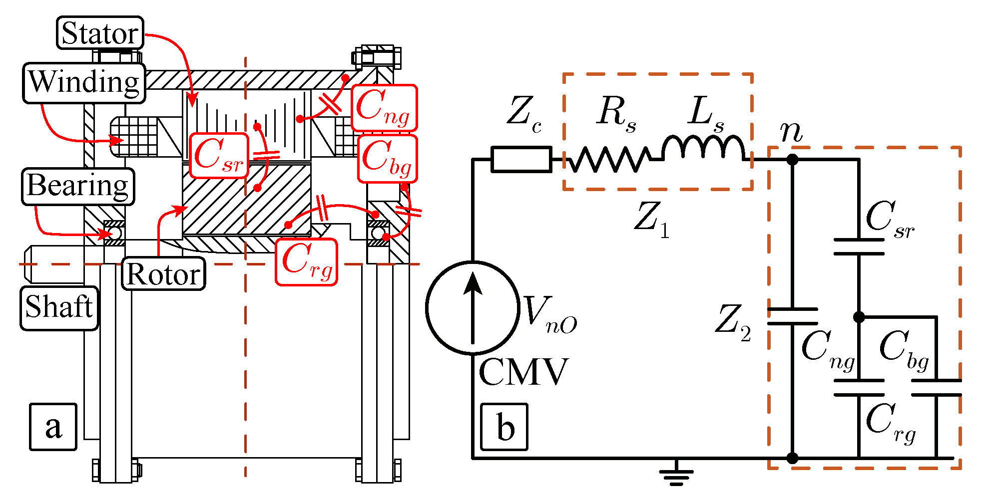
Figure 3a shows a section of a permanent-magnet synchronous machine (PMSM) highlighting the most important mechanical parts. Considering the bearing current effect caused by common-mode voltage (CMV) at neutral point of machine terminals (n), the machine can be modeled with a group of parasitic capacitors as shown in Figure 3b. The rotor shaft is capacitively coupled with the machine stator windings and stator frame, respectively. These capacitances act as a voltage divider, which leads to a rate of CMV on the rotor shaft [22]. While the shaft voltage exceeds the threshold voltage of greasing film (normally between 1.5 V and 30 V), the high dv/dt on the shaft will generate a high current pulse flowing from the bearing to the ground, which is regarded as the electric discharge machining (EDM) [11,20]. It has negative influence on the drive system with the resulting electromagnetic interference (EMI) and grounding failure. In addition, the bearing might be damaged by the circulating currents in the machine. Proper PWM techniques can be adopted to reduce the common-mode variations, which can avoid bearing failures and reduce the EMI [35].
As mentioned, in Figure 3b the common-mode equivalent circuit of the PMSM drive system is represented. In the figure, Z c is the common-mode impedance of the cable, and R s and L s are the stator winding resistance and stator winding inductance, respectively. To simplify the model, Z 1 is the equivalent common-mode impedance of R s and L s . Z 2 is the equivalent common-mode impedance of the stator-to-earth parasitic capacitance, which consists of the parasitic capacitance between stator and earth C n g , the parasitic capacitance between stator and rotor C s r , the parasitic capacitance betwe and earth C r g and the parasitic capacitance of bearing C b g .
The CMV of stator neutral point n can be calculated as
V n g = Z 2 Z c + Z 1 + Z 2 C M V
In the PMSM, the shaft voltage V b is expressed as
V b = C s r C s r + C r g + C b g V n g
Since the impedance Z x varies with the frequency, then the above equation can be expressed in the frequency domain as:
V n g ( ω ) = Z 2 ( ω ) Z c ( ω ) + Z 1 ( ω ) + Z 2 ( ω ) C M V ( ω ) = K · C M V ( ω )
Since factor K is constant, if CMV harmonic content is reduced, it is possible to mitigate the collateral effects in the generated V n g and as consequence in V b . In this way, the minimization of the CMV harmonic distortion represents a challenge to be overcome in order to extend the PMSM lifetime.

3. Common-Mode Voltage Harmonic Description in a Two-Level VSI Operating as a Motor Drive

The CMV of the power converter shown in Figure 1 is defined as the voltage between the neutral point in the load (n) and the middle point in the dc-link. It may happen that the neutral point n is not accessible to take the measurement and, therefore, the CMV can not be directly obtained. As an alternative, the CMV can be calculated as the summation of the phase voltages divided by the number of inverter phases as:
C M V = V n 0 = v a O + v b O + v c O 3
where v x O is the phase voltage between the phase x terminal and the point O (middle point of the dc-link).
In order to obtain an analytical expression of the CMV, a double Fourier series expression can be used, leading to:
x ( t ) = A 00 2 + n = 1 A 0 n cos ( n ω 0 t ) + B 0 n sin ( n ω 0 t ) + m = 1 n = 1 A m n cos ( m ω c + n ω 0 t ) + B m n sin ( m ω c + n ω 0 t )
where coefficients A 00 represents the average value and A 0 n and B 0 n represent the base-bands harmonic content. Coefficients A m n , B m n represent the side-bands harmonic content. All these coefficients are calculated using the double Fourier integral [3].
Considering the traditional single-carrier PWM modulation approach shown in Figure 2a, after the Fourier coefficients calculation, the phase voltage in a VSD can be described using the double Fourier series as:
v x O ( t ) = M x V d c 2 cos ( ω 0 t + θ x ) + 2 V d c π m = 1 n = 1 1 m J n m π 2 M x sin ( m + n ) π 2 cos ( m ( ω c t + ϕ x ) + n ( ω 0 t + θ x ) )
where M x and θ x are, respectively, the modulation index and the phase angle of phase x ( x = a , b , c ). J n ( z ) is the first kind Bessel function of z and order n.
In a generalized PWM strategy, a triangular carrier can be considered associated to each converter phase. In this way, as shown in Figure 3b, three carrier signals are considered, where ϕ x is the phase displacement of the carrier associated to phase x. It is important to notice that only the fundamental frequency as well as side-bands harmonic content appear because the base-band harmonics are canceled.
From (6), it is possible to calculate the magnitude of each side-band harmonic component of the phase voltage v x O as:
V x O ( m , n ) = 2 V d c m π J n m π 2 M x sin ( m + n ) π 2
From this result, each harmonic component of the CVM in the VSD can be directly evaluated applying (6) using the corresponding components in the phase voltages V x O ( m , n ) . Each harmonic order k can be defined as k = m R + n , where R = ω c / ω 0 . In addition, for the sake of simplicity, it can be considered that the modulation index of all the phases are equal ( M a = M b = M c = M ). As the phase voltages can be described using the equivalent Fourier coefficients and considering that ϕ a is fixed to 0, the side-band harmonic components of the CMV can described as
v n O ( m , n ) = C M V ( m , n ) = V d c 3 m π J n m π 2 M sin ( m + n ) π 2 1 + e j ( m ϕ b + n θ b ) + e j ( m ϕ c + n θ c ) e j ( m ω c + n ω 0 ) t + 1 + e j ( m ϕ b + n θ b ) + e j ( m ϕ c + n θ c ) e j ( m ω c + n ω 0 ) t
To illustrate this, a example of the CMV harmonic spectrum is represented in Figure 4 where the magnitude of each harmonic component has been represented following the notation given (8). This example has been illustrated considering that R = 21 . In this sense, in the first harmonic group ( m = 1 ) (and all odd harmonics groups) there are only side-bands with even values of n. Similarly, in the second harmonic group m = 2 (and all even harmonic groups) the side-bands present non-zero values with odd values of n.

4. Relation between the Generalized Carrier Phase-Displacement PWM Method and the CMV Harmonic Content

From the expressions introduced previously, it is clear that the CMV harmonic content highly depends on the carrier phase-displacement angles of the PWM method. From (8), and assuming the phase a as reference for convenience (i.e., ϕ a = 0 , θ a = 0 ), the magnitude of a generic harmonic component of the C M V ( m , n , ϕ b , ϕ c ) , considering M a = M b = M c = M , can be re-written as:
C M V ( m , n , ϕ b , ϕ c ) = V n O ( m , n , ϕ b , ϕ c ) = 2 A ( m , n ) P ( m , n , ϕ b , ϕ c )
where factors A ( m , n ) and P ( m , n , ϕ b , ϕ c ) are defined as:
A ( m , n ) = V d c 3 m π J n m π 2 M sin ( m + n ) π 2
P ( m , n , ϕ b , ϕ c ) = 3 + 2 cos ( m ϕ b + n θ b ) + 2 cos ( m ϕ c + n θ c ) + 2 cos ( m ϕ b + n θ b m ϕ c n θ c )
In order to find the values of the carrier phase-displacement angles ϕ b and ϕ c that guarantee the minimum magnitude for a specific harmonic component ( m , n ) , it is required to develop the analytical expressions of the partial derivatives with respect to ϕ b and ϕ c . It yields to:
V n O ( m , n , ϕ b , ϕ c ) ϕ b = A ( m , n ) ( 2 m sin ( m ϕ b + n θ b m ϕ c n θ c ) + 2 m sin ( m ϕ b + n θ b ) ) 3 + 2 cos ( m ϕ b + n θ b ) + 2 cos ( m ϕ c + n θ c ) + 2 cos ( m ϕ b + n θ b m ϕ c n θ c )
Then, forcing (12) to be equal to 0:
V n O ( m , n , ϕ b , ϕ c ) ϕ b = 0 ϕ b = 1 m m ϕ c 2 n θ b + n θ c 2 + k π ϕ c = 2 ( m ϕ b + n θ b ) n θ c + 2 k π m π + n θ c m
Analogously, the partial derivative respect to ϕ c and its solution can be obtained as:
V n O ( m , n ) ϕ c = A ( m , n ) ( 2 m sin ( m ϕ b + n θ b m ϕ c n θ c ) 2 m sin ( m ϕ c + n θ c ) ) 3 + 2 cos ( m ϕ b + n θ b ) + 2 cos ( m ϕ c + n θ c ) + 2 cos ( m ϕ b + n θ b m ϕ c n θ c )
V n O ( m , n ) ϕ c = 0 ϕ b = 2 ( m ϕ c + n θ c ) n θ b + 2 k π m ϕ c = 1 m m ϕ b 2 n θ c + n θ b 2 + k π
Particularizing both systems (13) and (15) for m = 1 , n = 0 (because it is the dominant harmonic component in the CMV harmonic spectrum) and θ b = 120 , θ c = 240 which represents the usual case in a three-phase system, it can be seen that both systems of equations achieve two stationary points where [ ϕ b , ϕ c ] is equal to [ 120 , 240 ] or [ 240 , 120 ] . It is important to notice that this result does not depend on the modulation index M.
This fact is also proven if expression (9) is represented particularized for the harmonic component described by m = 1 and n = 0 . As it is shown in Figure 5a, represented using MatLab by implementing the mathematical description of the harmonic components, the magnitude of this dominant harmonic component is zero in both stationary points ( [ ϕ b , ϕ c ] equal to [ 120 , 240 ] and [ 240 , 120 ] ) whereas it is maximum when the traditional PWM technique is used ( ϕ b = ϕ c = 0 ). Additionally, Figure 5b,c represent the values of expression (9) particularized for m = 1 and n = 2 , and m = 1 and n = 2 , respectively. As it is shown in both figures, the carrier phase-displacement angles that achieve the cancellation of the dominant harmonic component do not lead to the cancellation of all other harmonic components. As can be observed in Figure 5, depending on the carrier phase-displacement angles solution that is chosen ( [ ϕ b , ϕ c ] equal to [ 120 , 240 ] or [ 240 , 120 ] ), one of the harmonic components with m = 1 and n = ± 2 is zero but the other is maximum.
As a practical example to show this concept, assuming a modulation index equal to M = 0.8 and the traditional carrier phase-displacement angles [ ϕ a , ϕ b , ϕ c ] = [ 0 , 0 , 0 ] , the magnitude of the harmonic components V n O ( m , n , ϕ b , ϕ c ) are:
V n O ( 1 , 0 , 0 , 0 ) = A ( 1 , 0 ) P ( 1 , 0 , 0 , 0 ) = 0.1363 V d c · 3 = 40.89 V d c [ V ] V n O ( 1 , 2 , 0 , 0 ) = A ( 1 , 2 ) P ( 1 , 2 , 0 , 0 ) = 0.0366 V d c · 0 = 0 [ V ] V n O ( 1 , 2 , 0 , 0 ) = A ( 1 , 2 ) P ( 1 , 2 , 0 , 0 ) = 0.0366 V d c · 0 = 0 [ V ]
However, if the carrier phase-displacement angles are equal to [ ϕ a , ϕ b , ϕ c ] = [ 0 , 120 , 240 ] , it leads to:
V n O ( 1 , 0 , 120 , 240 ) = A ( 1 , 0 ) P ( 1 , 0 , 120 , 240 ) = 0.1363 V d c · 0 = 0 [ V ] V n O ( 1 , 2 , 120 , 240 ) = A ( 1 , 2 ) P ( 1 , 2 , 120 , 240 ) = 0.0366 V d c · 0 = 0 [ V ] V n O ( 1 , 2 , 120 , 240 ) = A ( 1 , 2 ) P ( 1 , 2 , 120 , 240 ) = 0.0366 V d c · 3 = 0.1098 V d c [ V ]
Summarizing, although the elimination of the dominant harmonic component ( m = 1 , n = 0 ) is performed by the PWM method with three carriers applying one of the available possible carrier phase-displacement solutions, the appearance of a side-band harmonic component located at another frequency is unavoidable. However, it is important to notice that this non-zeroed harmonic component presents a lower magnitude than the dominant harmonic component located at the frequency described with m = 1 and n = 0 .
Important Remark: It has to be noticed that the use of carrier phase-displacement angles in the PWM method equal to [ 0 , 120 , 240 ] is not new. In [33], these angles were applied in a PWM method achieving a reduction in the CMV. However it was not demonstrated if this solution is the best one to be chosen in order to achieve maximum CMV harmonic performance, which is the main objective of this work. In fact, during the work, it will be demonstrated that the solution proposed in [33] is not optimal in terms of CMV harmonic distortion reduction.

5. Proposed Generalized Carrier Phase-Displacement PWM Method to Improve the CMV Total Harmonic Distortion

In order to mitigate the negative CMV effect on the motor bearings, instead of eliminating one specific harmonic content in the CMV harmonic spectrum as proposed in [33], it is more convenient to consider the total harmonic distortion (THD) of the CMV respect to the dc level as figure of merit to be minimized by the application of carrier phase-displacement angles in the PWM method. In this way, the C M V T H D can be defined as:
C M V T H D = 2 V d c m = 1 N 1 n = j j C M V ( m , n , ϕ b , ϕ c ) 2
It is possible to determine the carrier phase-displacement angles in the PWM method that minimize the resulting C M V T H D . The angles can be obtained with an exhaustive search evaluating (18) applying all the possible values of the carrier phase-displacement angles for different values of the modulation index. This process has been carried out assuming a modulation index range from M = 0.1 to M = 1.15 and calculating (18) considering the first three harmonic groups ( m 3 ) with | n | 6.
Figure 6 shows the evaluation of C M V T H D with different discrete values of the modulation index. As can be observed from the obtained results, the C M V T H D generated by the VSD applying the PWM method with [ 0 , 120 , 240 ] carrier-phase displacement angles is minimum when the modulation index range between 0.3 and 1.15 . However, for low modulation index values, the minimum value of the C M V T H D is achieved with other carrier phase-displacement angles. This result represents an improvement of the method presented in [33], where the carrier-phase displacement angles equal to [ 0 , 120 , 240 ] are claimed to be always optimal in terms of the CMV mitigation. As a summary of the obtained results, the corresponding C M V T H D values are represented in Figure 7. In the figure, three different options are represented, taking into account the carrier phase-displacement angles in the PWM method. On one hand, the values obtained applying the PWM method with carrier phase-displacement angles equal to [ 0 , 0 , 0 ] are higher compared with the other methods. Applying the carrier phase-displacement angles equal to [ 0 , 120 , 240 ] achieves good results but the C M V T H D is not minimized in the whole modulation range. In order to achieve the minimum value of the C M V T H D it is required to apply variable-angle carrier phase-displacement angles in the PWM method. The optimal values of these angles to achieve the minimization of the C M V T H D depending on the modulation index are represented in Figure 8.

6. Experimental Results

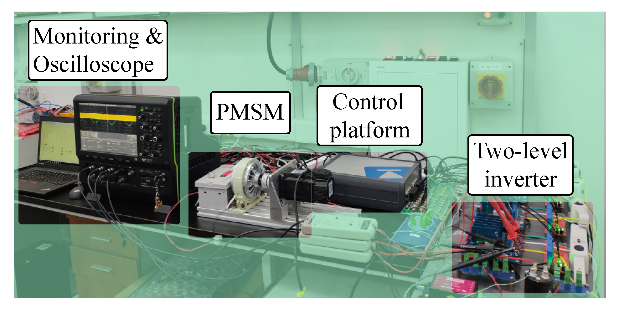
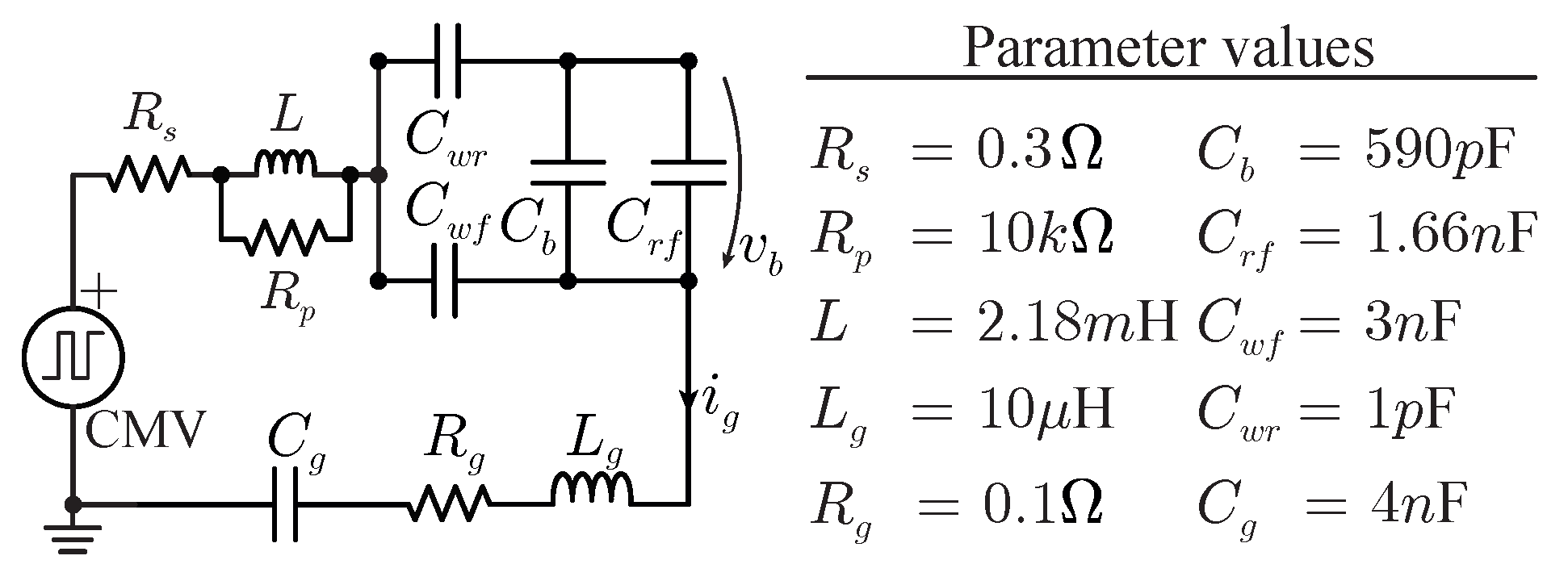
In order to check the effectiveness of the PWM techniques and to validate the CMV harmonic analysis performed in previous sections, the down-scaled laboratory experimental setup shown in Figure 9 has been used. The experimental prototype consists of a traditional three-phase two-level inverter connected to a 750 W three-phase PMSM with main parameters summarized in Table 1. On the other hand, the PMSM parasitic components are addressed in Figure 10. The controller and modulation schemes are implemented using the rapid prototyping real-time platform PLECS RT box [36].
Figure 11 shows the PMSM control and modulation strategies implemented in the experimental setup. In the control strategy, the PMSM is driven by a speed and current double closed control loop [37]. In the modulation stage, the three PWM methods ( [ ϕ a , ϕ b , ϕ c ] equal to [ 0 , 0 , 0 ] , [ 0 , 120 , 240 ] and [ 0 , ϕ b o p t , ϕ c o p t ] ) are tested to check the influence on the VSD CMV, the phase currents as well as the induced shaft voltage.
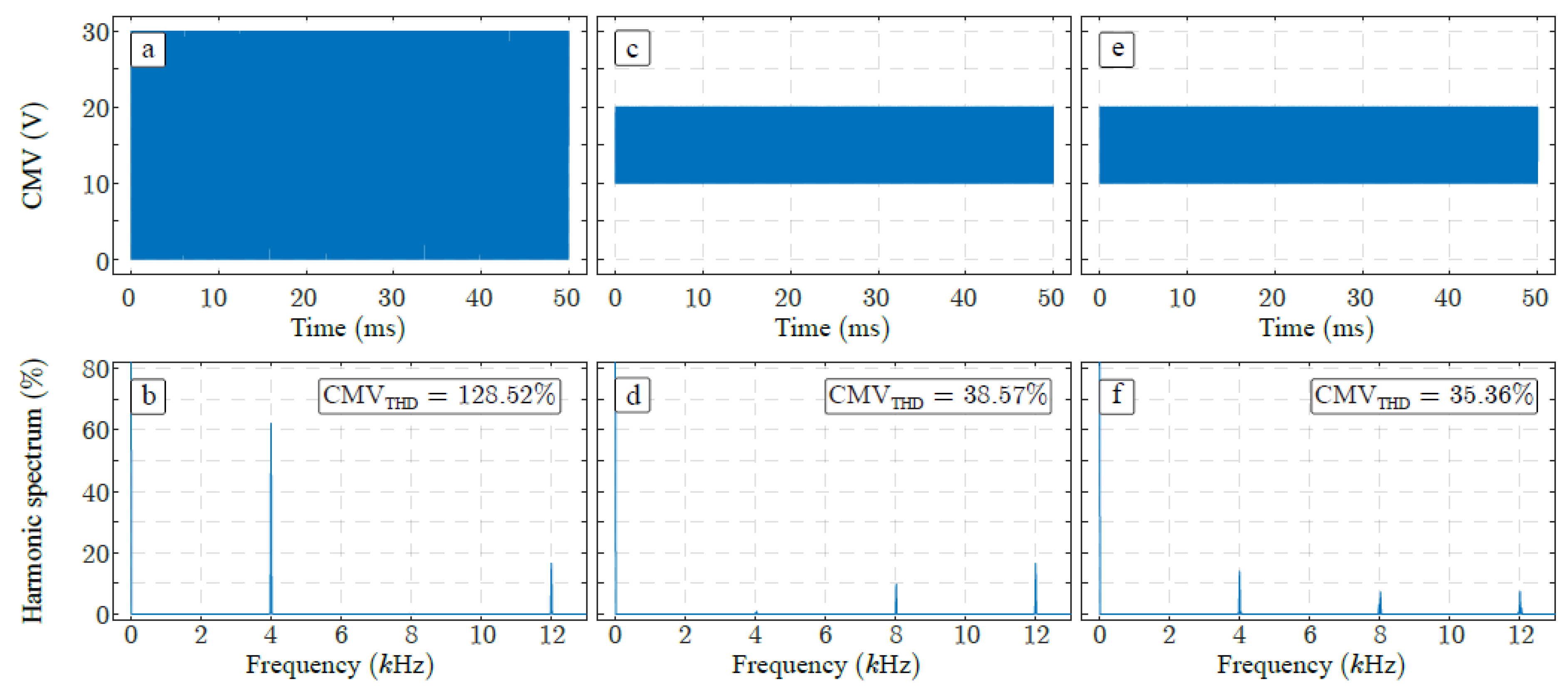
On one hand, the operation of the PMSM is analyzed in terms of the CMV generated by VSD applying the PWM method with the three set of carrier phase-displacement angles with f c = 4 kHz and rotational speed equal to 25 rpm, that corresponds to apply a modulation index equal to 0.2. As it can be observed, applying the carrier phase-displacement PWM technique with [ ϕ a , ϕ b , ϕ c ] equal to [ 0 , 120 , 240 ] , the peak-to-peak CMV and the C M V T H D are reduced compared with the single-carrier PWM method (see Figure 12c and Figure 12d, respectively). Applying this solution, the CMV harmonic content located at the switching frequency, that is m = 1 and n = 0 has been eliminated as expected. However, the non-negligible harmonic component shown in Figure 12d surrounding f c corresponds with coefficients m = 1 and n = 2 , what is expected from the analysis described in Figure 5. In order to minimize the C M V T H D , the optimal values of the carrier phase-displacement angles are applied and the corresponding results are summarized in Figure 12e,f. It can be observed that this solution also achieves a reduction of the peak-to-peak CMV but the C M V T H D is reduced as well compared with the previous PWM methods as it was expected observing Figure 6b.
In order to show another result, in Figure 13 is summarized the operation of the VSD applying the PWM method with [ ϕ a , ϕ b , ϕ c ] equal to [ 0 , 0 , 0 ] and [ 0 , 120 , 240 ] considering f c = 4 kHz, a speed reference equal to 250 rpm and a dc-link equal to 30 V. It is important to notice that this operational point corresponds to a modulation index equal to 0.84 and, therefore, (as it was addressed in Figure 7 and Figure 8) the optimal carrier phase-displacement angles are equal to the Kimball’s solution [33], that is [ 0 , 120 , 240 ] . From Figure 13, it is clear that the application of the optimal values of carrier phase-displacement angles leads to reduce both the peak-to-peak CMV and the C M V T H D . This experiment is also used to evaluate the operation of the PMSM in terms of the phase currents quality considering the PWM approaches. The results are reported in Figure 14. In Figure 14a the three-phase currents using the PWM method with [ ϕ a , ϕ b , ϕ c ] equal to [ 0 , 0 , 0 ] is shown. The harmonic spectrum of the phase a is represented in Figure 14b. In the same way, the three-phase currents as well as the harmonic spectrum of the phase a using the PWM technique with [ ϕ a , ϕ b , ϕ c ] equal to [ 0 , 120 , 240 ] are shown in Figure 14c and Figure 14d, respectively. As it can be observed, the harmonic distortion of the phase currents applying the PWM technique with optimal carrier phase-displacement angles experiences an increasing. The normalized i a current THD using the PWM method with [ ϕ a , ϕ b , ϕ c ] equal to [ 0 , 0 , 0 ] and [ 0 , 120 , 240 ] are 3.86 % and 4.86 % , respectively. However, it can be seen that the magnitude of this degradation is not significant because it is the range of miliamperes while the fundamental current component is 1.27 A.
These experiments have been carried out considering different operational conditions testing the performance of the methods with several angular speed values of the PMSM. The C M V T H D as well as the THD of the phase a current generated by the VSD are summarized in Table 2. It can be concluded that, using the PWM method with [ ϕ a , ϕ b , ϕ c ] equal to [ 0 , 120 , 240 ] , the CMV harmonic mitigation is significant. On the other hand, a slight degradation of the phase currents occurs but this drawback can be considered acceptable if the design parameters are defined by other constraints. Indeed, the inductance of the machine depends on the mechanical requirements and on the voltage/current rating, whereas the switching frequency usually has a lower limit due to the control bandwidth. For many applications in industrial drives, which present high value of the machine inductance, the increase in the current THD caused by applying the carrier phase-displacement angle PWM method would be negligible.
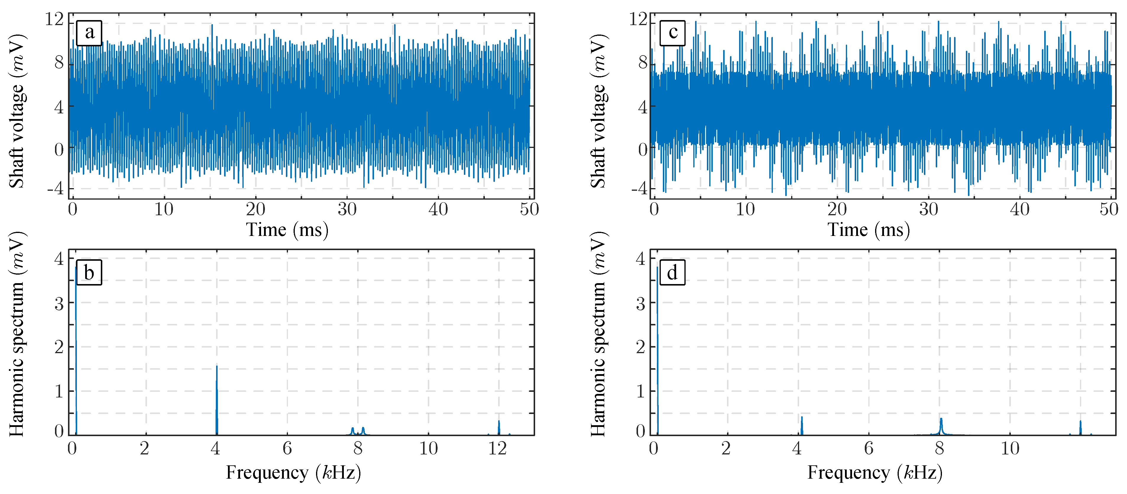
Finally, as it is mentioned in previous sections, the presence of high CMV in the VSD leads to the degradation of the motor bearing because of the corresponding high shaft voltages and leakage currents. The shaft voltage present in the system applying the PWM technique with [ ϕ a , ϕ b , ϕ c ] equal to [ 0 , 0 , 0 ] as well as those obtained applying [ 0 , 120 , 240 ] and [ 0 , ϕ b o p t , ϕ c o p t ] have been measured. The experimental results with rotational speed equal to 25 rpm and 250 rpm are represented in Figure 15 and Figure 16, respectively. As it can be observed from both experiments and their spectra, the shaft voltage has been reduced using the optimal carrier phase-displacement angles. This fact confirms that the use of this modulation method mitigates the motor bearings damage extending the machine lifetime.

7. Conclusions

Motor drives are essential players in the current power electronics and power system arena. The introduction of the VSDs was revolutionary because it meant a significant increase in performance and controllability of the power systems. However, as a major concern related to the VSDs operation, it has been demonstrated that the CMV deteriorates the motor bearings leading to a reduction of the machine lifetime.
This paper presents an analysis of a generalized PWM method with triangular carriers with phase-displacement angles in order to reduce the CMV harmonic content without the introduction of passive filtering elements and/or active devices for the canceler stage. An accurate mathematical model based on double Fourier series is provided to describe the CMV content. This mathematical description is used to determine the best carrier phase-displacement angles to reduce the CMV content. In the paper, it is demonstrated that, considering a three-phase voltage source inverter to operate as a motor drive, the use of three carriers with phase displacements equal to [ 0 , 120 , 240 ] is not always the best option in order to both reduce the low-frequency CMV harmonic components and also achieve the reduction of the CMV total harmonic distortion. For low values of the modulation index (up to 0.3) the optimal carrier phase-displacement angles are obtained, while applying [ 0 , 120 , 240 ] is the most proper solution for larger values of the modulation index.
The accuracy of the analysis and the effectiveness of the generalized carrier phase-displacement angle PWM method have been validated via experimental results in a down-scaled laboratory prototype.

Author Contributions

Conceptualization, A.M.A., J.I.L., V.G.M. and L.G.F.; methodology, A.M.A., V.G.M.; software, A.M.A.; validation, V.G.M., X.W. and S.V.; formal analysis, A.M.A., G.B., V.G.M.; resources, M.L. and L.G.F.; writing, original draft preparation, and writing, review and editing, all authors. All authors have read and agreed to the published version of the manuscript.

Funding

The authors gratefully acknowledge financial support provided by the Andalusian Government and the European Union under Projects P18-RT-1340 and SPARTAN-821381, respectively.

Conflicts of Interest

The authors declare no conflict of interest.

References

  1. Bose, B.K. Global Energy Scenario and Impact of Power Electronics in 21st Century. IEEE Trans. Ind. Electron. 2013, 60, 2638–2651. [Google Scholar] [CrossRef]
  2. Buticchi, G.; Bozhko, S.; Liserre, M.; Wheeler, P.; Al-Haddad, K. On-Board Microgrids for the More Electric Aircraft-Technology Review. IEEE Trans. Ind. Electron. 2019, 66, 5588–5599. [Google Scholar] [CrossRef] [Green Version]
  3. Holmes, D.G.; Lipo, T.A. Pulse Width Modulation for Power Converters: Principles and Practice; Wiley-IEEE Press: Hoboken, NJ, USA, 2003. [Google Scholar] [CrossRef]
  4. Yazdani, A.; Iravani, R. Voltage-Sourced Converters in Power Systems: Modeling, Control, and Applications; Wiley-IEEE Press: Hoboken, NJ, USA, 2010. [Google Scholar]
  5. Leon, J.I.; Kouro, S.; Franquelo, L.G.; Rodriguez, J.; Wu, B. The Essential Role and the Continuous Evolution of Modulation Techniques for Voltage-Source Inverters in the Past, Present, and Future Power Electronics. IEEE Trans. Ind. Electron. 2016, 63, 2688–2701. [Google Scholar] [CrossRef]
  6. Leon, J.I.; Vazquez, S.; Franquelo, L.G. Multilevel Converters: Control and Modulation Techniques for Their Operation and Industrial Applications. Proc. IEEE 2017, 105, 2066–2081. [Google Scholar] [CrossRef]
  7. Wilamowski, B.M.; Irwin, J.D. Power Electronics and Motor Drives; CRC Press: Boca Raton, FL, USA, 2017. [Google Scholar]
  8. Zhou, K.; Wang, D. Relationship between space-vector modulation and three-phase carrier-based PWM: A comprehensive analysis [three-phase inverters]. IEEE Trans. Ind. Electron. 2002, 49, 186–196. [Google Scholar] [CrossRef]
  9. Eaton, D.; Rama, J.; Hammond, P. Neutral shift [five years of continuous operation with adjustable frequency drives]. IEEE Ind. Appl. Mag. 2003, 9, 40–49. [Google Scholar] [CrossRef]
  10. Kalaiselvi, J.; Srinivas, S. Bearing Currents and Shaft Voltage Reduction in Dual-Inverter-Fed Open-End Winding Induction Motor With Reduced CMV PWM Methods. IEEE Trans. Ind. Electron. 2015, 62, 144–152. [Google Scholar] [CrossRef]
  11. Mutzw, A. Thousands of hits: On inverter-induced bearing currents, related work, and the literature. Elektrotechnik und Informationstechnik 2011, 128, 382–388. [Google Scholar] [CrossRef]
  12. Skibinski, G.L.; Kerkman, R.J.; Schlegel, D. EMI emissions of modern PWM AC drives. IEEE Ind. Appl. Mag. 1999, 5, 47–80. [Google Scholar] [CrossRef]
  13. Isomura, Y.; Yamamoto, K.; Morimoto, S.; Maetani, T.; Watanabe, A.; Nakano, K. Study of the Further Reduction of Shaft Voltage of Brushless DC Motor With Insulated Rotor Driven by PWM Inverter. IEEE Trans. Ind. Appl. 2014, 50, 3738–3743. [Google Scholar] [CrossRef]
  14. Jiang, D.; Chen, J.; Shen, Z. Common mode EMI reduction through PWM methods for three-phase motor controller. CES Trans. Electr. Mach. Syst. 2019, 3, 133–142. [Google Scholar] [CrossRef]
  15. Lee, S.; Park, J.; Jeong, C.; Rhyu, S.; Hur, J. Shaft-to-Frame Voltage Mitigation Method by Changing Winding-to-Rotor Parasitic Capacitance of IPMSM. IEEE Trans. Ind. Appl. 2019, 55, 1430–1436. [Google Scholar] [CrossRef]
  16. Han, Y.; Lu, H.; Li, Y.; Chai, J. Analysis and Suppression of Shaft Voltage in SiC-Based Inverter for Electric Vehicle Applications. IEEE Trans. Power Electron. 2019, 34, 6276–6285. [Google Scholar] [CrossRef]
  17. Hava, A.M.; Un, E. A High-Performance PWM Algorithm for Common-Mode Voltage Reduction in Three-Phase Voltage Source Inverters. IEEE Trans. Power Electron. 2011, 26, 1998–2008. [Google Scholar] [CrossRef]
  18. Muralidhara, B.; Ramachandran, A.; Srinivasan, R.; Reddy, M.C. Experimental measurement of shaft voltage and bearing current in an inverter fed three phase induction motor drive. In Proceedings of the 2011 3rd International Conference on Electronics Computer Technology, Kanyakumari, India, 8–10 April 2011; Volume 2, pp. 37–41. [Google Scholar] [CrossRef]
  19. Song-Manguelle, J.; Schröder, S.; Geyer, T.; Ekemb, G.; Nyobe-Yome, J. Prediction of Mechanical Shaft Failures Due to Pulsating Torques of Variable-Frequency Drives. IEEE Trans. Ind. Appl. 2010, 46, 1979–1988. [Google Scholar] [CrossRef]
  20. Magdun, O.; Binder, A. High-Frequency Induction Machine Modeling for Common Mode Current and Bearing Voltage Calculation. IEEE Trans. Ind. Appl. 2014, 50, 1780–1790. [Google Scholar] [CrossRef]
  21. Flieh, H.M.; Totoki, E.; Lorenz, R.D. Dynamic Shaft Torque Observer Structure Enabling Accurate Dynamometer Transient Loss Measurements. IEEE Trans. Ind. Appl. 2018, 54, 6121–6132. [Google Scholar] [CrossRef]
  22. Naik, R.; Nondahl, T.A.; Melfi, M.J.; Schiferl, R.; Wang, J.-S. Circuit model for shaft voltage prediction in induction motors fed by PWM-based AC drives. IEEE Trans. Ind. Appl. 2003, 39, 1294–1299. [Google Scholar] [CrossRef]
  23. Choochuan, C. A survey of output filter topologies to minimize the impact of PWM inverter waveforms on three-phase AC induction motors. In Proceedings of the 2005 International Power Engineering Conference, Singapore, 29 November–2 December 2005; Volume 2005, pp. 1–544. [Google Scholar] [CrossRef]
  24. Mei, C.; Balda, J.C.; Waite, W.P. Cancellation of common-mode Voltages for induction motor drives using active method. IEEE Trans. Energy Convers. 2006, 21, 380–386. [Google Scholar] [CrossRef]
  25. Di Piazza, M.C.; Tine, G.; Vitale, G. An Improved Active Common-Mode Voltage Compensation Device for Induction Motor Drives. IEEE Trans. Ind. Electron. 2008, 55, 1823–1834. [Google Scholar] [CrossRef]
  26. Fan, F.; See, K.Y.; Banda, J.K.; Liu, X.; Gupta, A.K. Investigation and mitigation of premature bearing degradation in motor drive system. IEEE Electromagn. Compat. Mag. 2019, 8, 75–81. [Google Scholar] [CrossRef]
  27. Jayaraman, K.; Kumar, M. Design of Passive Common-Mode Attenuation Methods for Inverter-Fed Induction Motor Drive With Reduced Common-Mode Voltage PWM Technique. IEEE Trans. Power Electron. 2020, 35, 2861–2870. [Google Scholar] [CrossRef]
  28. Tallam, R.M.; Kerkman, R.J.; Leggate, D.; Lukaszewski, R.A. Common-Mode Voltage Reduction PWM Algorithm for AC Drives. IEEE Trans. Ind. Appl. 2010, 46, 1959–1969. [Google Scholar] [CrossRef]
  29. Cacciato, M.; Consoli, A.; Scarcella, G.; Testa, A. Reduction of common-mode currents in PWM inverter motor drives. IEEE Trans. Ind. Appl. 1999, 35, 469–476. [Google Scholar] [CrossRef]
  30. Adabi, J.; Boora, A.A.; Zare, F.; Nami, A.; Ghosh, A.; Blaabjerg, F. Common-mode voltage reduction in a motor drive system with a power factor correction. IET Power Electron. 2012, 5, 366–375. [Google Scholar] [CrossRef]
  31. Espina, J.; Ortega, C.; de Lillo, L.; Empringham, L.; Balcells, J.; Arias, A. Reduction of Output Common Mode Voltage Using a Novel SVM Implementation in Matrix Converters for Improved Motor Lifetime. IEEE Trans. Ind. Electron. 2014, 61, 5903–5911. [Google Scholar] [CrossRef] [Green Version]
  32. Espina, J.; Ortega, C.; de Lillo, L.; Empringham, L.; Balcells, J.; Arias, A. Common-Mode Voltage Mitigation Technique in Motor Drive Applications by Applying a Sampling-Time Adaptive Multi-Carrier PWM Method. IEEE Access 2021, 9, 56115–56126. [Google Scholar] [CrossRef]
  33. Kimball, J.W.; Zawodniok, M. Reducing Common-Mode Voltage in Three-Phase Sine-Triangle PWM With Interleaved Carriers. IEEE Trans. Power Electron. 2011, 26, 2229–2236. [Google Scholar] [CrossRef]
  34. Alcaide, A.M.; Wang, X.; Yan, H.; Leon, J.I.; Monopoli, V.G.; Buticchi, G.; Vazquez, S.; Liserre, M.; Franquelo, L.G. Common-Mode Voltage Mitigation of Dual Three-Phase Voltage Source Inverters in a Motor Drive Application. IEEE Access 2021, 9, 67477–67487. [Google Scholar] [CrossRef]
  35. Shen, Z.; Jiang, D.; Liu, Z.; Ye, D.; Li, J. Common-Mode Voltage Elimination for Dual Two-Level Inverter-Fed Asymmetrical Six-Phase PMSM. IEEE Trans. Power Electron. 2020, 35, 3828–3840. [Google Scholar] [CrossRef]
  36. Plexim RT Box Rapid Prototype Platform. Available online: https://www.plexim.com/products/rt_box (accessed on 6 April 2021).
  37. Zheng, B.; Xu, Y.; Wang, G.; Yu, G.; Yan, H.; Wang, M.; Zou, J. Carrier frequency harmonic suppression in dual three-phase permanent magnet synchronous motor system. IET Electr. Power Appl. 2019, 13, 1763–1772. [Google Scholar] [CrossRef]
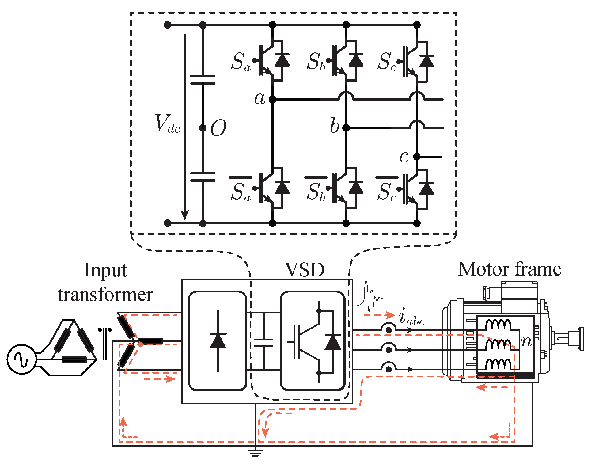
Figure 1. Traditional three-phase two-level converter for a motor drive application.
Energies 14 02929 g001
Figure 2. Modulation method of a three-phase two-level motor drive (a) Traditional PWM method with a single carrier (b) PWM technique with three carriers.
Energies 14 02929 g002
Figure 3. (a) PMSM machine section. (b) Equivalent impedance model of a PMSM machine.
Energies 14 02929 g003
Figure 4. Harmonic spectrum definition of the CMV.
Energies 14 02929 g004
Figure 5. Evaluation of the Equation (9) to evaluate V n O ( m , n , ϕ b , ϕ c ) considering (a) m = 1 , n = 0 (b) m = 1 , n = 2 (c) m = 1 , n = 2 .
Energies 14 02929 g005
Figure 6. Evaluation of the C M V T H D with different values of the modulation index (a) M = 0.1 (b) M = 0.2 (c) M = 0.3 (d) M = 0.4 (e) M = 0.5 (f) M = 0.6 (g) M = 0.7 (h) M = 0.8 (i) M = 0.9 (j) M = 1 (k) M = 1.1 (l) M = 1.15.
Energies 14 02929 g006
Figure 7. Evaluation of the C M V T H D with a modulation index range from 0.1 to 1.15 . (top) Conventional sigle-carrier PWM (bottom) Tricarrier PWM [33] and the Optimized PWM.
Energies 14 02929 g007
Figure 8. Carrier phase-displacement angles to achieve the minimization of the C M V T H D in a modulation index range from 0.1 to 1.15 .
Energies 14 02929 g008
Figure 9. Down-scaled 750 W three-phase PMSM laboratory prototype.
Energies 14 02929 g009
Figure 10. Parasitic components of the three-phase PMSM.
Energies 14 02929 g010
Figure 11. Controller scheme implemented in the experimental setup.
Energies 14 02929 g011
Figure 12. Results applying the traditional PWM method with [ ϕ a , ϕ b , ϕ c ] = [ 0 , 0 , 0 ] (a) CMV generated in the PMSM (b) CMV harmonic spectrum. Results applying the PWM method with [ ϕ a , ϕ b , ϕ c ] = [ 0 , 120 , 240 ] (c) CMV generated in the PMSM (d) CMV harmonic spectrum. Results applying the PWM method with [ ϕ a , ϕ b , ϕ c ] = [ 0 , ϕ b o p t , ϕ c o p t ] (e) CMV generated in the PMSM (f) CMV harmonic spectrum.
Energies 14 02929 g012
Figure 13. Results applying the traditional PWM method with [ ϕ a , ϕ b , ϕ c ] = [ 0 , 0 , 0 ] (a) CMV generated in the PMSM (b) CMV harmonic spectrum. Results applying the PWM method with [ ϕ a , ϕ b , ϕ c ] = [ 0 , 120 , 240 ] (c) CMV generated in the PMSM (d) CMV harmonic spectrum.
Energies 14 02929 g013
Figure 14. Results applying the traditional PWM method with [ ϕ a , ϕ b , ϕ c ] = [ 0 , 0 , 0 ] (a) Phase currents (b) Harmonic spectrum of phase a current. Results applying the PWM method with [ ϕ a , ϕ b , ϕ c ] = [ 0 , 120 , 240 ] (c) phase currents (d) Harmonic spectrum of phase a current.
Energies 14 02929 g014
Figure 15. PMSM shaft voltage with rotational speed equal to 25 rpm (corresponding modulation index 0.2) using the PWM method with carrier phase-displacement angles [ ϕ a , ϕ b , ϕ c ] equal to (a) [ 0 , 0 , 0 ] (c) [ 0 , 120 , 240 ] (e) [ 0 , ϕ b o p t , ϕ c o p t ] . (b,d,f) are their respective harmonic spectra.
Energies 14 02929 g015
Figure 16. PMSM shaft voltage with rotational speed equal to 250 rpm (corresponding modulation index 0.84) using the PWM method with carrier phase-displacement angles [ ϕ a , ϕ b , ϕ c ] equal to (a) [ 0 , 0 , 0 ] (c) [ 0 , ϕ b o p t , ϕ c o p t ] = [ 0 , 120 , 240 ] . (b,d) are their respective harmonic spectra.
Energies 14 02929 g016
Table 1. Multi-phase PMSM parameters.
ParametersValues
Winding resistance [ Ω ] 0.901
Winding inductance [mH] 6.552
Back-EMF coefficient K E [ V / rpm ] 0.0227
Moment of inertia J [ g / m 2 ] 0.12
Pole pair number4
Voltage [V]220
Nominal torque [Nm] 2.4
Nominal speed [rpm]3000
Table 2. C M V T H D and normalized THD of the phase a current considering up to 13 kHz using the PWM with [ ϕ a , ϕ b , ϕ c ] equal to [ 0 , 0 , 0 ] , [ 0 , 120 , 240 ] and [ 0 , ϕ b o p t , ϕ c o p t ] .
CMV THD [ % ] i a THD [ % ]
Speed [rpm]M [ p . u . ] [ 0 , 0 , 0 ] [ 0 , 120 , 240 ] [ 0 , ϕ b opt , ϕ c opt ] [ 0 , 0 , 0 ] [ 0 , 120 , 240 ] [ 0 , ϕ b opt , ϕ c opt ]
25 0.20 128.65 38.58 35.33 1.90 6.25 5.29
50 0.40 121.38 35.77 2.74 5.76
100 0.54 113.32 36.38 4.17 5.27
150 0.66 105.50 39.14 3.21 5.16
200 0.73 97.37 41.58 3.62 4.46
250 0.84 88.05 42.16 3.71 5.02
Publisher’s Note: MDPI stays neutral with regard to jurisdictional claims in published maps and institutional affiliations.