Article

Experimental Verification of Self-Adapting Data-Driven Controllers in Active Distribution Grids

by
Stavros Karagiannopoulos
1,2,*,
Athanasios Vasilakis
2,
Panos Kotsampopoulos
2,
Nikos Hatziargyriou
2,
Petros Aristidou
3 and
Gabriela Hug
1
1
EEH—Power Systems Laboratory, ETH Zurich, Physikstrasse 3, 8092 Zurich, Switzerland
2
School of Electrical and Computer Engineering, National Technical University of Athens, 15780 Athens, Greece
3
Department of Electrical Engineering, Cyprus University of Technology, Limassol 3036, Cyprus
*
Author to whom correspondence should be addressed.
Energies 2021, 14(10), 2837; https://doi.org/10.3390/en14102837
Submission received: 28 March 2021 / Revised: 24 April 2021 / Accepted: 4 May 2021 / Published: 14 May 2021

Abstract

:
Lately, data-driven algorithms have been proposed to design local controls for Distributed Generators (DGs) that can emulate the optimal behaviour without any need for communication or centralised control. The design is based on historical data, advanced off-line optimization techniques and machine learning methods, and has shown great potential when the operating conditions are similar to the training data. However, safety issues arise when the real-time conditions start to drift away from the training set, leading to the need for online self-adapting algorithms and experimental verification of data-driven controllers. In this paper, we propose an online self-adapting algorithm that adjusts the DG controls to tackle local power quality issues. Furthermore, we provide experimental verification of the data-driven controllers through power Hardware-in-the-Loop experiments using an industrial inverter. The results presented for a low-voltage distribution network show that data-driven schemes can emulate the optimal behaviour and the online modification scheme can mitigate local power quality issues.

1. Introduction and Related Work

Modern distribution system operators need to control Distributed Generators (DGs), such as Photovoltaic units (PV), wind turbines, and other distributed energy resources, such as battery energy storage systems and controllable loads, to guarantee safe grid operation, increase their operational flexibility or provide ancillary services to higher voltage levels. Centralised approaches based on optimal control of DGs usually require a communication, remote monitoring and control infrastructure, which current distribution networks (DN) lack due to high costs and complexity. On the other hand, local schemes offer communication-free, robust, cheap, but sub-optimal solutions which do not fully exploit the DG capabilities. Lately, data-driven control algorithms have been proposed, which use historical data, advanced off-line optimization techniques, and machine learning methods, to design local controls that emulate the optimal behaviour without the use of any communication [1,2,3,4].
The state-of-the-art data-driven schemes differ mainly in terms of two aspects. First, with respect to the existence of a feedback in the control method. Open-loop schemes, e.g., [2,4], do not use feedback, i.e., the DG output has no effect on the controller input variable. They are typically stable, and simple to implement. On the contrary, in closed-loop schemes, e.g., [1,3], the output of the controller has an impact on the local measurements and influences its input through a feedback term. These schemes are generally more complex to analyze in terms of stability. However, they can be more efficient in situations that are different from the ones in the training dataset [3]. The stability and convergence analysis of general local control schemes is investigated in [5]. The second differentiating characteristic is the number and type of local measurements and parameters used. They can rely only on one or on a set of measurements and parameters [1,2], such as local demand, generation and maximum inverter capacities. In the latter case, the set of measurements that best map the Optimal Power Flow (OPF) behaviour can be selected.
Nevertheless, the performance of the data-driven schemes proposed in the literature might degrade when the real-time conditions start drifting from the training dataset. The existing methods try to emulate the response seen in the training dataset which might be meaningless once the real-time conditions diverge, e.g., due to a topological change or an installation of a new unit. To tackle this problem, self-adapting algorithms for real-time operation should be considered.
Furthermore, most of the proposed control schemes have been analyzed only with digital simulations based on mathematical models of each system component. This approach provides high flexibility of system modelling and scenario testing at a much lower cost compared to hardware experiments. Nevertheless, modern power-electronic-based DGs are becoming more complex with behaviour that is difficult to capture in the mathematical models. This leads to the requirement for hardware or hardware-in-the-loop (HIL) experiments to safely validate the proposed controls. Such experimental verification of the data-driven controller real-time behaviour has not been addressed by existing works.
Conventional hardware testing is focused on the component-level, without considering the whole system. Compliance hardware tests described in standards and grid codes typically refer to open-loop schemes [6], where predetermined input signals are given to the Hardware-under-Test (HuT) in order to study its response. This can hide a lot of problematic issues since realistic implementations may require closed-loop analysis in order to examine the impact of the HuT on the whole system [7]. As the complexity of the devices increases in modern power systems, the conventional testing procedures may prove insufficient.
Hardware-in-the-Loop simulations offer a flexible testing platform both for research [8] and education [9], where physical equipment is incorporated into a simulated system. HIL simulations combine the best of both worlds, i.e., the flexible, scalable, low-cost, safe and user-friendly simulation environment with the realistic behaviour of a hardware device, resulting in conditions similar to a real implementation. Thus, the HuT is operated under realistic conditions and the simulated system is computed in real-time.
In Controller-Hardware-in-the-Loop (CHIL) simulations, the HuT is a hardware controller whereas in Power-Hardware-in-the-Ioop (PHIL) simulations, the HuT is a power device. The latter approach tests real hardware power devices, e.g., motors, DG inverters, or even a whole real microgrid, and may reveal hidden issues arising from time-delays or system dynamics. PHIL simulations consider the interactions between real power devices and simulated systems, allowing researchers to perform systems in addition to components testing.
The contributions of this paper is two-fold:
  • First, we propose a self-adapting algorithm for the data-driven controls to improve performance when the operating conditions are not as in the training dataset.
  • Second, we perform the first, to the best of our knowledge, experimental verification of data-driven local control schemes in inverter-based DGs to assess the performance of Artificial Intelligence (AI)-based controllers and identify hidden problems considering the whole system’s response, and not just individual components. Such an experimental verification in the power system society using control schemes that are allowed already today in grid codes i.e., volt/var schemes, can foster real-life field implementation.
The remainder of this paper is organised as follows. In Section 2, we summarise the off-line optimization approach to derive the optimal setpoints and the design of the data-driven local controllers that emulate the optimal response. Then, we present the proposed real-time self-adapting algorithm in Section 3. In Section 4, we present an overview of different testing levels for controllers and hardware, and in Section 5 the experimental results using the typical Cigre European Low Voltage (LV) grid. Finally, we draw conclusions in Section 6.

2. Data-Driven Control Design

In this section, we briefly review the process for designing the data-driven local controls. In short, a large number of off-line OPF calculations that consider various expected and critical operating conditions are used to derive rules that depend only on local measurements. This is achieved by machine learning algorithms that map the multi-dimensional space of the OPF setpoints into a reduced space based solely on local features. Thus, in real-time operation, no monitoring and communication infrastructure is required. Interested readers are referred to [1] for more details.
As input data, the grid topology and the installed capacity of the DGs and loads is needed, information that is usually available to the DN operators. As the topology is not always known, one can use topology identification based on the voltage sensitivities [10], and phase identification based on clustering approaches [11]. Thus, even in this situation, we would need an identification step and then the same method should be applied. In case of missing information, e.g., normalised solar radiation data of specific areas, typical load profiles, or the actual line/cable impedances, the operator can use default values from the literature. The impact of such sources of uncertainty can be examined and quantified.
Then, an OPF algorithm is used to process the data and derive the optimal DG behavior. Although any OPF formulation can be used, we present below a formulation from [1] based on the backward-forward sweep (BFS) power flow.

2.1. OPF Formulation

In this part, we present the single-phase formulation considering only DGs, e.g., PV units in the LV grid. The Distribution System Operator (DSO) guarantees safe grid operation by minimizing the system losses and operating costs while satisfying the power quality constraints. In this formulation, we penalise the curtailment of active power and the provision of reactive power support by DGs. The objective function is evaluated by considering the DG control cost over all network nodes N b , branches N b r and time horizon N O P F , i.e.,
min u t = 1 N OPF { j = 1 N b C P · P j , t c + C Q · Q j , t ctrl + i = 1 N br C P · P i , t loss } · Δ t
where u denotes the vector of the available active control measures and Δ t the length of each time period. The curtailed power of the DGs connected at node j and time t is calculated by P j , t c = P j , t g , max P j , t g , where P j , t g , max is the maximum available active power and P j , t g the actual active power injection of the DGs. The use of reactive power by the DGs connected at node j and time t is minimised, i.e.,  Q j , t ctrl = | Q j , t g | , where Q j , t g represents the reactive power injection or absorption. The cost of curtailing active power and providing reactive power support (opportunity cost or contractual agreement) is represented by the coefficients C P and C Q , respectively. Priority is given to the use of reactive power, i.e., we set C Q C P . Finally, the losses are calculated by P i , t loss = | I i , t br | 2 · R i br , where | I i , t br | is the magnitude of the current flow in branch i and R i br its resistance.
The power injection at node j and time step t is given by
P j , t inj = P j , t g P j , t l ,
Q j , t inj = Q j , t g P j , t l · tan ( ϕ load ) ,
where P j , t l is the node active power demand and cos ( ϕ load ) is the power factor of the load, which is assumed to be constant. We assume loads of constant power in order to model the conservative case, i.e., voltage sensitive loads have a beneficial impact on voltage quality issues.
A single iteration of the BFS power flow problem is considered to represent the power flow constraints. That is:
I j , t inj = ( P j , t inj + j Q j , t inj ) * V ^ j , t * ,
I t br = B I B C · I t inj ,
Δ V t = B C B V · I t br ,
V t = V slack + Δ V t ,
where V ^ j , t * is the voltage magnitude at node j at time t, *  indicates the complex conjugate and the hat indicates that the value from the previous iteration is used (the interested reader is referred to [12,13] for more details in terms of the use of BFS in an OPF framework); I t inj = [ I j , t inj , j ] and I t br = [ I i , t br , i ] represent the vectors of bus injection and branch flow currents, respectively ( I i , t br is the i-th branch current); B I B C (Bus Injection to Branch Current) is a matrix with ones and zeros, capturing the radial topology of the DN; the entries in Δ V t correspond to the voltage drops over all branches; B C B V (Branch Current to Bus Voltage) is a matrix with the complex impedances of the lines as elements; V slack is the voltage in per unit at the slack bus (here assumed to be 1 < 0 ° ). Thus, the constraint for the current magnitude for all branches i at time t is given by
| I t br | I max ,
where I i max is the maximum thermal limit of the branches.
For the voltage magnitude constraints V min | V j , t | V max , we can approximate the voltage with its real part only, considering that the angles in DNs are very small. This approximation is particularly useful in planning problems which face tractability issues [12]. Thus, the voltage constraints are given by
V min R e V j , t V max
Finally, the limits of the inverter-based PVs are given by
P j , t min P j , t g P j , t max ,
tan ( ϕ max ) P j , t g Q j , t g tan ( ϕ max ) P j , t g ,
where P j , t min and P j , t max are respectively the lower and upper limits for active DG injection at time t and node j. The reactive power limits vary depending on the type of the DG and the control schemes implemented. Usually, small inverter-based generators have technical or regulatory [14] limitations on the power factor they can operate at. Here, the reactive power limit depends on the active power injections, and the acceptable power factor is denoted as cos ( arctan ( ϕ max ) ) . This formulation does not consider the aspect of fairness in terms of the DG control. In case this is a DSO requirement, it can be easily considered in the mathematical formulation, e.g., by curtailing all DG units with the same p.u. amount according to their installed capacities.
After we obtain the optimal OPF setpoints, we perform an exact power flow calculation to derive an Alternating Current (AC) feasible operating point. The voltages of this point are used in the next OPF iteration, and the loop is repeated until we reach convergence in terms of voltage magnitude mismatch.

2.2. Control Design

In this section, we present the procedure to derive the data-driven closed-loop scheme, using the voltage magnitude as a local feature to control active and reactive power of the DGs. The final volt/watt and volt/var curves are similar to the ones used today in modern grid codes but can be composed of an arbitrary number of piece-wise linear segments, and are optimised for each DG based on its location and the DN objectives.
Regarding notation, the real-time response of the jth inverter-based DG ( j [ 1 , 2 , , N J ] ) in terms of reactive power control q t ( j ) and active power curtailment c t ( j ) is derived from the N OPF optimal setpoints ( t [ 1 , 2 , , N OPF ] ) obtained in the offline calculations. The feature matrix Φ ( j ) R N O P F × N K contains as columns the N K features and as rows the N O P F observations of the k t h input measurement ϕ k ( j ) R N O P F , i.e.,
Φ ( j ) = | | | | | | ϕ 1 ( j ) | ϕ 2 ( j ) | | ϕ N K ( j ) | | | | | | .
State-of-the-art methods consider multiple measurements, e.g., [2], and complex models, e.g., [3], to derive customised control laws. Intuitively, the more the used features, the better the optimal response can be emulated. The process of selecting the features which carry the most information is addressed in [2]. In [3], we highlighted the importance of using closed-loop schemes in terms of robustness to conditions which were not seen in the training dataset, e.g., topological changes. Furthermore, the focus of this paper lies on the experimental verification of schemes that can be easily embedded into real hardware, and thus, we will study schemes that rely only on local voltage magnitudes, are allowed by modern grid codes, and can be easily implemented within the DG inverters.
The procedure used in this work to derive the piece-wise linear curves is detailed in [1]. In summary, the characteristic curves for reactive power control and active power curtailment are calculated by applying segmented-regression, optimizing also the placement of the break-points. The iterative approach which solves a residual sum-of-squares (RSS) optimization problem inspired by [15], is summarised below.
First, we define the number of break-points n s , initialise them, and solve for each inverter j the following residual sum of squares problem
R S S i ¯ : = min x ˜ 0 , β , γ t N O P F P j , t g · ( x t x ˜ t ) 2 + k = 1 n s γ k 2 ,
subject to
x ˜ i ¯ = x ˜ 0 · 1 T + β 0 · Φ ( j ) + k = 1 n s β k · ( Φ ( j ) s k i ¯ ) · I ( Φ ( j ) > s k i ¯ ) k = 1 n s γ k · I ( Φ ( j ) > s k i ¯ ) ,
β 0 0 , β 0 + β 1 0 , , β 0 + k = 1 n s β k 0 ,
| β 0 | β m a x , | β k | β m a x ,
where the vector x ˜ i ¯ refers to the reactive power control model at the current iteration i ¯ , and  Φ ( j ) = [ | V j , t | ] is the vector of voltage magnitudes used as input to the fitting problem. We fit the linear model based on the known breakpoints s k i ¯ , k = 1 , , n s at the current iteration i ¯ , the left slope β 0 and difference-in-slopes β k . The indicator function I ( · ) becomes one when the inside statement is true. Finally, x ˜ 0 is the model intercept and γ a parameter which updates the location of the breakpoints towards the optimal one. The monotonicity constraint (weakly decreasing for the volt/var case) is imposed by Equation (15). The slope constraints defined by Equation (16) avoid sudden changes of the control actions. After the problem is solved, we update the breakpoints s k i ¯ + 1 = γ k β k + s k i ¯ and iteration index i ¯ = i ¯ + 1 , repeating the procedure until the R S S does not change between two subsequent iterations, i.e., when R S S i ¯ R S S i ¯ 1 0 .
The same method is used for both the active power curtailment and reactive power control curves, using respectively the PV optimal active and reactive setpoints from the OPF results.

3. Online Controller Self-Adapting Algorithm

In this work, we propose for the first time a rule-based method to adjust a data-driven control scheme in real-time, without the need for retraining, when the observed behaviour deviates from the expected conditions of the training dataset. This might happen, e.g., when there is a topological change or new units are installed in the DN and the data-driven schemes do not imitate the optimal response anymore. Thus, instead of re-running the off-line methodology, a real-time self-adapting approach can be activated to tackle the power quality issues. The resulting scheme prioritises the local power quality issues over the overall system optimization of the off-line OPF calculations. Hence, modifying heuristically the data-driven schemes in real-time may result in a sub-optimal system response. Reinforcement and online learning has shown recently a lot of potential to control power systems in an adaptive way [16]. However, due to the lack of formal guarantees on constraint satisfaction, and complexity in the design and operational stages, we rely on a simple rule-based method which is rooted more in the power system background, i.e., reactive power sensitivity to voltage.
Algorithm 1 summarises the procedure to adjust the data-driven schemes for the case of the volt/var curves. The algorithm describes the overvoltage case, but the formulation for undervoltage issues, or thermal overloads is similar. It is assumed that only local measurements are available, e.g., the voltage magnitude V j , t of node j at each time step t. The average value of these measurements over a certain period, e.g.,  T = 5 minutes, is denoted by V j , T , and is used as the indicator to shift the characteristic curve. In the presence of overvoltages, e.g., due to an installation of a nearby PV unit which was not considered in the OPF calculations, the curve is shifted downwards to consume more reactive power than initially. The shifting step value w is chosen such that it results in a reasonable (but not too aggressive) voltage change. The modified controller is activated over the next time period T, and the curve is further shifted if the overvoltage phenomenon persists. However, if the voltage problem is fixed, the initial controller is restored, to avoid suboptimal behaviour without voltage quality problems, or when a temporal event triggered the voltage issue.
Algorithm 1 Real-time adjustment of the data-driven volt/var control scheme for the overvoltage case at t = t 0
Input: 
Averaging period T, voltage measurements V j , t , t [ t 0 , t 0 T ] , shifting step w and initial control model x ˜ .
Output: 
Shifting value s h i f t and modified control model x ˜ m .
1:
Initialise: s h i f t = 0
2:
if V j , T > V max then
3:
    Shift the curve downwards: s h i f t = s h i f t w
4:
else if V j , T < V max ϵ then
5:
    Restore the data-driven curve: s h i f t = 0
6:
end if
7:
return x ˜ m = x ˜ + s h i f t · 1 T , active for [ t 0 , t 0 + T ]
The initial and modified control schemes are bounded to [ 1 , 1 ] p.u. The base power for the per unit values refers to each device separately, i.e., the value of 1 p.u. refers to the nominal capacity of each DG inverter. Thus, if the modified controller reaches the normalised bounds, the shifting would not have any effect as the inverter would not be able to contribute more. In this case, a similar approach for the active power curtailment controllers can be used.

4. Types of Controller Testing

This section lists the different controller testing levels used in this paper. These levels are organised in levels as shown in Figure 1, based on the methodology proposed in [7]. The lower levels are usually less expensive and more flexible, so they are used to detect and fix most flaws early on. The higher levels involve more specific hardware topologies, lower flexibility, and higher cost but are necessary before the product is released.

4.1. Purely Digital Simulations (PDS)

The simplest and most common level is the purely digital simulation conducted in one or more software. Typically, the control algorithm is written as a script within the software using specific functions and models. This testing is flexible, safe and can validate numerous algorithms for most power system applications. However, the interfacing between the power devices and the controllers can be difficult, and no simulation model or algorithm can accurately capture the real hardware behaviour.

4.2. Software-in-the-Loop Simulations (SIL)

Software-in-the-Loop (SIL) simulations use two or more separate but interfaced software platforms for the power and the control systems. The interconnected software platforms exchange signals in closed-loop, allowing for a more realistic representation of the setup, embedding the standard communication protocols (e.g., TCP/IP, Modbus, CAN bus). In this paper, the software that implements the online self-adapting control algorithm reads signals from the software that focuses on the solution of the power system components and sends output control signals to the other software through the communication link closing the loop. The limitations, apart from increasing cost compared to digital simulations, concern the synchronization requirements, the compatibility of communication protocols, and the initialization [17,18].

4.3. Control Hardware-in-the-Loop (CHIL) Simulations

HIL simulations use a Digital Real-Time Simulator (DRTS) to simulate a power system in real-time and connect to real devices through the multiple input/output channels. In essence, a DRTS solves the model equations for one time-step within the same time period of a real-world clock. A summary of existing DRTSs can be found in [19].
CHIL simulations can interface multiple real hardware devices within the same simulation, using the analogue and digital input/output signals that the DRTSs offer. In this scheme, any device that uses analogue and digital signals can be interfaced with the DRTS, exchanging data and control signals according to the functionality of the controller. Noise and time delays can be considered in the exchanged signals, and various aspects of communication can be studied, such as the impact of delays, packet loss and bandwidth limitations. While CHIL simulation is adequate to thoroughly verify the operational functionality of the controller, it cannot guarantee the performance of the power device as a whole.

4.4. Power Hardware-in-the-Loop (PHIL) Simulations

PHIL simulations provide the most realistic environment before the real life field implementation. It combines the benefits of the DRTS, i.e., real-time simulation, safety, flexibility and accuracy, with the use of an actual device that can be interfaced with the simulated power system. In PHIL simulations, a power interface is required to connect HuT (the PV inverter in this paper) and the DRTS through the exchange of low level signals, since the analogue (resp. digital) ports of a DRTS operate in a voltage range of ± 10 V (resp. 5 V). Typically, the power interface consists of a power amplifier that receives reference variable values from the DRTS and applies them to the HuT. Finally, a sensor measures the response of the HuT according to its control algorithm and communicates it back to the DRTS closing the loop. The inclusion of the power interface is crucial to the experiments, since it can lead to stability and accuracy issues. These problems are considered for example in [8,20] and are outside of this paper’s scope.

4.5. Real-Life Field Testing

This is usually the last testing level before releasing a product. A real-life field testing is performed to validate the controller behaviour in a real setting.

5. Experimental Results

In this section, we describe the experimental infrastructure at the Electric Energy Systems laboratory of the National Technical University of Athens (NTUA) that was used for the following experiments. We also present the balanced LV DN used for the experimental verification of the proposed data-driven schemes. Subsequently, we proceed with the experimental validation of the derived data-driven controls with SIL and combined SIL-PHIL simulations. We provide modelling details of the simulated system in the DRTS platform to highlight realistic aspects of HIL setups. The implementation of the off-line method (Section 2) was done in MATLAB (Mathworks Inc., Natick, MA, USA) using YALMIP [21] as the modelling layer and Gurobi (Gurobi Optimization, Beaverton, OR, USA) [22] as the solver. The results were obtained on an Intel Core i7-2600 CPU and 16 GB of RAM.

5.1. Laboratory Infrastructure

A detailed description of all the components and capabilities of the microgrid can be found in [9]. The DRTS used at NTUA is a Real Time Digital Simulator (RTDS) [23].

5.2. Experimental Setup

We use the benchmark radial Cigre LV grid [24] to experimentally validate the proposed controls. We simplify the system to 11 nodes to reduce the computational burden on the DRTS, as illustrated in Figure 2. The PVs are installed on nodes [ 8 , 9 , 10 , 11 ] with capacity [ 30 , 15 , 3 , 15 ] kWp respectively. In this work, we only consider single-phase system operation, due to the technical capabilities of the experimental setup, but extending to unbalanced three-phase operation is straightforward. The operational costs are assumed to be c P = 0.3 CHF kWh and c Q = 0.01 · c P .

5.2.1. SIL Implementation

For the SIL implementation, we use the RSCAD (RTDS Technologies Inc., Winnipeg, Canada) software [23]. Several control blocks define the real-time operation of each unit of the examined LV grid. The MV grid is represented by a Thevenin equivalent, assuming a nominal voltage of V MV = 20 kV at the MV level short-circuit power S sc = 100 MVA. Furthermore, assuming an R/X ratio of 1, the MV impedance Z MV , is calculated to be Z MV = V MV 2 S sc = 4   Ω , and the resistance R MV by Z MV = R MV 2 + X MV 2 R MV = X MV R MV = X MV = 2.828   Ω . Hence, the inductance is given by L MV = X MV 100 π = 0.009 H. The single phase quantities for all components, loads, PV units, etc., are derived by dividing the corresponding three-phase values by three, and are modeled as current sources.
As this experimental setup does not include a transformer with on load tap changing capabilities, only the DG inverters can contribute to the voltage regulation through the injection and consumption of reactive power. The experiment is done using optimised local volt/var curves, as described in Section 5.3 implemented in RSCAD.
The self-adapting algorithm described in Section 3 is implemented in MATLAB. Thus, the RTDS calculates in real-time the state of the DN based on the existing loading, solar radiation conditions and local data-driven conditions, and sends the voltage measurements to the MATLAB function that calculates the shifting value in case of overvoltages. The resulting values are passed to the inverter blocks of RSCAD that update their curves and continue to provide real-time reactive power control.

5.2.2. SIL-PHIL Implementation

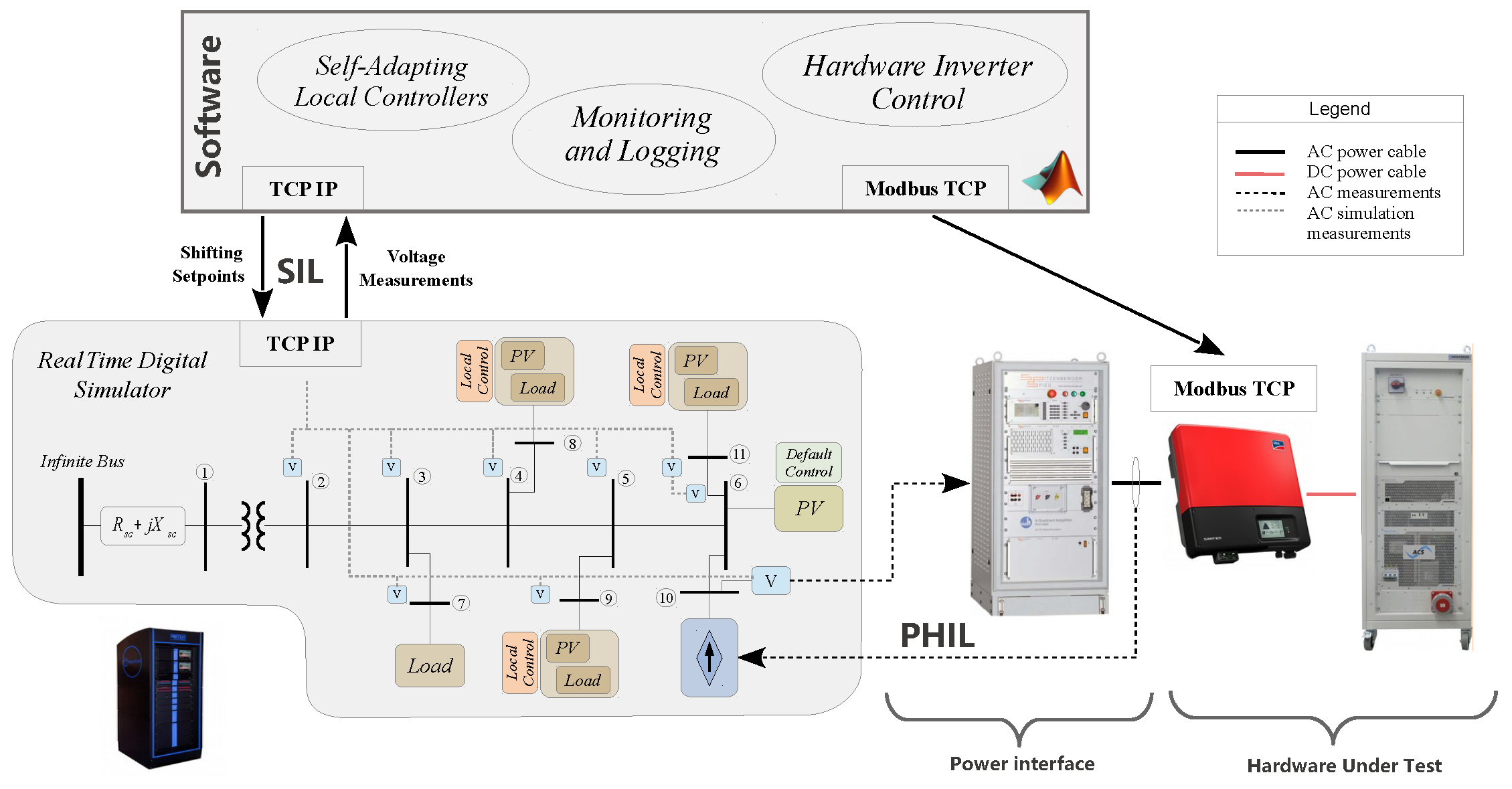
For the combined SIL-PHIL simulation, the laboratory test environment depicted in Figure 3 is used. In this setup, one of the PV inverters is replaced with a real component that represents the HuT of the PHIL test and the self-adapting algorithms represent the software under test of the SIL simulation. Thus, the self-adapting controllers are implemented in another software which interacts with the real-time simulation through reading local voltage measurements and sending the derived shifting setpoints.
The Sunny Boy 3000 TL inverter from SMA (Niestetal, Germany) [25] is used as the HuT combined with a PV simulator. This commercial inverter is capable of operating using both local control strategies, i.e., closed-loop volt/var curves or the current open-loop scheme implemented in Germany [14], and following a centralised approach receiving specific P and Q setpoints. This allows us to first calculate the shifting from the self-adapting algorithm, apply the measured voltage to the characteristic volt/var curve of the PV, and finally calculate and send specific reactive power setpoints to the inverter.
In this setup, the power interface is composed of a Spitzenbenger Spies PAS5000 linear amplifier (Viechtach, Germany) and the Tektronix A622 current probe (Beaverton, OR, USA). The DN shown in Figure 3 is simulated in the RTDS, and the voltage at the Node 10 is transferred as a reference low level signal to the power interface (via the D/A interface of the RTDS). This reference voltage is amplified and applied to the real PV inverter. The AC current flowing from the inverter is then measured and sent back to the simulation closing the loop (via the A/D interface of the RTDS).
Finally, the communication of the RTDS with the external software is implemented with a communication interface, which is based on the TCP-IP protocol. The self-adapting algorithms are again realised in MATLAB and tested in a SIL concept combined with the PHIL simulation. The nodal voltages of the simulated DN are provided to the software and the calculated results are sent back to the simulation to close the loop.

5.3. Individual Data-Driven Local Control Schemes

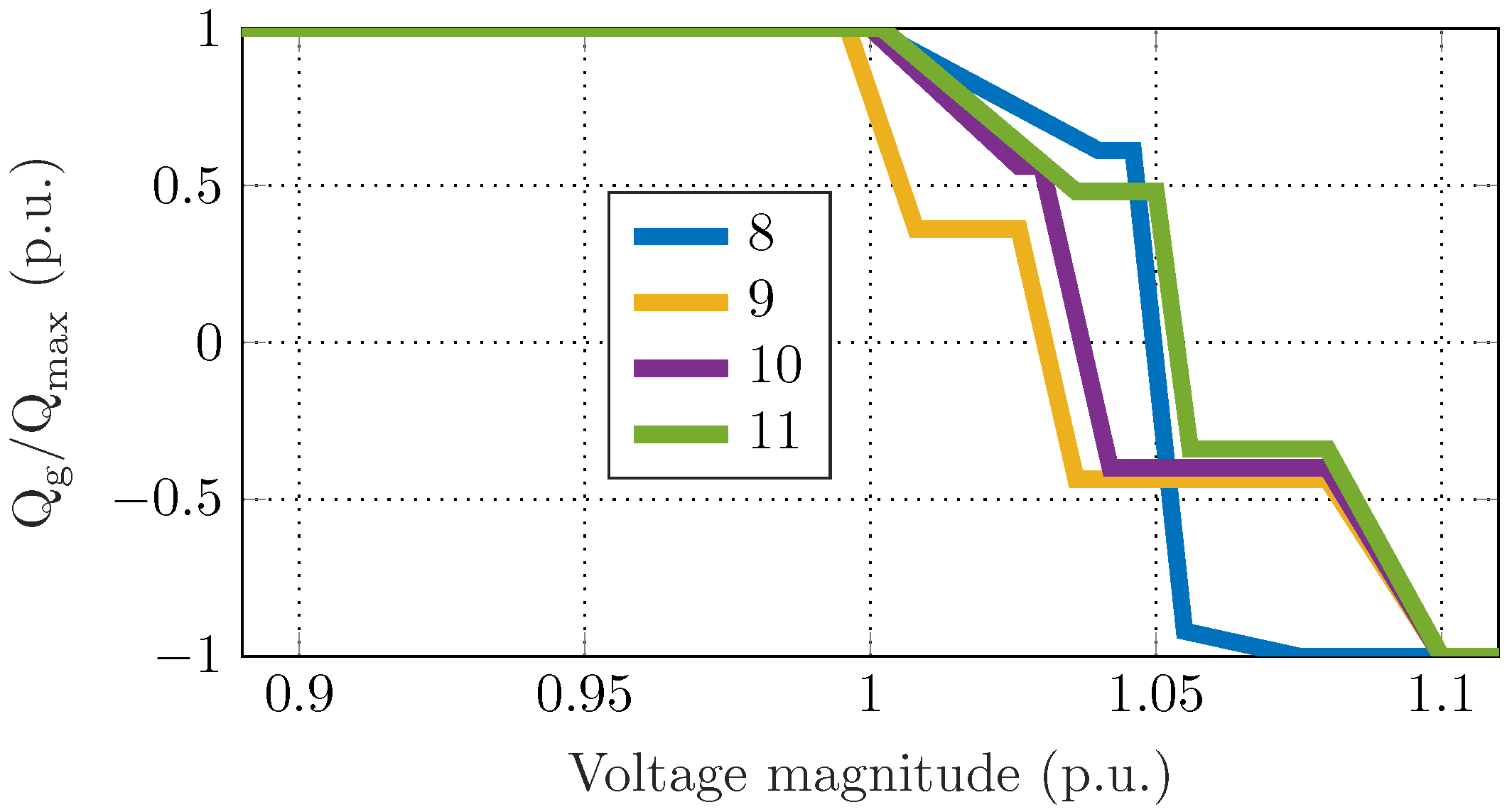
The derivation of the data-driven local controllers is based on a 30-day summer dataset following Section 2. The resulting control curves are shown in Figure 4. All the PV units show a capacitive behaviour at low voltages to increase voltages, optimise losses and to satisfy the local reactive power demands by local injections. As voltage approaches the maximum acceptable value of 1.05 p.u., the units start switching into inductive mode. The higher the voltage, the more reactive power is absorbed by the units. However, the fact that for the maximum voltage value of 1.05 p.u., not all units absorb their maximum reactive power shows that in the underlying optimization problem the capacity was enough to solve the local overvoltage issues.

5.4. Experimental Results

In this section, we first present the results under expected conditions (included in the training dataset) and we investigate the suitability of data-driven controllers to emulate the optimal response. Then, we present the behaviour under new conditions due to the installation of a PV unit which was not considered in the offline methodology. The latter reveals the risks from using AI-based controls in real-time and highlights the contributions of the proposed online adjustment algorithm to satisfy the power quality constraint.

5.4.1. Expected Conditions

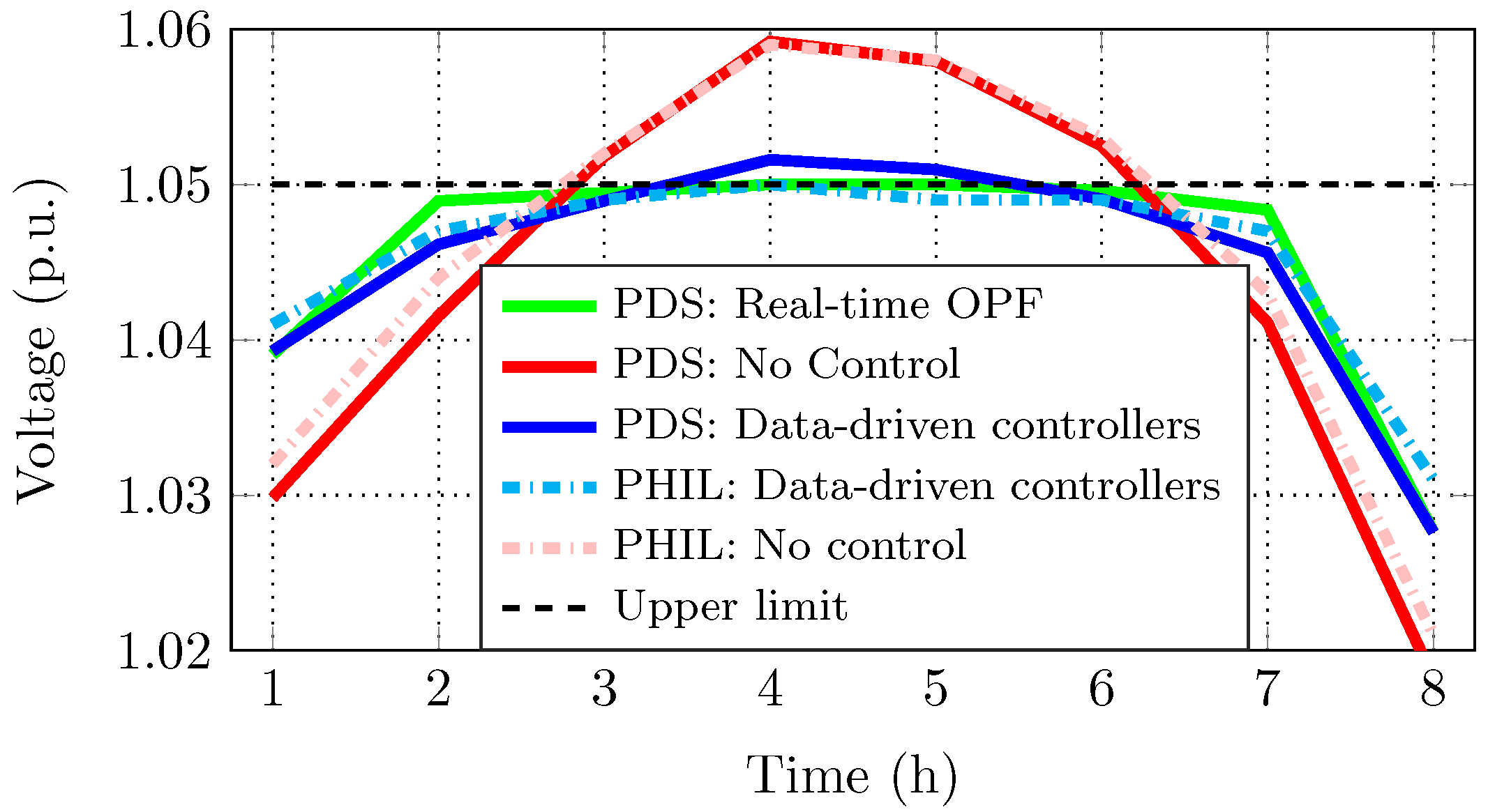
The real-time behaviour is evaluated using different input data from the training set. More specifically, we use the operating conditions of a summer day in July and provide the power flow results for the time period of 8 h. Figure 5 shows the voltage magnitude evolution of the considered methods. First, we observe that operating without control, i.e., when the PV units inject their maximum available active power, results in overvoltage issues. The real-time OPF method serves as a benchmark case that shows the optimal response that satisfies all network constraints at minimum cost. We observe that the data-driven approach emulates satisfactorily the real-time OPF due to the customised and optimised volt/var curves of Figure 4.
The experimental results using the RTDS verify the suitability of the data-driven schemes to emulate the optimal response under expected conditions. The experimental results are closer to the simulation results at high solar radiation hours for the case without reactive power control, and the largest deviation for both cases is 0.7 % .

5.4.2. Online Self-Adapting Algorithm

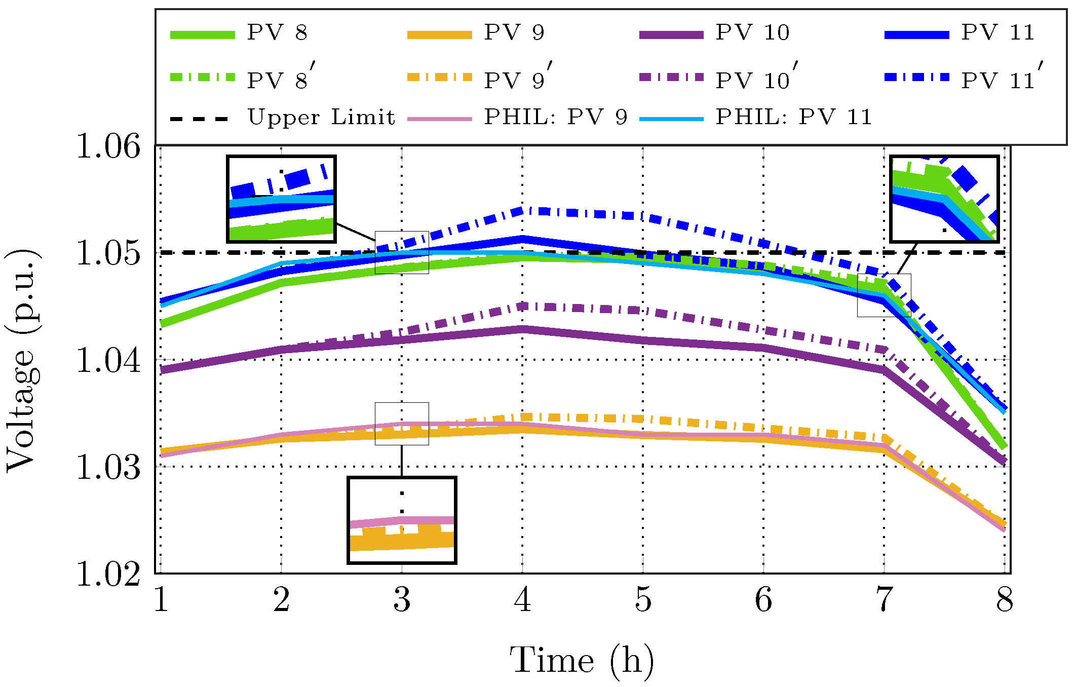
In this part, we assume that a new PV unit is installed at node 6 with the same installed capacity as the PV unit at node 10. This unit is operating according to the standard volt/var curve as indicated in the grid codes [14] and the location is chosen such that its impact on the neighboring nodes is significant (installations closer to the secondary of the transformer where voltage is regulated would have less impact on the system). Figure 6 shows the voltage evolution with (solid lines) and without (dash-dotted lines) the online modification of the volt/var curves. The shifting step is set to 0.1 p.u. and it was adequate to reduce the overvoltage issues of node 11. The combined SIL-PHIL experiment which considers the self-adapting algorithm confirmed the simulation results as can be seen by the voltage measurements at nodes 9 and 11.

5.4.3. Comparative Evaluation of Optimal, Adaptive and Non-Adaptive Schemes

Finally, in this part, we compare the whole system response in terms of power quality constraint satisfaction, loss minimization and the use of flexibility in terms of reactive power control. Through the different setups, we highlight the inefficiencies of current industrial practices, the emulation of the optimal response via the data-driven controllers, the sub-optimality for not updating the optimised curves by rerunning the offline methodology, and the suitability of the online algorithm to solve local voltage issues. More specifically, we consider the following cases:
  • Method 0: PVs inject the maximum active power at unity power factor. This scheme shows the real-time behaviour when no control measures are taken.
  • Method 1: PVs operate according to the same standardised volt/var curves from the IEEE grid-codes [26]. The maximum acceptable voltage is set to 1.05 p.u. We use this scheme as the benchmark for the current industrial practice without the possibility for online adjustments.
  • Method 2: PVs operate according to the German grid-code [14]. DGs become inductive when injecting more than 50% of their installed capacity. The power factor decreases linearly from 1 to 0.95 or 0.9 based on the DG capacity. This scheme is also used as the current open-loop industrial practice without online adjustments.
  • Method 3: PVs are controlled with a centralised OPF algorithm summarised in Section 2. This scheme is used as the benchmark for the best achievable performance.
  • Method 4: The offline training methodology is repeated considering the addition of the PV unit. The PV inverters implement the updated volt/var curves which refer to the new conditions, and the self-adapting algorithm in case of unexpected overvoltage issues.
  • Method 5: The PV units are operating according to the initial local data-driven schemes without re-training, i.e., the PV unit at node 6 is not considered in the design stage. Potential overvoltages are tackled by the online algorithm proposed in Section 3.
Table 1 summarises the comparison in terms of the maximum observed voltage magnitude, the total system losses and the use of reactive power m Q , calculated by,
m Q = t = 1 N hor j = 1 N b Q j , t g t = 1 N hor j = 1 N b Q j , t g , max .
Both the current industrial practices, i.e., methods 1 and 2 result in overvoltages and increase the losses compared to the “no control” method 0. Method 2 utilises more reactive power in terms of additional demand, showing the highest losses since more reactive power is needed during times with high solar radiation. The data-driven methods 4 and 5 manage to mimic the optimal centralised response of method 3 closely. Method 4 shows a marginally closer to the optimal behaviour due to the repetition of the offline methodology and the derivation of the updated optimised volt/var curves which consider the added PV unit. The difference between methods 4 and 5 depends on the potential to modify the characteristic curves online and on the location and the size of the added element, i.e., a larger PV unit would provoke larger deviations. Characteristic curves saturated at 1 p.u. do not provide additional flexibility to solve local power quality issues online, when the real-time conditions have changed significantly from the training dataset.

6. Conclusions

Active distribution grids rely on real-time DG control to ensure a safe and reliable grid operation. Data-driven, purely local, strategies can bridge the gap between optimal (but costly) centralised approaches and robust (but suboptimal) existing local schemes. In this paper, we verified experimentally the behaviour of data-driven controllers and proposed an online self-adapting algorithm to modify the control schemes when local power quality issues are observed. The experimental verification of the results can be used towards the development of new grid codes that will allow the implementation of state-of-the-art methods developed in this paper, such that the operational flexibility provided by active DGs is used to alleviate power quality problems, defer grid investments and optimise the grid use. Future work will focus on experimental studies on ancillary service provision including battery energy storage systems and demand response schemes.

Author Contributions

Conceptualization, S.K., P.A., A.V. and P.K.; methodology, S.K., P.A., A.V. and P.K.; software, S.K., P.A., A.V. and P.K.; writing—original draft preparation, S.K., P.A., A.V. and P.K.; writing—review and editing, G.H. and N.H.; supervision, G.H. and N.H.; project administration, G.H. and N.H.; funding acquisition, G.H. and N.H. All authors have read and agreed to the published version of the manuscript.

Funding

This research received no external funding.

Conflicts of Interest

The authors declare no conflict of interest.

Nomenclature

(A) Indices & functions
jIndex of nodes.
iIndex of branches.
lIndex of lines.
tIndex of time.
i ¯ Index for the current iteration of the segmented regression problem.
( · ) * Superscript indicating the complex conjugate.
(B) Parameters
I ( · ) The indicator function which becomes one when the statement inside is true.
N b Total number of network nodes (−).
N b r Total number of network branches (−).
c o s ( ϕ l ) Power factor of the load (−).
Δ t Length of a time interval within the optimization horizon (h).
P g , j , t max Maximum available active power of the DER connected at node j, at time t (kW).
C P Fixed cost of curtailing active power ( CHF kWh ).
C Q Fixed cost of providing reactive power support (DER opportunity cost or contractual agreement) ( CHF kVArh ).
V ¯ j , t * Voltage magnitude at node j, and time t; the bar indicates that the known value from the previous Backward/Forward Sweep iteration is used (p.u.).
V slack Complex voltage at the slack bus (here assumed to be 1 / 0 ° ¯ (p.u.).
V min / V max Minimum/Maximum acceptable voltage magnitude (here assumed to be 0.95 / 1.05 (p.u.).
I i max Maximum thermal limit for the i-th branch (p.u.).
P g , j , t min / P g , j , t max Upper and lower limits for the active DER power at node j, and time t (kW).
n s Number of breakpoints for the segmented regression problem (−).
s k i ¯ Known breakpoints used for the fitting of the segmented regression problem at the current iteration i ¯ (−).
N Number of the voltage series in terms of the reactive characteristic curves (−).
(C) Variables
P j , t g Active power injection of the DER connected at node j, at time t (kW).
P j , t c Curtailed active power of the DER connected at node j, at time t (kW).
P i , t loss Active power losses at branch i, at time t (kW).
P j , t l / Q j , t l Active and reactive demand of constant power type at node j, at time t (kW).
Q j , t g Reactive power injection (positive) or absorption (negative) of the DER connected at node j, phase z, at time t (kVAr).
I i , t br Current flowing at the i-th branch, at time t (p.u.)
x ˜ i ¯ Model for the reactive power control based on the segmented regression problem with unknown breakpoints (−).
β 0 / β k Left slope and difference-in-slopes values of the fitting problem (−).
x ˜ 0 The model intercept (p.u.).
γ Parameter which updates the location of the breakpoints towards the optimal one in the regression problem (−).
(D) Vectors and Matrices
uVector of the available active control measures.
I inj Vector of bus injections for all nodes.
I t br Vector of branch flow currents for all branches.
I max Vector of the maximum branch current for all branches.
B I B C Matrix with ones and zeros, capturing the radial topology of the network.
B C B V Matrix with the complex impedances of the lines as elements.
Φ ( j ) Feature matrix containing the optimal setpoints which refer to the local measurements (features) that are used for the design of the local controllers.
X j Vector containing the N J voltage series in terms of the active or reactive characteristic curves.
(E) Acronyms
BFSBackward Forward Sweep
BIBCBus Injection to Branch Current
BCBVBranch Current to Bus Voltage
CHILController-Hardware-in-the-loop
DERDistributed Energy Resource
DRTSDigital Real-Time Simulator
DGDistributed Generator
DNDistribution Network
HILHardware-in-the-loop
HuTHardware-under-Test
LVLow Voltage
OPFOptimal Power Flow
PVPhotovoltaic
PDSPurely Digital Simulations
PHILPower-Hardware-in-the-loop
RTDSReal Time Digital Simulator
RSSResidual Sum-of-Squares
RSSVRoot-Sum-of-Squares Value
SILSoftware-in-the-Loop

References

  1. Karagiannopoulos, S.; Aristidou, P.; Hug, G. Data-driven Local Control Design for Active Distribution Grids using off-line Optimal Power Flow and Machine Learning Techniques. IEEE Trans. Smart Grid 2019, 10, 6461–6471. [Google Scholar] [CrossRef] [Green Version]
  2. Dobbe, R.; Sondermeijer, O.; Fridovich-Keil, D.; Arnold, D.; Callaway, D.; Tomlin, C. Towards Distributed Energy Services: Decentralizing Optimal Power Flow with Machine Learning. arXiv 2018, arXiv:1806.06790. [Google Scholar] [CrossRef]
  3. Karagiannopoulos, S.; Dobbe, R.; Aristidou, P.; Callaway, D.; Hug, G. Data-driven Control Design Schemes in Active Distribution Grids: Capabilities and Challenges. In Proceedings of the 2019 IEEE Milan PowerTech, Milan, Italy, 23–27 June 2019. [Google Scholar]
  4. Garg, A.; Jalali, M.; Kekatos, V.; Gatsis, N. Kernel-Based Learning for Smart Inverter Control. arXiv 2018, arXiv:1807.03769. [Google Scholar]
  5. Eggli, A.; Karagiannopoulos, S.; Bolognani, S.; Hug, G. Stability Analysis and Design of Local Control Schemes in Active Distribution Grids. IEEE Trans. Power Syst. 2019, 36, 1900–1909. [Google Scholar]
  6. Kotsampopoulos, P.; Hatziargyriou, N.; Bletterie, B.; Lauss, G.; Strasser, T. Introduction of advanced testing procedures including PHIL for DG providing ancillary services. In Proceedings of the 39th Annual Conference of the IEEE Industrial Electronics Society, Vienna, Austria, 10–13 November 2013; pp. 5398–5404. [Google Scholar]
  7. Maniatopoulos, M.; Lagos, D.; Kotsampopoulos, P.; Hatziargyriou, N. Combined control and power hardware in-the-loop simulation for testing smart grid control algorithms. IET Gener. Transm. Distrib. 2017, 11, 3009–3018. [Google Scholar] [CrossRef]
  8. Kotsampopoulos, P.C.; Lehfuss, F.; Lauss, G.F.; Bletterie, B.; Hatziargyriou, N.D. The limitations of digital simulation and the advantages of PHIL testing in studying distributed generation provision of ancillary services. IEEE Trans. Ind. Electron. 2015, 62, 5502–5515. [Google Scholar] [CrossRef]
  9. Kotsampopoulos, P.C.; Kleftakis, V.A.; Hatziargyriou, N.D. Laboratory education of modern power systems using PHIL simulation. IEEE Trans. Power Syst. 2016, 32, 3992–4001. [Google Scholar] [CrossRef]
  10. Bolognani, S. Grid Topology Identification via Distributed Statistical Hypothesis Testing. In Big Data Application in Power Systems; Elsevier: Amsterdam, The Netherlands, 2018; pp. 281–301. [Google Scholar]
  11. Olivier, F.; Sutera, A.; Geurts, P.; Fonteneau, R.; Ernst, D. Phase identification of smart meters by clustering voltage measurements. In Proceedings of the 2018 Power Systems Computation Conference (PSCC), Dublin, Ireland, 11–15 June 2018; pp. 1–8. [Google Scholar]
  12. Fortenbacher, P.; Zellner, M.; Andersson, G. Optimal sizing and placement of distributed storage in low voltage networks. In Proceedings of the 19th Power Systems Computation Conference, Genova, Italy, 20–24 June 2016. [Google Scholar] [CrossRef] [Green Version]
  13. Karagiannopoulos, S.; Aristidou, P.; Roald, L.; Hug, G. Operational Planning of Active Distribution Grids under Uncertainty. In Proceedings of the X Bulk Power Systems Dynamics and Control Symposium, Espinho, Portugal, 27 August–1 September 2017. [Google Scholar]
  14. VDE-AR-N 4105. Generators Connected to the LV Distribution Network-Technical Requirements for the Connection to and Parallel Operation with Low-Voltage Distribution Networks; Technical Report for VDE FNN: Berlin, Germany, 2011. [Google Scholar]
  15. Muggeo, V.M.R. Estimating regression models with unknown break-points. Stat. Med. 2003, 22, 3055–3071. [Google Scholar] [CrossRef] [PubMed]
  16. Dobbe, R.; Hidalgo-Gonzalez, P.; Karagiannopoulos, S.; Henriquez-Auba, R.; Hug, G.; Callaway, D.; Tomlin, C. Learning to control in power systems: Design and analysis guidelines for concrete safety problems. Electr. Power Syst. Res. 2020, 189, 106615. [Google Scholar] [CrossRef]
  17. Werner, S.; Masing, L.; Lesniak, F.; Becker, J. Software-in-the-loop simulation of embedded control applications based on virtual platforms. In Proceedings of the 25th International Conference on Field Programmable Logic and Applications (FPL), London, UK, 2–4 September 2015. [Google Scholar]
  18. Muresan, M.; Pitica, D. Software in the loop environment reliability for testing embedded code. In Proceedings of the IEEE 18th International Symposium for Design and Technology in Electronic Packaging, Alba Iulia, Romania, 25–28 October 2012. [Google Scholar]
  19. Faruque, M.O.; Strasser, T.; Lauss, G.; Jalili-Marandi, V.; Forsyth, P.; Dufour, C.; Dinavahi, V.; Monti, A.; Kotsampopoulos, P.; Martinez, J.A.; et al. Real-time simulation technologies for power systems design, testing, and analysis. IEEE Power Energy Technol. Syst. J. 2015, 2, 63–73. [Google Scholar] [CrossRef]
  20. Ren, W.; Steurer, M.; Baldwin, T.L. Improve the stability and the accuracy of power hardware-in-the-loop simulation by selecting appropriate interface algorithms. IEEE Trans. Ind. Appl. 2008, 44, 1286–1294. [Google Scholar] [CrossRef]
  21. Löfberg, J. YALMIP: A Toolbox for Modeling and Optimization in MATLAB. In Proceedings of the 2004 IEEE International Conference on Robotics and Automation, Taipei, Taiwan, 2–4 September 2004. [Google Scholar]
  22. Gurobi Optimization, Inc. Gurobi Optimizer Reference Manual; Gurobi Optimization, Inc.: Beaverton, OR, USA, 2016. [Google Scholar]
  23. RTDS Technology Inc. Real-Time Simulation. Winnipeg, MB, Canada. Available online: http://www.rtds.com (accessed on 5 October 2019).
  24. Strunz, K.; Abbasi, E.; Abbey, C.; Andrieu, C.; Gao, F.; Gaunt, T.; Gole, A.; Hatziargyriou, N.; Iravani, R. Benchmark Systems for Network Integration of Renewable and Distributed Energy Resources; CIGRE, Task Force C6.04: Paris, France, 2014; pp. 4–6. [Google Scholar]
  25. SMA Solar Technology AG. Sunny Boy 3000TL/3600TL/4000TL/5000TL with Reactive Power Control; SMA: Niestetal, Germany, 2015; Available online: http://files.sma.de/dl/15330/SB30-50TL-21-BE-en-11.pdf (accessed on 5 October 2019).
  26. IEEE 1547-2018. Standard for Interconnection and Interoperability of Distributed Energy Resources with Associated Electric Power Systems Interfaces; Standard; IEEE: Piscataway, NJ, USA, 2018. [Google Scholar]
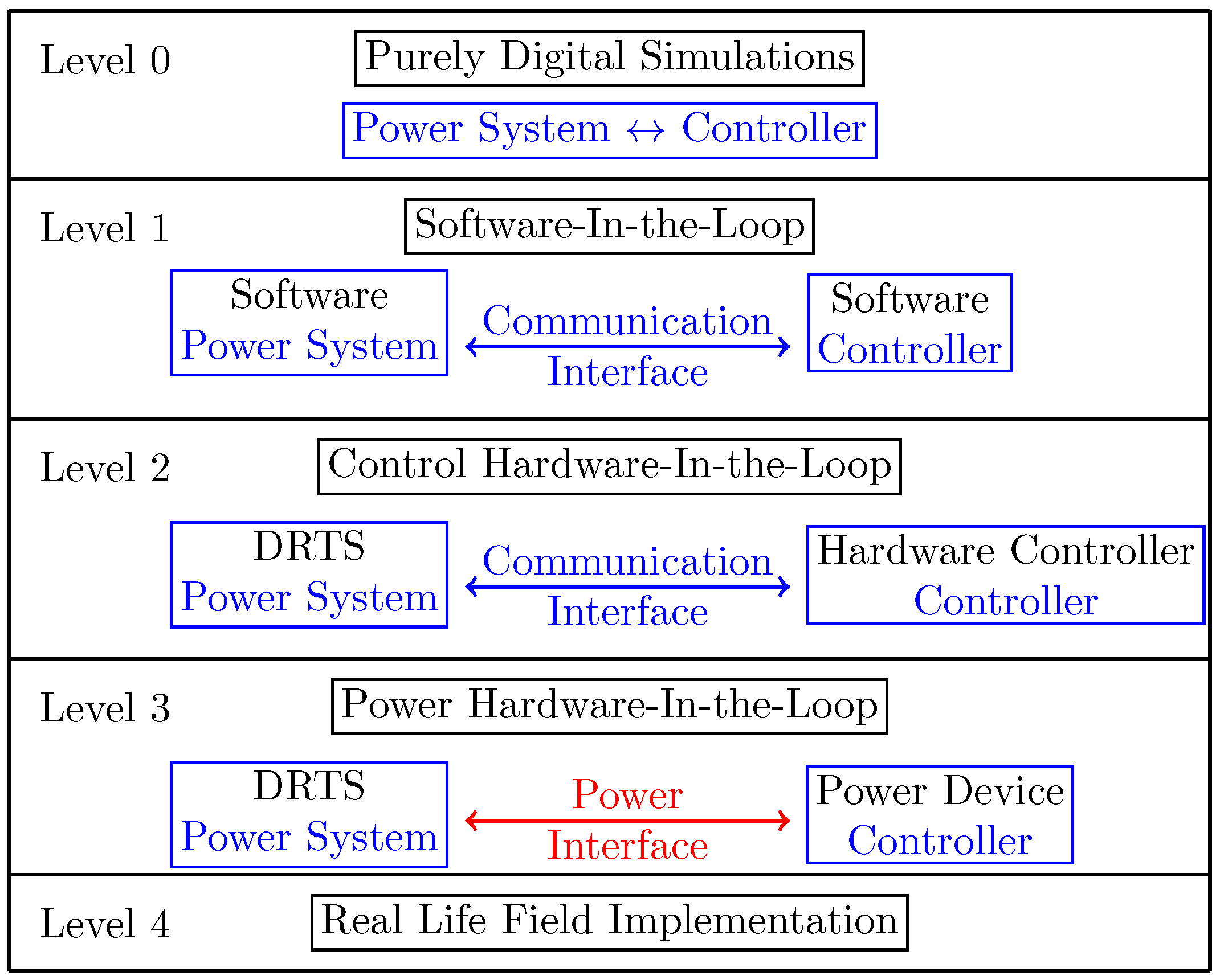
Figure 1. Testing levels for controllers and power components, adapted from [7].
Energies 14 02837 g001
Figure 2. Simplified Cigre LV grid for HIL simulations.
Energies 14 02837 g002
Figure 3. Overview of the combined SIL-PHIL experimental setup.
Energies 14 02837 g003
Figure 4. Data-driven volt/var curves for each PV unit.
Energies 14 02837 g004
Figure 5. Voltage evolution of node 11.
Energies 14 02837 g005
Figure 6. Voltage evolution at PV nodes with (indicated by solid lines) and without (indicated with the dash-dotted lines) using the self-adapting algorithm.
Energies 14 02837 g006
Table 1. Summarised monthly results based on PDS.
Method012345
Losses (%)5.745.786.475.115.185.17
| V | max (p.u.)1.0711.0541.0531.051.0511.052
m Q ( % ) → (17)09.1830.5567.2962.3859.39
Publisher’s Note: MDPI stays neutral with regard to jurisdictional claims in published maps and institutional affiliations.