Article

Dual Resonant Frequency Inductive Power Transfer in an Underwater Tight Coupling System

1
College of Electrical Engineering, University of Zhejiang, Hangzhou 310027, China
2
School of Automation, University of Hangzhou Dianzi, Hangzhou 310000, China
*
Author to whom correspondence should be addressed.
Energies 2021, 14(1), 242; https://doi.org/10.3390/en14010242
Submission received: 27 November 2020 / Revised: 25 December 2020 / Accepted: 29 December 2020 / Published: 5 January 2021

Abstract

:
The application of wireless power transfer technology in the underwater environment proposes both opportunities and challenges to undersea power feeding. Due to the attenuation of electromagnetic waves in seawater, the distance between transmitter and receiver is always maintained at a minimum value, which results in tight coupling between the transmitter and receiver. The tight coupling condition provides a low impedance loop for high-order harmonic, so the component of the harmonic wave is thus significantly increased and cannot be ignored in the power transmission system. In order to fully utilize the harmonic energy, a fundamental-harmonic dual-channel system was proposed and studied in this paper. Compared with single-channel systems transmitting fundamental wave only, the dual-channel system has higher power transmission capability, while the loss in dual channel system can be less than that of a single-channel system after proper optimization. A 3 kW experiment platform is established to verify the effectiveness of theoretical analysis.

1. Introduction

The development of underwater robotics is an important field of research and a promising industrial application since it represents a sustainable solution to exploit ocean resources with a reasonable environmental impact [1]. The application of wireless power transfer technology to underwater devices [2,3,4] has potential technical and economic benefits, compared to the wet plug technology, which is complicated to implement and expensive to maintain(shown in Figure 1). Wireless power transfer facilitates electrical isolation between the transmitter and receiver and eliminates the compulsory physical contact from power feeder to consumer [5,6,7]. However, currently, the majority of research mainly focuses on wireless power transfer in the atmospheric environments [8,9], the application in the undersea environment raised new challenges to the development of the WPT(wireless power transfer) technology. On one hand, the conductivity of air at standard temperature and pressure is nearly zero, so the medium loss is not incorporated in the analysis of the theoretical model. The eddy current loss in seawater cannot be ignored, and it has a significant influence on the system efficiency at high operation frequency. On the other hand, wireless power transfer requires a stable alignment of the transmitter and receiver; however, the electromagnetic coupler in seawater is vulnerable to ocean current disturbance, additional mechanical fixing design is required.
Due to the attenuation of electromagnetic wave in seawater [10,11,12], the distance between transmitter and receiver is maintained at a minimum value, which results in tight coupling between the transmitter and receiver(the coupling coefficient is greater than 0.5), so the underwater inductive power transfer system is a strong coupling system [13,14,15,16,17]. The component of the harmonic wave is thus significantly increased [18,19,20] and cannot be ignored in the power transmission system. This paper proposes a dual resonant frequency inductive power transfer system, in which the fundamental and third harmonic waves are transferred simultaneously. The multi-frequency WPT for smart power distribution among multi-standard receivers has been investigated in [21]. A GaN (Gallium nitride)-based programmable pulse width modulation [22] and a concurrent transmitter consisting of two independent transmitters [23] were proposed and implemented to support the dual-mode WPT operation. A scheme that amplifies both the fundamental and third harmonic generated by a full-bridge inverter was proposed to implement the double-frequency WPT (DF-WPT) [24]. A multi-frequency superposition methodology [25] and a multi-frequency drive configuration [26] have been proposed to achieve high efficiency and flexible power distribution for multi-load WPT. In order to reduce the effect of electromagnetic interference, snubbers for power switch devices are necessary, and their effectiveness has been verified in previous literature [27].
In this paper, the compensation network on the primary side is designed with LC stepped structure featuring multiple resonant frequencies. The dual-channel wireless power transfer system is compared with the single-channel system in power losses, including winding loss and circuit loss. Theoretical analysis is validated through simulation and experimental results.

2. Dual Resonant Frequency Inductive Power Transfer

This section starts with the analysis in a mutual inductance model transmitting only a fundamental wave, and an additional circuit branch is added to build the fundamental-harmonic dual-path topology. As extra rectifier bridge and coils were used, the dual channel system transmitting both fundamental and harmonic wave was analyzed and compared with single-channel WPT system in system losses.

2.1. Dual Channel Inductive Power Transfer

The single-channel S-S (series to series) compensated wireless power transfer system is shown in Figure 2.
Through the Fourier decomposition of the Inverter output square wave voltage,
v A B = 4 U s π m = 1 , 3 , 5 . . . 1 m sin ( m ω t )
w is the switching angle frequency.
Subscript m is defined as the circuit parameter in m-th harmonic.
The impedances on the primary and secondary sides are:
Z p _ m = j ( m ω ) L p + 1 j ( m ω ) C p
Z s _ m = j ( m ω ) L s + 1 j ( m ω ) C s + R L
The reflected impedance of ZR_m on the primary side is:
Z R _ m = [ ( m ω ) M ] 2 Z s _ m
The total input impedance on the primary side is:
Z i n _ m = Z P _ m + Z R _ m
At resonant frequency fr, the fundamental input impedance is:
Z i n _ r = ω r 2 M 2 R L
The quality factor of secondary coil Qs is defined as:
Q s = ω r L s R L
The normalized input impedance ZinN_m is:
Z i n N _ m = j m 2 1 m Q s 1 k 2 + m 3 m + j Q s ( m 2 1 )
The normalized input harmonic current is:
I P N _ m = I s _ m I s _ r = U s _ m / | Z i n _ m | U s _ r / | Z i n _ r | = 1 m | Z i n _ m N | = 1 m | j m 2 1 m Q s 1 k 2 + m 3 m + j Q s ( m 2 1 ) |
Is_m is the total input current on the primary side, and Is_r is the fundamental input current at resonant frequency fr.
Under different quality factors, the variation of the third harmonic component with the coupling coefficient is shown in Figure 3. With the increase of the coupling coefficient, the third harmonic component increases first before decreasing. When the transmitter and receiver coils are under tight coupling condition, the component of third harmonic cannot be neglected.
In an underwater WPT system, the gap between the transmitter and receiver coil is tiny, which results in a high coupling coefficient, and the harmonic component is significantly increased.
In order to transfer the fundamental and harmonic wave simultaneously, an additional circuit is usually added to transfer the harmonic wave. A schematic diagram of the fundamental-harmonic dual-path topology is shown in Figure 4. The fundamental and harmonic compensation network is designed at its respective resonant frequency. The two networks share the same inverter bridge. However, this strategy requires two compensation networks and two couplers, which significantly increase the cost and volume of the system; meanwhile, the two outputs will affect the original input angle, and the inverter no longer works under the ZVS (zero voltage switching) condition.
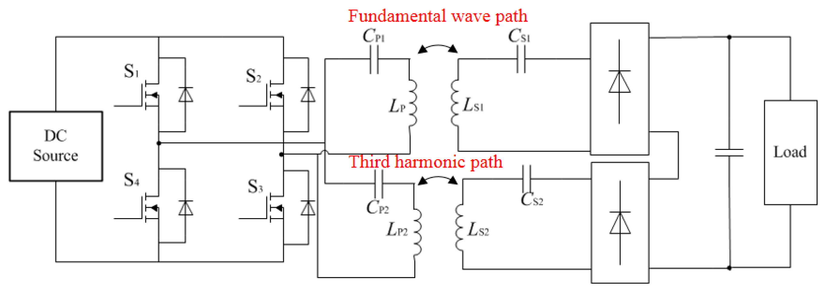
As a result, in order to transfer the fundamental and harmonic wave simultaneously, the primary compensation network needs to have multiple resonant frequencies, as shown in Figure 5. Resistor–capacitor–diode clamp snubber was added to the inverter to reduce electromagnetic interference. Multiple resonant frequency network usually employs the LC stepped structure, and the combination of multiple resonant networks enables the system to have multiple resonant frequencies, due to the frequency-selective characteristic of a single LC network. Xe is a reactance unit used to control the phase. The secondary side employs multiple output circuits, to transfer the fundamental and third harmonic wave independently. As the proposed system topology features constant voltage output, the rectifier bridge outputs can be connected in series.
The additional passive compensation network is added on the receiver side (Lr1 and Cr1, Lr2 and Cr2) to eliminate the effects of cross-coupling. As Channel 1(Ls1 and Cs1) is designed to transfer the fundamental wave and Channel 2(Ls2 and Cs2) is designed to transfer only the third harmonic, Lr1 and Cr1 are designed to be resonant at the third harmonic frequency, and Lr2 and Cr2 are designed to be resonant at the fundamental frequency. For Channel 1, the impedance of the third harmonic is infinite, so the third harmonic can hardly go through Channel 1. Similarly, a fundamental wave can hardly go through Channel 2.

2.1.1. Determination of Circuit Parameters

As to the LCL compensation network (shown in Figure 6a, LA resonant with CA ensures constant current output, and when LA equals LB, the input impedance is resistive). The LCL compensation network is a third-order system with a single resonant frequency. A dual resonant frequency system can be obtained by adding CB after LB, as shown in Figure 6b.
Define sω as negative frequency, s ω _ m = j ω _ m
The current gain of dual resonant frequency network GiP is:
G i P = I P U A B = 1 s ω 4 L A L B C A + s ω ( L A + L B ) + [ s ω 4 L A L B C A C B + s ω 2 ( L A C A + L A C B + L B C B ) + 1 ] Z o
when s ω 4 L A L B C A C B + s ω 2 ( L A C A + L A C B + L B C B ) + 1 = 0 , GiP is independent of load Zo. When the system resonant at the fundamental and third harmonic frequency, GiP is independent of load Zo.
L A C A + L A C B + L B C B L A L B C A C B = 10 ω _ 1 2
1 L A L B C A C B = 1 9 ω _ 3 4
The current gain is:
G i P ( ω _ 1 ) = G i P ( ω _ 3 ) = 1 s ω 3 L A L B C A + s ω ( L A + L B )
The current gains for fundamental and third harmonic are defined as G_1 and G_3, respectively:
G _ 1 = 1 L A L B C A ω _ 1 3 ( L A + L B ) ω _ 1
G _ 3 = 1 L A L B C A ω _ 3 3 ( L A + L B ) ω _ 3
Solving the equations,
{ L A = 1 3 ω _ 1 ( G _ 3 3 G _ 1 ) L B = ( G _ 1 3 G _ 3 ) 2 8 ω _ 1 G _ 1 G _ 3 ( 3 G _ 1 G _ 3 )
{ C A = ( 3 G _ 1 G _ 3 ) 2 8 ω _ 1 ( 3 G _ 3 G _ 1 ) C B = 8 G _ 1 G _ 3 3 ω _ 1 ( G _ 1 3 G _ 3 )
Therefore, given the current gains G_1 and G_3 and fundamental frequency, the values of LA, LB, CA, and CB can be determined.

2.1.2. System Output Characteristics

The constant voltage output condition is:
{ ω 1 L s 1 1 ω 1 C s 1 + ω 1 L r 1 1 ω 1 2 L r 1 C r 1 = 0 ω 3 L s 2 1 ω 3 C s 2 + ω 3 L r 2 1 ω 3 2 L r 2 C r 2 = 0
The two receiver circuits are decoupled under the condition:
{ 1 ω 3 2 L r 1 C r 1 = 0 1 ω 1 2 L r 2 C r 2 = 0
The AC voltage gain is:
{ G v 1 = | U o 1 U i 1 | = | ω 1 M P S 1 I P 1 U i 1 | = ω 1 M P S 1 | G i P 1 | G v 2 = | U o 2 U i 3 | = | ω 3 M P S 2 I P 3 U i 3 | = ω 3 M P S 2 | G i P 3 |
As the rectifier bridge outputs connect in parallel,
U o = π 4 ( U o 1 + U o 2 )
The power in each receiver circuit is distributed according to the ratio of voltage distribution,
{ P o 1 = U o 1 U o · U o 2 R L = U o 1 U o R L P o 2 = U o 2 U o · U o 2 R L = U o 2 U o R L
If the rectifier bridge loss is neglected, the power flows in the rectifier equals the power flows out,
{ U o 1 I s 1 = P o 1 = U o 1 U o R L = I o I o 1 R L U o 2 I s 2 = P o 2 = U o 2 U o R L = I o I o 2 R L
Therefore, the equivalent resistances with the rectification of two receiver circuits are:
{ R E 1 = U o 1 I s 1 = 16 π 2 R L | M P S 1 G i P 1 | | M P S 1 G i P 1 | + | M P S 2 G i P 3 | R E 2 = U o 2 I s 2 = 16 π 2 R L | M P S 2 G i P 3 | | M P S 1 G i P 1 | + | M P S 2 G i P 3 |

2.2. Comparison of Dual and Single Channel Systems

The comparison of dual- and single-channel systems is carried out in terms of inverter circuit conduction loss and winding loss in a loosely coupled transformer.
The total power output of the system is Po, the power output of receiver circuit 1 is Po1, and the power output of receiver circuit 1 is Po2.
To define power factor λ, the equivalent load resistance of the single-channel system is:
{ λ = P o 1 P o = | M P S 1 G i P 1 | | M P S 1 G i P 1 | + | M P S 2 G i P 3 | 1 λ = P o 2 P o = | M P S 2 G i P 3 | | M P S 1 G i P 1 | + | M P S 2 G i P 3 |
Assuming the current gain of the single-channel system is GiP, the total power output in the single-channel system is:
R E = 8 R L π 2
P o = | ω 1 M P S 1 U i 1 G i P | 2 R E
while the power outputs in the dual-channel system are:
{ P o 1 = | ω 1 M P S 1 U i 1 G i P 1 | 2 R E 1 P o 2 = | ω 3 M P S 2 U i 3 G i P 3 | 2 R E 2
Defining δ = MPS1/MPS2, solving (17)–(20), and normalizing current gain GiP1, GiP3 and equivalent resistance RE1 and RE2:
{ G i P 1 _ N = G i P 1 G i P = 2 λ , G i P 3 _ N = G i P 3 G i P = 2 δ ( 1 λ ) R E 1 _ N = R E 1 R E = 2 λ , R E 2 _ N = R E 2 R E = 2 ( 1 λ )

2.2.1. Rectifier Circuit Conduction Loss

Assume there is no loss in passive elements, the output power from the inverter equals the input power to the rectifier, and the input current on the primary side is as follows:
Single channel:
I i n = | ω 1 M P S 1 G i p | 2 R E U i n
Dual channel:
{ I i n 1 = | ω 1 M P S 1 G i P 1 | 2 R E 1 · U i n 1 I i n 3 = | ω 3 M P S 2 G i P 3 | 2 R E 2 · U i n 3
The normalized input current expression is:
I i n _ N = I i n 1 2 + I i n 3 2 I i n = λ 2 + 9 ( 1 λ ) 2
The normalized input current curve of the dual-channel system is plotted in Figure 7. When the power factor λ is greater than 0.8, the input current in the dual-channel system is smaller than the single-channel system, and when λ = 0.9, the normalized current achieves its minimum value of 0.9. As the input current into the resonant network is the break-over current in the inverter circuit. As a result, to maintain a low conduction loss, the dual-channel system should be designed to work in the shaded region shown in Figure 7.

2.2.2. Winding Loss on Loosely Coupled Transformer

The fundamental and third harmonic current on the primary side is:
{ i P 1 = U i n 1 | G i P 1 | sin ( ω 1 t + ϕ 1 ) i P 3 = U i n 3 | G i P 3 | sin ( 3 ω 3 t + ϕ 3 )
in which, φ1 is the phase difference between ip1 and uin1, and φ3 is the phase difference between ip3 and uin3. As ip1 lags behind uin1 by 90°, ip3 leads uin3 by 90°, so ip1 and ip3 are in-phase. The primary current can be written as:
i p = i p 1 + i p 3 = U i n 1 | G i P 1 | sin ( ω 1 t ) + U i n 3 | G i P 3 | sin ( 3 ω 3 t )
Through the derivation with w1t, when
ω 1 t = arcsin ( ( | G i P 1 | + | G i P 3 | ) / 4 | G i P 3 | )
iP achieves its maximum value,
I p _ max = U i n 1 ( | G i P 1 | + | G i P 3 | ) 3 · 1 + | G i P 1 G i P 3 |
Through the derivation with |GiP3|, when |GiP3| = |GiP1|/2, iP_max achieves its minimum value,
min ( i p _ max ) = 3 2 U i n 1 | G i p 1 |
Therefore, the primary current amplitude of the dual-channel system can be reduced to 3 / 2 of the single-channel system, which facilitates the reduction of maximum flux density, so as to reduce EMI.
Define,
Q = ω 1 M P S 1 R E ,   Q 1 = ω 1 M P S 1 R E 1 ,   Q 2 = ω 3 M P S 2 R E 2
The currents in the secondary coil single system and dual-channel system are as follows:
Single-channel:
I s = Q | G i P | U i n 1
Dual-channel:
{ I s 1 = Q 1 | G i P 1 | U i n 1 I s 2 = Q 2 | G i P 3 | U i n 3
As shown in Figure 8, Rp, Rs1, Rs2 are the equivalent resistance of each coil. The winding loss in single- and dual-channel systems when considering the coil resistance is
{ P C u _ s = | U i n 1 G i P | 2 R p 1 + | Q G i p U i n 1 | 2 R s 1 P C u _ D = | U i n 1 G i P 1 | 2 R p 1 + | U i n 3 G i P 3 | 2 R p 3 + | Q 1 G i p 1 U i n 1 | 2 R s 1 + | Q 2 G i p 3 U i n 3 | 2 R s 2
Based on the winding loss in the single-channel system, the winding loss in the dual-channel system is normalized:
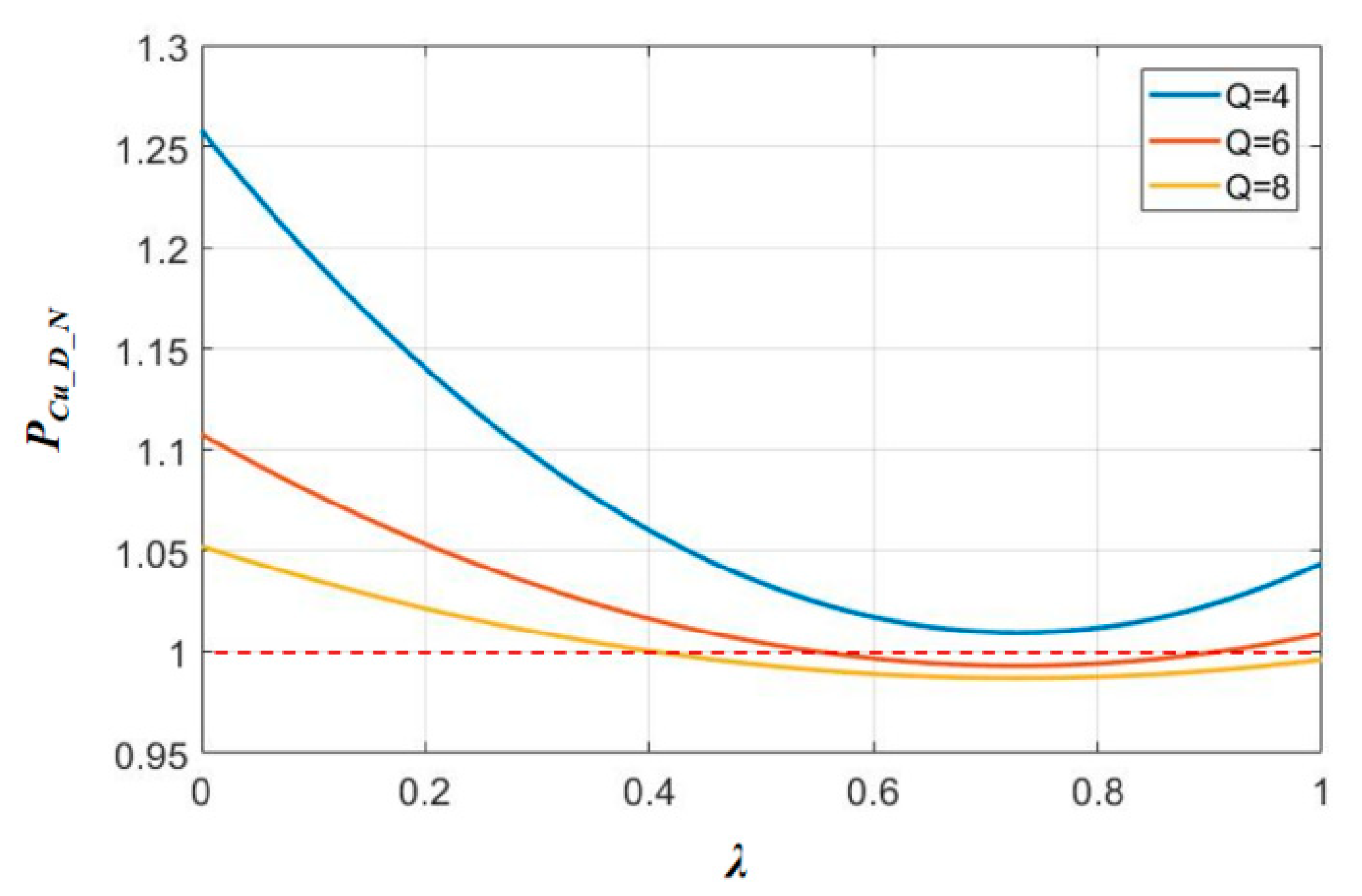
P C u _ D _ N = P C u _ D P C u _ S = 18 λ 2 R p 1 + 2 [ ( 1 λ ) δ ] 2 R p 3 + 4.5 Q 2 ( R s 1 + R s 3 ) 9 ( R p 1 + Q 2 R s 1 )
According to the measured values Rp1 = 130 mΩ, Rp3 = 890 mΩ, Rs1 = 120 mΩ, Rs3 = 115 mΩ, δ = 1.88, the normalized winding loss is plotted in Figure 9 (the trend of the normalized winding loss curve is subject to change according to the variation of internal resistances of coils). In the region below PCu_D_N = 1, the winding loss of the dual-channel system is less than that in the single-channel system.

3. Experiment Verification

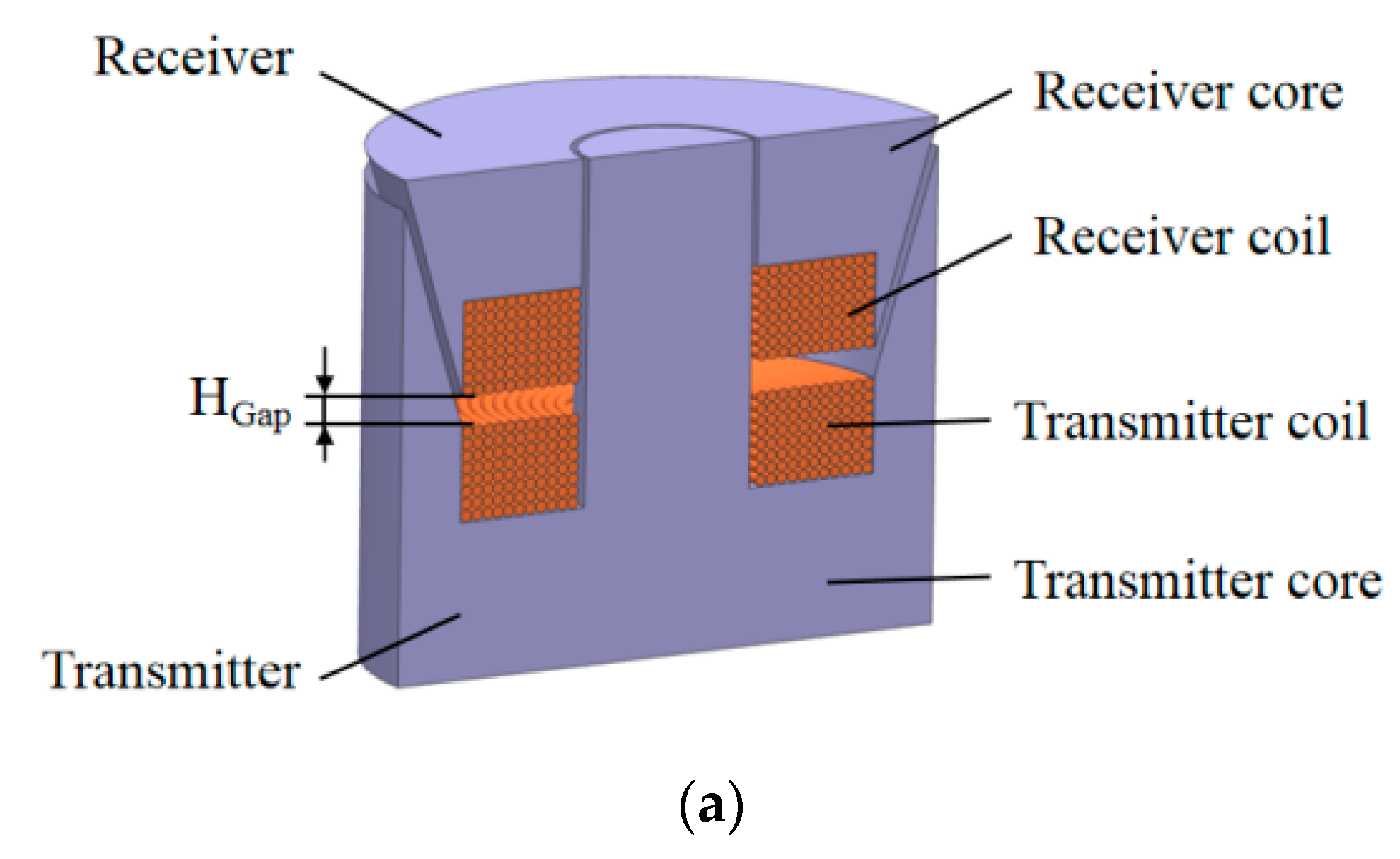
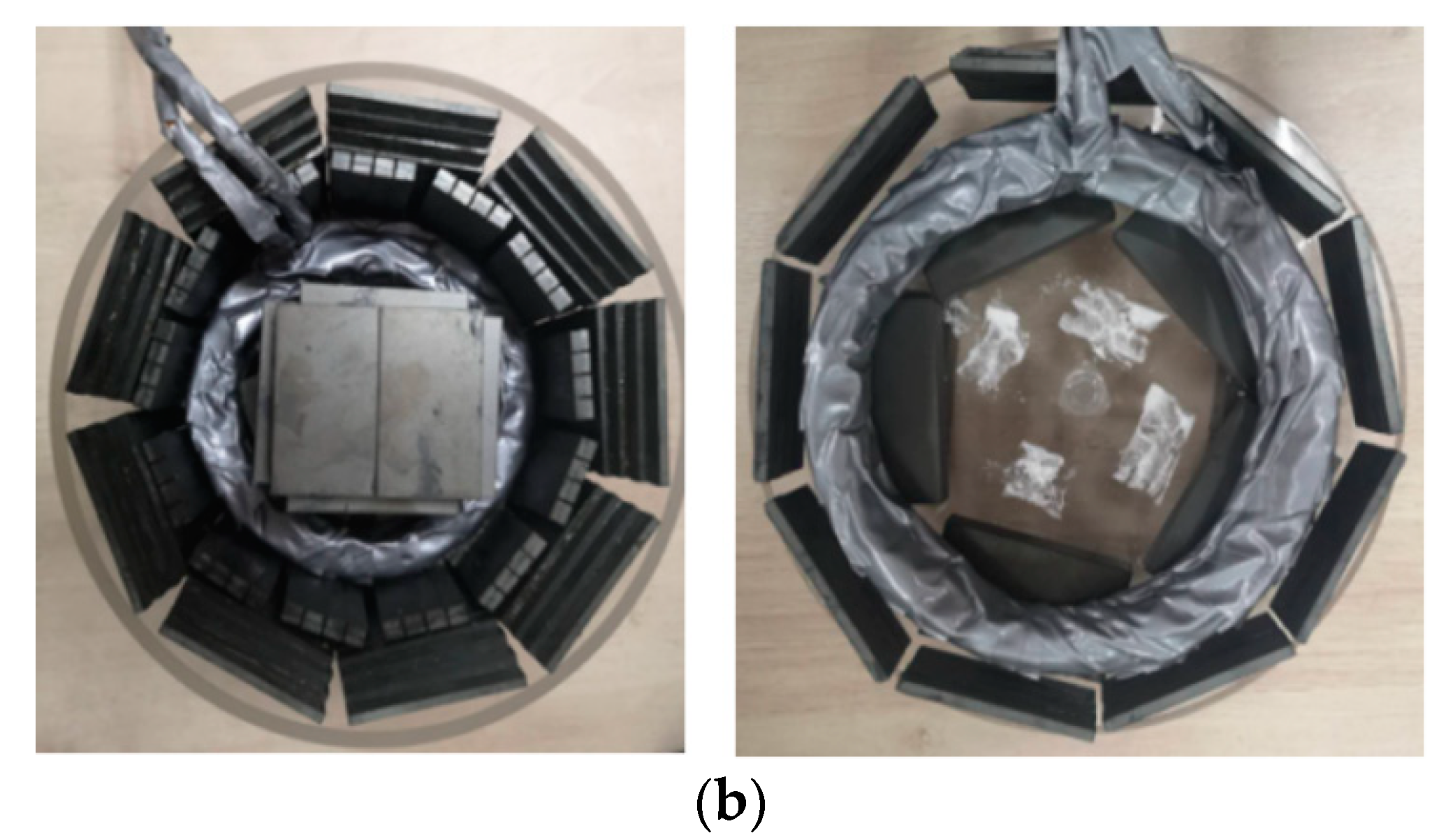
A 3 kW underwater wireless power transfer (UWPT) platform is established to verify the effectiveness of theoretical analysis. The schematic diagram of the proposed UWPT coupling structure is shown in Figure 10. The side column is designed with an incision angle to increase the contact area and to reduce the magnetic reluctance. Meanwhile, the proposed coupler also has the self-latching function once the transmitter and receiver get to the aligned position, which facilitates its resistance to ocean current disturbance (design and optimization of the coupling structure can be found in [28]). When the underwater vehicle lands on the base station, the receiver is plugged into the transmitter; thus in the charging process, the transmitter and receiver would remain in the fixed position. DMR95 material is utilized as the ferrite core. The gap between transmitter and receiver side varies between 5 and 20 mm, as the waterproof coating is applied on the coupler’s surface; the gap of 5 mm is the thickness of the waterproof coating, and the effects of seawater as transmission medium are reduced to a minimum. The couplers are shown in Figure 10. The experimental platform is shown in Figure 11. The experimental setup is shown in Table 1.
The influence of the strong coupling condition on system performance was first investigated on a single channel system. When the load resistance is 50 Ω, the inverter output voltage and current waveform are shown and compared in Figure 12. The component of the fundamental wave and third harmonic is then calculated and demonstrated in Table 1. As the coupling coefficient increases from 0.52 to 0.82, the inverter current waveform distortion worsens and the component of third harmonic increases from 6.72% to 48.56%, which means the component of harmonic increases as the increase of coupling coefficient, which agrees with the theoretical analysis.
Based on the single-channel UWPT system, an additional set of coils were added on the receiver side, which shares the same ferrite core with the original coil. The schematic diagram of the fundamental-harmonic dual-path wireless power transfer system is shown in Figure 5. DC power source provides power into the inverter before feeding into the compensation network together with the LC resonant tank. The two receiver coils pick up the power individually, and through the compensation network and rectifier on the receiver side, energy is provided to the load. The output of two receiver networks connects in series. The key parameters of the proposed dual-channel system are shown in Table 2. As few inductance elements were added for dual-frequency resonant network, and the high work frequency can effectively reduce the inductance volume, independent inductance was utilized.
The key waveform of dual-channel UWPT system is shown in Figure 13. The current in the primary coil is composed of fundamental wave and third harmonic, which proves the dual-frequency resonant characteristic of the transmitter network. The current in Channel 1(Ls1 and Cs1) only has the fundamental wave, and the current in Channel 2(Ls2 and Cs2) only has the third harmonic, which proves the frequency-selective characteristic of the receiver compensation network.
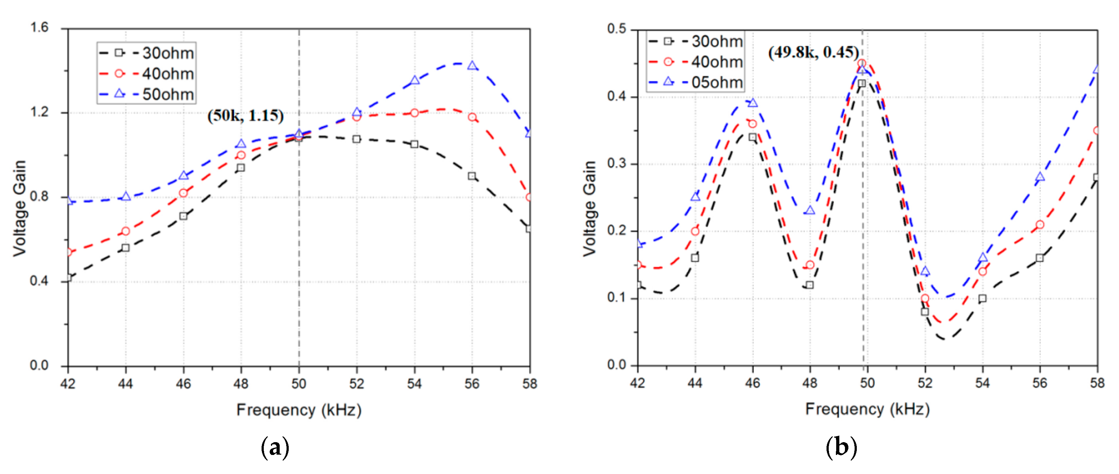
The frequency sweeping curve of system voltage gain is plotted in Figure 14. The crossing point in Channel 1 is right on 50 kHz and the voltage gain is 1.15. Meanwhile, the crossing point in Channel 2 is right on 49.8 kHz and the voltage gain is 0.45. The resonant frequency in Channel 2 is 49.8 × 3 = 149.4 kHz. The third harmonic of the inverter output is the input signal into Channel 2.
The maximum power transfer curves of the single- and dual-channel systems are compared in Figure 15, and the dual-channel system’s DC-DC efficiency is plotted in Figure 16 and compared with that of the single-channel system (both theoretically and experimentally). For the dual-channel system, the output power equals the output voltage multiplied by output current ( P O = U O I O ). The DC-DC efficiency in this paper is defined as the ratio of output power to input power ( η = | U o I o / U i n I i n | × 100 % ). The dual-channel system possesses higher energy output capability, with higher transmission efficiency. As the load resistance increases, the output power increases first before decreasing. When the output power is 2.69 kW, the system efficiency reaches its maximum value, 92.3%. Utilizing the experimental parameters in equations to calculated total output power and efficiency at specific load conditions RL = 30, 40, 50, 60 Ω, the theoretical values are plotted and compared with experimental results in Figure 15 and Figure 16.

4. Conclusions

For the underwater WPT system, the distance between transmitter and receiver is very small, which results in tight coupling between the transmitter and receiver. The system output characteristics under the tight coupling condition were analyzed based on the calculation of input impedance. The tight coupling condition provided a low impedance loop for high-order harmonic, which significantly increased the component of harmonics in UWPT. In order to fully utilize the harmonic energy, a fundamental-harmonic dual-channel system was proposed and studied in this paper. An LC stepped structure was applied on the primary side, and the combination of multiple resonant networks enabled the system to have multiple resonant frequencies. An additional LC compensation network was added on the secondary side to decouple the two receiver coils. The power transmission capability of the dual-channel system surpassed that of the single-channel system. The dual-channel system was compared with single-channel system in loss and efficiency. As to the rectifier conduction loss and winding loss, the loss in the dual-channel system was less than that of the single-channel system when the power factor was within a certain range. Theoretical analysis was then validated on a 3 kW underwater wireless power transfer platform. Maximum DC-DC efficiency of 92.3% was achieved. The dual-channel system has a better output characteristic compared with the single-channel system in underwater applications.

Author Contributions

Conceptualization, J.Z. and P.Y.; methodology, J.Z. and P.Y.; validation, J.Z., P.Y. and K.G.; formal analysis, J.Z., R.H. and P.Y.; investigation, K.G.; resources, Y.Z.; writing—original draft preparation, J.Z. and P.Y.; writing—review and editing, J.Z.; supervision, H.M.; project administration, J.Z. All authors have read and agreed to the published version of the manuscript.

Funding

This research was funded by Zhejiang R&D Key Research Plan, grant number 2019C01044 and by Zhejiang Natural Science Foundation, grant number LY18E070004.

Institutional Review Board Statement

Not applicable.

Informed Consent Statement

Not applicable.

Data Availability Statement

Not applicable.

Conflicts of Interest

The authors declare no conflict of interest.

References

  1. Benedetto., A.; Luca, P.; Alberto, R.; Fabio, C. Wireless power recharge for underwater robotics. In Proceedings of the 2017 IEEE International Conference on Environment and Electrical Engineering and 2017 IEEE Industrial and Commercial Power Systems Europe (EEEIC/I&CPS Europe), Milan, Italy, 6–9 June 2017; pp. 1–6. [Google Scholar]
  2. Kan, T.; Zhang, Y.; Yan, Z.; Mercier, P.; Mi, C. A Rotation-Resilient Wireless Charging System for Lightweight Autonomous Underwater Vehicles. IEEE Trans. Veh. Technol. 2018, 67, 6935–6942. [Google Scholar] [CrossRef]
  3. Kan, T.; Mai, R.; Mercier, P.; Mi, C. Design and analysis of a three phase wireless charging system for lightweight autonomous underwater vehicles. IEEE Trans. Power Electron. 2018, 33, 6622–6632. [Google Scholar] [CrossRef]
  4. Lin, M.; Li, D.; Yang, C. Design of an ICPT system for battery charging applied to underwater docking systems. Ocean Eng. 2017, 145, 373–381. [Google Scholar] [CrossRef]
  5. Hui, S.Y.R.; Zhong, W.; Lee, C.K. A Critical Review of Recent Progress in Mid-Range Wireless Power Transfer. IEEE Trans. Power Electron. 2014, 29, 4500–4511. [Google Scholar] [CrossRef] [Green Version]
  6. Mi, C.C.; Buja, G.; Choi, S.Y.; Rim, C.T. Modern Advances in Wireless Power Transfer Systems for Roadway Powered Electric Vehicles. IEEE Trans. Industrial Electron. 2016, 63, 6533–6545. [Google Scholar] [CrossRef]
  7. Zhang, C.; Lin, D.; Tang, N.; Hui, S.Y.R. A Novel Electric Insulation String Structure with High-Voltage Insulation and Wireless Power Transfer Capabilities. IEEE Trans. Power Electron. 2018, 33, 87–96. [Google Scholar] [CrossRef]
  8. Zhong, W.X.; Hui, S.Y.R. Maximum Energy Efficiency Tracking for Wireless Power Transfer Systems. IEEE Trans. Power Electron. 2015, 30, 4025–4034. [Google Scholar] [CrossRef] [Green Version]
  9. Zhang, C.; Lin, D.; Hui, S.Y.R. Ball-Joint Wireless Power Transfer Systems. IEEE Trans. Power Electron. 2018, 33, 65–72. [Google Scholar] [CrossRef]
  10. Zhang, K.; Ma, Y.; Yan, Z.; Di, Z.; Song, B. Eddy Current Loss and Detuning Effect of Seawater on Wireless Power Transfer. IEEE J. Emerg. Sel. Top. Power Electron. 2018, 8, 909–917. [Google Scholar] [CrossRef]
  11. Zhang, K.; Zhu, Z.; Du, L.; Song, B. Eddy loss analysis and parameter optimization of the WPT system in seawater. J. Power Electron. 2018, 18, 778–788. [Google Scholar]
  12. Yan, Z.; Song, B.; Zhang, K.; Wen, H.; Mao, Z.; Hu, Y. Eddy current loss analysis of underwater wireless power transfer systems with misalignments. AIP Adv. 2018, 8, 101421. [Google Scholar] [CrossRef] [Green Version]
  13. Zhang, Y.; Kan, T.; Yan, Z.; Mao, Y.; Wu, Z.; Mi, C. Modeling and analysis of series-none compensation for wireless power transfer system with a strong coupling. IEEE Trans. Power Electron. 2019, 34, 1209–1215. [Google Scholar] [CrossRef]
  14. Jolani, F.; Yu, Y.; Chen, Z. Enhanced planar wireless power transfer using strongly coupled magnetic resonance. Electron. Lett. 2015, 51, 173–174. [Google Scholar] [CrossRef]
  15. Ho, S.L.; Wang, J.; Fu, W.N.; Sun, M. A Comparative Study between Novel Witricity and Traditional Inductive Magnetic Coupling in Wireless Charging. IEEE Trans. Magn. 2011, 47, 1522–1525. [Google Scholar] [CrossRef]
  16. Zhang, Y.; Yan, Z.; Kan, T.; Liu, Y.; Mi, C.C. Modelling and analysis of the distortion of strongly-coupled wireless power transfer systems with SS and LCC–LCC compensations. IET Power Electron. 2019, 12, 1321–1328. [Google Scholar] [CrossRef] [Green Version]
  17. Ahn, D.; Kiani, M.; Ghoyanloo, M. Enhanced Wireless Power Transmission Using Strong Paramagnetic Response. IEEE Trans. Magn. 2014, 50, 96–103. [Google Scholar] [CrossRef] [Green Version]
  18. Wang, J.; Ho, S.L.; Fu, W.; Kit, C.T.; Sun, M. Finite-Element Analysis and Corresponding Experiments of Resonant Energy Transfer for Wireless Transmission Devices. IEEE Trans. Magn. 2011, 47, 1074–1077. [Google Scholar] [CrossRef]
  19. Sun, T.; Xie, X.; Li, G.; Gu, Y.; Deng, Y.; Wang, Z. A Two-Hop Wireless Power Transfer System with an Efficiency-Enhanced Power Receiver for Motion-Free Capsule Endoscopy Inspection. IEEE Trans. Biomed. Eng. 2012, 59, 3247–3254. [Google Scholar]
  20. Huh, S.; Ahn, D. Two-Transmitter Wireless Power Transfer with Optimal Activation and Current Selection of Transmitters. IEEE Trans. Power Electron. 2018, 33, 4957–4967. [Google Scholar] [CrossRef]
  21. Kim, Y.J.; Ha, D.; Chappell, W.J.; Irazoqui, P.P. Selective wireless power transfer for smart power distribution in a miniature-sized multiple-receiver system. IEEE Trans. Ind. Electron. 2016, 63, 1853–1862. [Google Scholar] [CrossRef]
  22. Zhao, C.; Costinett, D. GaN-based dual-mode wireless power transfer using multifrequency programmed pulse width modulation. IEEE Trans. Ind. Electron. 2017, 64, 9165–9176. [Google Scholar] [CrossRef]
  23. Ahn, D.; Mercier, P.P. Wireless power transfer with concurrent 200-kHz and 6.78-MHz operation in a single-transmitter device. IEEE Trans. Ind. Electron. 2016, 31, 5018–5029. [Google Scholar] [CrossRef]
  24. Pantic, Z.; Lee, K.; Lukic, S.M. Multifrequency inductive power transfer. IEEE Trans. Power Electron. 2014, 29, 5995–6005. [Google Scholar] [CrossRef]
  25. Liu, F.; Yang, Y.; Ding, Z.; Chen, X.; Kennel, R.M. A multifrequency superposition methodology to achieve high efficiency and targeted power distribution for a multiload MCR WPT system. IEEE Trans. Power Electron. 2018, 33, 9005–9016. [Google Scholar] [CrossRef]
  26. Liu, F.; Yang, Y.; Ding, Z.; Chen, X.; Kennel, R.M. Eliminating cross interference between multiple receivers to achieve targeted power distribution for a multi-frequency multi-load MCR WPT system. IET Power Electron. 2018, 11, 1321–1328. [Google Scholar] [CrossRef]
  27. Peng, F.Z.; Su, G.J.; Tolbert, L.M. A Passive Soft-Switching Snubber for PWM Inverters. IEEE Trans. Power Electron. 2004, 19, 363–370. [Google Scholar] [CrossRef]
  28. Zhou, J.; Yao, P.; Chen, Y.; Guo, K.; Hu, S.; Sun, H. Design Considerations for a Self-latching Coupling Structure of Inductive Power Transfer for Autonomous Underwater Vehicle. IEEE Trans. Ind. Appl. 2020, 57, 580–587. [Google Scholar] [CrossRef]
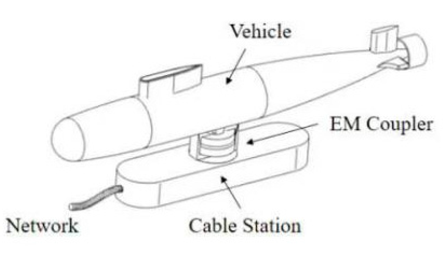
Figure 1. Underwater wireless power transfer system.
Energies 14 00242 g001
Figure 2. Mutual inductance model: (a) S-S compensated wireless power transfer syste, (b) impedance model of S-S compensated WPT system.
Energies 14 00242 g002
Figure 3. Component of the third harmonic with variation of coupling coefficient.
Energies 14 00242 g003
Figure 4. Fundamental-harmonic dual-path wireless power transfer.
Energies 14 00242 g004
Figure 5. Dual-resonant-frequency wireless power transfer system.
Energies 14 00242 g005
Figure 6. Compensation networks: (a) LCL, (b) dual resonant frequency network.
Energies 14 00242 g006
Figure 7. Normalized dual-channel input current.
Energies 14 00242 g007
Figure 8. Equivalent circuit of the dual-channel system.
Energies 14 00242 g008
Figure 9. Equivalent circuit of the dual-channel system.
Energies 14 00242 g009
Figure 10. Proposed coupler structure: (a) basic structure; (b) prototype.
Energies 14 00242 g010aEnergies 14 00242 g010b
Figure 11. Experiment platform.
Energies 14 00242 g011
Figure 12. Inverter output voltage and current waveform under different coupling factors: (a) k = 0.52; (b) k = 0.61; (c) k = 0.71; (d) k = 0.82.
Energies 14 00242 g012aEnergies 14 00242 g012b
Figure 13. Key waveform of the dual-channel UWPT (under water wireless power transfer) system: (a) inverter output voltage and current; (b) current in primary and secondary coils.
Energies 14 00242 g013
Figure 14. Frequency sweeping curve of system voltage gain in (a) Channel 1; (b) Channel 2.
Energies 14 00242 g014
Figure 15. Maximum power transfer curve comparison of the single- and dual-channel systems.
Energies 14 00242 g015
Figure 16. System DC-DC efficiency.
Energies 14 00242 g016
Table 1. Component third harmonic as a variation of coupling coefficient.
k0.520.610.710.82
IP_3/IP_1 (%)6.7210.6422.3948.56
Table 2. Parameters of the dual-channel system.
ParametersLA/μHLB/μHLp/μHLs1/μHLs2/μHCA/nF
Value106.179.6254.87252.9949.0131.8
ParametersCB/nFCs1/nFCs2/nFLr1/μHLr2/μHCr1/nF
Value42.436.826.3205056.3
ParametersCr2/nFf/kHzMps1/μHMps2/μHMs12/μHRL/Ω
Value202.650200.08106.4192.3450
Publisher’s Note: MDPI stays neutral with regard to jurisdictional claims in published maps and institutional affiliations.