Article

Modelling Carbon Corrosion during a PEMFC Startup: Simulation of Mitigation Strategies

1
LITEN, CEA, Univ. Grenoble Alpes, F-38054 Grenoble, France
2
LEPMI, Grenoble INP, CNRS, Univ. Savoie Mont Blanc, F-38000 Grenoble, France
*
Author to whom correspondence should be addressed.
Energies 2020, 13(9), 2338; https://doi.org/10.3390/en13092338
Submission received: 12 March 2020 / Revised: 7 April 2020 / Accepted: 16 April 2020 / Published: 8 May 2020
(This article belongs to the Special Issue Polymer Electrolyte Membrane Fuel Cell Systems)

Abstract

:
This paper presents a study of the carbon support corrosion and mitigation strategies through the use of a pseudo-3D model. This model consists in coupling a 2D model along the channel with another model perpendicular to the flow at the rib/channel scale. Simulations offer a deeper understanding of the corrosion through the analysis of the local conditions. Rib/channel heterogeneities show the higher degradation in the zones facing the anodic rib. These results are validated qualitatively on literature data by analysis of SEM images and carbon dioxide concentration at the cathode outlet. Three mitigation strategies are studied using the model. The first one consists in speeding up the hydrogen filling of the cell. The second strategy involves an external electrical resistance to create a current leak during the startup. Third, a design study of the rib/channel is performed to minimize the cathode degradation. Whatever the mitigation strategy, it consists in reducing either the duration or the magnitude of the high cathode electrode potential.

Graphical Abstract

1. Introduction

For automotive application, the durability of fuel cells has to be improved. Current proton exchange membrane fuel cells (PEMFC) lifetime is around 4000 h, when 5000 h are expected for vehicle application [1]. Several degradations occur in the fuel cell and the carbon support corrosion inside the active layer is a key one. In the membrane-electrodes assembly (MEA), the catalyst layers (CL) are the location of the electrochemical reactions. They are composed of particles of platinum deposited on a carbon support and meshed with ionomer. The catalyst layer is a microporous structure which allows gas and liquid water transport [2]. Thus, carbon support degradation is responsible for a loss of active surface. Finally, if the support is too damaged, a collapse of the structure can be observed, making the catalyst layer inoperable.
The most severe conditions for carbon corrosion appear during startup or shutdown of the system [3]. The mechanisms involved have been well described by Reiser et al. [4]. During startup, a high cathode potential appears, inducing a significant carbon corrosion [3,4,5,6,7]. In a symmetrical way, the same effect can be observed during shutdown if the anode side is flushed with air.
At the cell scale, Durst et al. [8] highlighted that fuel starvation may accentuate a heterogeneous ageing of the cathode facing an anodic rib. Schneider et al. observed with current distribution mappings that significant in-plane currents are detected at the rib/channel scale [9]. Several models were proposed to give a better comprehension of this behaviour [4,5,7,10,11,12,13,14,15,16]. As reviewed by Gu et al. [17], several types of models can be used, depending on the physical phenomena accounted for: from electrochemical models involving a complex mechanism [4] to physic-based models including transport phenomena inside porous electrode and membrane [5,10]. Maranzana et al. [7] propose a “pseudo 2D” model simulating a transient startup during hydrogen feeding. The cell is discretized into twenty sections considering a 1D generic electrode model. This 1D model accounts for the complex electrochemical mechanism, including surface platinum reduction/oxidation as well as two carbon oxidation reactions. The mass transport equations are solved in the gas diffusion layers (GDL) as well as in the membrane. Namely the model takes into account the gases crossover through the membrane. Simulation results are compared to local currents measured by a segmented cell and the total amount of carbon oxidized. Moreover, reversible degradations are also taken into account by the platinum oxidation that create a pseudo-capacitive effect. Meyer et al. [5] proposed a model to describe how a maldistribution of hydrogen across the fuel electrode can induce both oxygen evolution and carbon corrosion on the positive electrode of the fuel cell in the fuel-starved region.
Several strategies can be used to mitigate the carbon corrosion. A review of these has been done by Zhang et al. [18]. On the one hand, as the carbon support undergoes harsh corrosion phenomena under frequent startup-shutdown cycles, it can be modified in order to be more stable. Highly resistant graphitized carbon has been proven effective to reduce the degradation compared with the standard carbon support [19] and limit the degradation during startup while improving the performance by dint of a more homogeneous distribution of Pt nanoparticles [20]. On the other hand, the development of mitigation strategies through system controls may limit the carbon corrosion during startup and shutdown. To overcome this challenge, researchers and companies (UTC, General Motors, Honda, etc.) proposed different solutions. Gas purge is one of the easiest strategies. It can either be hydrogen purge at the cathode [21], air purge at the anode [22] or nitrogen purge at the anode [23].
Finally, an auxiliary load allows mitigating the degradation by hindering the decrease of electro-chemical surface area (ECSA) [24,25]. In fact, this latter strategy limits the high potential achieved by the cathode and thus mitigates the carbon corrosion rate during a startup [9].
In this work, a modelling approach is proposed to evaluate the impact of the startup scenarios as well as the bipolar plate design on the carbon support corrosion. A transient pseudo 3D model is presented by coupling two different 2D models. Multiphysics transports coupled with electrochemical reactions are solved. Impact of the transport, especially diffusion in the channel and in the porous media is taken into account, as the hydrogen "front" may be smoothed by diffusion in the channel and in the GDL. Initially, the "anode" side of the cell contains only air. Then pure hydrogen is injected at the inlet, pushing the air out on the other side. A front is usually assumed in the modelling studies, where one part of the channel is pure air, whereas the other side contains pure hydrogen, the two regions been delimited by a front. As in reality, nothing prevents the gases from diffusing in each other and to mix, so instead of having a steep frontier, a region containing a mixture of air and hydrogen is expected to extend over time. The idea behind the model is to be able to simulate a fuel cell startup without further assumptions on the regions where the reactions occur or not. The model is not artificially segmented in the in-plane direction and the cell decomposition as proposed by [3] is expected to be an outcome of the simulations.
Three mitigation cases are then investigated in this work:
  • increasing the flow rates in the anode channel in order to remove as fast as possible the remaining oxygen during the startup and reduce the exposure time of the cathode to high potential [7,17,26];
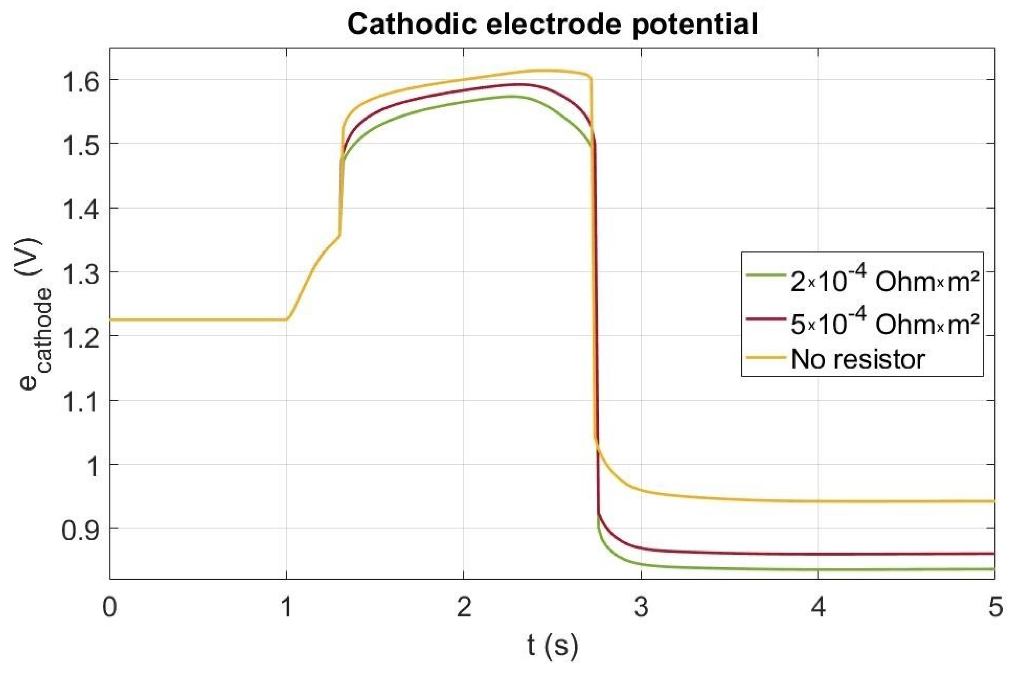
  • controlling the cathode electrode potential by using a current leak through a dummy load consisting of a parallel resistance [24];
  • changing the anodic rib/channel design in order to slow down the kinetic of the degradation of the cathode facing the rib. To our knowledge, no simulation studies were performed so far on the design of the bipolar plate as a way to mitigate the carbon corrosion during startup/shutdown.

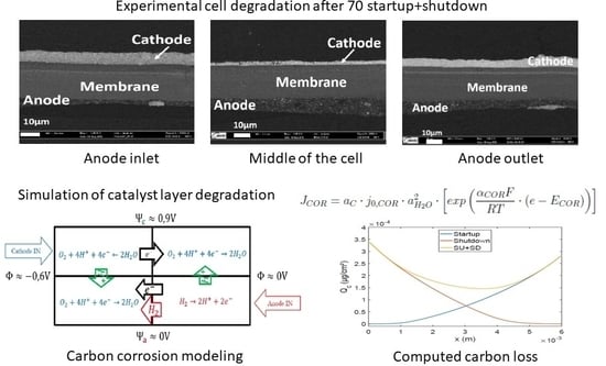
2. Dynamic Model of Carbon Support Corrosion during Startup

A pseudo 3D model based on previous work [27] is developed and used for the carbon corrosion modeling. Geometry of the model is presented in Figure 1, showing a section of a single channel cell integrating bipolar plate (BP), channels (CH), gas diffusion layers (GDL), catalyst layers (CL), and membrane (MB). For symmetry reasons, only the half of a channel is represented. The scales of the different zones are given in Table 1. The first model of our pseudo-3D approach describes the inlet-outlet heterogeneities along the channel length while the second one perpendicular to the gas flow focuses on the rib-channel effect. The fuel cell operates in a counter flow configuration for the pseudo-3D model. Channels and catalyst layers are not discretized in the direction perpendicular to the cell length. The transport of gas the species in the channels is described by the Stefan-Maxwell equations and a global pressure drop. The transport of species in porous media are modeled as in [27], using the approach proposed by Young and Todd [28] which basically allows coupling Stefan-Maxwell, Darcy and Knudsen transport phenomena. Charge transport equations are expressed by Ohm’s law. The comprehensive list of equations implemented in the model can be found in Appendix A.
All electrochemical reactions taken into account in the model are implemented at both catalyst layers (anode and cathode) without any assumption about their effective occurrence. The reaction rates are calculated as function of the local conditions which lead most of the time to a mixed equilibrium potential. At the same time and location, the oxygen reduction reaction (ORR) and the oxygen evolution reaction (OER) as well as the hydrogen evolution reaction (HER) and the hydrogen oxidation reaction (HOR) may take place:
2 H 2 O O 2 + 4 H + + 4 e
H 2 2 H + + 2 e
These reactions can be written in the general form [27]:
i ν i M i z i n e
where ν i and z i are respectively the stoichiometry and the charge coefficients of the specie M i and n, the number of electrons involved in the reaction. The reduction and oxidation currents are obtained from the local electrode potential expressed as e = Ψ Φ , where Ψ is the electronic potential (carbon/platinum phase) and Φ is the ionic potential (ionomer phase) in the catalyst layer:
i o x = n F k o x 0 ν i > 0 a i ν i · e x p α n F R T e i r e d = n F k r e d 0 ν i < 0 a i ν i · e x p ( 1 α ) n F R T e
where T is the temperature, R the universal gas constant, α the symmetry factor of the reaction, F the Faraday constant and a i the activity of specie i. The kinetic factors are written [27]:
k o x 0 = k 0 e x p Δ G o x R T k r e d 0 = k 0 e x p Δ G r e d R T
where Δ G = Δ H T Δ S is the free activation enthalpy (computed from the activation enthalpy en entropy Δ H and Δ S ) and where k 0 is a kinetic “’constant” (it still depends on temperature) calculated with the Eyring’s equation:
k 0 = k b T s 0 N A h
where h is the Planck constant, k b , the Boltzmann constant, s 0 the Pt surface per reaction site and N A the Avogadro constant. Table 1 lists the electrochemical parameters for the simulations.
The corrosion model is build upon this performance model [27] adding the oxidation reaction of the carbon support (COR):
C + 2 H 2 O CO 2 + 4 H + + 4 e
Literature suggested several mechanisms to explain the corrosion of the carbon support. Most of them highlight the impact of platinum oxides on the corrosion mechanism [30,31]. As our paper mainly focuses on mitigation strategies, the study of the corrosion mechanism is beyond the scope of this work. For the sake of simplicity, a global carbon corrosion kinetic is used, as proposed by Gu [17]:
J C O R = a C · j 0 , C O R · a H 2 O 2 · e x p α C O R F R T e E C O R
a C being the specific surface of carbon and E C O R , the apparent potential of corrosion defined as a function of the water activity ( a H 2 O ):
E C O R = E C / C O 2 0 R T n F · l o g a H 2 O 2
As the carbon corrosion reaction (7) is considered to be largely irreversible, the equilibrium potential and kinetics do not depend on the pH and the CO 2 activity.

3. Simulation of the Transient Potentials and the Resulting Carbon Support Corrosion during Startup

The two models are used in conjunction in order to simulate the startup and the resulting degradation at different scales (cell inlet/outlet and rib/channel). Table 1 lists the geometrical parameters that have been used for this study. Operating conditions are described in Table 2. The fuel cell before the startup is filled with air at both anode and cathode sides. In the simulation of the startup, injection of the hydrogen occurs at t = 1 s and ascends to its nominal value in 0.1 s. Symmetrically, the supply of oxygen is stopped at the same time.

3.1. Along the Channel
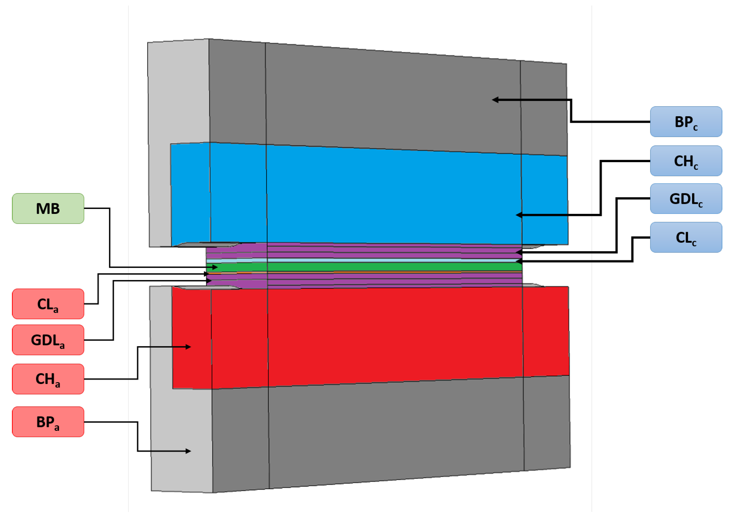
The gas concentrations in the anodic channel and the GDL at different times of a startup are shown in Figure 2. Figure 2a,b present the situation during hydrogen feeding at t = 1 s. In the channel, the concentration profiles are very abrupt close to the hydrogen gas inlet, but gas diffusion effect can be observed on the water vapor and oxygen gas profiles. Whatever the species, the gas concentrations are spreading as the startup is ongoing. For example, Figure 2c,e show that the hydrogen front is smoother than it was close to the inlet at the beginning of the startup. Figure 2d shows the hydrogen front in the GDL located close to the center of the gas channel at t = 2 s. According to the oxygen concentration profile, the electrochemical phenomenon leads to oxygen consumption on the right side of the cathode gas channel while oxygen production occurs on the left side. Moreover, Figure 2f exhibits the gas concentrations re-homogenization in the porous media at the end of the startup. These local gases concentrations at the catalyst layer interface enforce the local electrode potentials at the anode and cathode (Figure 3).
During the startup, the potentials of the anode and cathode along the electrode catalyst layer length are shown in Figure 3. A sudden electrode potential drop, moving from the right to the left, is predicted during the startup (see profiles at t = 1.6, 1.9, 2.2 and 2.5 s) because of the hydrogen front displacement. As stated in the introduction and predicted by our simulations, two zones can be distinguished by a sudden electrode cathode potential drop (see Figure 3) due to the low in-plane ionic conduction in the membrane. It can be noted that even if the gas concentration profiles are smoothed, the potential front remains very stiff all along the startup. As the cathode potential ranges from 0.83 V up to 0.9 V at the right side (Figure 3), the OER takes place at the left side owing to the cathodic electrode potential being higher than 1.4 V, while the ORR happens at the right side. At the anode (Figure 3b), the ORR occurs at the left side due to the anodic electrode potential changes from 0.75 V to 0.85 V while HOR happens at the right side of the front where the potential is lowered around 0.05 V.
The current densities of OER as well as carbon corrosion are presented in Figure 4a at different locations of the cathode catalyst layer during startup. Indeed, the current associated with the OER is handed out at the left of the front while the one referred to ORR is distributed at the right side. It is worth mentioning that current density for the OER is lower than the ORR one because of the higher surface available for this reaction as soon as the front appears. As the front is going from the anode inlet to the outlet, the ORR current density declines while the OER one is rising. Figure 4b shows the particular profile of COR current density which is clearly related to the front location. Indeed, the closer to the cathode inlet is the front, the higher the corrosion current density is, inducing a higher degradation close to the cathode inlet. This can be explained by the smaller the surface where the OER occurs. The high resulting current density leads to very high cathode potential (>1.6 V) at the end of the startup near the cathode inlet, which causes severe corrosion.
Indeed Figure 5a presents the forecasted distribution of cumulative carbon loss at different locations of the cathode gas channel during a startup in counter flow. According to the corrosion current density distribution (Figure 4a), an asymmetrical loss distribution is observed. The degradation is the most important near the cathode inlet (on the left) and decreases to be zero at the cathode outlet (on the right). Qualitatively, the model is validated using scanning electron microscopy (SEM) images from [8], where the degradation of the catalyst layer is observed through the decrease of its thickness. Those images show that the cathode catalyst layer is more degraded near the cathode inlet than the middle and the cathode outlet. At the cathode outlet, no carbon corrosion occurs which can be observed in [8] where the thickness of the catalyst layer does not change (compared to the pristine).
To further validate the model, the CO2 concentration at the cathode channel outlet is calculated (Figure 5b). The simulation predicts a maximal value of 75 ppm in agreement with the 100 ppm measured by Gu et al. [17] in similar conditions.

3.2. Rib/Channel

While the previous model presents the degradation along the gas flow, a coupling with the rib/channel model (perpendicular to the gases flow, see [27] for the detailed geometry) is used to investigate carbon corrosion at the rib/channel scale. An effect is expected at this scale, due to hydrogen diffusion in the GDL. Indeed, hydrogen does not arrive at the same time under the rib or under the channel, leading to heterogeneities in carbon corrosion between rib and channel [8,9]. Namely when hydrogen is supplied at the anodic catalyst layer under the channel, same mechanisms as the along the channel are expected to occur. So, hydrogen oxidation and oxygen reduction occurs under the anodic channel while oxygen reduction and water oxidation takes place under the anodic rib. Indeed, because of hydrogen diffusion under the anodic rib, local fuel starvation occurs creating an hydrogen front perpendicular to the one coming along the channel. Simulations have been performed at the cathode inlet (which corresponds to anode outlet) where degradation is the most important. A parallel flow configuration is assumed in channels meaning that hydrogen is supplied simultaneously at each side of the rib. A parameter Γ is defined as the anode rib width to total gas+channel width ratio [27]. It is fixed at 50 % by default and corresponds to a anode rib width of 1.1 mm and a gas channel width of 1.1 mm too (see Table 1). As explained in the previous subsection, the cathode electronic potential is modified when hydrogen is fed to the anode inlet and thus the profile predicted by the along the channel model (see Figure 3) is used as input in the rib/channel model. The same coupling is used for the concentrations at the anode channel/GDL boundary. The cathode potential during startup along the rib and channel is then calculated. Figure 6 shows the cathode electrode potential in the plane of the catalyst layer close to the cathode inlet during a startup. In Figure 6, two different zones have to be distinguished: the CCL facing to the anodic rib in the middle (grey color) and the CCL facing to the anodic gas channel on the left and on the right sides. Before the arrival of hydrogen at the anode outlet (at t = 2 s), high and homogeneous cathode potential (over 1.5 V) is observed (blue curve). When the H 2 front arrives at the anode outlet (facing the cathode inlet), hydrogen reaches first the anode catalyst layer in front of the channel (green curve) while its diffusion under the rib is delayed, so a small cathode potential heterogeneity is induced with a higher potential in the area facing the anode rib and a lower potential in the area facing the anode gas channel. This heterogeneity grows as hydrogen fills the anode GDL and a strong heterogeneity is observed at the end of the startup as shown by the red curve (at t = 2.76 s). Indeed, as hydrogen transport is slower under the rib than under the channel, the cathode potential then drops first in the zone facing the anode gas channel until hydrogen diffuses under the rib homogenizing the potential at the cathode. When the anode side is filled by hydrogen, including the area under the rib, the cathode potential drops under 1 V (turquoise curve), which corresponds to nominal operating conditions of the cell after the startup. Indeed, the higher CCL potential under the anodic rib may cause a higher carbon corrosion in this area.
Figure 6b displays the simulated distribution of cumulative carbon loss in the catalyst layer along the rib/channel direction during a startup. In accordance with the cathode potential distribution along the rib/channel (Figure 6a), corrosion is significantly higher ( 10 % more) in the area facing the anode rib than in the areas facing the anode channel. This is validated by SEM experiments performed by Durst et al. [8] showing thinner cathode catalyst layer in the zone facing the anodic rib.

4. Mitigation Strategies Simulation

Using the model presented in the previous sections, carbon corrosion mitigation strategies are simulated and evaluated. Two main levers are tested: the first one consists in limiting the time elapsed in corrosion while the second one consists in reducing the cathode potential.

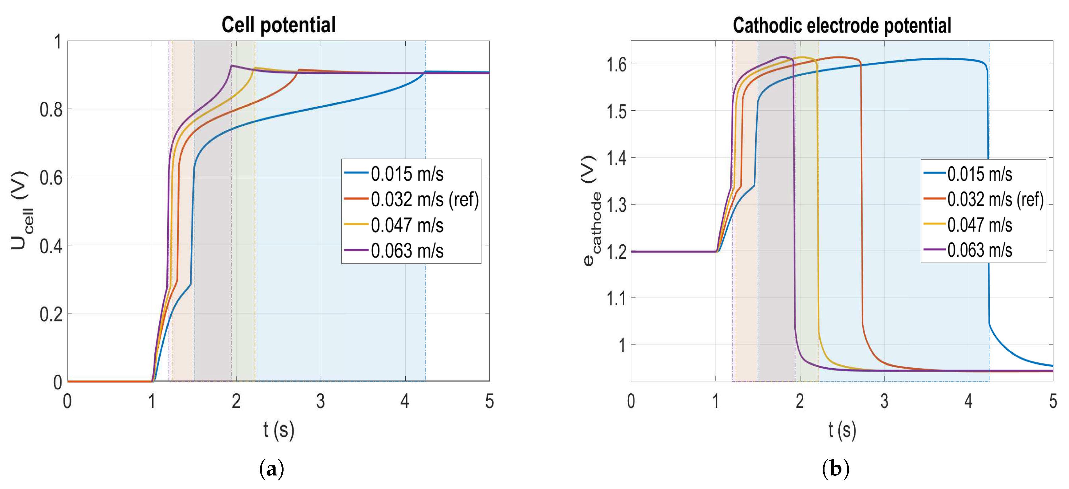
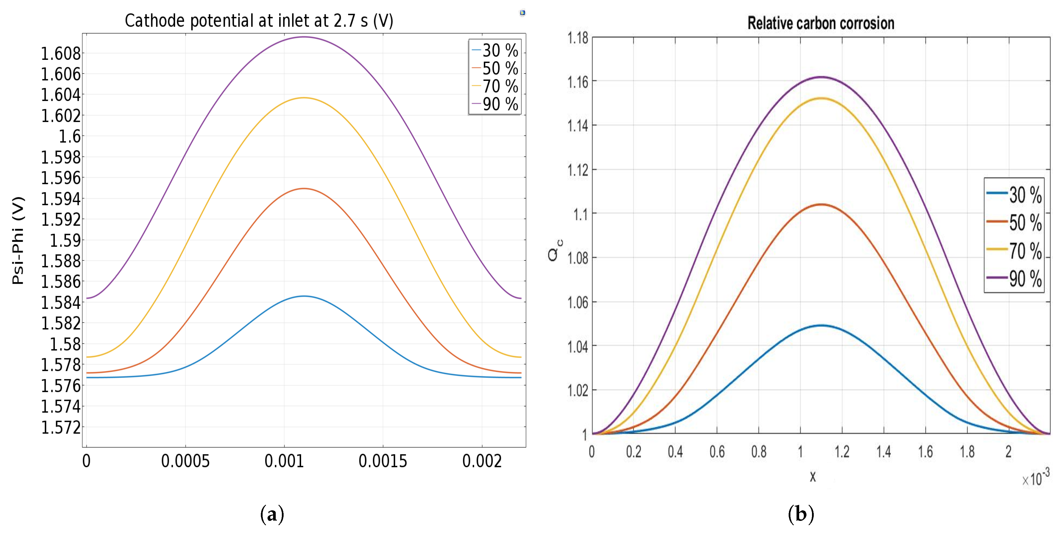
4.1. Gas Flow Velocity

The previous section shows that the corrosion occurs during the filling of the anode compartment by the hydrogen. By speeding up this filling, corrosion is expected to be lowered. Four speeds of H 2 flow are tested: 0.015 m/s (marine blue curve), 0.032 m/s (red curve), 0.047 m/s (yellow curve) and 0.063 m/s (purple curve). Please note that the value of 0.032 m/s is the reference speed used in the simulations (see Section 3). Figure 7 displays the cell potential as well as the cathodic electrode potential for the four different anode flow velocities during a startup. Looking at the reference case (red), the cell potential rises over 0.6 V after injection of the hydrogen when it reaches the anode catalyst layer. Finally, after 2.7 s the hydrogen front exits from the cell which causes the cell potential to reach a maximum over 0.9 V before decreasing to reach the final OCV value. For the slowest velocity, the duration of the startup ( 3.2 s) is approximately two times longer than the reference case which lasts 1.7 s. The potential overshoot at the end of each startup is lowered when the velocity declines, demonstrating the impact of the profile of the front.
According to the cathode electrode potential profile in Figure 7b, the time elapsed in corrosion for each case (given in Table 3 and illustrated by the coloured areas in Figure 7) is inversely proportional to the flow velocity. Indeed, it corresponds to the time during while the fuel cell undergoes the reverse current mechanism. As expected, the flow velocity has a proportional effect on the time during which the fuel cell undergoes the reverse current mechanism. Nonetheless, the maximal value of the potential achieved in each case is slightly different which may explain the non-linear variation of the total amount of carbon loss as a function of time spent in corrosion regime.
The total quantity of carbon corroded as function of the flow velocity at the anode is summarized in Table 3. It is worth nothing that the higher the velocity, the lesser the carbon is corroded. The impact is amplified mainly near to the cathode inlet where the carbon corrosion is favored. Compared to the reference case, the slowest speed leads to an increase of carbon corrosion from 0.08 μ g C /cm 2 to 0.14 μ g C /cm 2 corresponding to a carbon loss increase of 76%. On the contrary the fastest speed (twice faster than the reference case) highlights a decrease of 48.5% of carbon loss with 0.042 μ g C /cm 2 . The corrosion mitigation obtained by speeding up this filling tends to slow down because of the limitation induced by the hydrogen transport in the GDL. Finally, from the amount of carbon corroded and the catalyst layer composition, it is possible to estimate the catalyst thickness reduction, assuming that the thickness loss is proportional to the carbon loss.

4.2. Startup with a Current Leak

The cathode electrode potential can be lowered by creating a current leak using a resistance during the startup [7,24]. In our simulation, a current leak through a resistance is only performed when the cell voltage is higher than 0.5 V in order to avoid any current leak if not necessary and before the cell is fed with hydrogen. Nevertheless, the current leak allows reducing both the cell voltage and the cathode electrode potential during the startup (red and green curves in Figure 8) by comparison to the case without a resistor. In an actual system, the resistance should of course be interrupted as the startup is finishing. Though effect of the resistance on the cell voltage is very low, Figure 8 shows that it affects significantly the cathode potential. Before t = 1.3 s, as the cell potential is lower than 0.5 V, the current leak is no activated. During the startup (from t = 1 s to 2.3 s), the cathode electrode potential rises from 1.23 V up to a value higher than 1.6 V without a resistor and lower than 1.5 V with a resistor (both cases). Beyond 2.3 s, the potential decreases down to 1.5 V just before the brutal drop indicating the end of the startup phase. For the both resistances, the simulated cathode potential increase is far lower than the one without resistor. This latter is due to the current leak consuming the remaining oxygen in the anode catalyst layer. As the current leak increases when decreasing the resistor, the carbon corrosion should be lesser when decreasing the value of the resistor. Indeed, the cumulative carbon losses with and without the resistance were also computed. Only 0.03 μ g C /cm 2 and 0.045 μ g C /cm 2 are corroded with both resistances ( 2 × 10 4 Ω · m 2 and 5 × 10 4 Ω · m 2 respectively) compared to the 0.08 μ g C /cm 2 without resistance, which corresponds to a drop of around 63% of carbon corroded for the lower resistor and about 43% for the higher value.

4.3. Impact of Rib-Channel Design

The effect of the anode rib to total width ratio Γ from 30% to 90% is finally investigated. Figure 9a shows the cathode electrode potential at t = 2.7 s at the cathode inlet when it reaches its higher value (see Figure 6). It can be observed that an increase of the anode rib width from 0.6 mm up to 1.8 mm leads to an increase of the cathode potential facing the anodic rib, causing an increase of the carbon corrosion in this area. Furthermore, the cathode electrode potential profile is less homogeneous for the larger anode rib exhibiting the impact of the bipolar plate design. It can be noted that the increase of the cathode potential in the area facing the anodic rib (middle of the image) is not proportional to the increase of the ratio.
Figure 9b displays the relative corrosion variation along the cathode catalyst layer as function of the rib/total length ratio. Even if the cathode potential variations are small, impact on the carbon corrosion is significant. Due to the hindered hydrogen diffusion, higher corrosion occurs once the anode rib is the largest. For the smallest ratio, the corrosion is only 5 % more important in the area facing the anodic rib than the one facing the anodic channel, but it increases to more than 15 % for the largest ratio. The size of the rib has no significant impact on the corrosion when the rib/total length ratio is lower than 50%. So, the model predicts that a larger anodic rib enhances the carbon corrosion in the cathodic catalyst layer in front of the anodic rib even if better performances are obtained in this case [27]. Varying anodic rib width along the flow might be proposed to mitigate the local carbon corrosion during the startup without affecting too much the performance. Larger anodic ribs at the anode inlet can be used to improve performance whereas smaller anodic ribs at the anode outlet allows mitigating the carbon corrosion during startup.

5. Conclusions

Thanks to the use of a multiphysic and multiscale model, carbon corrosion and mitigation strategies have been investigated in this paper. Two scales of heterogeneities (2D along the channel and 2D cross-section) are used to integrate the carbon support corrosion mechanisms. The model captures the dynamic of the fuel cell startup and shutdown. A better understanding of the mechanisms occurring during startup is obtained and allows simulating phenomena such as the reverse current mechanism without forcing the model.
As expected in a counter-flow configuration, cathode inlet is more severely corroded because of the hydrogen front progressing in the anode compartment. The low in-plane ionic conduction in the membrane separates the cell in two very distinct regions which leads to high cathode potential near the cathode inlet. Simulation confirms that as the hydrogen front moves to the anode outlet, this high cathode potential steadily rises until the filling of the anode compartment is finished. The resulting potential is responsible for the degradation of the catalyst layer near the cathode inlet whereas the area near the cathode outlet shows no significant carbon corrosion. This is validated by SEM images in the literature [8]. The along the flow model is coupled with a rib/channel model in order to study heterogeneities at this local scale. Hydrogen transport under the anodic rib is shown as a factor for cathode potential heterogeneities between the area facing the anodic channel and the one facing the anodic rib. The latter shows higher cathode potential which leads to significantly more degradation.
This pseudo 3D-model is here implemented to evaluate different mitigation strategies and to propose an improved rib/channel design. Therefore, the model allows studying the impact of the gas velocity during the startup. By increasing the velocity, the hydrogen front responsible for the corrosion spends less time in the anode compartment leading to less degradation. An external resistance has been simulated in order to create a current leak that lowers the cathode potential. The effect of the current leak is shown to be significant on the electrode potential, strongly limiting the carbon corrosion. The total carbon loss can easily divided by two with this technique. Finally, the impact of rib to total size ratio is studied. The larger this ratio, the higher the carbon corrosion heterogeneity. While for a ratio of 30% the difference is around 5% between the corrosion occurring in the area facing the anodic rib and the one facing the channel rib, this difference can go to more than 15% for a ratio of 70%.
Shutdown simulation studies could also be performed with the model with some additions: as during shutdowns the impact of platinum oxides were proved important [7], surface oxides influence should be considered in this case. As the approach presented here is very generic, mainly for the electrochemical mechanisms taken into account, a more detailed description of the carbon corrosion kinetic and coupling with other degradation mechanisms, such as platinum dissolution and redeposition, is another option for future extensions of this model.

Author Contributions

Individual contributions are as follows: model development, B.R., P.S.; Simulations exploitation and analysis, B.R., P.S., M.G., Y.B.; writing—original draft preparation, B.R.; writing—review and editing, B.R., P.S., M.G., Y.B.; supervision, P.S., M.G., Y.B. All authors have read and agreed to the published version of the manuscript.

Funding

This research received no external funding.

Acknowledgments

This work has been achieved in the framework of the European ID-FAST project which has received funding from the Fuel Cells and Hydrogen 2 Joint Undertaking under the European Union’s Horizon 2020 research and innovation program under grant agreement No. 779565.

Conflicts of Interest

The authors declare no conflict of interest.

Abbreviations

The following abbreviations are used in this manuscript:
Φ Ionic potential
Ψ Electronic potential
ν j Stoichiometry coefficient of the specie
Δ H c / a Standard molar enthalpy
Δ S c / a Standard molar entropy
Δ H o x Enthalpy of formation of the activated complex (in the way of oxidation)
Δ S o x Entropy of formation of the activated complex (in the way of oxidation)
GDLGas diffusion layer
MPLMicro-porous layer
CLCatalyst layer
MBMembrane
BPBipolar plates
ORROxygen Reduction Reaction
OEROxygen Evolution Reaction
HERHydrogen Evolution Reaction
HORHydrogen Oxidation Reaction
CORCarbon Oxidation Reaction
M i Molar mass of specie
eElectrode potential
k o x / r e d 0 Constant reaction rate
FFaraday constant
nNumber of electrons or number of moles
a i Activity of specie
hPlanck constant
k b the Boltzmann constant
N A Avogadro constant
a C Carbon specific surface
J r Current density of the reaction
j 0 Exchange current density

Appendix A. Summary of the Physics Solved in the Performance Model

Species transport in the channels
c g t + · c g U = i S i U = u i M i N i d ρ g c g X i = j i X i N j d X j N i d D i , j c i t + · ( N i d + c i U ) = S i
Species transport in porous media
c g · ϵ τ 2 · X i = j = 1 n 1 X i · N j ( D A ) j i X j · N i ( D A ) i j ϵ τ 2 · P g = A A i M i · N i D i k = 2 3 · R p · 8 · R · T π · M i 1 ( D A ) i j = 1 D i j + 1 D i k 1 A A = 1 A C + 1 A K A C = μ c g · κ · i x i M i A K = 3 4 · R p · π · R · T 2
Species transport in electrolyte
1 ϵ ϵ i o n o m e r C i t + · N i a = S i a + S i N i a = D i a ( C i ) N H 2 O a = n d i i F D w ( C H 2 O ) D H 2 a = 4.1 × 10 7 e x p 2602 T D O 2 a = 3.1 × 10 7 e x p 2768 T D N 2 a = 4.24 × 10 6 e x p 2246 T n d = 1.0 + 0.0028 Λ + 0.0026 Λ 2 D w = ( 6.707 × 10 8 Λ + 6.387 × 10 7 ) · e x p 2416 T
Electronic transport
· i e = · ( σ e · Ψ ) = S
Ionic transport
· i i = · σ i · Φ = S σ i = 1 ϵ · ϵ i o n o m e r τ 2 · σ i , m σ i , m = ϵ 3 / 2 ( 0.5139 · Λ e q 0.326 ) · e x p 1268 · 1 303 1 T
Heat transfert
ρ C p T t + · ( λ T ) = Q

References

  1. FCH2JU. 2018 Annual Work Plan and Budget; Technical Report; FCH2JU: Brussels, Belgium, 2018. [Google Scholar]
  2. Barbir, F. PEM Fuel Cells (Second Edition); Academic Press, Elsevier: Amsterdam, The Netherlands, 2013. [Google Scholar] [CrossRef]
  3. Shen, Q.; Hou, M.; Liang, D.; Zhou, Z.; Li, X.; Shao, Z.; Yi, B. Study on the processes of start-up and shutdown in proton exchange membrane fuel cells. J. Power Sources 2009, 189, 1114–1119. [Google Scholar] [CrossRef]
  4. Reiser, C.A.; Bregoli, L.; Patterson, T.W.; Yi, J.S.; Yang, J.D.; Perry, M.L.; Jarvi, T.D. A Reverse-Current Decay Mechanism for Fuel Cells. Electrochem. Solid-State Lett. 2005, 8, A273–A276. [Google Scholar] [CrossRef]
  5. Meyers, J.P.; Darling, R.M. Model of Carbon Corrosion in PEM Fuel Cells. J. Electrochem. Soc. 2006, 153, A1432–A1442. [Google Scholar] [CrossRef]
  6. Ohs, J.H.; Sauter, U.; Maass, S.; Stolten, D. Modeling hydrogen starvation conditions in proton-exchange membrane fuel cells. J. Power Sources 2011, 196, 255–263. [Google Scholar] [CrossRef]
  7. Maranzana, G.; Lamibrac, A.; Dillet, J.; Abbou, S.; Didierjean, S.; Lottin, O. Startup (and Shutdown) Model for Polymer Electrolyte Membrane Fuel Cells. J. Electrochem. Soc. 2015, 162, F694–F706. [Google Scholar] [CrossRef]
  8. Durst, J.; Lamibrac, A.; Charlot, F.; Dillet, J.; Castanheira, L.F.; Maranzana, G.; Dubau, L.; Maillard, F.; Chatenet, M.; Lottin, O. Degradation heterogeneities induced by repetitive start/stop events in proton exchange membrane fuel cell: Inlet vs. outlet and channel vs. land. Appl. Catal. Environ. 2013, 138–139, 416–426. [Google Scholar] [CrossRef]
  9. Schneider, I.A.; von Dahlen, S. Start-Stop Phenomena in Channel and Land Areas of a Polymer Electrolyte Fuel Cell. Electrochem. Solid-State Lett. 2011, 14, B30–B33. [Google Scholar] [CrossRef]
  10. Fuller, T.F.; Gray, G. Carbon Corrosion Induced by Partial Hydrogen Coverage. ECS Trans. 2006, 8, 345–353. [Google Scholar]
  11. Gu, W.; Carter, R.N.; Yu, P.T.; Gasteiger, H.A. Start/Stop and Local H2 Starvation Mechanisms of Carbon Corrosion: Model vs. Experiment. ECS Trans. 2007, 11, 963–973. [Google Scholar] [CrossRef]
  12. Jain, K.; Gidwani, A.; Kumar, S.; Cole, J.V. CFD Study of Carbon Corrosion in PEM Fuel Cells. ECS Trans. 2008, 16, 1323–1333. [Google Scholar] [CrossRef]
  13. Franco, A.A.; Gerard, M.; Guinard, M.; Barthe, B.; Lemaire, O. Carbon Catalyst-Support Corrosion in Polymer Electrolyte Fuel Cells: Mechanistic Insights. ECS Trans. 2008, 13, 35. [Google Scholar]
  14. Maranzana, G.; Moyne, C.; Dillet, J.; Didierjean, S.; Lottin, O. About internal currents during start-up in proton exchange membrane fuel cell. J. Power Sources 2010, 195, 5990–5995. [Google Scholar] [CrossRef]
  15. Abbou, S.; Dillet, J.; Spernjak, D.; Mukundan, R.; Fairweather, J.D.; Borup, R.L.; Maranzana, G.; Didierjean, S.; Lottin, O. Time Evolution of Local Potentials during PEM Fuel Cell Operation with Dead-Ended Anode. ECS Trans. 2013, 58, 1631–1642. [Google Scholar] [CrossRef]
  16. Dillet, J.; Spernjak, D.; Lamibrac, A.; Maranzana, G.; Mukundan, R.; Fairweather, J.; Didierjean, S.; Borup, R.; Lottin, O. Impact of flow rates and electrode specifications on degradations during repeated startups and shutdowns in polymer-electrolyte membrane fuel cells. J. Power Sources 2014, 250, 68–79. [Google Scholar] [CrossRef]
  17. Gu, W.; Yu, P.T.; Carter, R.N.; Makharia, R.; Gasteiger, H.A. Modeling of Membrane-Electrode-Assembly Degradation in Proton-Exchange-Membrane Fuel Cells—Local H2 Starvation and Start–Stop Induced Carbon-Support Corrosion. In Modeling and Diagnostics of Polymer Electrolyte Fuel Cells; Springer: New York, NY, USA, 2010; pp. 45–87. [Google Scholar] [CrossRef] [Green Version]
  18. Zhang, T.; Wang, P.; Chen, H.; Pei, P. A review of automotive proton exchange membrane fuel cell degradation under start-stop operating condition. Appl. Energy 2018, 223, 249–262. [Google Scholar] [CrossRef]
  19. Yu, Y.; Tu, Z.; Zhang, H.; Zhan, Z.; Pan, M. Comparison of degradation behaviors for open-ended and closed proton exchange membrane fuel cells during startup and shutdown cycles. J. Power Sources 2011, 196, 5077–5083. [Google Scholar] [CrossRef]
  20. Yano, H.; Akiyama, T.; Bele, P.; Uchida, H.; Watanabe, M. Durability of Pt/graphitized carbon catalysts for the oxygen reduction reaction prepared by the nanocapsule method. Phys. Chem. Chem. Phys. 2010, 12, 3806–3814. [Google Scholar] [CrossRef] [PubMed]
  21. Reiser, C.; Yang, D.; Sawyer, R. Procedure for Starting Up a Fuel Cell System Using a Fuel Purge. U.S. Patent US7410712B2, 12 August 2008. [Google Scholar]
  22. Ofstad, A.; Davey, J.; Sunde, S.; Borup, R.L. Carbon Corrosion of a PEMFC During Shut-down/Start-up when Using an Air Purge Procedure. ECS Trans. 2008, 16, 1301–1311. [Google Scholar] [CrossRef]
  23. Pei, P.; Chang, Q.; Tang, T. A quick evaluating method for automotive fuel cell lifetime. Int. J. Hydrogen Energy 2008, 33, 3829–3836. [Google Scholar] [CrossRef]
  24. Kim, J.H.; Cho, E.A.; Jang, J.H.; Kim, H.J.; Lim, T.H.; Oh, I.H.; Ko, J.J.; Oh, S.C. Development of a Durable PEMFC Startup Process by Applying a Dummy Load: I. Electrochemical Study. J. Electrochem. Soc. 2009, 156, B955–B961. [Google Scholar] [CrossRef]
  25. Jo, Y.Y.; Cho, E.A.; Kim, J.H.; Lim, T.H.; Oh, I.H.; Jang, J.H.; Kim, H.J. Effects of a hydrogen and air supply procedure on the performance degradation of PEMFCs. Int. J. Hydrogen Energy 2010, 35, 13118–13124. [Google Scholar] [CrossRef]
  26. Brightman, E.; Hinds, G. In situ mapping of potential transients during start-up and shut-down of a polymer electrolyte membrane fuel cell. J. Power Sources 2014, 267, 160–170. [Google Scholar] [CrossRef]
  27. Randrianarizafy, B.; Schott, P.; Chandesris, M.; Gerard, M.; Bultel, Y. Design optimization of rib/channel patterns in a PEMFC through performance heterogeneities modelling. Int. J. Hydrogen Energy 2018, 43, 8907–8926. [Google Scholar] [CrossRef]
  28. Young, J.; Todd, B. Modelling of multi-component gas flows in capillaries and porous solids. Int. J. Heat Mass Transf. 2005, 48, 5338–5353. [Google Scholar] [CrossRef]
  29. Lampinen, M.J.; Fomino, M. Analysis of Free Energy and Entropy Changes for Half-Cell Reactions. J. Electrochem. Soc. 1993, 140, 3537–3546. [Google Scholar] [CrossRef]
  30. Willsau, J.; Heitbaum, J. The influence of Pt-activation on the corrosion of carbon in gas diffusion electrodes-A dems study. J. Electroanal. Chem. Interfacial Electrochem. 1984, 161, 93–101. [Google Scholar] [CrossRef]
  31. Maass, S.; Finsterwalder, F.; Frank, G.; Hartmann, R.; Merten, C. Carbon support oxidation in PEM fuel cell cathodes. J. Power Sources 2008, 176, 444–451. [Google Scholar] [CrossRef]
Figure 1. 3D geometrical view of the model, integrating bipolar plate (BP), channels (CH), gas diffusion layers (GDL), catalyst layers (CL), and membrane (MB).
Energies 13 02338 g001
Figure 2. Gases concentration along the anodic channel (a,c,e) and in the GDL (b,d,f) with oxygen (top) and hydrogen (bottom) during different phases of startup: (a,b) 1.1 s, (c,d) 2 s and (e,f) 3 s. It should be noted that the channels coordinates go from −0.001 m to 0.007 m (0.008 m length), whereas the active zone (including GDL and CL) goes only from (0.001 m to 0.006 m. The longer channels allow to homogenize the gas flow outside of the active zone, especially at the outlet.
Energies 13 02338 g002
Figure 3. Potentials along the channel (a) cathode, and anode (b) catalyst layer during a startup. The hydrogen is injected only at t = 1 s in order to let the simulation reach stationary conditions before startup.
Energies 13 02338 g003
Figure 4. OER and ORR (a) and COR (b) current densities along the cathode catalyst layer during a startup. A focus is done on the most interesting and representative time periods for the described mechanisms.
Energies 13 02338 g004
Figure 5. Cumulative carbon loss distribution at different locations at the cathode (a)and amount of CO2 at the cathode outlet (b) during a startup.
Energies 13 02338 g005
Figure 6. In plane cathode electrode potential (a) and resulting carbon loss (b) along the CCL at the cathode inlet.
Energies 13 02338 g006
Figure 7. Cell potential (a) and cathode electrode potential (b) at the cathode inlet during a startup for different H 2 velocities.
Energies 13 02338 g007
Figure 8. Electrode potential at the cathode inlet during a startup without and with a resistance.
Energies 13 02338 g008
Figure 9. Cathode potential (a) and relative carbon corrosion (b) at 2.7 s for different designs. The figures are centered on the rib.
Energies 13 02338 g009
Table 1. Parameters for the models.
ParameterValueReference
Anode channel inlet pressure (Pa) 1.5 × 10 5
Cathode channel inlet pressure (Pa) 1.5 × 10 5
Anode rib/channel temperature (K)353
Cathode rib/channel temperature (K)353
Anode channel relative humidity (%)50
Cathode channel relative humidity (%)50
Anode inlet channel hydrogen molar fraction1
Cathode inlet channel oxygen molar fraction 0.21
Hydrogen stoichiometry ratio 1.5
Oxygen stoichiometry ratio2
Δ H W O R (kJ/mol) 282.9 [29]
Δ H H O R (kJ/mol)0[29]
Δ S W O R (J/mol/K) 163.18 [29]
Δ S H O R (J/mol/K) 0.104 [29]
Δ H H O R (kJ/mol) 24.4 [27]
Δ S H O R (J/mol/K) 172 [27]
Δ H W O R (kJ/mol) 81.5 [27]
Δ S W O R (J/mol/K) 285 [27]
E C / C O 2 0 (V) 0.207
E O 2 / H 2 O 0 (V) 1.23
E H + / H 2 0 (V)0
j C O R 0 (A/cm2) 1.03 × 10 18 [17]
α C O R 0.67 [17]
a v c a t h o d e (m2/m3) 2.5 × 10 7 in-house data
a v a n o d e (m2/m3) 1.67 × 10 7 in-house data
a C c a t h o d e (m2/m3) 6.67 × 10 7 in-house data
a C a n o d e (m2/m3) 4.4 × 10 7 in-house data
Channel depth (m) 1.4 × 10 3 in-house data
Channel length (m) 50 × 10 3 in-house data
l C H Channel width (m) 1.1 × 10 3 in-house data
l R i b Rib width (m) 1.1 × 10 3 in-house data
e G D L GDL thickness (m) 210 × 10 6 in-house data
e G D L 1 M P a GDL thickness at 1MPa (m) 161 × 10 6 in-house data
MPL thickness (m) 40 × 10 6 in-house data
Anode CL thickness (m) 6 × 10 6 in-house data
Cathode CL thickness (m) 12 × 10 6 in-house data
MB thickness (m) 25 × 10 6 in-house data
Table 2. Fuel cell operating conditions for simulations
Operating ConditionsValues
Anode channel inlet pressure (Pa) 1.5 × 10 5
Cathode channel inlet pressure (Pa) 1.5 × 10 5
Anode rib/channel temperature (K)353
Cathode rib/channel temperature (K)353
Anode channel relative humidity (%)50
Cathode channel relative humidity (%)50
Anode inlet channel hydrogen molar fraction1
Cathode inlet channel oxygen molar fraction 0.21
Hydrogen stoichiometry ratio 1.5
Oxygen stoichiometry ratio2
Table 3. Elapsed time in corrosion and total amount of carbon corroded for the different velocities.
VelocityElapsed Time in Corrosion (s)Total Amount of Carbon Corroded ( μ g C /cm 2 of MEA)Catalyst Layer Thickness Reduction ( μ m)
0.032 m/s 1.4 s 0.08 0.84
0.015 m/s 2.7 s 0.14 1.47
0.047 m/s 0.98 s 0.05 0.52
0.063 m/s 0.74 s 0.042 0.44

