Article

A Novel Servovalve Pilot Stage Actuated by a Piezo-Electric Ring Bender (Part II): Design Model and Full Simulation

1
Department of Mechanics, Mathematics and Management (DMMM), Polytechnic University of Bari, Bari 70125, Italy
2
Centre for Power Transmission and Motion control (PTMC), University of Bath; Bath BA2 7AY, UK
*
Author to whom correspondence should be addressed.
Energies 2020, 13(9), 2267; https://doi.org/10.3390/en13092267
Submission received: 8 April 2020 / Revised: 30 April 2020 / Accepted: 2 May 2020 / Published: 4 May 2020

Abstract

:
In part I of this study, we experimentally and numerically investigated the pilot stage of a novel two-stage servovalve architecture. The novelty of the proposed configuration is the torque motor being removed and replaced with two small two-way two-position (2/2) valves actuated by piezoelectric ring benders, which can effectively control the opening degree of a main spool valve. With this novel architecture, the typical drawbacks of two-stage servovalves can be overcome, such as the high complexity of the torque motor and the high internal leakage in the pilot stage when the main valve is at rest in the neutral position (null). The low complexity and the negligible internal leakage of the piezo-valves are accompanied by the high response speed typical of piezoelectric actuators. The valve assessment is completed in the present study, since the entire valve architecture (main stage + pilot stage) is investigated. In particular, a simplified numerical model is developed to provide a design tool that allows, for a given main stage spool, the values of the geometrical parameters of the pilot stage to be chosen along with the characteristics of the ring bender. This design procedure is applied to a 7 mm diameter main spool; afterward, a detailed numerical model of the entire valve, solved by SimScape Fluids software, is employed to demonstrate that the response of the main stage valve is very rapid while ensuring negligible internal leakage through the piezo-valves when the main stage is closed (resulting in lower power consumption). For this reason, the proposed valve can be regarded as a “clean” component for energy conversion, having lower energy consumption than commercially available servovalves.

1. Introduction

Two stage servovalves are fundamental components for closed loop control systems requiring high precision, fast response speed, and high reliability, being widely used both in aircraft and industry [1,2,3]. The main stage is typically a spool valve, whereas the pilot stage may employ a double nozzle flapper, a deflector jet, or a jet pipe, each actuated by a torque motor to generate a differential pressure at the extremities of the main spool to force it to move, thus modulating flow. This differential pressure generates a very high actuation force on the main spool, producing a better response speed compared to spool valves directly driven by proportional solenoids [4]. This high actuation force, as an additional benefit, is capable of shearing contamination particles that might block the movement of the spool.
The architecture of two-stage servovalves is shown in Figure 1, where P and T denote the port connected to the pump and the port connected to the tank, respectively; A and B indicate the two ports connected to the actuator. All three types are represented in the figure with the main spool in the neutral position (also called the null position). Although the spool is not modulating flow, a quiescent flow is needed to maintain the same pressure at the spool extremities to maintain it in its rest position (null). This feature is one of the major drawbacks of these valves because this quiescent flow, which is continuously discharged from the supply pressure source to the tank, causes power consumption even when the valve is not modulating flow.
In all the three cases, the flow modulation is achieved by making the torque motor move the flapper, the jet pipe, or the deflector from the central position in response to an input current circulating through the coils of the torque motor, thus obtaining a disequilibrium on the spool ends. These valves can provide mechanical feedback (as shown in Figure 1) or can be equipped with a linear variable differential transformer (LVDT) for the closed loop control of the spool position.
Another drawback associated with these valves is the high complexity and high number of parts of the torque motor assembly, which significantly affect manufacturing time and cost [1]. The torque motor also experiences vibration during operation [5] and sensitivity to external noise, which might affect the valve output [1].
Current research studies showed that the quiescent flow exiting the nozzles is subject to intense cavitation [6,7,8,9,10], and this has fostered the study of novel flapper geometries [11,12].
Research has mainly focused on finding solutions capable of reducing the high complexity of the torque motor. To this end, piezoelectric actuators were proposed to be used instead of the torque motor. Piezo-stack actuators are composed of several piezo elements joined together to form a multi-layer actuator, providing very high actuation forces but low displacement. In [13], the nozzle-flapper pilot stage was proposed to be controlled by stack-type piezoelectric elements. Amplified piezo-stacks, which are composed of a piezo-stack and an amplification system to increase the displacement, were also proposed to directly drive spool valves [14,15,16]. However, the main problem associated with both stack actuators and amplified stack actuators is that they are too bulky, significantly increasing the dimensions and weight of servovalves, which are normally compact and light units.
Some piezo-actuators available on the market are lighter than both stack actuators and amplified stack actuators, namely rectangular benders. These actuators have recently been employed to drive the pilot stage of servovalves [17,18,19,20]; in this case, the main drawback is the very low actuation forces provided by these actuators.
Recent studies showed that the problem related to the weight can better be solved using a ring bender, which is a piezo-actuator that can provide higher actuation forces than rectangular benders while being more compact and lighter than piezo-stacks. A ring bender was used in [21] to move a small sliding spool for the task of changing the pressure at the main spool extremities. In [22,23], two ring benders were used to actuate the flapper in a double-nozzle flapper servovalve.
In the present work, we studied a novel architecture of servovalve based on the use of two ring benders in place of the torque motor. This architecture is intended to reduce not only the complexity but also the internal leakage at null of typical two-stage servovalves, with huge advantages in terms of costs, manufacturing times, and power consumption. The proposed servovalve concept is described in the next section along with a discussion of the advances in the study of this novel architecture. A full numerical model of the entire valve concept, providing the prediction of the transient behavior of the valve, is then described thoroughly. Some of these equations are then simplified and combined to obtain a simplified model allowing, for a given main spool geometry, the determination of correct values for the main geometrical parameters of the pilot stage. This design procedure, which has general validity, is then applied to a specific case of a valve providing 65.8 L/min for a pressure drop of 210 bar. The transient behavior of the obtained valve configuration is finally assessed using the full numerical model solved by SimScape Fluids [24].

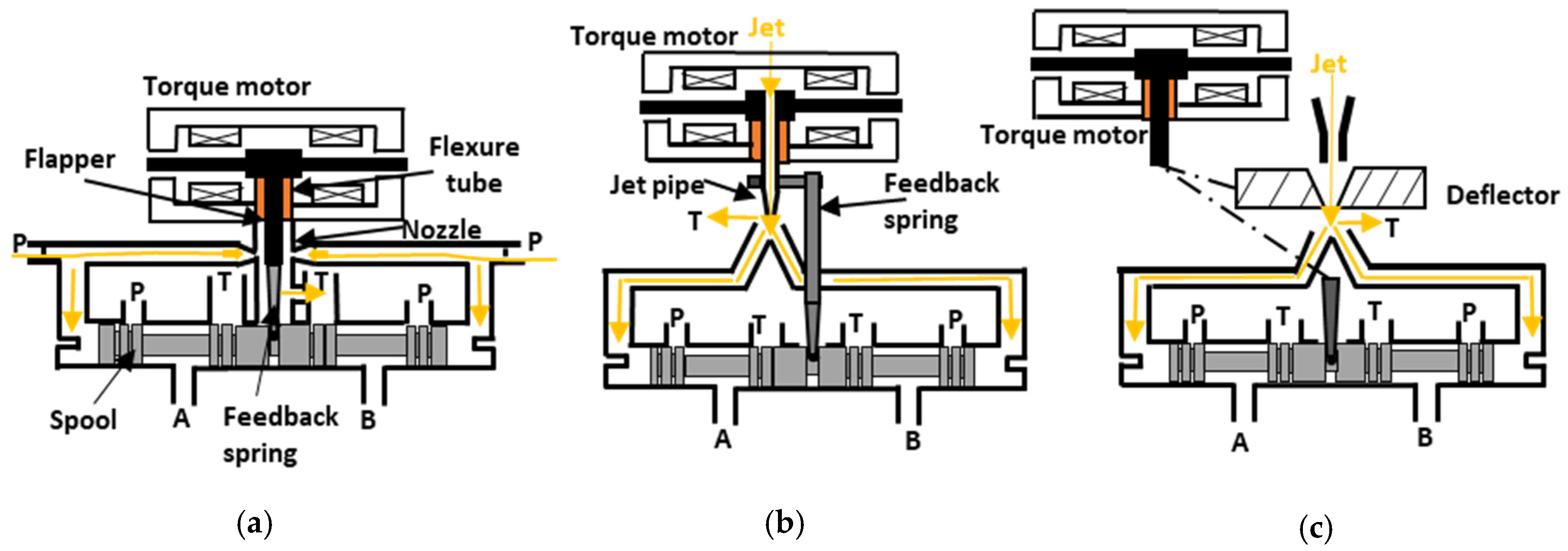
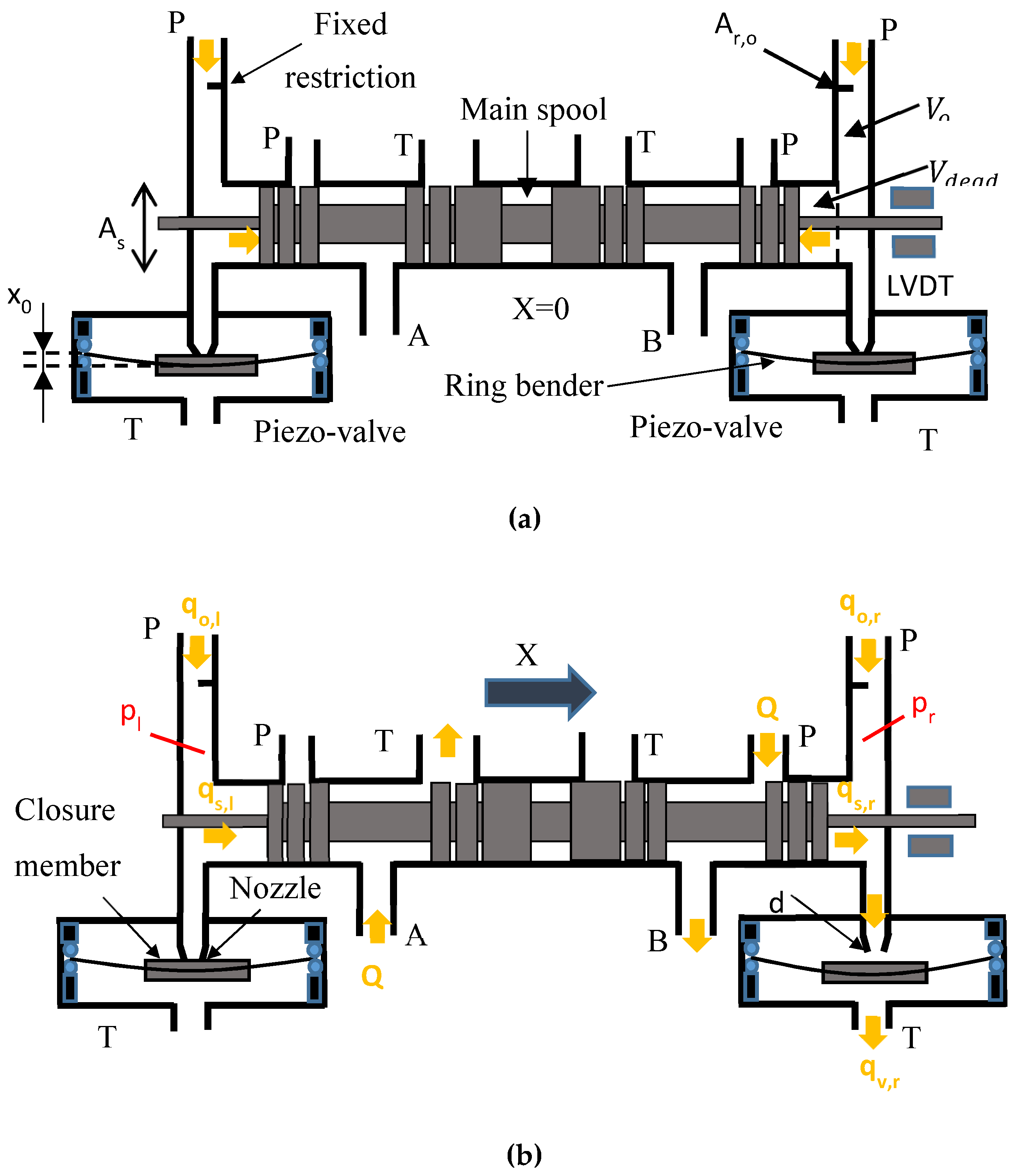
2. Novel Servovalve Architecture

The proposed architecture uses piezoelectric actuators, which are elements capable of deforming when a voltage is applied to them, thus transforming an input voltage into displacement and, hence, into actuation force. There are four main types of piezoelectric actuators that are available on the market: piezo-stacks, amplified piezo-stacks, rectangular benders, and ring benders [25]. As explained in Section 1, according to previous studies, the most suitable piezoelectric actuator for the actuation of the pilot stage of servovalves seems to be the ring bender because it can provide sufficiently large actuation forces and good levels of displacement that are compatible with these applications, while being very compact, unlike piezo-stacks and amplified stacks, which are too bulky to be implemented into two-stage servovalves.
A picture of a ring bender is provided in Figure 2a; it is an annular disc that deforms when a voltage from an amplifier Vamp (comprised between −Vmax and +Vmax) is applied to it. Positive values of the voltage allow the ring bender to move in a direction, whereas negative values enable the movement in the opposite direction. Figure 2b shows the force–displacement relationship of a ring bender as a function of the applied voltage ranging from 0 to +Vmax (a similar graph is valid for −VmaxVamp ≤ 0). Like all piezo-actuators, the ring bender behaves like a spring of stiffness krb to which a force Fb (called blocking force) is applied. This actuation force, which is proportional to the applied voltage, is gradually reduced when the ring bender moves from its neutral position because of its stiffness. Therefore, for a given voltage, a linear relationship exists between displacement and force, and the slope of this straight line depends on the stiffness of the ring bender. The stiffer the ring bender, the more horizontal this line becomes in the force–displacement plane. An increase or decrease in the voltage (from 0 to +Vmax or vice versa) causes the straight line to translate along the force–displacement plane until the minimum voltage or the maximum voltage is reached.
The displacement obtained for the voltage set to its maximum value ( + V m a x ) and for a null actuation force is also referred to as the maximum free stroke of the ring bender ( L m a x ). Similarly, the actuation force obtained when the voltage is the maximum ( + V m a x ) and when the ring bender is blocked in its neutral position is called the maximum blocking force of the ring bender ( F b , m a x ). The stiffness of the ring bender k r b can be calculated as the ratio of F b , m a x and L m a x .
The characteristics of commercially available ring benders are reported in Table 1, showing that different levels of force, displacement, and stiffness are available [25]. A method of correctly selecting a ring bender is proposed in the following sections.
A scheme of the proposed architecture employing ring benders is shown in Figure 3; it is composed of two small two-way two-position (2/2) piezo-valves (i.e., valves actuated by piezoelectric ring benders), which are tasked with changing the pressure at the extremities of a main spool of a typical four-way valve. The differential pressure, which allows the spool to move from its neutral position (null), is produced by opening and closing the piezo-valves, which are both hydraulically connected with the main stage and with two fixed orifices, which are, in turn, hydraulically connected with the high pressure port P. The closed loop control is implemented by a linear variable differential transformer (LVDT). The closure member can be inserted through the hole of the ring bender using o-ring elastomers; similarly, the ring bender can be attached to the valve body using o-rings. The o-rings are fundamental for ensuring the mechanical integrity of the ring bender while deforming inside the valve.
The main advantage of the proposed architecture compared to those shown in Figure 1 is that the internal leakage through the two piezo valves is negligible when the main spool is at rest in the neutral position. This feature significantly reduces the overall internal leakage compared to typical two-stage servovalves, whose pilot stages always require a quiescent flow to operate, even when the main spool is at rest in the neutral position (null). Therefore, in commercial two-stage servovalves, the overall leakage at null is given by the sum of the leakage in the main stage and the leakage in the pilot stage; instead, in the proposed configuration the leakage at null is only due to the leakage in the main stage.
In addition, the torque motor is removed, along with its associated disadvantages, such as the high number of parts, complexity, and noise sensitivity.
The proposed architecture was preliminarily studied in [26], in which a simulation model was developed to predict the performance of this architecture for a medium size valve, showing that the response time can be very short, with an interval time of about 7 ms being predicted to change the main spool position from 0% to 90% of the maximum opening (X = 1 mm). That simulation work assumed some estimated values for the damping factor of the ring bender and for the amplifier parameters, which were taken from other studies [21].
The preliminary results of [26], being promising, encouraged us to construct a piezo-valve prototype, which was tested in a test rig, reproducing only the pilot stage of the architecture shown in Figure 2, including the fixed restriction Ar,0 and the chamber of volume V0 between the fixed restriction and the piezo-valve [27]. This research activity was described thoroughly in [27], which must be regarded as the first part of the present study. The valve prototype and the test rig, which, for simplicity, were constructed with non-optimized parameters (for example, the volume V0 and the mass m0 of the moving parts were quite large), were instrumental in validating a numerical model for the pilot stage [27]. The damping factor of the ring bender, the amplifier parameters, and the hysteresis parameters were evaluated with good accuracy in [27], thus obtaining more precise values compared to the previous study [26]. Despite using large values for V0, m0, and for the maximum opening of the ring bender (xmax), the experimental results confirmed that the piezo-valve has high potential in terms of step response speed, since the interval time required for the displacement of the ring bender to change from 0% to 90% of its final value considered in the tests (xmax = 0.15 mm) was less than 5 ms [27]. The pilot pressure remained constant when the valve was kept closed, thus proving that the quiescent flow through the piezo-valve is negligible compared to commercial pilot stages [27]. The numerical analysis performed in [27] showed that the reduction of V0 and m0 can be instrumental in further improving the performance of the pilot stage in terms of response speed.
The present paper is the second part of the previous work [27]. The pilot-stage model, tuned and validated in [27], is here coupled with a well-established main stage model to provide an accurate simulation of the entire valve concept (pilot stage + main stage). A general design procedure, based on simplified equations, is now developed, allowing the effective selection of the values of the geometrical parameters of the pilot stage for a given main stage spool. Some of the geometrical parameters of the pilot stage, here used, have different values from those employed in the prototype (whose geometrical parameters were not optimized), including lower values for V0, m0, and xmax.
The obtained valve configuration is assessed in terms of response speed using the full numerical model. The aim is to achieve more accurate performance predictions than [26], since now more precise values for the damping factor of the ring bender, for the amplifier parameters, and for the hysteresis parameters are used in the simulations, taking advantage of the more recent study [27]. The full numerical model and the simplified model are described in the following sections.

3. Full Numerical Model

The transient behavior of the novel servovalve architecture is studied in this paper using a detailed numerical model composed of two parts: the main stage model and the pilot stage model. The main stage model uses well-established equations, and all the parameters that need to be defined in these well-established equations (e.g., the damping factor, mass, and geometry of the main spool) can be taken from the literature and do not need any experimental validation. Instead, the pilot stage model needs some parameters to be tuned experimentally, such as the damping factor of the ring bender, the natural frequency and damping factor of the amplifier, and the coefficients of the hysteresis equations. The tuning of these parameters, along with the experimental validation of the pilot stage model, was achieved in the first part of the present study [27].

3.1. Main Stage Model

With reference to Figure 3b, assuming that the spool moves from the left (l) to the right (r), the equilibrium of the forces acting on the spool can be written as:
( p l p r ) A s F f , s C X ˙ M X ¨ = 0   ,
where ( p l p r ) A s is the actuation force generated by the differential pressure ( p l p r ) acting on the lateral surfaces of area A s = π D s 2 4 ; D s denotes the diameter of the main spool; F f , s is the flow force that opposes the actuation force; C X ˙   and M X ¨ are the damping force (accounting for friction) and the inertia force, respectively; and C and M indicating the damping factor and the mass of the main spool, respectively.
The flow force is calculated using the following equation [22,24,26]:
F f , s = 2 ρ 0 Q 2 A r , s c o s θ   ,  
where the factor 2 is due to two metering chambers being opened simultaneously (P-A and B-T, for a left displacement of the spool, or P-B and A-T, for a right displacement of the spool), ρ 0 is the oil density at the atmospheric pressure p 0 , Q is the volumetric flow rate computed with reference to ρ 0 , A r , s is the restriction area through each metering chamber, and θ is the velocity angle with respect to the horizontal direction at section A r , s [24]. The value of the restriction area is determined as follows:
A r , s = b X   if   X > 0   ,  
A r , s   = A l , s = b c   if   X = 0   ,
where b is the overall slot width, A l , s is the spool leakage area, and c is the clearance [28,29,30]. The effects of fluid erosion and geometrical imperfections, which could increase the leakage area as shown in [28,31,32], is neglected in this analysis.
The flow rate through each metering section of the main stage is calculated using the orifice equation [30]:
Q = C D A r , s 2 Δ p ρ 0   ,  
where C D is the discharge coefficient and Δ p is the pressure drop across the restriction area A r , s . In the model, ports A and B are hydraulically connected and the pressure drop p B p A is neglected. Therefore, the pressure drop in Equation (5) becomes: Δ p = p A p T = p P p B = ( p P p T ) / 2 .
The flow rates qs,l and qs,r flowing inside the external chambers of the main spool are calculated as follows:
q s = d ( ρ ρ 0 V ) d t = d ( ρ ρ 0 ) d t V ± ρ ρ 0 X ˙ A s   ,
where, in the case of the spool moving from the left to the right (Figure 3b), the sign + must be used for the calculation of qs,l and the sign – must be used for qs,r, (the opposite occurs when the spool moves from the right to the left). Equation (6) also allows the compressibility effects to be considered, with ρ denoting the actual density of the oil and V denoting the volume at the left or right of the main spool, calculated as follows:
V = V d e a d ± X A s   ,
where V d e a d is the dead volume when the spool is in the central position (Figure 3a), which can be taken as equal to: V d e a d =   X m a x A s . With reference to the mail spool moving from the left to the right (Figure 3b), the sign + must be used for the left chamber and the sign – for the right chamber (the opposite is true for the spool moving from the right to the left). The actual density of the oil ρ is calculated as follows [22,24,26]:
ρ = ρ 0 ε 1 ε ( p 0 p p 0 ) 1 γ + e p p 0 E 0   ,
where ε accounts for the quantity of air present in the oil, E0 is the bulk modulus at atmospheric pressure, p   is the absolute pressure, and γ is the ratio of the specific heats of the gas.

3.2. Pilot Stage Model

Two equations for the conservation of the flow rate must be satisfied: one for the left part of the pilot stage and the other one for the right part. Again, with reference to the spool moving from the left to the right (Figure 3), the two equations are:
q o , l = q s , l + q c , l + q v , l   ,
q v , r = q o , r + q s , r q c , r   ,
where q o is the flow rate across the fixed restriction having area A r , 0 , q v is the flow rate entering and exiting the piezo-valve, and q c is the flow rate entering, due to the oil compressibility, the chamber having volume V 0 and connecting the fixed restriction with the nozzle of the piezo-valve; subscripts l and r indicate the left and the right part of the pilot stage, respectively.
The flow rate through the fixed restriction is calculated using the orifice equation [30], and imposing A r   = A r , 0   (restriction area of the fixed orifices), thus obtaining:
q 0 = C D A r , 0 2 Δ p ρ 0   ,  
where Δ p   = p P p l to calculate q 0 , l and Δ p   = p P p r to calculate q 0 , r .
The flow rate q c   entering the chamber of volume V 0 due to the oil compressibility (Figure 3a) is computed using the following equation [24,26,27]:
q c = V o E d ( p p 0 ) d t   ,
where p must be taken as either equal to p l to calculate q c , l   or equal to p r to calculate q c , r . The bulk modulus E, as a function of the pressure (p), is [24,26,27]:
E = E o 1 + ε ( p 0 p ) 1 / γ 1 + ε p 0 1 / γ γ   p ( γ + 1 ) / γ   E o   .  
The flow rate through each piezo-valve is computed by the orifice equation [30]:
q v = C D A r , v 2 Δ p ρ 0     ,
where Δ p   = p l p T is used to calculate q v , l and Δ p = p r p T to calculate q v , r . The orifice area in Equation (14) is evaluated as follows:
A r , v = π d x   i f   x > 0   ,  
A r , v = A l , v = π d r   i f   x = 0   ,
where d is the diameter of the nozzle of the piezo-valve and x is the displacement of the ring bender with respect to the nozzle tip. The leakage area of the piezo-valve A l , v   is calculated as the product of the nozzle perimeter π d and the roughness r.
The equilibrium of the forces acting on the ring bender leads to the following equation [24,26,27]:
F b + F f , r b m 0 x ¨ C r b x ˙ k r b ( x + x 0 ) = 0   ,  
where F b denotes the blocking force, F f , r b is the flow force acting on the ring bender, C r b   is the damping factor of the ring bender, m0 is the mass of the moving parts (ring bender, o-rings, and closure member), k r b is the stiffness of the ring bender, x is the displacement of the ring bender measured from the nozzle tip, and   x 0 is the pre-compression of the ring bender. The flow force acting on the ring bender is computed using the following simplified equation [26,27,30]:
F f , r b = Δ p Π d 2 4   ,  
where   Δ p = p l p T for the left piezo-valve and Δ p = p r p T for the right piezo-valve.
The ring bender displacement is limited by two mechanical stops (an upper bound x m a x and a lower bound x m i n ), each simulated by a spring (having a stiffness K s t o p ) combined with a damper (having a damping coefficient   C s t o p ). When the lower and upper bounds are reached, a force Fstop acts to stop the ring bender, computed as follows [24]:
F s t o p = K s t o p ( x m a x x ) + C s t o p d d t ( x m a x x )   for x x m a x     ,
F s t o p = K s t o p ( x m i n x ) + C s t o p d d t ( x m i n x )   for x x m i n   .
Each ring bender needs an amplifier having the task of transforming an input control voltage Vc (comprised between −5 and +5 V) into a high output voltage V a m p (between −100 and +100 V). The relation between the output and the input voltage is simulated using a second-order transfer function H ( s ) [21]:
H ( s ) = K a ω n 2 s 2 + 2 ξ ω n s + ω n 2   ,
where s is the complex variable; K a , ω n , and ξ   are the gain, natural frequency, and damping factor of the amplifier, respectively. The current limit of the amplifier I m a x is computed as follows:
d V a m p d t = I m a x C a p   ,
where Cap is the capacitance. The output voltage applied to the ring bender is transformed into a blocking force:
F b = K d , v ( V a m p n ) ,
where Kd,v is the conversion factor (from voltage to force) and n is a factor accounting for piezo-electric hysteresis. This factor is evaluated using the Bouc–Wen hysteresis equation [21]:
d n d t = α d v d V a m p d t β | d V a m p d t | n δ d V a m p d t | n |   ,
where α, d v , β, and δ are unknown coefficients.
The value of the control voltage Vc (−5 V ≤ Vc ≤ +5 V) is determined using a proportional-integral-derivative (PID) controller with a parallel form:
V c , l = K p e ( t ) + K I 0 t e ( τ ) d τ + K D d e ( t ) d t   for   e ( t ) 0   ,
V c , r = [ K p e ( t ) + K I 0 t e ( τ ) d τ + K D d e ( t ) d t ]   for   e ( t ) 0 ,
where e(t) is the error between the actual spool position and the demand, with K p , K i , and K D   being the proportional, integral and derivative gains, respectively.

4. Simplified Numerical Model

Some of the equations described in the previous section are here simplified and combined to obtain a simplified model that can easily be employed to choose the values of the main parameters of the pilot stage for a given geometry of the main stage.
The main parameters of the pilot stage are: the area of the fixed orifice A r , 0 , the diameter of the nozzle of the piezo-valve d, the maximum opening of the piezo-valve xmax, and the maximum free stroke L m a x and maximum blocking force F b , m a x that the ring bender must provide. Once L m a x and F b , m a x   are determined, the ring bender can be selected among the commercially available models.
These parameters ( A r , 0 , d, xmax , L m a x , and   F b , m a x ) must be calculated with reference to a given main spool, which must be able to provide the desired maximum flow rate ( Q m a x ) at the maximum opening ( X m a x ) for a reference supply pressure ( p P ). Thus, the values of the lateral area A s and slot width b are known in this calculation. In addition, the spool must reach a maximum velocity ( v m a x ) to ensure the desired response speed of the valve. According to the real behavior of a spool valve, this maximum velocity is obtained at about one half of the spool stroke when the spool is moving to reach the maximum opening ( X m a x ) . When approaching the maximum opening, the spool velocity is reduced by the control system to avoid overshoots. Therefore, it can be assumed that the main spool has a constant velocity v m a x in correspondence with X m a x / 2 , and that, under these conditions, the inertia force can be neglected. The effects of the fluid compressibility and the leakage areas can be neglected at this design stage as well. With these assumptions, some of the previous equations can be combined using X   = X m a x /2, and X ˙   =   v m a x . As a result, for the spool moving from the left to the right, the combination of Equations (1), (2), (3), and (5) leads to:
( p l p r ) A s C D 2 b X m a x ( p P p T ) c o s θ C v m a x = 0   .
Combining Equations (6), (9), and (11), and neglecting the fluid compressibility and the leakage flow lead to:
C D A r , 0 2 ( p P p l ) ρ 0   = v m a x   A s   .
Finally, the combination of Equations (6), (10), (11), (14) and (15), applying x = xmax (condition needed to reach X ˙   = v m a x   ) , leads to:
v m a x   A s + C D A r , 0 2 ( p P p r ) ρ 0   = C D π d x m a x 2 ( p r p T ) ρ 0   .  
Equations (27) to (29) allow   x m a x , p l , and p r to be computed as a function of d and A r , 0 for given values of X m a x , v m a x , b,   A s , p P , and p T .
At the design stage, the leakage through the piezo-valve must be evaluated when the ring bender fully opens the valve. In this regard, either the left-hand side or the right-hand side of Equation (29) can be used to evaluate the maximum flow rate through the piezo-valve. For example, using the left- hand side of Equation (29), we obtain:
( q v , r ) max   = v m a x   A s + C D A r , 0 2 ( p P p r ) ρ 0   .
The calculated values must be compatible with the characteristics of the ring bender. Specifically, the maximum displacement x m a x added to the pre-compression of the ring bender x 0 must be less than or equal to the maximum free stroke L m a x that the chosen ring bender can provide. In addition, to ensure that the piezo-valve can be closed, the maximum blocking force provided by the ring bender plus the pre-compression force must be greater than or equal to the flow force when the piezo-valve is closed (namely, F f , r b ( x = 0 ) = Π d 2 4 ( p p p T ) ). Finally, the restriction area of the piezo-valve ( π d x m a x ) must be lower than the nozzle area of the piezo-valve ( π d 2 4 ) to allow flow modulation by acting on the displacement of the ring bender. Therefore, the following inequalities must be satisfied:
x m a x + x 0 L m a x   ,
Π d 2 4 ( p p p T ) F b , m a x + k r b x 0   ,
π d x m a x < π d 2 4   .  
For the pre-compression x 0 to be given to the ring bender, its value can be equal to or greater than zero. In some cases, the value of x 0 can be computed so that the ring bender can close the piezo-valve even when there is no voltage applied to the ring bender (for example, in the case of a malfunctioning electric system). This is particularly important for aircraft applications, where an uncontrolled movement of the actuator must be avoided for safety reasons. Therefore, the pre-compression of the ring bender x 0 can be calculated by applying F b , m a x = 0   in relation (32), and assuming a correction factor of 1.2 to account for hysteresis, thus obtaining:
1.2 Π d 2 4 k r b ( p p p T ) = x 0   .

5. Results

In this final section, the simplified model is employed to choose the values of the geometrical parameters of the pilot stage for a given medium size main spool. Afterward, the transient behavior of the obtained valve configuration is predicted using the full model implemented in SimScape Fluids software.

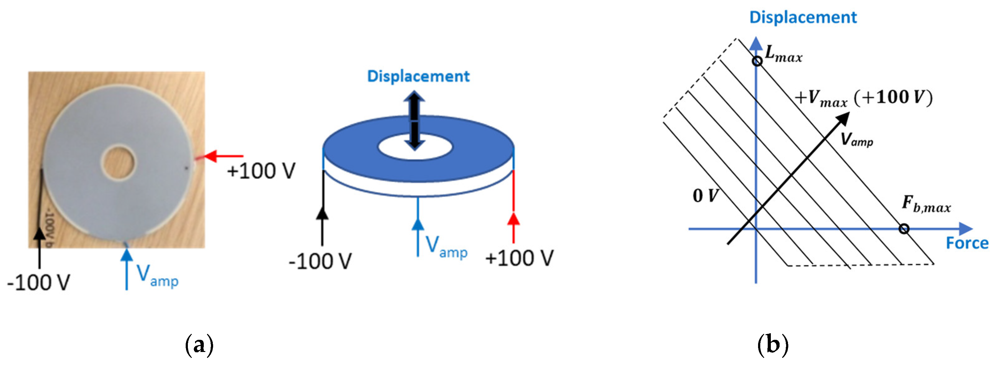
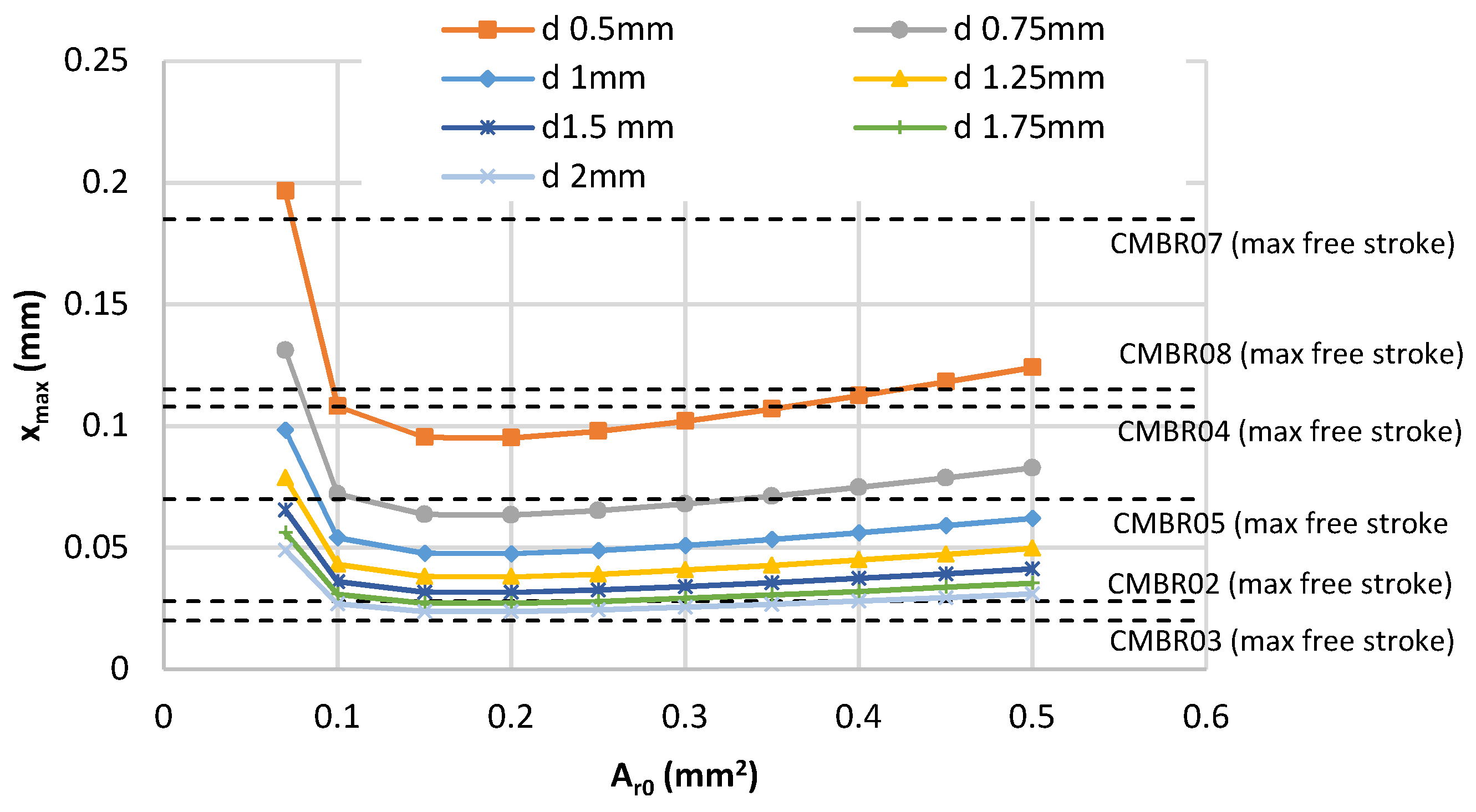
5.1. Choice of the Values of the Design Parameters

The simplified numerical model described earlier is now employed to choose the values of the main geometrical parameters of the pilot stage. In this analysis, a spool suitable for a medium size valve is considered, having the following geometrical parameters: main spool diameter D s = 7 mm, spool lateral surface A s = 38.5 mm2 , maximum spool displacement X m a x = 1   mm, and slot width b = 10 mm (this spool is the same as that used in [26]). A maximum spool velocity v m a x = 0.25 m/s is assumed to have a very fast valve, with a response time comparable with current commercial units [33]. In addition, a supply pressure of p P   = 210 bar is considered, which is a commonly used value to assess the performance of commercially available servovalves used for aircraft [26,33]. The discharge pressure is assumed to be p T = 1 bar. The density of the hydraulic oil is assumed to be ρ 0 = 851 kg/m3 (corresponding to the density of oil ISO VG 32 at 50 ° C). With these operating parameters, the maximum flow rate through the main stage is Q m a x = 65.8 L/min, which is a typical value for a medium-sized valve (obtained through Equation (5), with CD = 0.7).
Using Equations (27) to (29), we determined the maximum displacement from the nozzle tip ( x m a x ) that the ring bender must ensure as a function of the area of the fixed orifice A r , 0 and of the diameter of the piezo-valve nozzle d. The discharge coefficient CD and the flow angle θ   are assumed to be 0.7 and 69° [30], respectively, under the assumption of turbulent flow.
The graph in Figure 4 shows that for a given value of the restriction area of the fixed orifice A r , 0 , the reduction in the nozzle of the piezo-valve d causes a corresponding increase in the maximum displacement of the ring bender x m a x . Notably, x m a x is also strongly affected by the restriction area of the fixed nozzles A r , 0 . For a given value of d, the curves present a minimum corresponding to A r , 0   = 0.15 mm2.
In Figure 4, the maximum free stroke L m a x of the commercially available ring benders is also plotted with dashed lines, showing that, of the six ring benders considered, model CMBR03 provides too low values of L m a x , regardless of d and A r , 0 ; therefore, inequality (31) cannot be fulfilled using this model.
The minimum value considered for the nozzle diameter of the piezo-valve is d = 0.5 mm; lower values were not considered because, as shown in Figure 5, the ratio of the nozzle area of the piezo-valve π d 2 / 4 and the restriction area of the piezo-valve π d x m a x becomes too close to unity at d = 0.5 mm. Therefore, for d < 0.5 mm, relation (33) is not fulfilled, and it is not possible to obtain a suitable flow rate modulation by acting on the ring bender displacement.
Figure 4 and Figure 5 indicate that choosing a large diameter d for the nozzle of the piezo-valve allows x m a x to be reduced, thus providing a wide choice for the selection of the ring bender; however, as shown in Figure 6, the flow force at x = 0 increases with increasing nozzle diameter d. Therefore, for large values of d, the selected ring bender would not be capable of providing a blocking force sufficiently high to close the piezo-valve, although pre-compression can be adopted to increase the closure force (see inequality in Equation (32)). In Figure 6, the maximum blocking force F b , m a x of commercially available ring benders is also plotted using dashed lines, showing that for d > 1.5 mm, the flow force becomes higher than the maximum blocking force of commercially available ring benders.
Another factor that must be considered during the design of the pilot stage is the leakage through the piezo-valve when the ring bender fully opens the piezo-valve. To this end, Equation (30) can be used, which shows that, having chosen the values for v m a x and A s   , the maximum leakage flow rate ( q v , r )max depends only on the value of A r , 0 (since pr is a function of A r , 0 only). Figure 7 depicts the maximum leakage flow rate ( q v , r )max versus A r , 0 ; this graph shows that choosing small values for A r , 0 reduces the leakage and hence the power consumption when the piezo-valve is fully open.
Further relevant elements that can be considered during the design stage are represented by the values of the pressure at the left and right of the main spool, pl and pr, when X ˙ = v m a x . According to Equations (27) to (29), these values depend only on the area of the fixed orifices A r , 0 once the operating parameters of the main stage are defined (i.e., maximum flow rate, velocity, and main spool geometry). Figure 8 shows the trends in pl and pr as a function of A r , 0 . This behavior is consistent with the distribution of xmax provided in Figure 4; for values lower than A r , 0   = 0.15 mm2 , both pl and pr experience a considerable drop, which results in pl and pr being less than zero for A r , 0 < 0.07 mm2 (unreal operating condition).
The analysis of both Figure 7 and Figure 8 leads to the conclusion that a value of A r , 0 = 0.1 mm2 is a good choice for achieving low values of ( q v , r )max while guaranteeing sufficiently high values of pl and pr . Concerning d, the choice of d = 1 mm can ensure the good regulation of the piezo-valve (Figure 5) and moderate values for the maximum opening and for the flow force at x = 0, as shown in Figure 4 and Figure 6, namely x m a x = 0.05406 mm and F f , r b ( x = 0 )   = 16.4 N. For these operating conditions, model CMBR08 is selected because it can satisfy the relations in Equations (31) and (32), having L m a x   = 0.115 mm and F b ,   m a x   = 39 N, and due to its high stiffness ( k r b = 0.34 N/µm). Due to the high stiffness, a pre-compression x 0 can be assigned to model CMBR08 to close the piezo-valve even when there is no voltage applied to the ring bender. Equation (34) allows x 0 to be computed, leading to x 0 = 0.05793 mm.
Table 2 and Table 3 respectively summarize the input and the output parameters of the proposed design procedure. The value chosen for the diameter of the nozzle d is the same as that employed in the test rig in [27]. Concerning the ring bender, instead of model CMBR08 (selected in this paper), model CMBR07 (having lower actuation forces but similar dimensions) was used in the test rig in [27] because lower actuation forces were needed in the tests, being performed with lower supply pressures (up to 70 bar).

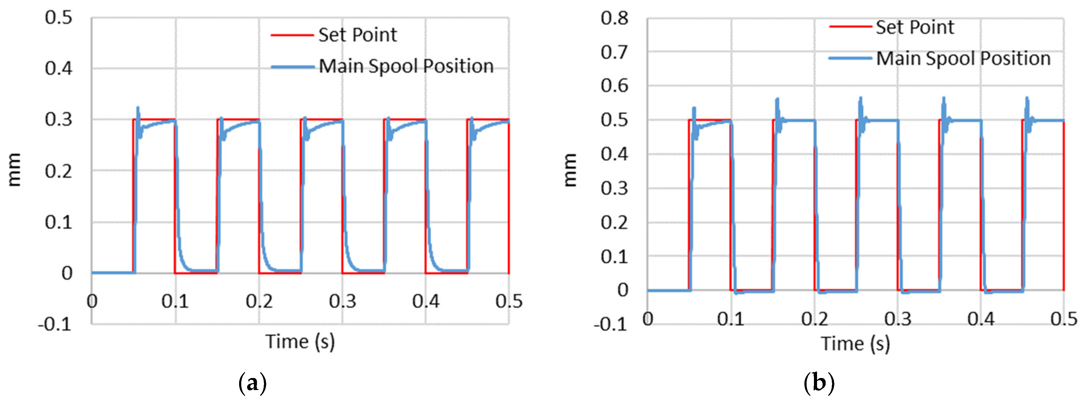
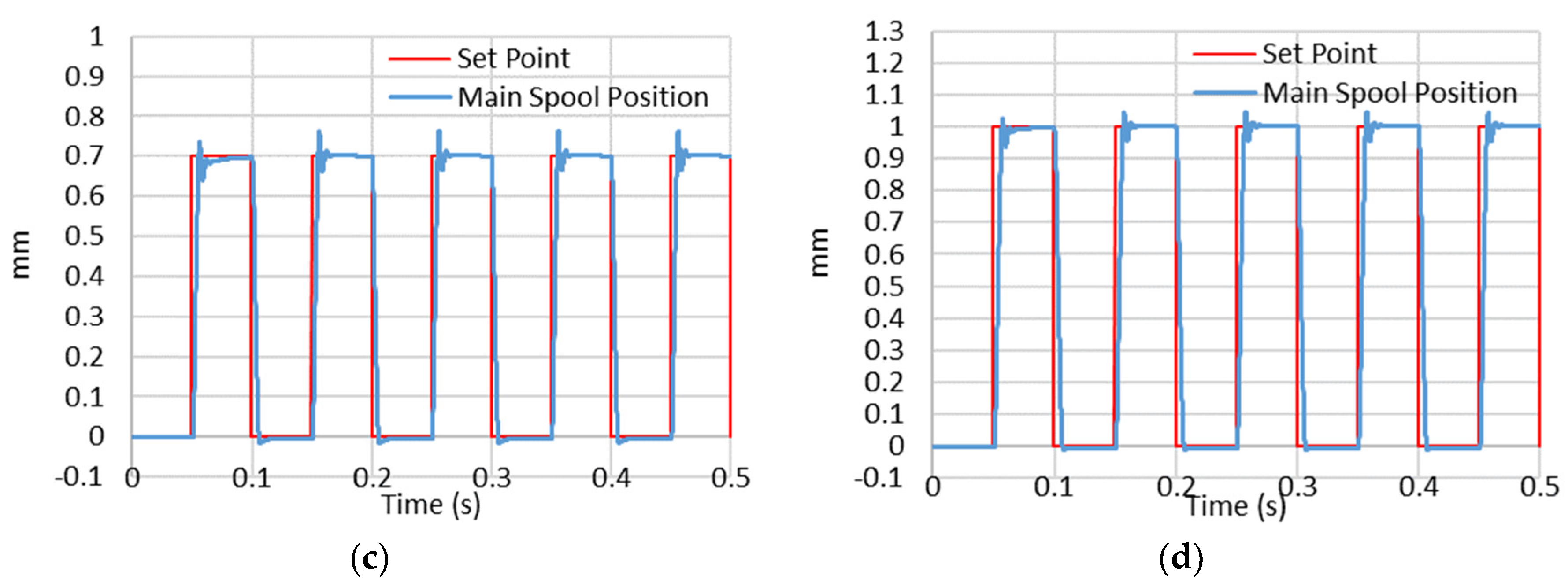
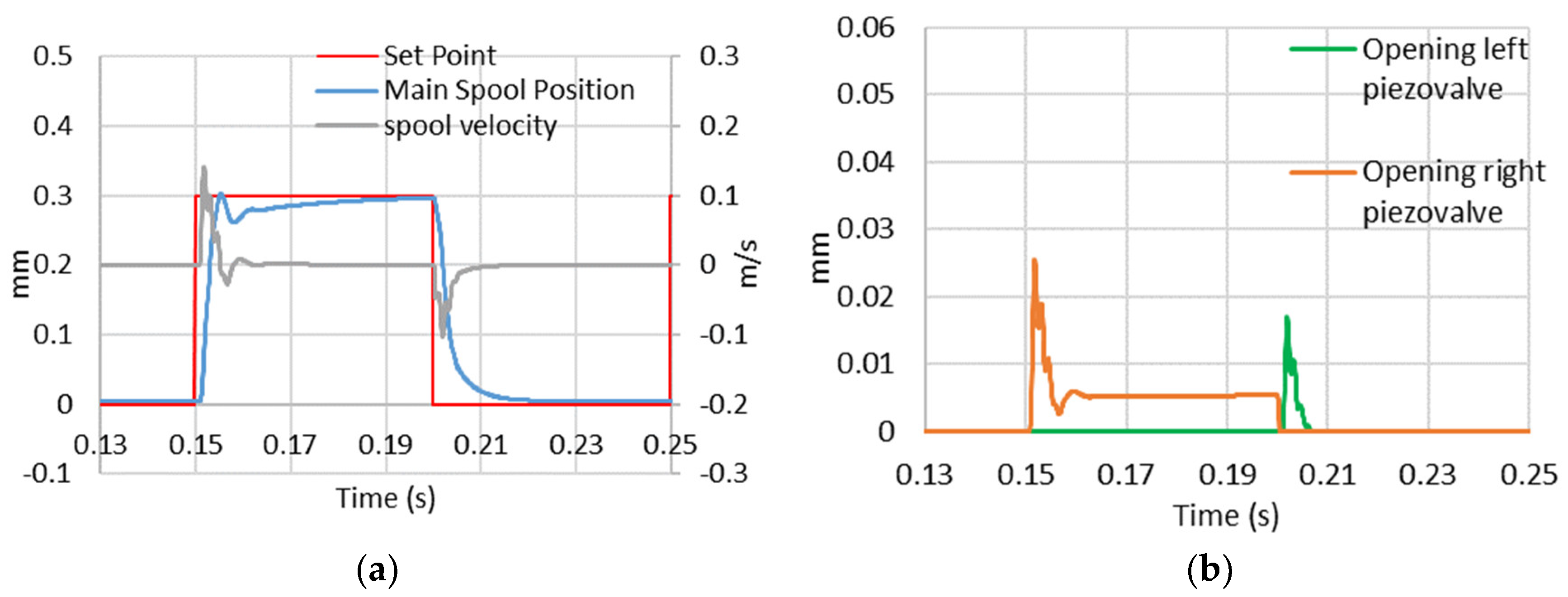
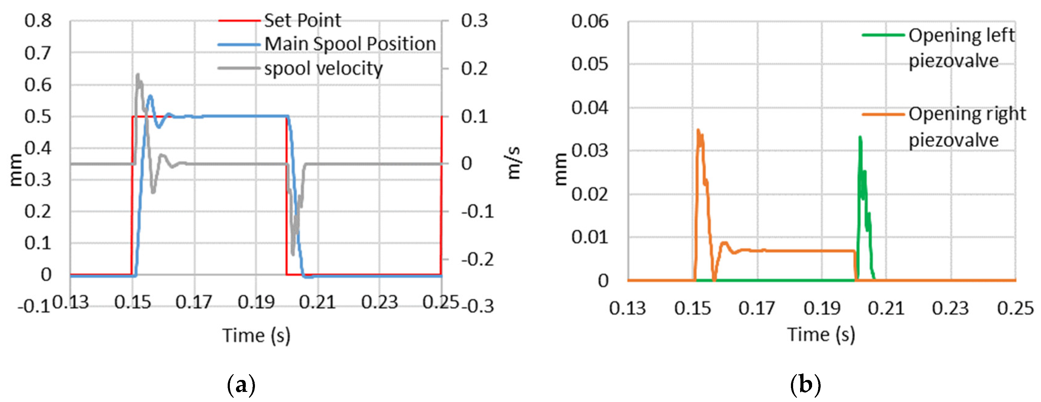
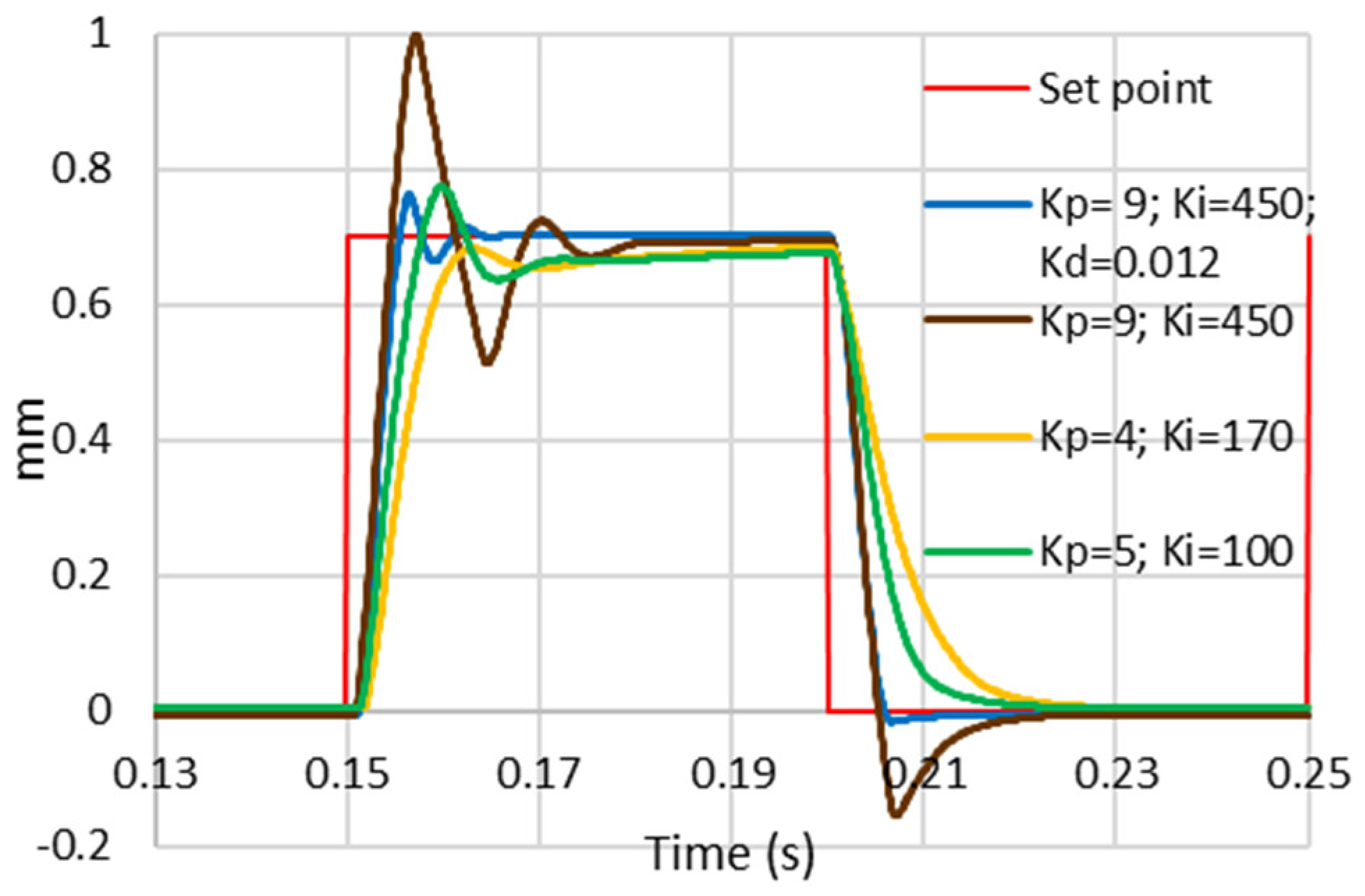
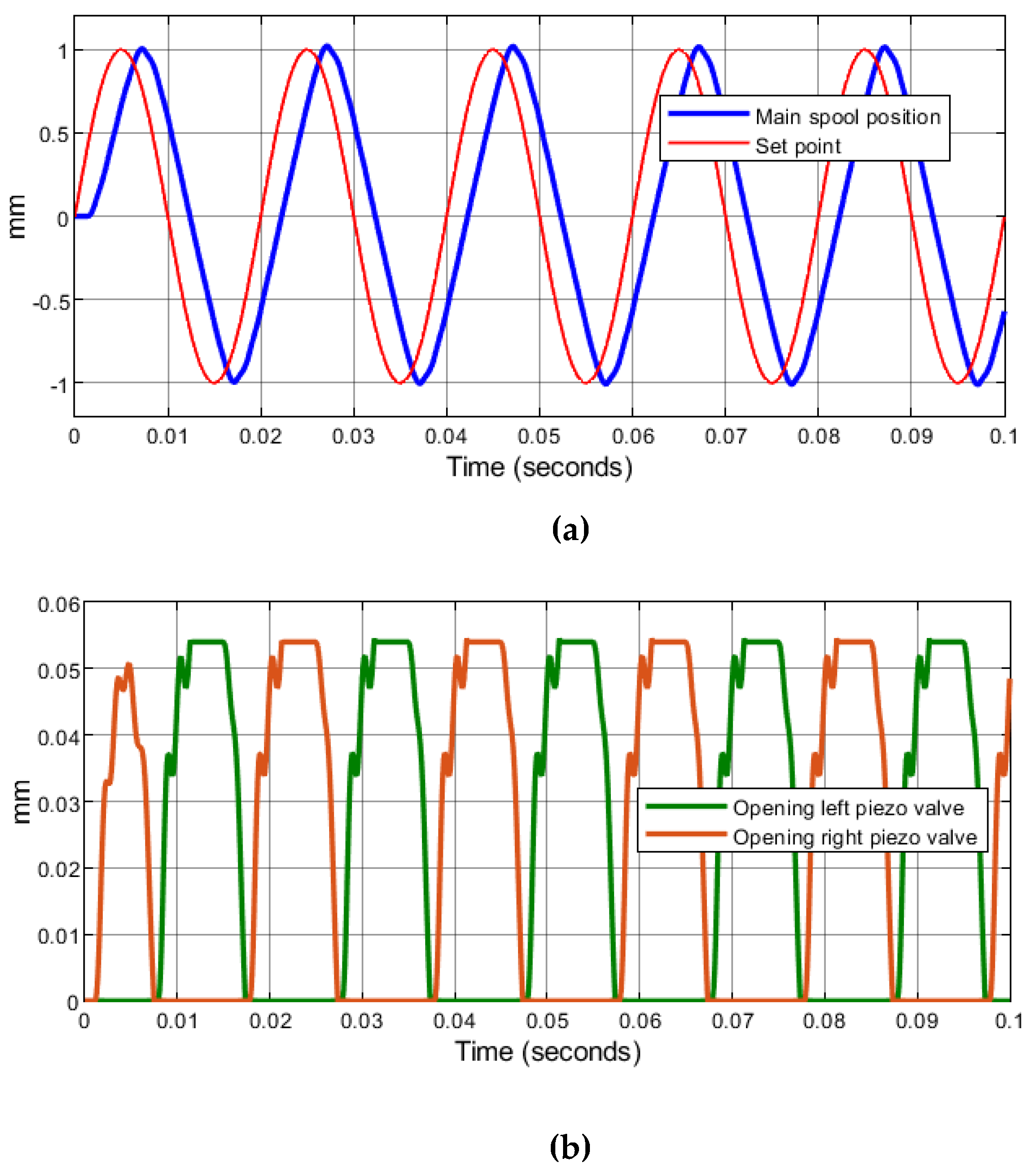
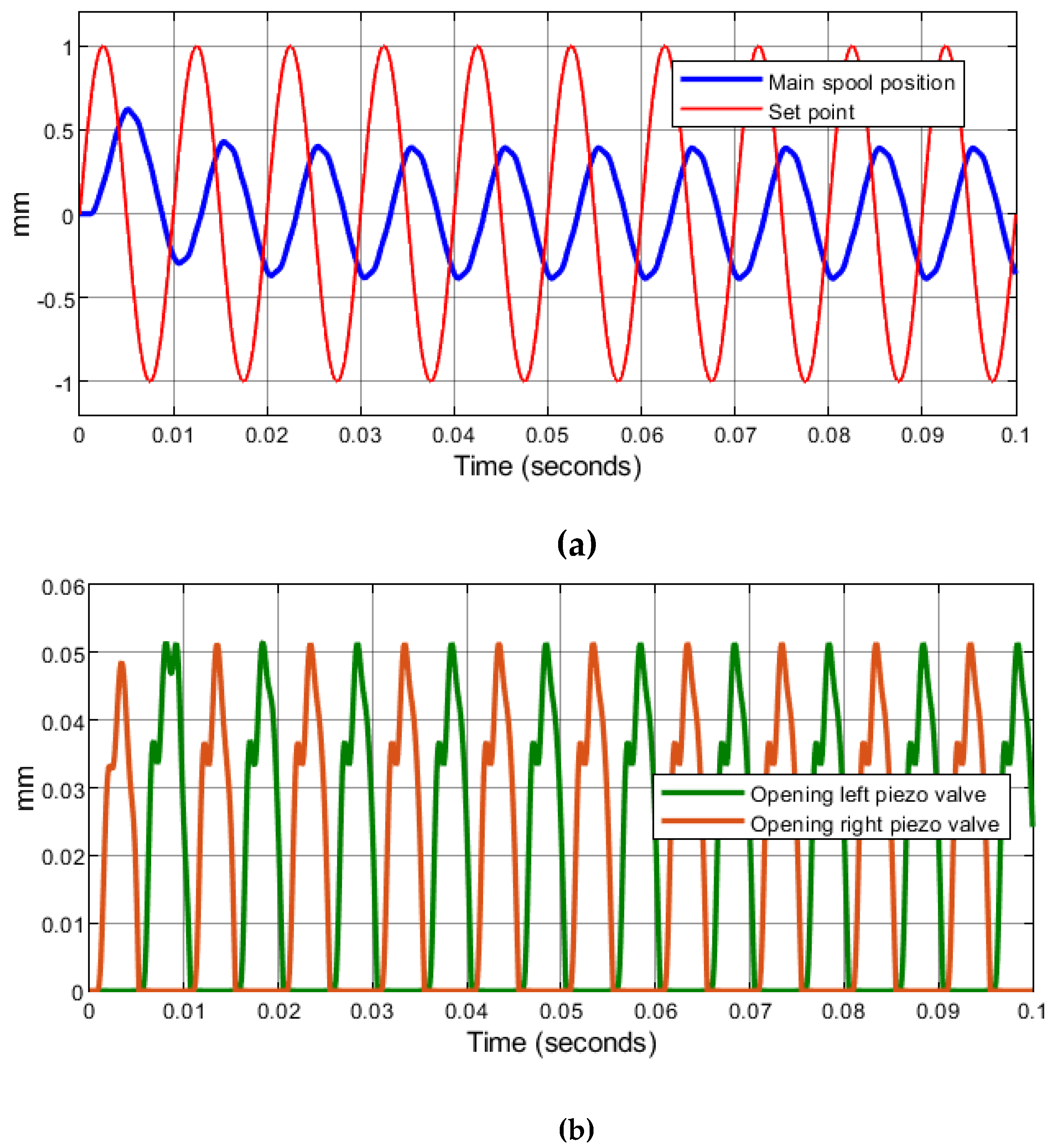
5.2. Performance Prediction

The design procedure employed in the previous subsection provided the values of the main geometrical parameters of the pilot stage and of the ring bender for a given spool typical of a medium size valve.
In this section, the performance of the obtained valve configuration is discussed. Such performance was predicted by simulating four step response tests and two sine wave tests using the model equations provided in Section 3, implemented into the SimScape Fluids framework [24]. The system of equations was solved using the fixed step solver Ode14x with a time step of 10−4 s [24].
The simulation of the transient behavior requires the knowledge of the damping factor C r b and mass m0 of the moving parts (ring bender plus closure member plus elastomers). The experimental analysis performed in [27] estimated a damping factor C r b = 26 N/(m/s) for the piezo-valve assembly realized in that study. In addition, the authors assessed that it is important to reduce the mass of the moving parts of the piezo-valve as much as possible to improve the response speed of the ring bender. Considering that the weight of the ring bender is only 6 g, the moving parts can easily be realized to obtain an overall mass of the order of m0 = 20 g.
With regard to the leakage area of the piezo-valve, Equation (16) leads to A l , v   = 3.14159 10−9 m2 applying d = 1 mm (previously determined) and r = 1 μm, which is a value of roughness achievable through an abrasive machining process. The simulation of the interaction between the moving parts and the mechanical stops requires the values of K s t o p and C s t o p to be given (see Equations (19) and (20)); these parameters were estimated in [27] as K s t o p = 108 N/m and C s t o p   = 500 N/(m/s).
This performance prediction also requires the knowledge of the oil volume V 0 (see Figure 3). The analysis performed in [27] showed that this volume must be reduced as much as possible to ensure the pilot pressures ( p r and p l ) respond very quickly. This volume can be taken as equal to that of a cylinder having a height L 0 and a diameter D 0 . The values used in [26] are here employed: L 0   = 40 mm and D 0 = 3 mm.
Concerning the main spool, the values of the mass and damping factor are equal to those used in [26]: M   = 20 g and C   = 10 N/(m/s). Using Equation (4), applying b = 10 mm and c = 3 μm (a value typical of servovalves [28]), the leakage area of the main spool is A l , s = 3 10−8 m2. The dead volume V d e a d (see Equation (7)) is 38.5 mm3 for X m a x = 1 mm and A s = 38.5 mm2.
As far as the parameters of the amplifier are concerned, the natural frequency and damping factor of the amplifier produced by the manufacturer NOLIAC [25] for the CMBR08 ring bender (having gain K a = 20 )   were retrieved in [27], obtaining ω n = 1400 rad/s and ξ   = 1.5. The conversion factor of the CMBR08 ring bender as provided by the manufacturer is K d , v = 0.39 N/V, and the values of the coefficients for the hysteresis Equation (24) were taken from [21,26].
Finally, the values of the parameters of the PID controller (obtained through a trial and error approach) are K p = 9, K I = 450, and K D = 0.012. Table 4 summarizes the parameters employed in the simulations.
The effectiveness of the proposed valve architecture was assessed by simulating step tests for the position of the main spool. In these step tests, the main spool position was changed from zero to the set point and, afterward, from the set point to zero. Figure 9a–d shows the time history of four step tests for step sizes of 0.3, 0.5, 0.7, and 1 mm, respectively, repeated over time. Despite the hysteresis of the ring benders, a very good repeatability was obtained, with the spool position reaching the set point in very short interval times for all four cases considered.
For the same step tests, enlargements of the spool position vs. time are provided in Figure 10 (step = 0.3 mm), Figure 11 (step = 0.5 mm), Figure 12 (step = 0.7 mm), and Figure 13 (step = 1 mm). These figures also show the trends in the spool velocity and the opening of the piezo-valves.
From the diagrams of the spool position, we quantified the response rate (given by the rise time interval required to reach 90% of the imposed set point), which is reported in Table 5 for the four step tests.
The valve responds rapidly, with the response time increasing with increasing step amplitude. For the test of step size X = 1 mm (the maximum opening of the main valve), the rise time is only 5.9 ms. To reach the desired target position, the right piezo-valve is opened while the left piezo-valve is maintained closed. The opposite occurs in the case of a negative step (i.e., the main spool moving from the right to the left).
The opening of the right piezo-valve is increased by the controller when the step size increases; for the maximum step size X = 1 mm, the maximum opening of the right piezo-valve is x = 0.051 mm, which is very close to the maximum opening set using the simplified model (xmax = 0.05406 mm). The simulations confirmed that the maximum opening of the right piezo-valve occurs for about X = X m a x /2, when the spool velocity is maximum; after one-half of the set point is reached, the controller reduces the piezo-valve opening and hence the spool velocity to avoid large overshoots.
Notably, when the set point has been reached, the right piezo-valve is maintained slightly opened to have a pressure difference at the spool extremities that is capable of counteracting the flow forces acting on the spool. Due to the proposed control strategy, both ring benders return to the zero position when X = 0 mm. This is a notable result as it ensures negligible internal leakage through the small piezo-valves at null, which is only qv (X = 0) = 0.02930 L/min for all the step tests (this very small quantity is greater than zero because of the roughness, assumed to be r = 1 μm).
The value predicted for the maximum main spool velocity is 0.24 m/s (Figure 13), which is, again, very close to value assumed in the simplified model, which is 0.25 m/s. The slight difference is due to the PID controller having moved the right ring bender up to x = 0.051 mm, which is slightly less than x m a x = 0.05406. In this regard, more aggressive PID controllers can be used to reach x m a x = 0.05406 and v m a x = 0.25 m/s; however, in that case, higher overshoots are expected.
Figure 13 also shows, for the step test X = 1 mm, the time history of the flow rate through the piezo-valves ( q v ) . As anticipated, the maximum flow rate through the right piezo-valve ( q v , r ) m a x is obtained in correspondence with the maximum velocity predicted at about one-half of the maximum opening, resulting in ( q v , r ) m a x = 1.18 L/min, which is very close to the value computed by the simplified model ( ( q v , r ) m a x = 1.19 L/min, see Table 3).
Figure 13 also depicts the time history of pl and pr predicted for the step test X = 1 mm, showing that, as anticipated, the minimum values for pl and pr are obtained when the spool reaches the maximum velocity. Slightly different values are obtained for pl and pr compared to the simplified model; this must be attributed to the slight difference in the maximum velocity.
These performance parameters can be compared with reference values of commercially available units. For example, the type 30 series 34 nozzle flapper servovalve produced by Moog [33], which has a very similar flow rate, has an estimated rise time of 7 ms to reach 90% of the maximum opening for a supply pressure of 210 bar. In terms of leakage of the pilot stage at null, the same valve has an estimated value of about 0.6 L/min for a supply pressure of 210 bar [33].
The time intervals predicted in this analysis are, on the whole, shorter than those predicted in [26] because a better design procedure has been used in this study. However, some oscillations were now registered for all the step tests, with the maximum overshoots being about 8%, obtained for the case X = 0.7 mm. To reduce the overshoots, less aggressive PID parameters can be used, but at the expense of the response time. Note that the presence of the derivative action requires a filter to be implemented to prevent the controller from being affected by external noise. In this regard, Figure 14 shows how the predicted step response for X = 0.7 mm changes using PI controllers instead of the PID controller.
The prediction of sinusoidal responses is finally discussed. Figure 15 and Figure 16 show the time history of the main spool position X and of the opening x of the piezo-valves predicted for input sine signals having an amplitude of 1 mm and a frequency of 50 and 100 Hz, respectively. The values in Table 4, including the PID parameters, were again used. The phase shift retrieved from these graphs is 40.8° for 50 Hz and 117.7° for 100 Hz.
These results confirm the effectiveness of the proposed valve architecture: the main spool displacement reaches the set point very quickly. The dynamic characteristics of the system are also very good, with the frequency response being comparable to that of conventional two-stage servovalves. The main advantage is the lack of internal leakage in the small piezo-valves, which results in a higher energy efficiency for the system compared to conventional two-stage servovalves.

6. Conclusions

This paper proposed both a simple numerical model and a more detailed system of equations to design and predict the performance of a novel servovalve architecture that employs piezoelectric ring benders instead of the commonly used torque motor. This novel architecture has the potential to overcome unsolved issues that affect typical two-stage servovalves, such as the high complexity of the torque motor and the high internal leakage occurring in the pilot stage when the main valve is not modulating flow.
The simplified model developed in this paper can easily be reproduced and used by manufacturers to choose the geometrical parameters of the pilot stage. The main geometrical parameters of the proposed pilot stage are the area of the fixed orifice, the diameter of the nozzle of the piezo-valves, the maximum opening of the piezo-valve, and the maximum free stroke and maximum blocking force that the ring bender must provide. The proposed design procedure was applied to a medium-sized spool having known geometry typical of medium-sized valves.
Afterward, the obtained configuration was simulated using the detailed model, implemented in SimScape Fluids, which is capable of considering all the real phenomena, such as the fluid compressibility, presence of air in the hydraulic oil, hysteresis, time delay due to the amplifier, etc. Both step and sinusoidal responses were simulated for an inlet pressure of 210 bar. The results of the step tests showed that the response time is very fast, with about 6 ms predicted to reach 90% of the full opening. The leakage flow rate predicted through each piezo-valve at null is only 0.029 L/min, thus being negligible and much lower than that occurring in commercially available pilot stages. Concerning the sinusoidal tests, the predicted phase shift is 40.8° for an input sine signal having an amplitude of 1 mm and a frequency of 50 Hz, and 117.7° for an input sine signal having an amplitude of 1mm and a frequency of 100 Hz.

Author Contributions

All the authors (P.T., A.R.P., P.D.P., E.D. and R.A.) contributed in formulating the problem, designing the research proposal, as well as writing, reviewing, and editing the manuscript. All authors have read and agreed to the published version of the manuscript.

Funding

This research was supported by the European Commission under the Marie Curie Intra-European fellowship Programme. EC Grant Agreement no. 701336, H2020 MSCA Individual Fellowship: Development of a novel servovalve concept for aircraft (DNSVCFA). Start date: 1 September, 2017, End date: 19 October, 2019, Location of the project: University of Bath.

Conflicts of Interest

The authors declare no conflict of interest.

Nomenclature

AValve port connected to the actuator
Al,sLeakage area of the main spool (mm2)
Al,vLeakage area of the piezo-valve (mm2)
Ar,0Restricted area of the fixed orifice (mm2)
Ar,sRestriction area of the main spool (mm2)
Ar,vRestriction area of the piezo-valve (mm2)
AsSpool end area (mm2)
BValve port connected to the actuator
bWidth of the slots (mm)
CDamping coefficient of the main spool (Ns/m)
cClearance (μm)
CapCapacitance of the ring bender (nF)
CDDischarge coefficient
CrbDamping factor of the ring bender (Ns/m)
CstopDamping coefficient hard stop (Ns/m)
DsMain spool diameter (mm)
D0Diameter of the hydraulic chamber (mm)
dDiameter of the piezo-valve nozzle (mm)
EBulk modulus (N/m2)
E0Pure liquid bulk modulus (N/m2)
eError
FbBlocking force (N)
Ff,sFlow force acting on the spool (N)
Ff,rbFlow force acting on the ring bender (N)
ImaxMaximum current of the amplifier (A)
KaGain of the amplifier
KDDerivative gain
Kd,vMax. blocking force over max. voltage (N/V)
KIIntegral gain
KpProportional gain
krbStiffness of the ring bender (N/m)
KstopStiffness hard stop (N/m)
LmaxMaximum free stroke of the ring bender (mm)
L0Length of the hydraulic chamber (mm)
MMain spool mass (kg)
m0Mass of the moving parts (kg)
nHysteresis non-linear term (V)
PValve port connected to the pump
pPressure (N/m2)
pAPressure at port A (N/m2)
pBPressure at port B (N/m2)
plPressure acting on the left surface of the spool (N/m2)
prPressure acting on the right surface of the spool (N/m2)
p0Ambient pressure (N/m2)
pPSupply pressure (N/m2)
pTDischarge pressure (N/m2)
QFlow rate through the main valve (m3/s)
qc,lFlow rate entering the left hydraulic chamber because of oil compressibility (m3/s)
qc,rFlow rate entering the right hydraulic chamber because of oil compressibility (m3/s)
q0,lFlow rate through the left orifice (m3/s)
q0,rFlow rate through the right orifice (m3/s)
qs,lFlow rate inside the left external chamber of the spool (m3/s)
qs,rFlow rate inside the right external chamber of the spool (m3/s)
qv,lFlow rate exiting the left piezo-valve (m3/s)
qv,rFlow rate exiting the right piezo-valve (m3/s)
rRoughness (μm)
TValve port connected to the tank
tTime (s)
VVolume at the left or right of the main spool (mm3)
VampVoltage from the amplifier (V)
VcControl Voltage (V)
VdeadDead volume (mm3)
VoVolume of the hydraulic chamber (mm3)
XMain spool displacement (mm)
XmaxMaximum opening of the main valve (mm)
xRing bender displacement (mm)
xmaxMaximum opening of the piezo-valve (mm)
xminMinimum opening of the piezo-valve (mm)
x0Pre-compression of the ring bender (mm)
αParameter for the hysteresis formula
βParameter for the hysteresis formula
γRatio of the specific heats
δParameter for the hysteresis formula
εRelative gas content at atmospheric pressure
θFlow angle (rad)
ξDamping factor of the amplifier
ρActual density of the oil (kg/m3)
ρ0Density of the oil at ambient pressure (kg/m3)
ωnNatural frequency of the amplifier (rad/s)

References

  1. Tamburrano, P.; Plummer, A.R.; Distaso, E.; Amirante, R. A review of electro-hydraulic servovalve research and development. Int. J. Fluid Power 2019, 20, 53–98. [Google Scholar] [CrossRef]
  2. Xu, B.; Shen, J.; Liu, S.; Su, Q.; Zhang, J. Research and Development of Electro-hydraulic Control Valves Oriented to Industry 4.0: A Review. Chin. J. Mech. Eng. 2020, 33, 1–20. [Google Scholar] [CrossRef] [Green Version]
  3. Liu, C.; Wang, Y.; Pan, T.; Zheng, G. Fault diagnosis of electro-hydraulic servo valve using extreme learning machine. Int. Trans. Electr. Energy Syst. 2020. [Google Scholar] [CrossRef]
  4. Tamburrano, P.; Plummer, A.R.; Distaso, E.; Amirante, R. A review of direct drive proportional electrohydraulic spool valves: Industrial state-of-the-art and research advancements. J. Dyn. Syst. Meas. Control 2019, 141. [Google Scholar] [CrossRef]
  5. Li, L.; Yan, H.; Zhang, H.; Li, J. Numerical simulation and experimental research of the flow force and forced vibration in the nozzleflapper valve. Mech. Syst. Signal Process. 2018, 99, 550–566. [Google Scholar] [CrossRef]
  6. Li, S.; Aung, N.Z.; Zhang, S.; Cao, J.; Xue, X. Experimental and numerical investigation of cavitation phenomenon in flapper-nozzle pilot stage of an electrohydraulic servo-valve. Comput. Fluids 2013, 88, 590–598. [Google Scholar] [CrossRef]
  7. Aung, N.Z.; Li, S. A numerical study of cavitation phenomenon in a flapper-nozzle pilot stage of an electrohydraulic servo-valve with an innovative flapper shape. Energy Convers. Manag. 2014, 77, 31–39. [Google Scholar] [CrossRef]
  8. Zhang, S.; Li, S. Cavity shedding dynamics in a flapper-nozzle pilot stage of an electro-hydraulic servo-valve: Experiments and numerical study. Energy Convers. Manag. 2015, 100, 370–379. [Google Scholar] [CrossRef]
  9. Yang, H.; Wang, W.; Lu, K.; Chen, Z. Cavitation reduction of a flapper-nozzle pilot valve using continuous microjets. Int. J. Heat Mass Transf. 2019, 133, 1099–1109. [Google Scholar] [CrossRef]
  10. Saha, B.K.; Peng, J.; Li, S. Numerical and Experimental Investigations of Cavitation Phenomena inside the Pilot Stage of the Deflector Jet Servo-Valve. IEEE Access 2020, 8, 64238–64249. [Google Scholar] [CrossRef]
  11. Yang, Q.; Aung, N.Z.; Li, S. Confirmation on the effectiveness of rectangle-shaped flapper in reducing cavitation in flapper–nozzle pilot valve. Energy Convers. Manag. 2015, 98, 184–198. [Google Scholar] [CrossRef]
  12. Zhang, S.; Aung, N.Z.; Li, S. Reduction of undesired lateral forces acting on the flapper of a flapper–nozzle pilot valve by using an innovative flapper shape. Energy Convers. Manag. 2015, 106, 835–848. [Google Scholar] [CrossRef]
  13. Bang, Y.B.; Joo, C.S.; Lee, K.I.; Hur, J.W.; Lim, W.K. Development of a two-stage high speed electrohydraulic servovalve systems using stack-type piezoelectric elements. In Proceedings of the IEEE/ASME International Conference on Advanced Intelligent Mechatronics, AIM (2003), Kobe, Japan, 20–24 July 2003; Volume 1, pp. 131–136. [Google Scholar] [CrossRef]
  14. Lindler, J.E.; Anderson, E.H. Piezoelectric direct drive servovalve. In Proceedings of the SPIE’s 9th Annual International Symposium on Smart Structures and Materials, San Diego, CA, USA, 17–21 March 2002. [Google Scholar]
  15. Jeon, J.; Han, C.; Han, Y.M.; Choi, S.B. A new type of a direct-drive valve system driven by a piezostack actuator and sliding spool. Smart Mater. Struct. 2014, 23. [Google Scholar] [CrossRef]
  16. Karunanidhi, S.; Singaperumal, M. Mathematical modelling and experimental characterization of a high dynamic servo valve integrated with piezoelectric actuator. Proc. Inst. Mech. Eng. Part I J. Syst. Control Eng. 2010, 224, 419–435. [Google Scholar] [CrossRef]
  17. Milecki, A. Modelling and investigation of electrohydraulic servovalve with piezo element. Proc. Inst. Mech. Technol. 2006, 26, 181–188. [Google Scholar]
  18. Lihui, Z.; Shiju, E.; Xilin, Z.; Chunfu, G. Development of hydroelectric servovalve based on piezoelectric elements. In Proceedings of the 2010 International Conference on Mechanic Automation and Control Engineering MACE2010, Wuhan, China, 26–28 June 2010; pp. 3330–3333. [Google Scholar]
  19. Guang-Ming, C.; Peng, L.I.; Zhi-Gang, Y.; Shi-ju, E.; Jian-fang, L.I. Double-nozzle piezoelectric servovalve. Guangxue Jingmi Gongcheng. Opt. Precis. Eng. 2005, 13, 276–282. [Google Scholar]
  20. Sangiah, D.K.; Plummer, A.R.; Bowen, C.R.; Guerrier, P. A novel piezohydraulic aerospace servovalve. Part 1: Design and modelling. Proc. Inst. Mech. Eng. Part I J. Syst. Control Eng. 2013, 227, 371–389. [Google Scholar] [CrossRef]
  21. Persson, L.J.; Plummer, A.R.; Bowen, C.R.; Brooks, I. Design and Modelling of a Novel Servovalve Actuated by a Piezoelectric Ring Bender. In Proceedings of the ASME/BATH 2015 Symposium on Fluid Power and Motion Control, ASME/BATH 2015 Symposium on Fluid Power and Motion Control, Chicago, IL, USA, 12–14 October 2015. [Google Scholar]
  22. Tamburrano, P.; Amirante, R.; Distaso, E.; Plummer, A.R. Full simulation of a piezoelectric double nozzle flapper pilot valve coupled with a main stage spool valve. Energy Procedia 2018, 148, 487–494. [Google Scholar] [CrossRef]
  23. Bertin, M.J.F.; Plummer, A.R.; Bowen, C.R.; Johnston, D.N. An Investigation of Piezoelectric Ring Benders and Their Potential for Actuating Servo Valves. In Proceedings of the ASME/BATH 2014 Symposium on Fluid Power and Motion Control, Bath, UK, 10–12 September 2014. [Google Scholar]
  24. Mathworks. Matlab & Simulink. SimscapeTM User’s Guide R2018a; Mathworks: Natick, MA, USA, 2018. [Google Scholar]
  25. Noliac. Available online: http://www.noliac.com/products/actuators/plate-stacks/ (accessed on 1 September 2017).
  26. Tamburrano, P.; Amirante, R.; Distaso, E.; Plummer, A.R. A novel piezoelectric double-flapper servovalve pilot stage: Operating principle and performance prediction. In Proceedings of the BATH/ASME 2018 Symposium on Fluid Power and Motion Control, Bath, UK, 12–14 September 2018. [Google Scholar]
  27. Tamburrano, P.; Plummer, A.R.; De Palma, P.; Distaso, E.; Amirante, R. A Novel Servovalve Pilot Stage Actuated by a Piezo-electric Ring Bender: A Numerical and Experimental Analysis. Energies 2020, 13, 671. [Google Scholar] [CrossRef] [Green Version]
  28. Tamburrano, P.; Plummer, A.R.; Elliott, P.; Morris, W.; Page, S.; Distaso, E.; Amirante, R.; De Palma, P. 2D CFD Analysis of Servovalve Main Stage Internal Leakage. In Proceedings of the ASME/BATH 2019 Symposium on Fluid Power and Motion Control, Longboat Key, FL, USA, 7–9 October 2019. [Google Scholar]
  29. Blackburn, J.F.; Reethof, G.; Shearer, J.L. Fluid Power Control; The MIT Press: Cambridge, MA, USA; Wiley: Hoboken, NJ, USA, 1960. [Google Scholar]
  30. Merritt, H. Hydraulic Control System; John Wiley & Sons Inc.: Hoboken, NJ, USA, 1967. [Google Scholar]
  31. Pan, X.D.; Wang, G.L.; Zhang, L. Simulation study on spool edge’s round angle effects on spool valve orifice discharge characteristic. In Applied Mechanics and Materials; Trans Tech Publications Ltd.: Baech, Switzerland, 2008; Volume 10, pp. 918–922. [Google Scholar]
  32. Yaobao, Y.; Jiayang, Y.; Shengrong, G. Numerical study of solid particle erosion in hydraulic spool valves. Wear 2017, 392, 174–189. [Google Scholar] [CrossRef]
  33. Moog. 2017. Available online: http://www.moog.com/products/servovalves-servo-proportional-valves.html (accessed on 1 September 2017).
Figure 1. Operating principle of the double nozzle flapper servovalve (a), jet pipe servovalve (b) and deflector jet servovalve (c); (P = port connected to the pump; A and B = ports connected to the actuator, T = port connected to the tank)
Energies 13 02267 g001
Figure 2. Commercially available ring bender (a) and force-displacement plane (b).
Energies 13 02267 g002
Figure 3. Proposed architecture of pilot piezo-valves coupled with a main stage spool; (a) rest position, (b) flow modulation [27]; (Q: flow rate through the main valve; q0,l and q0,r: flow rates through the left and right orifices; qs,l and qs,r: flow rates inside the left and right external chambers of the spool; qv,r: flow rate exiting the right piezo-valve; pl and pr: pressures acting on the left and right surfaces of the spool; d: nozzle diameter)
Energies 13 02267 g003
Figure 4. Maximum opening of the piezo-valve (xmax) as a function of the diameter of the nozzle of the piezo-valve (d) and of the area of the fixed restriction (Ar,0).
Energies 13 02267 g004
Figure 5. Ratio of the nozzle area and restriction area of the piezo-valve as a function of the diameter of the nozzle of the piezo-valve (d) and of the area of the fixed restriction (Ar,0).
Energies 13 02267 g005
Figure 6. Flow force at x = 0 vs. nozzle diameter of the piezo-valve (d).
Energies 13 02267 g006
Figure 7. Maximum flow rate through the piezo-valve (qv,r)max vs. area of the fixed restriction (Ar,0).
Energies 13 02267 g007
Figure 8. Pressure at the left (pl) and right (pr) of the main spool as a function of the area of the fixed restriction (Ar,0).
Energies 13 02267 g008
Figure 9. Main spool position X vs. time for steps of (a) 0.3, (b) 0.5, (c) 0.7, and (d) 1 mm.
Energies 13 02267 g009aEnergies 13 02267 g009b
Figure 10. Enlargement for a step = 0.3 mm: (a) main spool position X and spool velocity X ˙   vs. time; (b) opening x of the left and right piezo-valve vs. time.
Energies 13 02267 g010
Figure 11. Enlargement for a step = 0.5 mm: (a) main spool position X and spool velocity X ˙   vs. time; (b) opening x of the left and right piezo-valve vs. time.
Energies 13 02267 g011
Figure 12. Enlargement for a step = 0.7 mm: (a) main spool position X and spool velocity X ˙   vs. time; (b) opening x of the left and right piezo-valve vs. time.
Energies 13 02267 g012
Figure 13. Enlargement for a step = 1 mm: (a): main spool position X and spool velocity X ˙   vs. time; (b) opening x of the left and right piezo-valve vs. time; (c) pressures pl and pr at the spool extremities vs. time; and (d) flow rates qv,l and qv,r through the piezo-valves.
Energies 13 02267 g013
Figure 14. Main spool position X vs. time for a step = 0.7 mm and for different proportional-integral-derivative (PID) parameters.
Energies 13 02267 g014
Figure 15. Frequency response (amplitude = 1 mm, frequency = 50 Hz): (a) main spool position X vs. time; (b) opening x of the left and right piezo-valve vs. time.
Energies 13 02267 g015
Figure 16. Frequency response (amplitude = 1 mm, frequency = 100 Hz): (a) main spool position X vs. time; (b) opening x of the left and right piezo-valve vs. time.
Energies 13 02267 g016
Table 1. Properties of commercially available ring benders [25].
Product TypeOuter Diameter
(mm)
Inner Diameter
(mm)
Height
(mm)
Operating Voltage
(V)
Max. Free Stroke
(µm)
Max. Block. Force
(N)
Stiffness
(N/µm)
CMBR0220 4 1.25 ±100 ±28 ±16 0.57
CMBR03204 1.8 ±100 ±20 ±22 1.10
CMBR0430 6 0.7 ±100 ±108 ±11 0.10
CMBR05306 1.25 ±100 ±70 ±29 0.41
CMBR0740 8 0.7 ±100 ±185 ±13 0.07
CMBR0840 8 1.25 ±100 ±115 ±39
Table 2. Input parameters to the simplified model.
ParameterSymbolValue
Main spool diameter D s 7 mm
Main spool lateral surface A s 38.50 mm2
Width of the slotsb10 mm
Maximum spool displacement X m a x 1 mm
Maximum spool velocity v m a x 0.25 m/s
Maximum flow rate Q m a x 65.8 L/min
Table 3. Output values obtained for the parameters of the pilot stage.
ParameterSymbolValue
Area of the fixed orifice A r , 0 0.1 mm2
Diameter of the piezo-valve nozzle d 1 mm
Maximum opening of the
piezo- valve
x m a x 0.05406 mm
Pre-compression of the ring bender x 0 0.05793 mm
Ring bender model-CMBR08
Predicted maximum flow rate through the piezo-valve ( q v , r ) m a x 1.190 L/min
Predicted left pressure (at X ˙ = X ˙ m a x ) 129.6 bar
Predicted right pressure (at X ˙ = X ˙ m a x ) p r 119.4 bar
Table 4. Parameters employed for the simulations.
ComponentParameterSymbolValue
Main valveMain spool diameter D s 7 mm
Main spool lateral surface A s 38.5 mm2
Width of the slots b10 mm
Main spool massM20 g
Dead volumeVdead38.5 mm3
Damping coefficientC10 Ns/m
Leakage area A l , s 3 × 10⁻⁸ m2
Discharge coefficientCD0.7
Piezo-valveDiameter of the nozzled1 mm
Discharge coefficientCD0.7
Max free stroke of the ring benderLmax0.115 mm
Max blocking force of the ring benderFb,max39 N
Mass of the moving parts m 0 20 g
Damping coefficientCrb26 Ns/m
Ring bender stiffnesskrb340,000 N/m
Stop stiffness K s t o p 108 N/m
Stop damping coefficient C s t o p 500 Ns/m
Pre-compression of the ring benderx00.05793 mm
Minimum opening of the piezo-valvexmin0
Maximum opening of the piezo-valve xmax0.05406 mm
Leakage area A l , v 3.14159 × 10⁻⁹ m2
Fixed orificesRestricted areaAr,00.1 mm2
Discharge coefficientCD0.7
Hydraulic chamber V 0 Diameter D 0 3 mm
Length L 0 40 mm
PI parametersProportional gain K p 9
Integral gain K I 450
Derivative gain K D 0.012
Saturation limits ±5 V
Pump Supply pressurepP210 bar
ReservoirPressurepT1 bar
Oil
(ISO VG 32 50 °C)
Densityρ0851 kg/m3
Relative gas contentε0.005
AmplifierNatural frequencyωn1400 rad/s
Damping factorξ1.5
Maximum currentImax1 A
Ring bender capacitance C a p 2 × 1740 nF
Gain of the amplifier K a 20
Table 5. Results of the step tests.
Set pointX = 0.3 mmX = 0.5 mmX = 0.7 mmX = 1 mm
Flow rate at set pointQ = 19.4 L/minQ = 32.8 L/minQ = 46 L/minQ = 65.8 L/min
Rise time to reach 90% of the outputΔt = 4.1 msΔt = 4.3 msΔt = 4.8 msΔt = 5.9 ms
Flow rate through the piezo valves at nullqv(X = 0) =
0.02930 L/min
qv(X = 0) =
0.02930 L/min
qv(X = 0) =
0.02930 L/min
qv(X = 0) =
0.02930 L/min

