Article

Study of How Photoelectrodes Modified by TiO2/Ag Nanofibers in Various Structures Enhance the Efficiency of Dye-Sensitized Solar Cells under Low Illumination

1
Graduate School of Chemical and Materials Engineering, National Yunlin University of Science and Technology, Douliou 64002, Taiwan
2
Graduate School of Electronic Engineering, National Yunlin University of Science and Technology, Douliou 64002, Taiwan
*
Author to whom correspondence should be addressed.
Energies 2020, 13(9), 2248; https://doi.org/10.3390/en13092248
Submission received: 30 March 2020 / Revised: 26 April 2020 / Accepted: 30 April 2020 / Published: 4 May 2020
(This article belongs to the Special Issue Advanced Dye-Sensitized Solar Cells)

Abstract

:
Dye-sensitized solar cells (DSSCs) are low-cost solar cells belonging to the thin-film photovoltaic cell type. In this study, we studied the photovoltaic performances of DSSCs based on titanium dioxide (TiO2) nanofibers (NFs) containing silver (Ag) nanoparticles (NPs) under low illumination. We used the sol-gel method with the electrospinning technique to prepare the TiO2 NFs containing Ag NPs. Herein, we used two ways to add TiO2/Ag NFs to modify the photoelectrode successfully and enhance the performance of DSSCs. One way was that the TiO2/Ag NFs were mixed with pristine TiO2; the other way was that the TiO2/Ag NFs were seeded beside the TiO2 colloid layer as an additional layer on the photoelectrode of the DSSC. According to this experiment, the photovoltaic conversion efficiency of the DSSC which had TiO2/Ag NF seeded as an additional layer on the photoelectrode (5.13%) was increased by 28% compared to the DSSC without the photoelectrode modification (3.99%). This was due to the suppression of electron recombination and the more effective utilization of the light radiation by adding the TiO2/Ag NFs. Because of the good conductivity of Ag, the electrons were quickly transported and electron recombination was reduced. In addition, the photovoltaic conversion efficiency of the DSSC which had TiO2/Ag NF seeded as an additional layer on the photoelectrode increased from 5.13% to 6.23% during the decrease in illumination from 100 mW/cm2 to 30 mW/cm2; however, its photovoltaic conversion efficiency decreased to 5.31% when the illumination was lowered to 10 mW/cm2.

1. Introduction

In recent years, renewable energy has become critical to sustainable development due to restrictions on fossil fuels. Solar or photovoltaic cells have been extensively researched, especially silicon solar cells. However, silicon solar cells have some disadvantages such as high cost, complicated processes, and time consuming processes. Dye-sensitized solar cells (DSSCs) are low-cost solar cells belonging to the thin-film photovoltaic cell type [1]. Compared with other solar cells, the photovoltaic conversion efficiency of DSSCs is still not high enough. The DSSC has some irreplaceable advantages, such as lower cost, lower time consuming, flexibility, and the application of low illumination [2,3,4,5]. In addition, DSSCs have the potential to be used for indoor lighting [6,7]. Marina Freitag et al. combined two sensitizers (coded as D35 and XY1) and the copper complex Cu(II/I)(tmby) as redox pairs (tmby, 4,4′,6,6′-tetramethyl-2,2′-bipyridine). Under AM1.5 standard sunlight (100 mW/cm2) when the ratio of D35: XY1 in the dyeing solution was 4:1, the photovoltaic conversion efficiency (PCE) was 11.3%. In the same dyeing solution, the PCE increased to 13% when the illuminance was reduced to 12 mW/cm2 [8].
Traditionally, a DSSC device is assembled using transparent conductive oxide glass, a TiO2 layer, dye, electrolyte, and a platinum (Pt) counter electrode (CE). The photovoltaic conversion efficiency of DSSCs is based on each interfacial electron transfer process. Thephotoelectrode is an important key factor in the adsorption of dye molecules and the transport of electrons [9]. Thus, in order to improve the photovoltaic conversion efficiency, many researchers have attempted to enhance the photoelectrode materials of DSSCs based on modifying the nanostructure, such as nanowires, nanorods, and nanofibers [10,11,12].
Nowadays, one-dimensional nanomaterials have been investigated for DSSC applications, especially as photoelectrode materials for improving charge transport [13,14,15]. In various technologies for preparing one-dimensional nanomaterials, electrospinning is an innovative technology that uses electric forces to drive spinning processes. Many studies have used one-dimensional TiO2 nanofibers (NF) to replace TiO2 nanoparticles (NP) to reduce grain boundaries, which provides better charge transport paths and increases the charge transport capacity for better photovoltaic performance [16,17]. In the present study, we successfully prepared the electrospun TiO2 NFs for photoelectrodes to enhance the efficiency of the DSSCs. According to recent studies, noble metallic nanoparticles (e.g., Au or Ag NPs) can increase the optical absorption to reduce the recombination of electrons in the dye or electrolyte [18]. W. Y. Wu et al. [19] present that Ag can further enhance the photocurrent by acting as a scattering center to reflect the incident light. Jayraj V. Vaghasiya et al. incorporated Ag nanoparticles into the TiO2 matrix and used a D-π-A carbazole dye as the sensitizer, which increased the photocurrent and improved the photovoltaic conversion efficiency (1.1% to 1.9%) [20].
In this research, we successfully used the sol-gel method with electrospinning to synthesize TiO2/Ag NF. We used two ways to add TiO2/Ag NFs to modify the photoelectrode and successfully enhance the performance of the DSSCs. One way was that TiO2/Ag NFs were mixed with pristine TiO2, the other was that TiO2/Ag NFs were seeded beside the TiO2 colloid layer as an additional layer on the photoelectrode of the DSSCs.

2. Materials and Methods

2.1. Materials

The titanium(IV) isopropoxide (TTIP), polyvinylpyrrolidone (PVP, MW = 1,300,000), acetic acid (CH3COOH), silver nitrate (AgNO3), alcohol (CH3CH2OH, Choneye Pure Chemical, Taiwan), and phthalocyanine were purchased from Aldrich, United States. The titanium dioxide (TiO2) powder (P25) and Ruthenium-535 (N3) were procured from UniRegion Bio-Tech, Taiwan. The iodine puriss (I2) was procured from Riedel-de Ha¨en, Germany.

2.2. Prepaiation of the Electrospun Nanofibers

The solution for electrospinning was prepared by the following route: First, 2 g of polyvinylpyrrolidone (PVP) was added to 18 g ethanol solution to prepare a solution A, and 6 mL of Titanium isopropoxide (TIP) was dropped into 8 mL acetic acid to prepare a solution B. Solution A was mixed with solution B to form solution C. Next, 64 mg of AgNO3 was added to solution C to form solution D. Then, solution D was ultrasonically shocked for 1 hour at 60 °C, allowed to stand for one day, and stirred to obtain TiO2/Ag sol-gel. Finally, the precursor Sol-Gel solution was prepared to form nanofibers by electrospinning. The nanofibers materials were kept in an ambient condition for one day. Finally, we annealed the nanofibers at 500 °C for one hour.

2.3. Preparation of the TiO2–Ag Composited Photoelectrode

We cut a 0.5 cm × 0.5 cm square working area insulating tape and pasted the insulating tape onto cleaned fluorine-doped tin oxide (FTO)glass to control the coating area of the TiO2 slurry on the FTO glass. The TiO2 slurry was deposited onto the FTO glass substrate by the spin coating method and the doctor blade method, and used as the photoanode (denoted as TiO2 photoanode) of the dye-sensitized solar cell. As stated above, we used two ways to add TiO2/Ag NF to modify the photoelectrode. One was that TiO2/Ag NFs were mixed with the TiO2 slurry, the other way was that the TiO2/Ag NFs were seeded beside the TiO2 colloid layer as an additional layer on the photoelectrode of the DSSCs. In preparation for adding the TiO2/Ag NFs to modify the photoelectrode by mixing the TiO2/Ag NFs with the TiO2 slurry, TiO2 paste was coated on fluorine-doped tin oxide (FTO) glass by the doctor blade method. The blade colloid consisted of 0.75 g of TiO2 powder (P25), 0.25 g of TiO2/Ag NF, 1.0 mL of deionized water (D.I. water), and 0.1 mL of anhydrous ethanol. The colloid was uniformly mixed by a magnetic stirrer for one day. The mixed colloid was then coated on the FTO glass. The photoelectrode was calcined at 450 °C for one hour, and then the photoelectrode was soaked in the N3 dye for 24 h. The composite photoelectrode, which was named TiO2/ Ag NF mixed photoanode (TANP), was completed. Another type of photoelectrode was prepared by doctor blading the TiO2 paste on the FTO glass. Then, the TiO2/Ag NFs were seeded beside the TiO2 paste as an additional layer on the photoelectrode, which named TiO2/ Ag NF additional layer photoanode (TANLP). We used stylus profilometry to measure the thickness of the photoanodes. The thickness of the TiO2 photoanode, TANP photoanode, and TANLP photoanode were 15.07, 18.36, and 23.22 µm, respectively.

2.4. Fabrication of the Dye-Sensitized Solar Cell

The Pt counter electrode of the DSSCs was fabricated using radio frequency (RF) sputtering Pt on the FTO glass substrate. The prepared photoelectrode was coupled with the Pt counter electrode. An iodide electrolyte was introduced between the electrodes. After that, the photoelectrode, electrolyte, and Pt counter electrode were assembled in a sandwich structure. The structure of the DSSCs is shown in Figure 1.

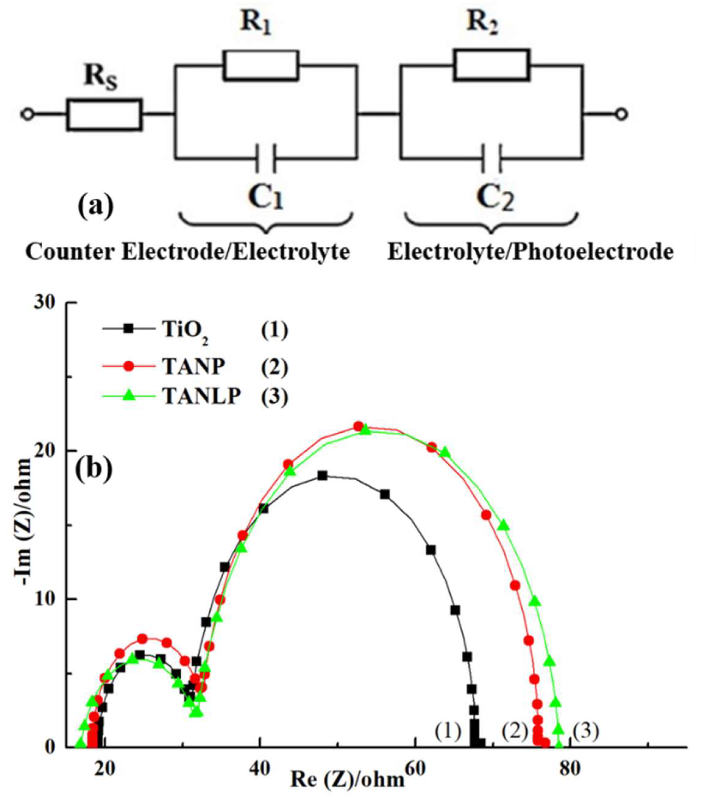
2.5. Measurement System

The photovoltaic parameters of the DSSCs were measured by the solar simulator (MFS-PV-Basic-HMT, Taiwan) at a sunlight intensity of 100 mW/cm2. The Nyquist plot of interface impedance for the DSSCs was investigated by electrochemical impedance spectroscopy (BioLogic SP-150, France), and the frequency of measurement was set from 1 to 50 MHz. The morphology of the TiO2/Ag nanofibers was characterized by a field-emission scanning electron microscope (FE-SEM, Hitachi S4800-l, Japan). We used XRD to characterize the Ag/TiO2 nanofibers. The amount of absorbed dye molecules was determined by detaching the dye from the photoanode in 1M NaOH solution and measuring the absorption spectra of N3 solution on a UV–Vis spectrophotometer (Perkin Elmer precise Lambda 850, America). The UV–Vis spectrophotometer was also employed to measure the UV–vis absorption spectra of Ag/TiO2 NF. It was measured for the dye-sensitized solar cells by Incident Photon-to-electron Conversion Efficiency (IPCE). The Solar Cell Spectral Response Measurement System (IPCE, QE-R) was procured from Enlitech, Taiwan.

3. Results and Discussion

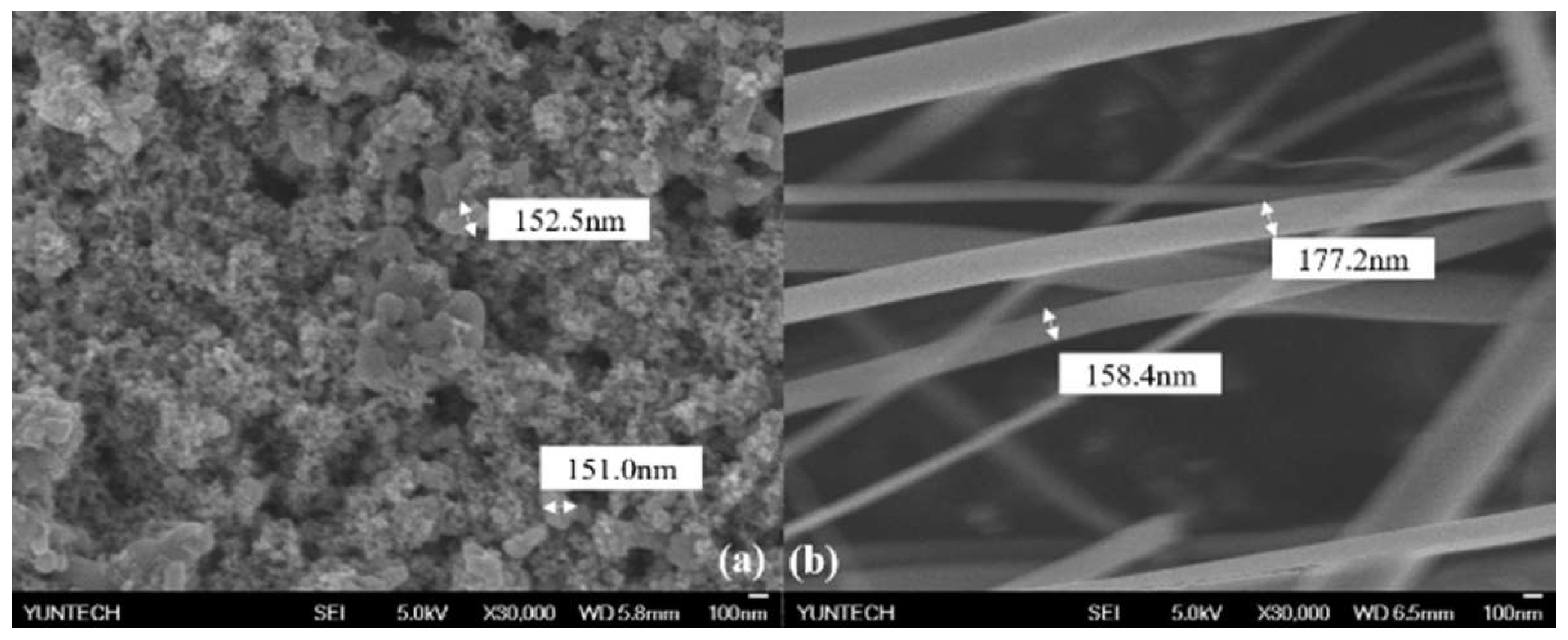
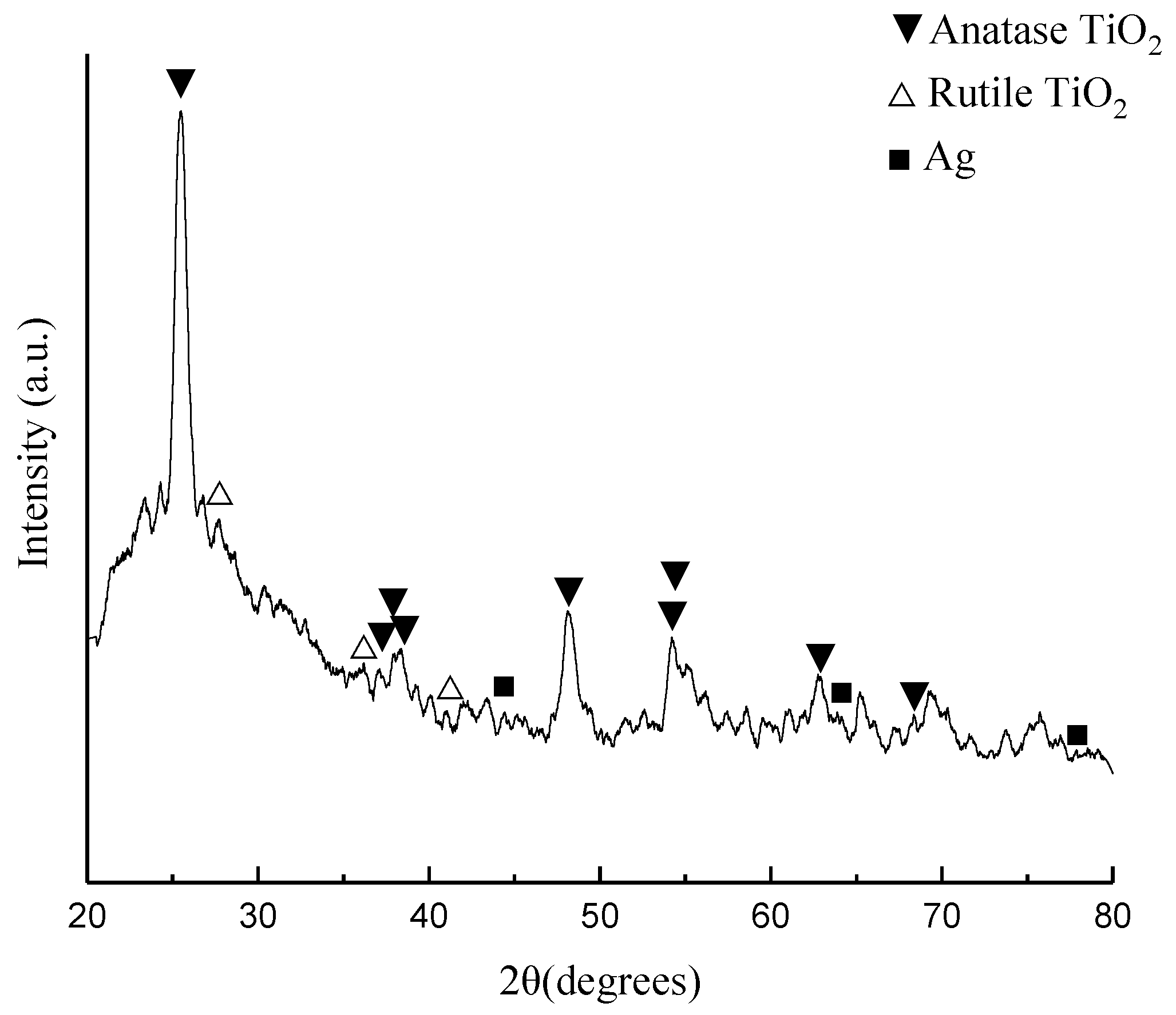
3.1. Morphology and Characterization of Ag/ TiO2 Nanofiber

Figure 2a, which we have characterized from our previous work [21], shows an image of the top view of the TiO2 layer. Figure 2b shows an image of the TiO2/Ag NF using field emission scanning electron microscopy (FE-SEM). From Figure 2b, the average diameter of the TiO2/Ag NF is about 168 nm. The connected nanofiber structure provides better charge transport paths and prohibits the recombination of electrons. Therefore, it can provide a better passageway for electron transmission and high charge mobility [22].
As shown in Figure 3, the Ag/ TiO2 nanofiber exhibits diffraction peaks of TiO2 anatase, TiO2 rutile and Ag (JCPDS file card number 21-1272) (JCPDS file card number 21-1276) (JCPDS file card number 043-0002) [23,24]. The diffraction peaks and reflections of the TiO2 anatase that presented in Ag/ TiO2 nanofiber are 2θ = 25.37° (1 0 1), 37.24° (1 0 3), 37.78° (0 0 4), 38.60° (1 1 2), 48.13° (2 0 0), 54.20° (1 0 5), 54.47° (2 1 1), 62.89° (2 1 3), 68.40° (2 2 0). The peaks and reflections of the TiO2 rutile that presented in Ag/ TiO2 nanofibers are 2θ = 27.72° (1 1 0), 36.27° (1 0 1), 41.09° (2 0 0). The diffraction peaks and reflections of the Ag that presented Ag/TiO2 nanofibers are 2θ = 44.40° (2 0 0), 64.13° (2 2 0), 77.92° (3 1 1). Because the content of Ag is low, the diffraction peak of Ag is not obvious [25,26].

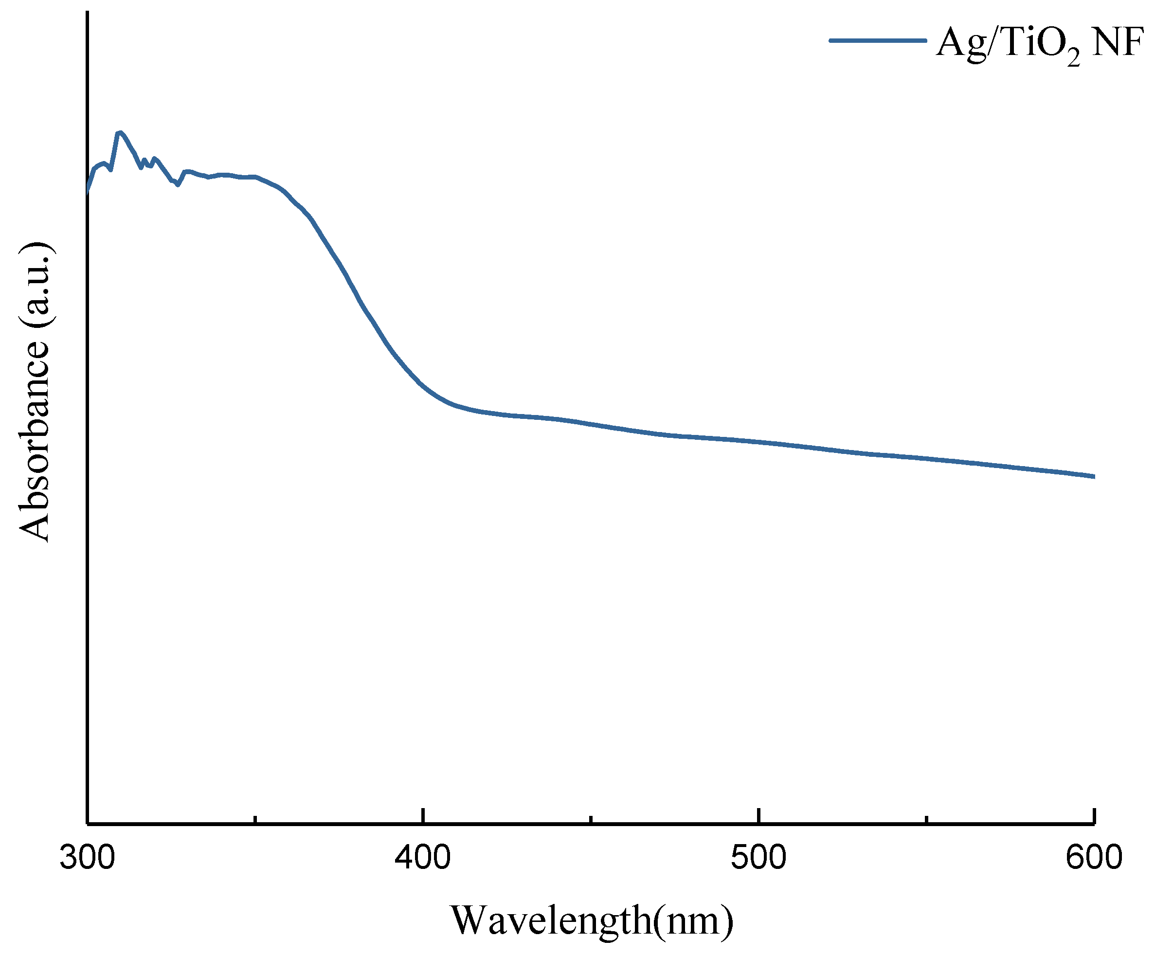
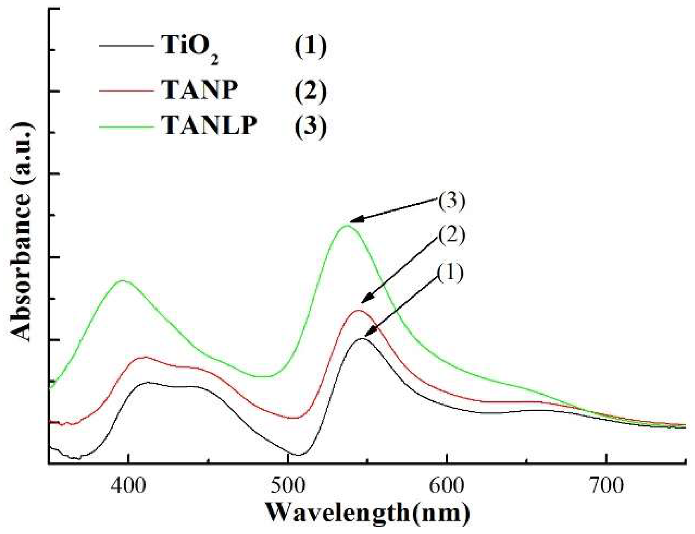
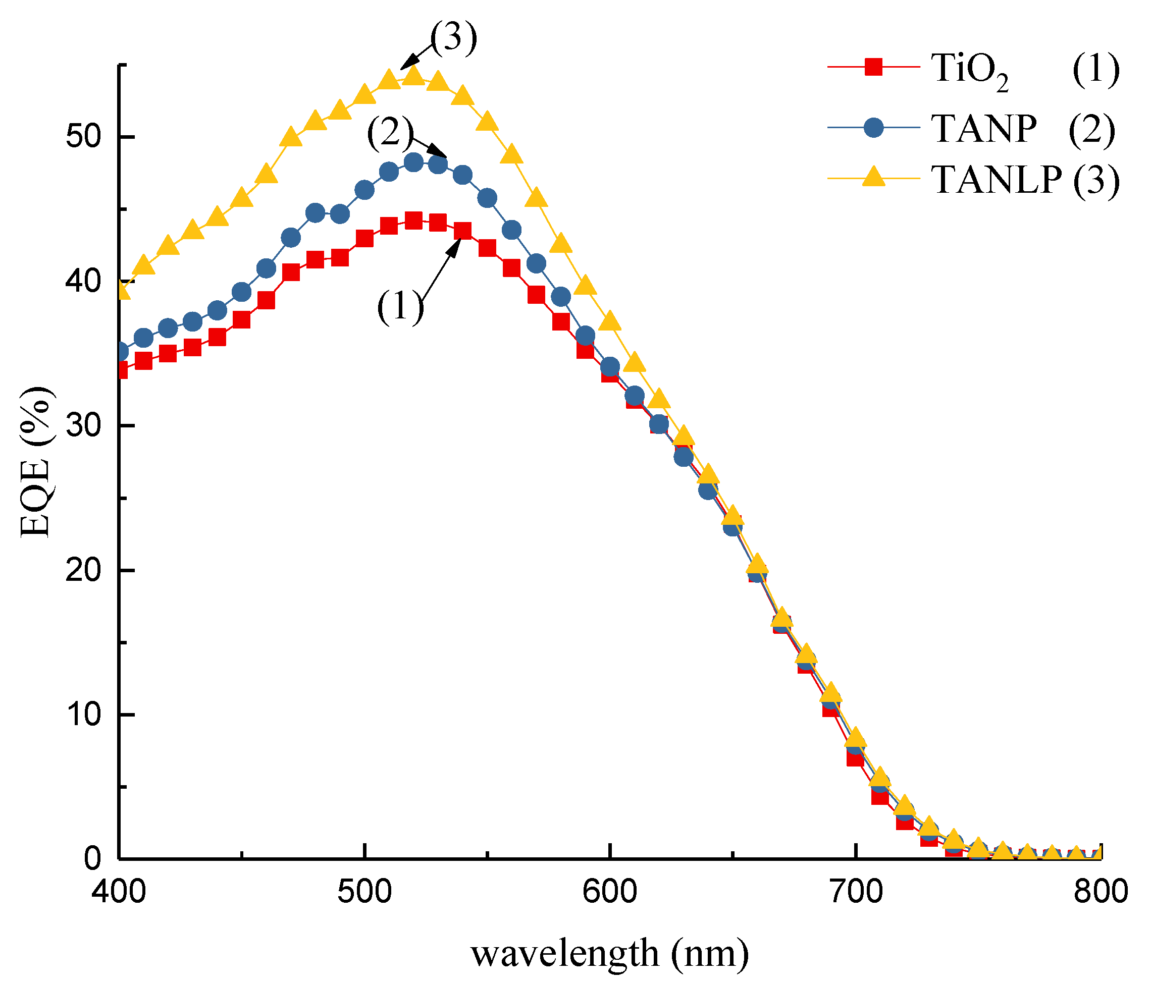
3.2. Ultraviolet–Visible Spectroscopy

The UV–vis absorption spectra of the Ag/TiO2 NFs is shown in Figure 4. The maximum absorption wavelength corresponding to the tangent line is 466.09 nm. Using the formula Eg = 1240/λ, the energy gap of Ag/TiO2 NF is about 2.66 eV [27]. The band gap of TiO2 is about 3 eV [28].
Figure 5 shows the UV-visible spectrum of the absorbed dye, which was determined by detaching the dye from the photoanode. The addition of TiO2/Ag NF in a photoelectrode (TANLP) increases the amount of dye absorbed in the photoelectrode and the addition of Ag nanoparticles (NP) can increase the absorption rate of the dye. According to the Mie theory [29], the increase in metal nanoparticles can be expected to lead to stronger absorption. In Figure 5, the dye solution obtained from TANLP shows highest absorbance, which suggests the largest amount of dye molecules incorporated into the photoanode in the DSSC. The Ag NP can distribute uniformly over the TiO2 surface.
We use the Beer–Lambert law to calculate the dye-loading on photoanode.
A = ε cl
Among them, A is the absorbance, ε is the molar extinction coefficient, c is the concentration of solution, and l is the length of optical path [30]. The literature shows that the molar absorption coefficient of the N3 dye is about 14,000 M−1cm−1 at 538 nm [31]. We use the Beer–Lambert law to estimate the dye-loading as shown in Table 1.

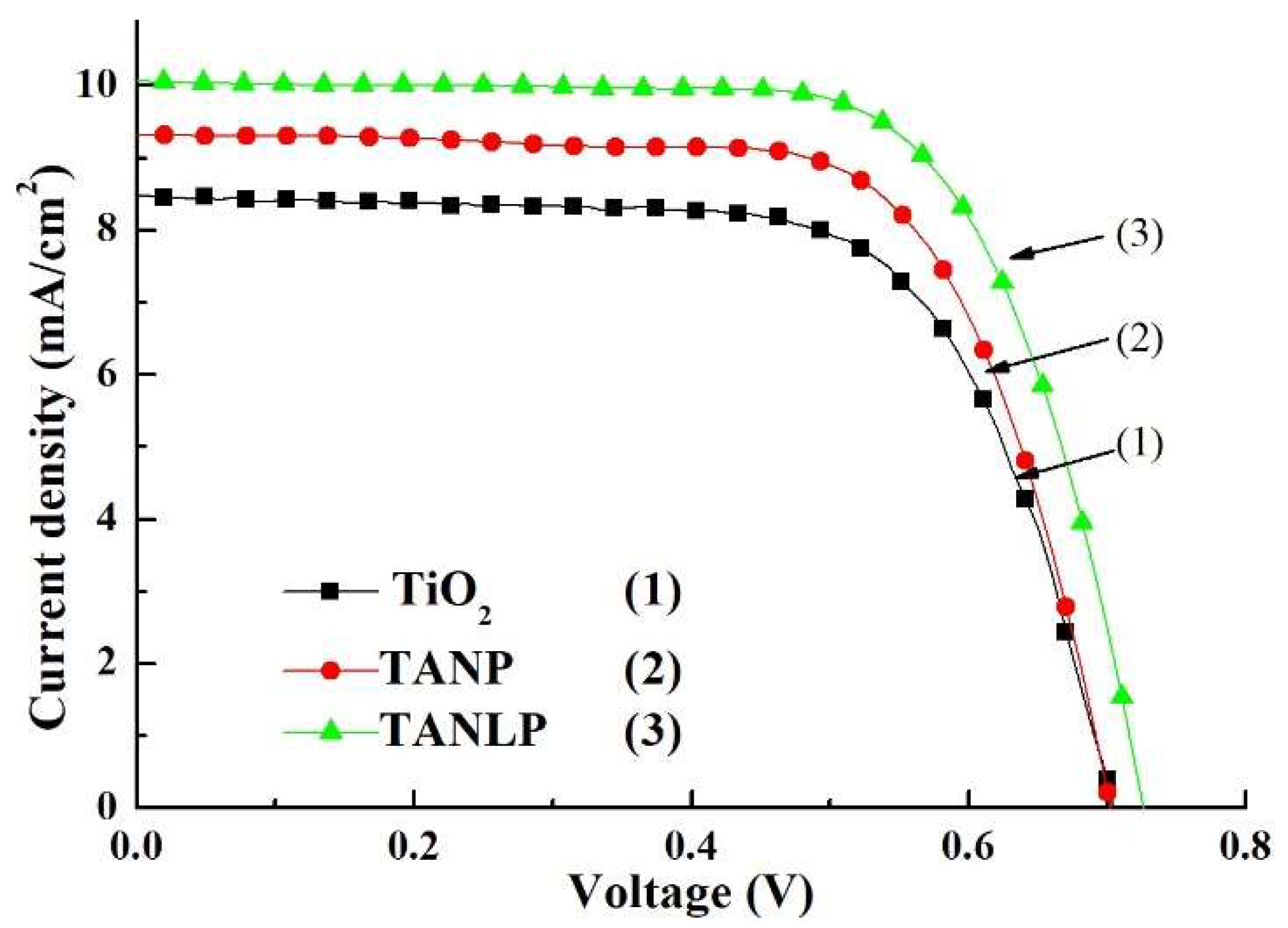
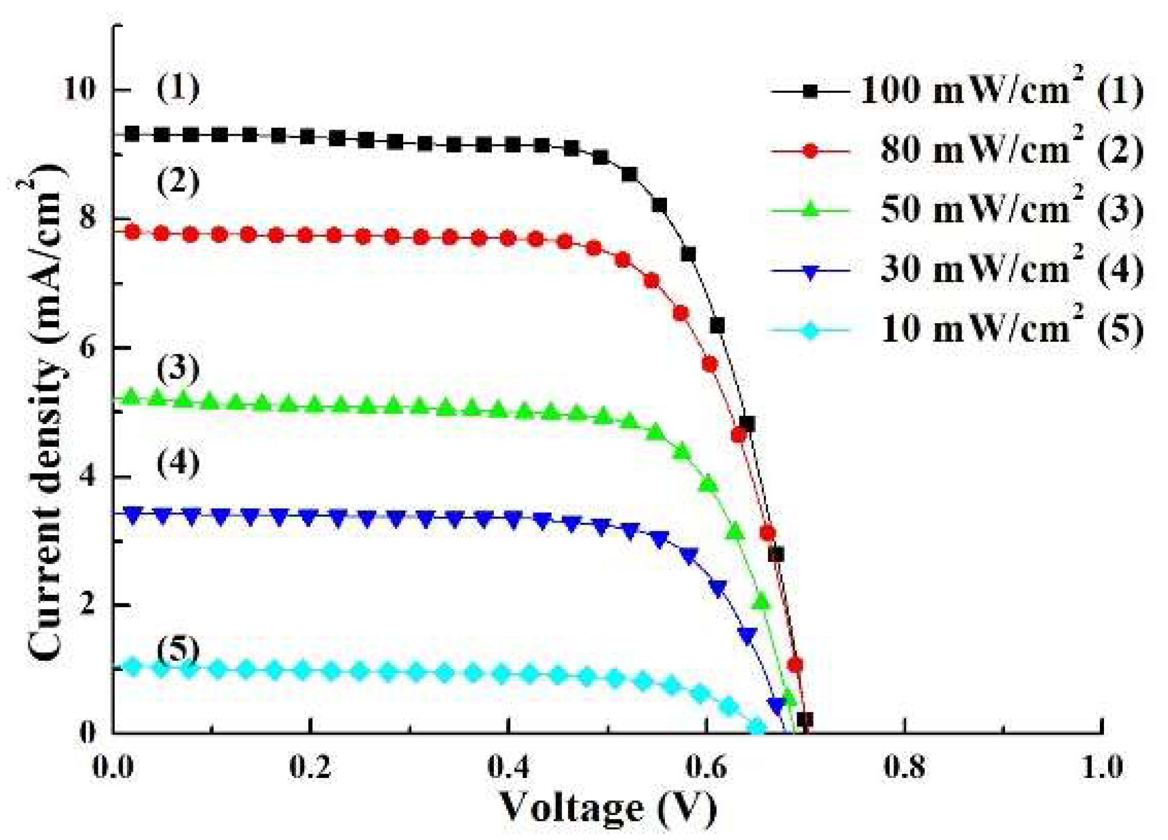
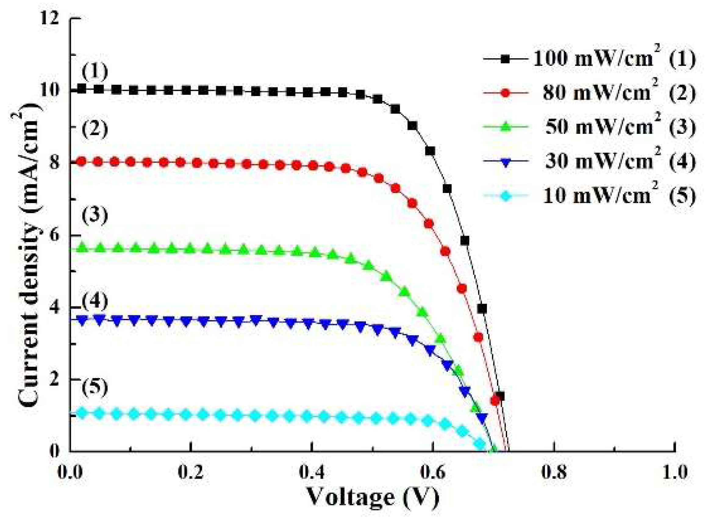
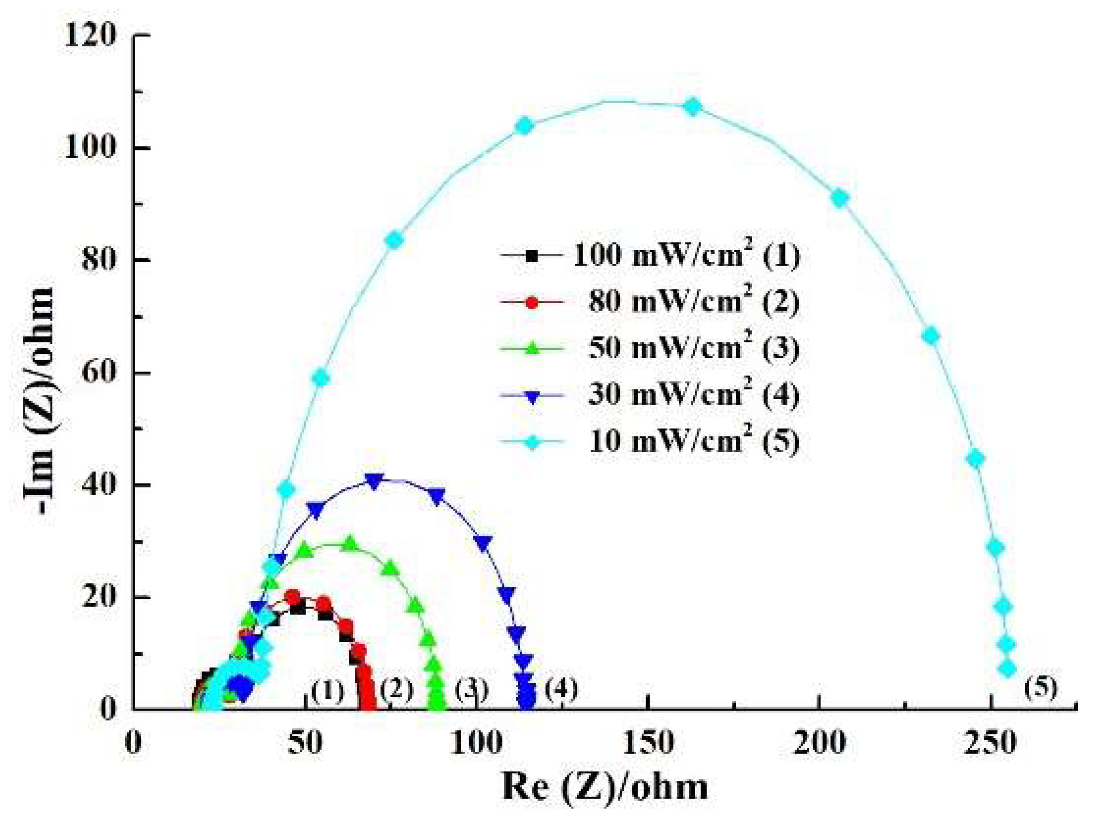
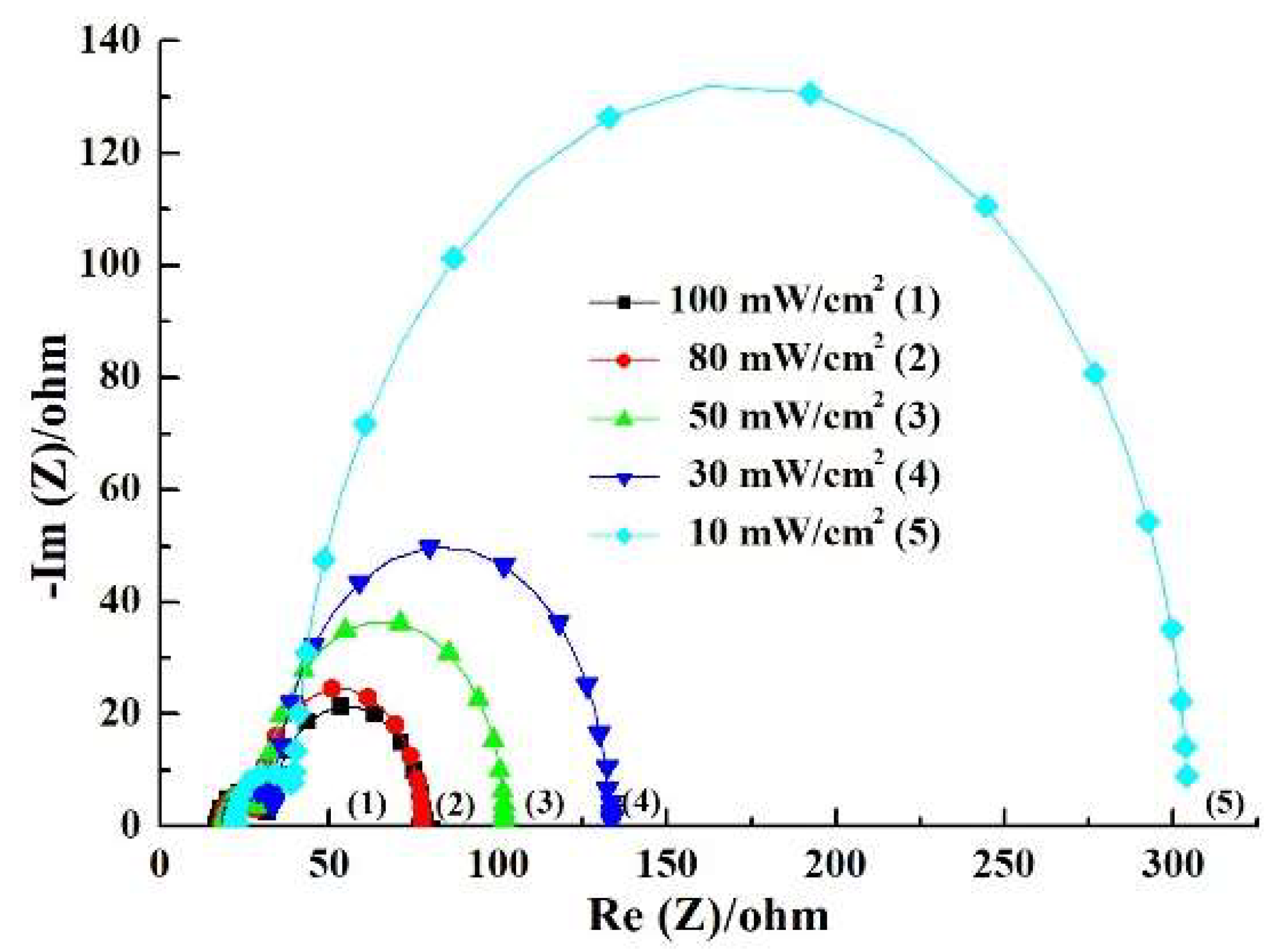
3.3. Measurement for the Photovoltaic Parameters of the DSSC

Figure 6 shows the I-V curve of the DSSCs under dark conditions.
Figure 7 shows the current density–voltage (J–V) curves for DSSCs with different photoelectrodes. The TANLP revealed an optimal open-circuit voltage (VOC), short-circuit current density (JSC), fill factor (FF), and photovoltaic conversion efficiency (η), which are 0.75 V, 11.35 mA/cm2, 61.28%, and 5.03%, respectively. The enhanced photovoltaic conversion efficiency was obvious for DSSC based on TANLP because Ag NPs could exhibit a strong scattering effect to improve light harvesting [32], which causes a higher short-circuit current density. The photoelectric properties of the DSSC based on TANP are significantly less than TANLP. That could lead to the silver nanoparticles being distributed uniformly over the surface, which suppresses recombination and more effective utilization of the visible-light radiation [33].
Figure 8a shows the equivalent circuit for DSSC in our research. The RS is the wire resistance. In addition, the first semicircle at high frequency is R1, which is the resistance of the interface between the electrolyte and counter electrode, and the second semicircle at intermediate frequency is R2, which is the resistance of interface between electrolyte and photoelectrode [34,35]. Moreover, we measure the DSSCs at direct current, which can neglect the capacitance. Figure 8b is the Nyquist plots of DSSCs with different photoelectrodes. We compare DSSCs with different photoelectrodes. The highest R2 is from TANLP at 46 ohms. The high R2 indicates the reduced probability of charge transfer capacity, which was discussed in our previous study [21].
The Incident Photon-to-electron Conversion Efficiency (IPCE) is the ratio of the number of electrons collected by a solar cell to the number of photons of a given energy incident on the solar cell. Figure 9 shows the IPCE spectrum of DSSCs with different photoelectrodes with wavelengths from 400 to 800 nm. TANLP has a significant improvement in IPCE.

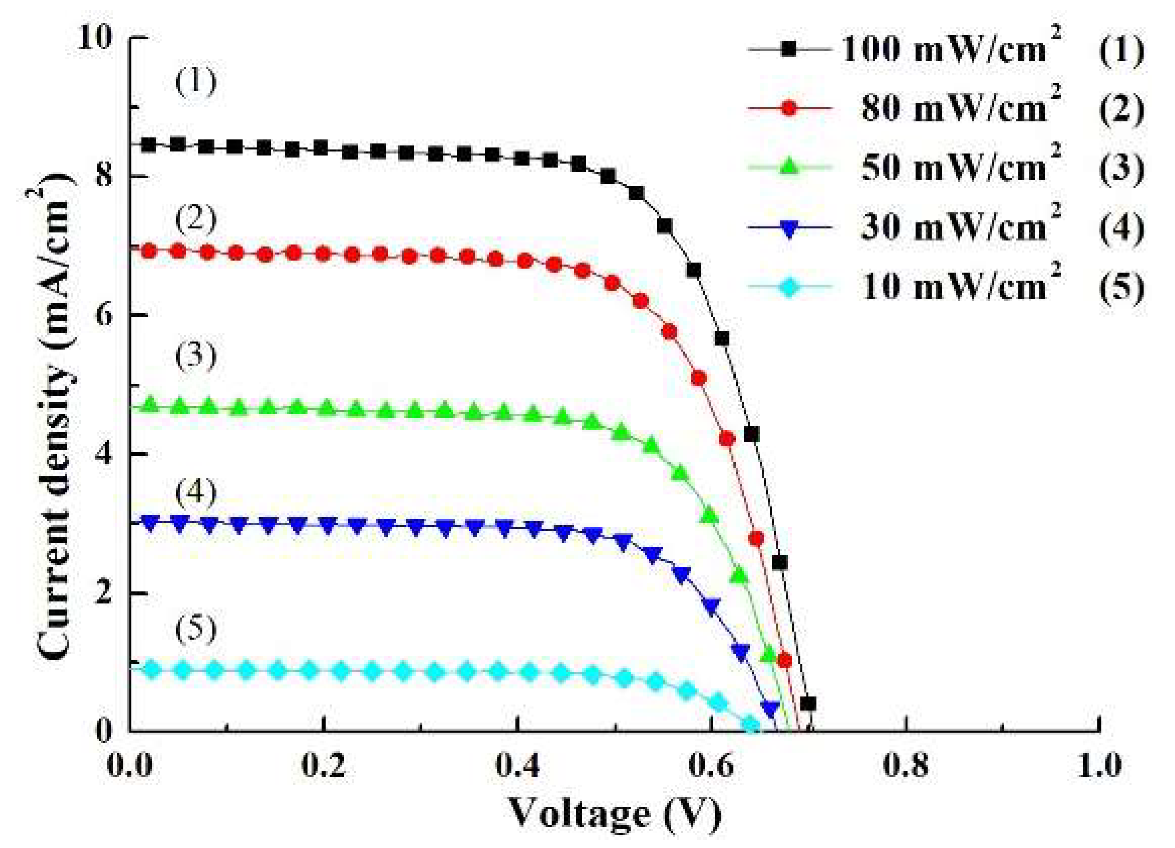
3.4. Performance of the DSSC Under Different Illuminations

Table 2, Table 3 and Table 4 display the photovoltaic parameters of the DSSCs with photoelectrodes under different illuminations. Figure 10, Figure 11 and Figure 12 show the J–V curves of DSSCs with photoelectrodes under different illuminations. As the light intensity is decreased from 100 to 10 mW/cm2, the JSC and VOC are gradually weakened; in particular, the JSC decline is more obvious. When the light intensity is decreased from 100 mW/cm2 to 30 mW/cm2, the optimal photovoltaic conversion efficiency (η) of the DSSC is under 30 mW/cm2. From Table 4 and Figure 12, when the light intensity is 30 mW/cm2, the photovoltaic parameters of DSSC based on TANLP are: 0.70 V in VOC, 3.67 in JSC, 72.66% in FF and 6.23% in η.
The photovoltaic parameters of the DSSCs based on TANLP have a very clear improvement in photovoltaic parameters. As mentioned earlier, the photoelectric properties of the DSSC based on TANP were significantly less than TANLP-based DSSC. Because the Ag NPs distribute uniformly over the surface, which suppressed recombination and caused a more effective utilization of the visible-light radiation [33]. From Table 2, Table 3 and Table 4, both JSC and VOC are reduced because the light intensity was reduced from 100 mW/cm2 to 10 mW/cm2, which means that the output power is reduced. In other words, we can improve the utilization of optical power under low illumination. The photon amount is decreased as the light intensity decreases, which causes the decrease in the dye molecules being excited. Therefore, the JSC is significantly reduced. The lower JSC could be attributed to the reduction in the electron recombination rate due to the decrease in the concentration of photogenerated electrons [36]. The DSSCs could decrease recombination reactions to enhance η under low illumination. The reduction in VOC is not significant, and is correlated with material properties.
Figure 13, Figure 14 and Figure 15 show Nyquist plots of DSSCs based on TiO2, TANP, and TANLP photoelectrodes, respectively, under different illumination. The corresponding electrochemical impedance parameters are listed in Table 2, Table 3 and Table 4, respectively. From the electrochemical impedence spectroscopy (EIS) measurements, we can find that the value of R2 gets larger with decreasing intensity. The R2 of the DSSC based on TiO2 increases from 36.91 Ω to 218.70 Ω, and the R2 of the DSSC based on TANLP increases from 43.40 Ω to 265.13 Ω. Because the amount of photo-generated electrons is decreased, the probability of recombination between the photo-generated electron and holes in the electrolyte can be reduced, which results in an increase in R2. Similarly, the value of R1 gets larger with decreasing intensity, which is due to the reduction in the amount of photo-generated electrons. The decrease in the amount of photo-generated electrons means the probability of recombination is diminished. In conclusion, the R1 and R2 are the interface impedances that represent the photo-generated electron degree of difficulty to recombine with the holes in the electrolyte. The suppression of electron recombination greatly reduces the electronic loss of DSSC [8,37], and this was the reason for the increase in fill factor, and thus the photovoltaic efficiency can be enhanced [38]. The highest efficiency is observed under an intensity of 30 mW/cm2. When the intensity keeps reducing to 10 mW/cm2, the value of R2 becomes several times larger than that with 30 mW/cm2. Under such light illumination, the number of photoelectrons generated within the DSSC is very low, resulting in a lower photovoltaic efficiency.
The electron lifetime is calculated by the equation (τ) = R2 × C2 [39]. The electronic lifetime of the DSSCs with various photoanaodes under various illuminations is shown in Table 5. When the light intensity decreases, the electron lifetime gradually increases.

4. Conclusions

In summary, the properties of DSSCs with two structures using nanofibers under low illumination have been investigated. The TANLP-based DSSC has the best photovoltaic conversion efficiency of 5.13%. The experimental results suggest that the TANLP-based DSSC has better photovoltaic performances than TNAP-based DSSC. This results in a suppressed recombination and a more effective utilization of the visible-light radiation. From this study, the highest efficiencies are observed under the intensity of 30 mW/cm2 for TANLP-based DSSC, and the maximum efficiency of 6.23% is achieved. The superiority of the dye-sensitized solar cell (DSSC) is utilized in low light illumination, while DSSCs are promising in indoor applications.

Author Contributions

Conceptualization, J.-C.C. and Y.-H.N.; data curation, H.-H.C. and Y.-H.N.; formal analysis, H.-H.C., P.-Y.K., C.-H.L., J.-C.C., and Y.-H.N.; funding acquisition, J.-C.C. and Y.-H.N.; investigation, H.-H.C., G.-M.H., C.-C.K., H.-H.H., Z.-R.Y., and J.-X.C.; methodology, H.-H.C. and Y.-H.N.; resources, J.-C.C. and Y.-H.N.; validation, C.-H.L., Y.-H.N., and P.-Y.K.; writing—original draft, H.-H.C. and M.R.; writing—review & editing, J.-C.C., H.-H.C., and Y.-H.N. All authors have read and agreed to the published version of the manuscript.

Funding

This research was funded by Ministry of Science and Technology, Taiwan, under the contract MOST 108-2221-E-224-019 and MOST 108-2221-E-224-020.

Acknowledgments

This study has been supported by Ministry of Science and Technology, Taiwan, under the contract MOST 108-2221-E-224-019 and MOST 108-2221-E-224-020.

Conflicts of Interest

The authors declare no conflict of interest.

References

  1. O’regan, B.; Grätzel, M. A low-cost, high-efficiency solar cell based on dye-sensitized colloidal tio 2 films. Nature 1991, 353, 737–740. [Google Scholar] [CrossRef]
  2. Nazeeruddin, M.K.; Baranoff, E.; Grätzel, M. Dye-sensitized solar cells: A brief overview. Sol. Energy 2011, 85, 1172–1178. [Google Scholar] [CrossRef]
  3. Yella, A.; Lee, H.-W.; Tsao, H.N.; Yi, C.; Chandiran, A.K.; Nazeeruddin, M.K.; Diau, E.W.-G.; Yeh, C.-Y.; Zakeeruddin, S.M.; Grätzel, M. Porphyrin-sensitized solar cells with cobalt (ii/iii)–based redox electrolyte exceed 12 percent efficiency. Science 2011, 334, 629–634. [Google Scholar] [CrossRef]
  4. Balasingam, S.K.; Lee, M.; Kang, M.G.; Jun, Y. Improvement of dye-sensitized solar cells toward the broader light harvesting of the solar spectrum. Chem. Commun. 2013, 49, 1471–1487. [Google Scholar] [CrossRef] [Green Version]
  5. Qiu, J.; Guo, M.; Wang, X. Electrodeposition of hierarchical zno nanorod-nanosheet structures and their applications in dye-sensitized solar cells. ACS Appl. Mat. Interfaces 2011, 3, 2358–2367. [Google Scholar] [CrossRef] [PubMed]
  6. Michaels, H.; Rinderle, M.; Freitag, R.; Benesperi, I.; Edvinsson, T.; Socher, R.; Gagliardi, A.; Freitag, M.J.C.S. Dye-sensitized solar cells under ambient light powering machine learning: Towards autonomous smart sensors for the internet of things. R. Soc. Chem. 2020, 11, 2895–2906. [Google Scholar] [CrossRef] [Green Version]
  7. Vaghasiya, J.V.; Sonigara, K.K.; Suresh, L.; Panahandeh-Fard, M.; Soni, S.S.; Tan, S.C. Efficient power generating devices utilizing low intensity indoor lights via non-radiative energy transfer mechanism from organic ionic redox couples. Nano Energy 2019, 60, 457–466. [Google Scholar] [CrossRef]
  8. Freitag, M.; Teuscher, J.; Saygili, Y.; Zhang, X.; Giordano, F.; Liska, P.; Hua, J.; Zakeeruddin, S.M.; Moser, J.-E.; Grätzel, M.J.N.P. Dye-sensitized solar cells for efficient power generation under ambient lighting. Nat. Photonics 2017, 11, 372. [Google Scholar] [CrossRef]
  9. Chou, J.; Kuo, C.; Kuo, P.; Lai, C.; Nien, Y.; Liao, Y.; Ko, C.; Yang, C.; Wu, C. The retardation structure for improvement of photovoltaic performances of dye-sensitized solar cell under low illumination. IEEE J. Photovoltaics 2019, 9, 926–933. [Google Scholar] [CrossRef]
  10. Hezam, A.; Namratha, K.; Drmosh, Q.A.; Chandrashekar, B.N.; Jayaprakash, G.K.; Cheng, C.; Srikanta Swamy, S.; Byrappa, K. Electronically semitransparent zno nanorods with superior electron transport ability for dsscs and solar photocatalysis. Ceram. Int. 2018, 44, 7202–7208. [Google Scholar] [CrossRef]
  11. Kilic, B. Produce of carbon nanotube/zno nanowires hybrid photoelectrode for efficient dye-sensitized solar cells. J. Mater. Sci. Mater. Electron. 2019, 30, 3482–3487. [Google Scholar] [CrossRef]
  12. Guo, Z.; Chen, Y.; Lu, N.L. Nanocomposite structures related to electrospun nanofibers for highly efficient and cost-effective dye-sensitized solar cells. In Multifunctional Nanocomposites for Energy and Environmental Applications; Wiley: Hoboken, NJ, USA, 2018; pp. 113–133. [Google Scholar]
  13. Marimuthu, T.; Anandhan, N.; Thangamuthu, R. Electrochemical synthesis of one-dimensional zno nanostructures on zno seed layer for dssc applications. Appl. Surf. Sci. 2018, 428, 385–394. [Google Scholar] [CrossRef]
  14. Devulapally, K.; Vardhaman, A.K.; Katakam, R.; Upadhyaya, H.M.; Rajeswari, R.; Islavath, N.; Giribabu, L. One-dimensional hollow metal-complex as catalytic electrode for dye-sensitized solar cells. Sol. Energy 2018, 174, 502–507. [Google Scholar] [CrossRef]
  15. Gao, X.; Kong, C.-P.; Jia, R.; Jian, W.; Wang, J.; Bai, F.-Q.; Zhang, H.-X. Influence of one-dimensional TiO2 nanotube on interfacial electron transfer in dye-sensitized solar cells: Insights from theoretical investigation. Sol. Energy 2018, 176, 545–555. [Google Scholar] [CrossRef]
  16. Joshi, P.; Zhang, L.; Davoux, D.; Zhu, Z.; Galipeau, D.; Fong, H.; Qiao, Q. Composite of TiO2 nanofibers and nanoparticles for dye-sensitized solar cells with significantly improved efficiency. Energy Environ. Sci. 2010, 3, 1507–1510. [Google Scholar] [CrossRef]
  17. Madhavan, A.; Kalluri, S.; Chacko, D.; Arun, T.A.; Nagarajan, S.; Subramanian, K.R.V.; Nair, S.; Nair, S.; Balakrishnan, A. Electrical and optical properties of electrospun TiO2-graphene composite nanofibers and its application as dssc photo-anodes. RSC Adv. 2012, 2, 2012. [Google Scholar] [CrossRef]
  18. Zheng, F.; Zhu, Z. Preparation of the au@TiO2 nanofibers by one-step electrospinning for the composite photoanode of dye-sensitized solar cells. Mater. Chem. Phys. 2018, 208, 35–40. [Google Scholar] [CrossRef]
  19. Wu, W.-Y.; Hsu, C.-F.; Wu, M.-J.; Chen, C.-N.; Huang, J.-J. Ag–TiO2 composite photoelectrode for dye-sensitized solar cell. Appl. Phys. A 2017, 123, 357. [Google Scholar] [CrossRef]
  20. Vaghasiya, J.V.; Sonigara, K.K.; Fadadu, K.B.; Soni, S.S. Hybrid agnp–TiO2 thin film based photoanode for dye sensitized solar cell. Perspect. Sci. 2016, 8, 46–49. [Google Scholar] [CrossRef] [Green Version]
  21. Nien, Y.-H.; Chen, H.-H.; Hsu, H.-H.; Kuo, P.-Y.; Chou, J.-C.; Lai, C.-H.; Hu, G.-M.; Kuo, C.-H.; Ko, C.-C. Enhanced photovoltaic conversion efficiency in dye-sensitized solar cells based on photoanode consisting of TiO2/go/ag nanofibers. Vacuum 2019, 167, 47–53. [Google Scholar] [CrossRef]
  22. Hussein, A.M.; Iefanova, A.V.; Koodali, R.T.; Logue, B.A.; Shende, R.V. Interconnected ZRO2 doped zno/ TiO2 network photoanode for dye-sensitized solar cells. Energy Rep. 2018, 4, 56–64. [Google Scholar] [CrossRef]
  23. Thamaphat, K.; Limsuwan, P.; Ngotawornchai, B.J.K.J. Phase characterization of TiO2 powder by xrd and tem. IJSRST 2008, 42, 357–361. [Google Scholar]
  24. Philip, D. Biosynthesis of au, ag and au–ag nanoparticles using edible mushroom extract. Spectrochim. Acta Part A Mol. Biomol. Spectrosc. 2009, 73, 374–381. [Google Scholar] [CrossRef] [PubMed]
  25. Rao, T.N.; Riyazuddin; Babji, P.; Ahmad, N.; Khan, R.A.; Hassan, I.; Shahzad, S.A.; Husain, F.M. Green synthesis and structural classification of acacia nilotica mediated-silver doped titanium oxide (ag/TiO2 spherical nanoparticles: Assessment of its antimicrobial and anticancer activity. Saudi J. Biol. Sci. 2019, 26, 1385–1391. [Google Scholar] [CrossRef] [PubMed]
  26. Abbad, S.; Guergouri, K.; Gazaout, S.; Djebabra, S.; Zertal, A.; Barille, R.; Zaabat, M. Effect of silver doping on the photocatalytic activity of TiO2 nanopowders synthesized by the sol-gel route. J. Environ. Chem. Eng. 2020, 8, 103718. [Google Scholar] [CrossRef]
  27. Dong, F.; Zhang, Y.; Zhang, S. Photocatalysis for environmental applications. Front. Chem. 2019, 7, 303. [Google Scholar] [CrossRef] [Green Version]
  28. Tunc, I.; Bruns, M.; Gliemann, H.; Grunze, M.; Koelsch, P.J.S.; Analysis, I. Bandgap determination and charge separation in ag@TiO2 core shell nanoparticle films. Surf. Interface Anal. 2010, 42, 835–841. [Google Scholar] [CrossRef]
  29. Yun, J.; Hwang, S.H.; Jang, J. Fabrication of au@ag core/shell nanoparticles decorated TiO2 hollow structure for efficient light-harvesting in dye-sensitized solar cells. ACS Appl. Mater. Interfaces 2015, 7, 2055–2063. [Google Scholar] [CrossRef]
  30. Gosnell, J.D.; Weiss, S.M. Light scattering by white-emitting cdse nanocrystals and traditional yag: Ce3+ phosphor particles. Mater. Res. Soc. Symp. Proc. 2009, 1148. [Google Scholar]
  31. Ramamurthy, V.; Schanze, K.S. Semiconductor Photochemistry and Photophysics/Volume ten; CRC Press: Boca Raton, FL, USA, 2003; Volume 10. [Google Scholar]
  32. Saud, P.S.; Pant, B.; Twari, A.P.; Ghouri, Z.K.; Park, M.; Kim, H.-Y. Effective photocatalytic efficacy of hydrothermally synthesized silver phosphate decorated titanium dioxide nanocomposite fibers. J. Colloid Interface Sci. 2016, 465, 225–232. [Google Scholar] [CrossRef]
  33. Wolf, M.; Rauschenbach, H. Series resistance effects on solar cell measurements. Adv. Energy Convers. 1963, 3, 455–479. [Google Scholar] [CrossRef]
  34. Sacco, A. Electrochemical impedance spectroscopy: Fundamentals and application in dye-sensitized solar cells. Renew. Sustain. Energy Rev. 2017, 79, 814–829. [Google Scholar] [CrossRef]
  35. Fernández Pulido, Y.; Blanco, C.; Anseán, D.; García, V.M.; Ferrero, F.; Valledor, M. Determination of suitable parameters for battery analysis by electrochemical impedance spectroscopy. Measurement 2017, 106, 1–11. [Google Scholar] [CrossRef] [Green Version]
  36. Zhai, P.; Lee, H.; Huang, Y.-T.; Wei, T.-C.; Feng, S.-P. Study on the blocking effect of a quantum-dot TiO2 compact layer in dye-sensitized solar cells with ionic liquid electrolyte under low-intensity illumination. J. Power Sources 2016, 329, 502–509. [Google Scholar] [CrossRef]
  37. Pal, A.; Jana, A.; Bhattacharya, S.; Datta, J. Spr effect of agnps decorated TiO2 in dssc using tpmpi in the electrolyte: Approach towards low light trapping. Electrochim. Acta 2017, 243, 33–43. [Google Scholar] [CrossRef]
  38. Salvador, P.; Hidalgo, M.G.; Zaban, A.; Bisquert, J. Illumination intensity dependence of the photovoltage in nanostructured TiO2 dye-sensitized solar cells. J. Phys. Chem. B 2005, 109, 15915–15926. [Google Scholar] [CrossRef]
  39. Mozaffari, S.A.; Ranjbar, M.; Kouhestanian, E.; Salar Amoli, H.; Armanmehr, M.H. An investigation on the effect of electrodeposited nanostructured zno on the electron transfer process efficiency of TiO2 based dssc. Mat. Sci. Semicond. Process. 2015, 40, 285–292. [Google Scholar] [CrossRef]
Figure 1. Structure of the dye-sensitized solar cells (DSSCs) with (a) TANLP and (b) TANP.
Energies 13 02248 g001
Figure 2. Top view images of (a) pristine TiO2 and (b) TiO2/Ag nanofibers (NFs).
Energies 13 02248 g002
Figure 3. The XRD analysis of Ag/ TiO2 nanofibers.
Energies 13 02248 g003
Figure 4. The UV–vis absorption spectra of Ag/TiO2 NF.
Energies 13 02248 g004
Figure 5. UV-visible absorption spectra of dye-loading of different photoelectrodes.
Energies 13 02248 g005
Figure 6. The I-V characteristics of TiO2, TANP, and TANLP in dark conditions.
Energies 13 02248 g006
Figure 7. Current density–voltage curves of the DSSCs with different photoelectrodes.
Energies 13 02248 g007
Figure 8. Electrochemical Impedance Spectroscopy of the DSSCs based on different photoelectrodes—(a) the equivalent circuit and (b) Nyquist plots for DSSCs with different photoelectrodes of the DSSC.
Energies 13 02248 g008
Figure 9. The Incident Photon-to-electron Conversion Efficiency (IPCE) spectrum for DSSCs with different photoelectrodes.
Energies 13 02248 g009
Figure 10. Current density–voltage curves of the DSSC based on TiO2 under different illuminations.
Energies 13 02248 g010
Figure 11. Current density–voltage curves of the DSSC based on TANP under different illuminations.
Energies 13 02248 g011
Figure 12. Current density–voltage curves of the DSSC based on TANLP under different illuminations.
Energies 13 02248 g012
Figure 13. Nyquist plots for DSSCs based on TiO2 under different illuminations.
Energies 13 02248 g013
Figure 14. Nyquist plots for DSSCs based on TANP under different illuminations.
Energies 13 02248 g014
Figure 15. Nyquist plots for DSSCs based on TANLP under different illuminations.
Energies 13 02248 g015
Table 1. Amount of dye-loading of N3 on photoanode.
PhotoanodeDye-Loading of N3 (nmol/cm2)
TiO225.63
TANP36.89
TANLP67.76
Table 2. Parameters of DSSC based on TiO2.
Intensity
(mW/cm2)
RS
(Ω)
R1
(Ω)
R2
(Ω)
JSC
(mA/cm2)
VOC
(V)
F. F.
(%)
η
(%)
10019.097.8836.918.36 ± 0.030.70 ± 0.0268.12 ± 0.183.99 ± 0.15
8019.498.4540.496.94 ± 0.030.69 ± 0.0269.91 ± 0.144.24 ± 0.13
5020.099.0059.354.69 ± 0.020.68 ± 0.0171.02 ± 0.164.53 ± 0.11
3022.179.7182.553.01 ± 0.020.67 ± 0.0271.95 ± 0.154.84 ± 0.12
1022.7813.38218.700.91 ± 0.010.66 ± 0.0170.51 ± 0.134.22 ± 0.14
Table 3. Parameters of DSSC based on TANP.
Intensity
(mW/cm2)
RS
(Ω)
R1
(Ω)
R2
(Ω)
JSC
(mA/cm2)
VOC
(V)
F. F.
(%)
η
(%)
10018.379.1142.729.31 ± 0.030.71 ± 0.0169.68 ± 0.534.61 ± 0.15
8018.849.7446.947.80 ± 0.020.70 ± 0.0270.46 ± 0.494.81 ± 0.13
5019.5410.4268.695.22 ± 0.030.69 ± 0.0271.52 ± 0.535.16 ± 0.12
3022.0011.3495.483.41 ± 0.010.68 ± 0.0172.43 ± 0.515.60 ± 0.14
1022.7215.96252.461.04 ± 0.010.66 ± 0.0270.67 ± 0.534.83 ± 0.12
Table 4. Parameters of DSSC based on TANLP.
Intensity
(mW/cm2)
RS
(Ω)
R1
(Ω)
R2
(Ω)
JSC
(mA/cm2)
VOC
(V)
F. F.
(%)
η
(%)
10017.699.7043.4010.05 ± 0.090.73 ± 0.0169.92 ± 0.515.13 ± 0.16
8018.1710.2249.308.29 ± 0.120.72 ± 0.0270.75 ± 0.475.28 ± 0.14
5018.8910.9472.135.60 ± 0.140.71 ± 0.0171.84 ± 0.485.71 ± 0.12
3020.4112.84100.283.67 ± 0.130.70 ± 0.0172.66 ± 0.456.23 ± 0.16
1021.1517.05265.131.08 ± 0.130.69 ± 0.0270.83 ± 0.465.31 ± 0.13
Table 5. The electron lifetime of the DSSCs with various photoanaodes under various illuminations.
PhotoanodeElectron Lifetime under 100 mW/cm2(ms)Electron Lifetime under 80 mW/cm2(ms)Electron Lifetime under 50 mW/cm2(ms)Electron Lifetime under 30 mW/cm2(ms)Electron Lifetime under 10 mW/cm2(ms)
TiO227.1427.5334.4643.0068.32
TANP22.6223.5427.3231.5945.24
TANLP26.3427.7028.4630.7549.16

