Abstract
This study investigates the effect of waterproofing can on the electromagnetic performance and thermal characteristic of the electric motor, which is a major part of an integrated motor propulsor for unmanned vehicles. To satisfy the design target, the electromagnetic performance of a designed motor with variable thickness and materials of waterproofing can was examined by two-dimensional finite element analysis (FEA) considering its eddy current loss. The thermal problem of the motor with waterproofing was solved by using an analytical lumped parameter thermal network method based on the motor losses which was obtained from FEA. A 39-kW electric motor and proper waterproofing can be manufactured and tested to verify the analytical expectation.
1. Introduction
The integrated motor propulsor (IMP) exhibits many advantages compared to ordinary propulsors or thrusters, such as lower overall volume, higher power density, higher reliability, and lower noise [1,2,3]. Depending on the bearing position, IMP can be divided into two types: rim-bearing type and hub-bearing type [4,5,6]. The conceptual configuration of the rim-bearing type IMP system is illustrated in Figure 1. The considered IMP consists of a rim-driven motor (IMP motor), a fluid hydrodynamic bearing, and a propeller. The rotor of the IMP motor is part of the propeller rim, and the stator is embedded in the duct [7]. It can be seen that the interior of the IMP system would be immersed in the seawater. Therefore, to protect the motor from being corroded, the rotor will be sealed by carbon-fiber-reinforced plastic (CFRP), and the stator is totally closed and sealed by a welded can.
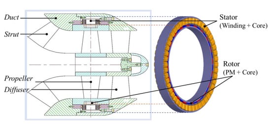
Figure 1.
Conceptual configuration of the proposed IMP system.
Although various papers have presented the design and optimization of a motor for an IMP system [1,2,3,8,9,10], researches related to the effect of waterproofing can on the electromagnetic and thermal performance of the motor are still rare. Previously, the authors have mainly concentrated on the design of a permanent-magnet (PM) motor of a rim bearing type IMP for unmanned underwater vehicle [11,12,13]. Those papers are related to a basic design process of the first prototype of an IMP motor that has not been considered waterproof.
In this paper, a welded can is considered and designed as a part of the electro-magnetic design process for waterproofing of the electric motor stator. The welded can is called the waterproofing can herein. However, waterproofing can be made of conductive material, so it will generate eddy current losses and as a result reduce the motor efficiency. Therefore, to achieve the design goal of the IMP motor, the performance of motor with variable thickness and materials of waterproofing can were examined and chose the proper can. In order to predict the eddy current loss of the waterproofing can, 2-dimensional (2-D) finite element analysis (FEA) is performed. Based on the losses obtained by FEA, the thermal problem was solved by using the lumped-parameter-thermal-network (LPTN) method. Considering the manufacturing cost and motor performance, the proper waterproofing can be selected and applied to the IMP motor. Several experiments were performed to validate the analytical expectation.
2. Prototype Specifications
Figure 2 shows the configuration of the IMP motor with waterproofing can for the stator. Table 1 shows the specifications of the IMP motor. As the seawater can enter the inside of motor, it also helps to reduce the motor temperature. Therefore, the motor can be designed with higher current density compared to totally-enclosed motors with natural cooling, which is 15 A/mm2 in this study. The performance of first prototype (IMP motor without waterproofing can) satisfies the requirement of output power and efficiency. In the load test, the first prototype has 46.4 kW at 80.2 A input current and 1020 rpm. Its power exceeds 20% of the requirement. The waterproofing can must be designed and selected such that its eddy current loss is less than 20% of the output power to meet the system requirement.
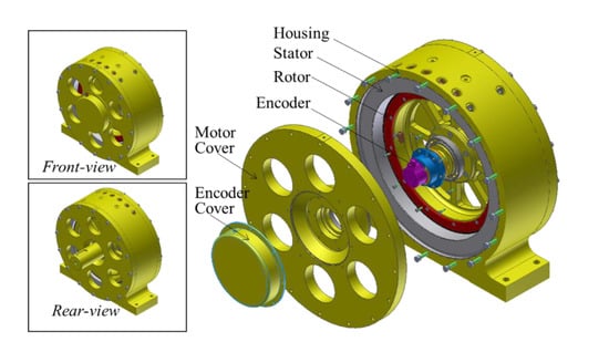
Figure 2.
Configuration of the IMP motor with waterproofing can for the stator.

Table 1.
Specifications of the IMP motor.
Table 2 shows the characteristics of waterproofing and sealing materials. The LD and TD in the table stand for the longitudinal and transversal directions respectively. The conductivity of CFRP in the cross-ply direction (CD) is able to be considered as the same value of the conductivity in the transversal direction [14]. If only the conductivity of Table 2 is considered, CFRP is the most suitable material for cans, but the epoxy that composes CFRP is not perfect for waterproofing, and CFRP is too expensive and difficult to make a shape for sealing the stator. Therefore, weldable materials were selected. Two materials which are 316L grade-stainless steel (SUS316L) and 718grade-inconel (Inconerl718) are examined as can material in term of low conductivity and rust prevention.
Table 2.
Characteristics of waterproofing and sealing materials.
3. Analysis Model and Methods
3.1. Analysis Model
For the second prototype design, there is no change in the dimensions and specifications of stator and rotor except waterproofing can. The material and thickness of waterproofing can be selected when the output power of the IMP motor with the can meet the system requirement. The waterproofing can be made into four thin plates, which are one internal, one outer, and two side plates. The outer plate, between the stator outer and housing inner surfaces, and the two side plates beside end-coil are unaffected by the main flux path. Therefore, the internal plate of the can, which is between stator inner and rotor outer surfaces, is only modeled to see the eddy current loss effect.
Figure 3 shows the 2-D FEA model including an internal plate of waterproofing can for electro-magnetic field analysis of IMP motor. When changing the can thickness, the magnetic air-gap is maintained and the mechanical air-gap changes. For instance, if the thickness of CFRP is 1 mm and the same thickness of waterproofing can also be used, the magnetic airgap is still 5 mm but the mechanical airgap becomes 3 mm.
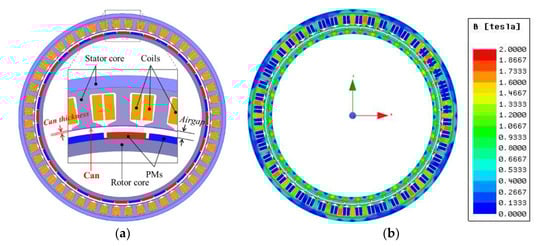
Figure 3.
(a) 2-D configuration of the designed model; (b) Flux distribution obtained from 2-D FEA.
If there is space between the inner surface of the stator core and the outer surface of the internal plate of the can, the eddy current loss on the can is lower and the efficiency is better due to the less affected by magnetic flux. However, for the effective manufacturing process of the can and avoiding roundness, the internal plate of the waterproofing can be considered to be attached next to the internal surface of the stator. Although there are conductivities in both the stator core and the waterproofing can, they are considered to be insulated to each other due to the polymer, which is used to fill inside of the can by vacuum impregnation.
3.2. Electromagnetic Analysis Method
The governing equation of 2-D FEA from Maxwell’s electro-magnetic equation is as follows [15,16]:
where ν is the magnetic reluctivity, is the magnetic vector potential, is the source current density of the coil, is the eddy current density, and is the equivalent magnetization current density. and can be expressed as follows:
where σ is the conductivity and μ0 is the magnetic permeability of free space. is the magnetization. The current occurred by gradient of electric potential, which is the voltage difference across the conductor’s end points, is not taken into account in this analysis model.
Under the sinusoidal flux conditions, core loss Pt is computed in the frequency domain as the following [15]:
where Ph, Pc, and Pe are hysteresis loss, eddy current loss, and excess loss components respectively. Kh, Kc, and Ke are the coefficient of each component. f is the frequency, Bm is the amplitude of the AC flux component, and d is the thickness of one lamination sheet. The classical eddy-current loss coefficient Kc is calculated directly Equation (5). The other coefficients, Kh and Ke can be derived using measured core loss curves obtained under each given frequency and flux density condition, as shown in Figure 4 and Table 3.
Pt = Ph + Pc + Pe = Khf (Bm)2 + Kc (fBm)2 + Ke (fBm)1.5
Kc = (π2σ d2) / 6
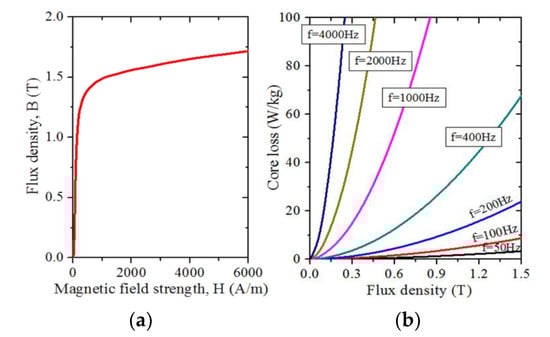
Figure 4.
Magnetic properties of S18-0.5t tested by Epstein test apparatus. (a) B-H curve. (b) Core loss curve.
Table 3.
Core loss data at various frequencies of S18-0.5t material.
3.3. Thermal Analysis Method
The thermal characteristic of IMP motor was calculated by an analytical LPTN method, using commercial software, Motor-CAD. Each single node in the network represents the components which have similar temperatures. Thermal resistances are used to separate nodes, and losses are modelled as the power source in the thermal network. The thermal transient problem is solved by calculating a set of nonlinear equations at each node:
where C is the heat capacitance, which is defined as C = ρVCP, T is the temperature rise, P is the power source, R is the thermal resistance, ρ is the density, V is the volume of the component, and CP is the thermal capacity of material [17].
Thermal resistances for radiation and convection are calculated by R = 1/hA, where h is the heat transfer coefficient and A is the surface area. Similarly, we can also determine the value of resistance for conduction. Since the thermal resistance will not be calculated if h is unknown, so h is the most important parameter to be considered. In the case of convective heat transfer, we considered mainly in air gap and housing outer. For natural convective heat transfer in the outer housing, the equations for determining heat transfer coefficient have been presented in another research [18].
Because the motor is placed inside the fluid tank (fluid can be water or engine oil), so the fluid is assumed to pass through air gap. Figure 5 shows the heat transfer paths in the air gap of IMP motor. The convective heat transfer coefficient for each side of the air gap is calculated using Equations (7)–(9) [18]:
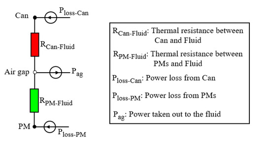
Figure 5.
Thermal circuit in the air gap.
In this study, Re < 2800 the flow is assumed to be fully laminar, so the corresponding Nu can be calculated by following equation:
where k is the fluid thermal conductivity, Dh is the hydraulic diameter, Dh = 2 × Air-gap, ν is the fluid velocity in the air-gap, μ is the kinematic viscosity of the fluid, and Pr is the Prandtl number.
4. Analysis and Experiment Results
4.1. Analysis Results
Depending on the variation of the waterproof can thickness and its materials, several analyses were performed, and the results are listed in Table 3.
M1 is the analysis model of the first prototype of IMP motor. When comparing the analysis results of M1 to test results of the first prototype, the power is 1.12 times lower in the condition of the same input current and the same speed. The main reason is because of the overhang, which is the difference between stator and rotor length in the axial direction. The analysis model depth is considered as 50 mm, while the stack lengths of rotor and stator in the prototype are different as listed in Table I. Since the overhang coefficient, which means the magnetic performance ratio of the overhang model to non-overhang model, is defined as various forms depending on the electric motor configurations [19,20,21], the overhang coefficient for torque in this research is decided as 1.12 considering the power difference ratio in the first prototype. Actually, the power difference ratio is the same as torque difference ratio because the speed and input current conditions were the same. The Torque_ovh in the Table 3 is multiplied by the overhang coefficient 1.12 and the torque obtained by 2D-FEA. The Power_ovh is calculated using the Torque_ovh value.
All of the models using Inconel718-M3, M5, M6-satisfies the output power condition, but the model using SUS316L meets the output power condition only when the can thickness is 0.6 mm. Although Inconel material was analytically reviewed because of its relatively low conductivity and high strength, the manufacturing cost was too expensive to use it in the second prototype. Considering the loss limit and fabrication cost, 0.6 mm thickness SUS316L was selected.
The temperature distribution on the end-winding of M1-M5 under water cooling condition is shown in Table 4. Because of the eddy current losses from waterproofing can, the temperature distribution on the winding of motor with waterproofing can (M2-5) is about 11% higher compared to the motor without waterproofing can (M1). Also, the water helps to reduce the motor temperature effectively as the end-winding temperature does not increase much despite the fact that eddy current losses in different can materially increase.
Table 4.
Eddy current loss analysis results (speed: 1000 rpm, input current: 80 Arms).
4.2. Experiment Results
Figure 6 shows the fabricated rotors and stators before and after sealing. Figure 7 shows the fabricated second prototype in the water tank and the test set. Figure 8 and Figure 9 are the test results in the no-load (generating mode) and load (motoring mode) conditions respectively.
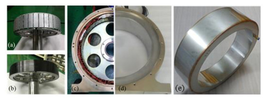
Figure 6.
Fabricated rotors and stators. The full configuration of rotor (a) before CFRP sealing and (b) after CFRP sealing. The half configuration of stator (c) without waterproofing can, (d) with waterproofing can, and (e) waterproofing can configuration.
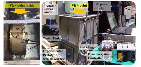
Figure 7.
The experimental prototype in the tank and the test set.
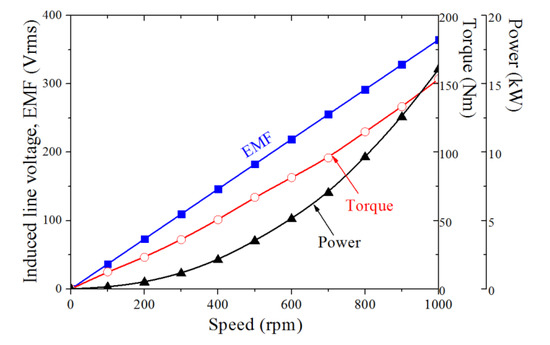
Figure 8.
No-load test results according to speed variation (TEST4).
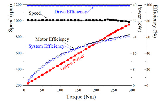
Figure 9.
Load test results according to load torque variation (TEST5).
In order to classify the measured power as effective and loss powers, several times no-load tests were performed under various conditions. The results are listed in Table 5. Torque_m and Power_m denote the directly measured torque and power using torque sensor and power analyzer outside the tank. Power_eff stands for the effective power for work against fluid resistance. The various loss and effective powers are computed in the max speed 1000 rpm as follows:
Table 5.
No-load test results (speed: 1000 rpm).
- (a)
- Mechanical loss: Power_m(TEST1) = 0.7 kW
- (b)
- Waterproofing can loss: Power_m(TEST3) − Power_m (TEST1) = 6.9 kW − 0.7 kW = 6.2 kW
- (c)
- Effective power in TEST4: Power_eff(TEST4) = Power_m (TEST4) − Power_m(TEST3) = 16.1 kW − 6.9 kW = 9.2 kW
The load test shown in Figure 9, TEST5, was performed with the same amount of water as TEST4. Since the power in Figure 9 is the values of load motor power, the Power_eff (TEST4) should be considered for pure output power of the second prototype. Therefore, the maximum pure output power in the max speed 1000 rpm can be calculated as follow: Power_m (TEST5) + Power_eff (TEST4) = 28.4 kW + 9.2 kW = 37.6 kW. The predicted efficiency in Table 4 and the measured efficiency in Figure 9 appear to be very different, 78.5% and 60.3%, respectively. This is the difference due to friction loss and bearing loss due to water in the air gap. The bearing loss is very small, so the effect is negligible. And if the friction caused by water is considered as the load of the motor, the output of the motor generated by overcoming the friction of water becomes the measured power plus 9.2 kW, which is effective power. Accordingly, the efficiency of the motor measured under the same conditions as those in Table 4 is 80.4%. It matches well with the efficiency of the analysis.
The temperature distributed on end-winding was measured by thermocouple. The measurement results of motor with and without waterproofing can in the different fluid tanks are illustrated in Figure 10 and Figure 11. The obtained mechanical loss and effective power from the experiment are applied to the thermal analysis to keep the same condition between thermal simulation and measurement. The comparison of measured and calculated temperature is shown in Table 6. It can be found that the error is under 3% and it can be acceptable.
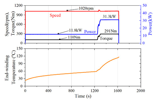
Figure 10.
The measured temperature of first prototype (motor without waterproofing can) in the oil tank.
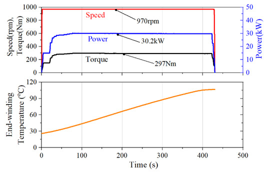
Figure 11.
The measured temperature of the second prototype (motor with waterproofing can) in the water tank.
Table 6.
Comparison of measured and simulated temperature distributed on the end-winding.
5. Conclusions
During the waterproof can design for the stator in the IMP motor, eddy current loss on the can and output power were calculated by 2-D FEA and verified by the test results. At the maximum speed of 1000 rpm, the analytically expected can loss and the output power were 7.4 kW and 39 kW, respectively, while the can loss and output power obtained by measured data were 6.2 kW and 37.6 kW. Considering the limitation of 2-D analysis and possible errors, the difference between analysis and test results is acceptable. Moreover, the temperature distributed on end-winding was successfully verified by both simulation and experiment. This proves the accuracy of the LPTN method in thermal field calculation for electric motors with waterproofing can. We hope this paper helped to establish a fast and reliable motor design process when designing an IMP motor.
Author Contributions
Conceptualization, J.-Y.L.; software, J.-Y.L. and P.T.L.; validation, J.-Y.L.; writing—J.-Y.L. and P.T.L. All authors have read and agreed to the published version of the manuscript.
Funding
This Research was supported by Korea Electrotechnology Research Institute (KERI) Primary Research program through the National Research Council of Science and Technology (NST) funded by the Ministry of Science and ICT (MSIT) (No. 20A01020).
Conflicts of Interest
The authors declare no conflict of interest.
References
- Cheng, B.; Pan, G.; Cao, Y. Analytical design of the integrated motor used in a hubless rim-driven propulsor. IET Electr. Power Appl. 2019, 13, 1255–1262. [Google Scholar] [CrossRef]
- Tuohy, P.M.; Smith, A.C.; Husband, M.; Hopewell, P. Rim-drive marine thruster using a multiple-can induction motor. IET Electr. Power Appl. 2013, 7, 557–565. [Google Scholar] [CrossRef]
- Liang, J.; Zhang, X.; Qiao, M.; Zhu, P.; Cai, W.; Xia, Y.; Li, G. Optimal design and multifield coupling analysis of propelling motor used in a novel integrated motor propeller. IEEE Trans. Magn. 2013, 49, 5742–5748. [Google Scholar] [CrossRef]
- Gieras, J.F. Advancements in Electric Machines. Springer; Available online: https://www.springer.com/gp/book/9781402090066 (accessed on 12 March 2020).
- High Power Density Integrated Electric Drive Propulsor|SBIR.gov. Available online: https://www.sbir.gov/sbirsearch/detail/297533 (accessed on 12 March 2020).
- Batzel, T.D.; Thivierge, D.P.; Lee, K.Y. Application of sensorless electric drive to unmanned undersea vehicle propulsion. IFAC Proc. Vol. 2002, 35, 307–312. [Google Scholar] [CrossRef]
- Lee, J.Y.; Hong, D.K.; Ahn, M.H.; Woo, B.C. Electric motor design of an integrated motor propulsor for unmanned underwater vehicles: The effect of waterproofing can. In Proceedings of the Compumag Conference, Daejeon, Korea, 18–22 June 2017. [Google Scholar]
- Li, Y.; Mao, Z.; Song, B.; Tian, W. Design and analysis of stator modular integrated motor propulsor. In Proceedings of the OCEANS 2017, Aberdeen, Scotland, 19–22 June 2017. [Google Scholar]
- Pan, G.; Cheng, B.; Zhang, P.; Cao, Y. Coupling design and performance analysis of rim-driven integrated motor propulsor. In Proceedings of the OCEANS 2016, Shanghai, China, 10–13 April 2016. [Google Scholar]
- Abu Sharkh, S.M.; Harris, M.R.; Stoll, R.L. Design and performance of an integrated thruster motor. In Proceedings of the 1995 Seventh International Conference on Electrical Machines and Drives (Conf. Publ. No. 412), Durham, UK, 11–13 September 1995; pp. 395–399. [Google Scholar]
- Lee, J.Y.; Woo, B.C.; Kim, D.J.; Hong, D.K.; Ahn, M.H. Electric motor design for propulsor system in unmanned underwater vehicles. In Proceedings of the KIEE Spring conference for Society B, Jeju, Korea, 21–23 March 2016. [Google Scholar]
- Lee, J.Y.; Hong, D.K.; Ahn, M.H.; Woo, B.C. Analysis and experiment of the propulsion motor in unmanned submarine system. Proceeding of the KIEE summer conference, Pyeongchang, Korea, 13–15 July 2016. [Google Scholar]
- Hong, D.K.; Joo, D.S.; Lee, J.Y.; Woo, B.C. Effects of the pole-slot combination on the PMSM of an integrated motor propulsor for an unmanned underwater vehicle considering its electric performance, noise, and vibration. Int. J. Appl. Electromagn. Mech. 2016, 52, 1689–1695. [Google Scholar] [CrossRef]
- Cheng, L.; Tian, G.Y. Surface crack detection for carbon fiber reinforced plastic (CFRP) materials using pulsed eddy current thermography. IEEE Sens. J. 2011, 11, 3261–3268. [Google Scholar] [CrossRef]
- Maxwell Online Help, Ansys Corporation, Maxwell 18.0. Available online: https://www.scribd.com/document/370055766/Ansys-Maxwell-18-Online-Help (accessed on 12 March 2020).
- Nam, H.; Ha, K.-H.; Lee, J.-J.; Hong, J.-P.; Kang, G.-H. A study on iron loss analysis method considering the harmonics of the flux density waveform using iron loss curves tested on Epstein samples. IEEE Trans. Magn. 2003, 39, 1472–1475. [Google Scholar]
- Zhao, N.; Liu, W. Loss calculation and thermal analysis of surface-mounted PM motor and interior PM motor. IEEE Trans. Magn. 2015, 51, 1–4. [Google Scholar]
- Staton, D.A.; Cavagnino, A. Convection heat transfer and flow calculations suitable for electric machines thermal models. IEEE Trans. Ind. Electron. 2008, 55, 3509–3516. [Google Scholar] [CrossRef]
- Kim, K.-C.; Koo, D.-H.; Lee, J. The study on the overhang coefficient for permanent magnet machine by experimental design method. IEEE Trans. Magn. 2007, 43, 2483–2485. [Google Scholar] [CrossRef]
- Yeo, H.-K.; Park, H.-J.; Seo, J.-M.; Jung, S.-Y.; Ro, J.-S.; Jung, H.-K. Electromagnetic and thermal analysis of a surface-mounted permanent-magnet motor with overhang structure. IEEE Trans. Magn. 2017, 53, 1–4. [Google Scholar] [CrossRef]
- Song, J.-Y.; Lee, J.H.; Kim, Y.-J.; Jung, S.-Y. Computational method of effective remanence flux density to consider PM overhang effect for spoke-type PM motor with 2-D analysis using magnetic energy. IEEE Trans. Magn. 2016, 52, 1–4. [Google Scholar] [CrossRef]


© 2020 by the authors. Licensee MDPI, Basel, Switzerland. This article is an open access article distributed under the terms and conditions of the Creative Commons Attribution (CC BY) license (http://creativecommons.org/licenses/by/4.0/).