Abstract
In order to enhance heat transfer in the abrasive-milling processes to reduce thermal damage, the concept of employing oscillating heat pipes (OHPs) in an abrasive-milling tool is proposed. A single-loop OHP (SLOHP) is positioned on the plane parallel to the rotational axis of the tool. In this case, centrifugal accelerations do not segregate the fluid between the evaporator and condenser. The experimental investigation is conducted to study the effects of centrifugal acceleration (0–738 m/s2), heat flux (9100–31,850 W/m2) and working fluids (methanol, acetone and water) on the thermal performance. Results show that the centrifugal acceleration has a positive influence on the thermal performance of the axial-rotating SLOHP when filled with acetone or methanol. As for water, with the increase of centrifugal acceleration, the heat transfer performance first increases and then decreases. The thermal performance enhances for higher heat flux rises for all the fluids. The flow inside the axial-rotating SLOHP is analyzed by a slow-motion visualization supported by the theoretical analysis. Based on the theoretical analysis, the rotation will increase the resistance for the vapor to penetrate through the liquid slugs to form an annular flow, which is verified by the visualization.
1. Introduction
During abrasive-milling processes, a large amount of heat is generated in the contact zone between the abrasive-milling tool and workpiece. Consequently, when abrasive-milling hard-to-machine materials with low heat conduction (e.g., nickel-based superalloy, carbon fiber reinforced composites or ceramic matrix composites), the heat gathers in contact zone and leads to critical hot spots and serious thermal damage for both the workpiece and tool [1,2,3,4]. To solve this problem, the heat should be transferred out through the tool in time to reduce the stored heat, lowering the temperature in the contact zone, with the result decreasing the risk of thermal damage.
Heat pipes are passive heat transfer devices with excellent heat transport capacity. They are widely used in the microelectronics, manufacturing, and automobile and aerospace industries for thermal management. Lately, heat pipes have been applied to the machining process to enhance heat transfer [5,6,7,8,9]. The heat is absorbed by the working fluid in the evaporator of the heat pipe, which, in the case of the tool, is near the contact zone. The phase change occurs, and vapor moves to the condenser to release heat by condensing into liquid. After this, the liquid returns to the evaporator either by capillary wick or unbalanced pressure distribution. In the case of applying heat pipes in the cutting tools, such fluid motion continues to transfer out the heat, with high heat transport capacity during the machining processes. The combination of heat pipes and cutting tools was conducted by several researchers [5,6,7], and the heat pipe cutting tool shows a great advantage in enhancing the heat and cooling the tool in the processes. He et al. [8,9] and Chen et al. [10,11] designed and produced axial-rotating and radial-rotating heat pipe grinding wheels. A titanium alloy and nickel-based superalloy were successfully dry-grinded by heat pipe grinding wheels without grinding burnout. An in-depth numerical analysis was conducted, where results show that the wickless heat pipe can assist heat transfer under a low rotational speed. Nucleate boiling was found to be totally suppressed while increasing the centrifugal acceleration. Laminar convection heat transfer is the heat transfer mode in the evaporator when the centrifugal acceleration is more than 1000 times the gravity acceleration.
The oscillating heat pipe (OHP, also called the pulsating heat pipe) is a novel heat transfer device, which has been developed since the 1990s. It is made of a meandering capillary tube which is partially filled with working fluid [12]. In recent years, experimental and theoretical research has been carried out on the thermal performance of OHPs and their heat transfer mechanism. The heat transport capacity of OHPs is affected by geometric, physical and operational parameters, such as inner diameters, working fluid properties, filling ratio, etc. It was found that within the critical inner diameter, an OHP with a larger inner diameter has a better heat transfer capability [13]. The influence of the working fluid on the heat transport capacity of the OHP has been described by several researchers [14,15]. The thermal performance of an OHP is also determined by its flow regimes, which in turn are affected by the working fluids. In general, fluids with lower dynamic viscosity and smaller surface tension lead to better performance, due to their lower friction and the higher wettability, which lead to a higher response to the pressure variation and the presence of a liquid film on the wall (decreasing the probability of dry spot occurrence). Fluids with a lower latent heat (such as acetone) bring powerful oscillations into the OHP, while they have a higher possibility of dry-out. OHPs charged with fluids with higher latent heat (e.g., water) may have better heat transfer performance in terms of maximum heat flux, but the start-up power is higher. The influence of operational parameters on the heat transfer was investigated by some researchers, such as Stevens et al. [16]. Operational parameters, which include a filling ratio (FR), inclination angle and heat load, etc., have significant effects on the heat transfer. In most of the experiments, there exists an optimized filling ratio which is within 40% to 60%, and the OHP will have a better heat transfer ability under the inclination of 50° to 90° for the proposed four turns closed-loop OHP [13,14,17,18]. Below the maximum heat flux, increasing the heat load, the flow regime develops from a bubbly flow to a slug flow to a transient flow, and then to an annular flow. As a result, the heat transfer performance varies depending on the flow patterns [19,20].
Due to the high heat transfer capability and the simple wickless structure, OHPs have the potential for application in the machining process for the enhancement of heat transfer. The OHP cutting tool was first proposed by Wu et al. [21,22]. A Ti-6Al-4V alloy was dry-cut by an OHP cutting tool. Compared with conventional cutting tools, the cutting tool with the OHP reduced the process temperature, and the tool wear-rate became slower by 20%. As for the grinding process, Qian et al. [19] introduced the concept of the OHP grinding wheel. The heat transfer analysis was studied to the point of the proof of concept. The heat transfer prediction model was built, and the start-up performance was also analyzed [23,24].
In order to dissipate the heat generated in the contact zone during the abrasive-milling of hard-to-machine materials, the concept of combining the OHP with the abrasive-milling tool is proposed, as illustrated in Figure 1. Several single-loop OHPs are formed by the independent channels machined in the tool matrix. The generated heat in the contact zone is transferred into the evaporator through the abrasive layers, and is then brought to the condenser to transfer out.
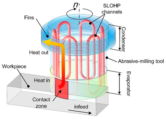
Figure 1.
Illustration of an OHP abrasive-milling tool.
In this case, a rotation is involved. Experimental investigations of the heat transfer and flow patterns of “flower-shaped” radial-rotating OHPs were conducted by Aboutalebi et al. [25], Ebrahimi et al. [26], Liou et al. [27] and On-ai et al. [28]. In their studies, the maximum rotational speed reached 800 revolutions per minute (rpm), and the maximum centrifugal acceleration reached around 20 times gravity acceleration. For such a range of rotational speed and centrifugal acceleration, they all found that employing rotational speed was a way to enhance the internal flow, and the centrifugal acceleration has a positive influence on the increase of thermal performance. These oscillating heat pipes rotate around the central axis of the tool with the condenser at the centre and the evaporator at the external side. In this case, centrifugal accelerations segregate the fluid between the evaporator and condenser, pushing the fluid to the evaporator.
In our case, the OHP, whose central axis is aligned to the rotational axis of the tool, is positioned on the plane parallel to the rotational axis of the tool. In this case, centrifugal accelerations do not segregate the fluid between the evaporator and condenser. To the best of our knowledge, there is no previous paper on the influence of rotation on such positioning of OHPs, especially for a single-loop OHP.
In this paper, experiments are conducted to investigate the effects of centrifugal acceleration, heat flux and working fluids on the thermal performance of OHPs under axial-rotating conditions. The flow of liquid slugs and vapor plugs inside the axial-rotating SLOHP is also analyzed by the theoretical method. Moreover, the flow is also observed through a slow-motion camera.
2. Experimental Preparation and Data Processing
2.1. Description of Experimental Apparatus
The oscillating heat pipe (OHP) abrasive-milling tool (OHP tool) comprises several axial-rotating single-loop oscillating heat pipes (SLOHPs). For simplification, in this paper, one axial-rotating SLOHP is designed and made for the experiment, as shown in Figure 2. The axial-rotating OHP includes a holder, a copper SLOHP, a slip ring, thermocouples and Ni-Cr heating wires. The SLOHP is mounted on the holder 30 mm away from its rotational axis, which is the same as the radius of the OHP tool. The outer and inner diameters of a SLOHP are 5 mm and 3 mm, respectively. The evaporator, adiabatic section and condenser are 30 mm, 40 mm and 30 mm long, respectively. The SLOHP is evacuated to the pressure of 10−2 Pa, and then filled with acetone (CH3COCH3), methanol (CH3OH) or deionized water (DI water) as working fluids, with a filling ratio of 55%, through the vacuum and injection tube. The axial-rotating SLOHP is bottom-heated by a Ni-Cr wire, which is connected to the KIKUSUI PZB40-10 power supply (limits of error: ±0.1 W) through the slip ring and copper brush. The axial-rotating SLOHP is wrapped with an aerogel insulation to avoid heat leak. The condenser is cooled by the 0.4 MPa cold air jet at a temperature under 5 °C. Temperatures of the evaporator and condenser are measured by Omega type-K thermocouples (limits of error: 0.4%). Signals are transferred through the slip ring and copper brush to the NI-USB 6366 card under the sampling rate of 10 Hz, and signals are processed by NI LabView and NI DIAdem software (National Instruments, Shanghai, China). The environment temperature is maintained at 25±1° C. The setup of the experiment is illustrated in Figure 2.
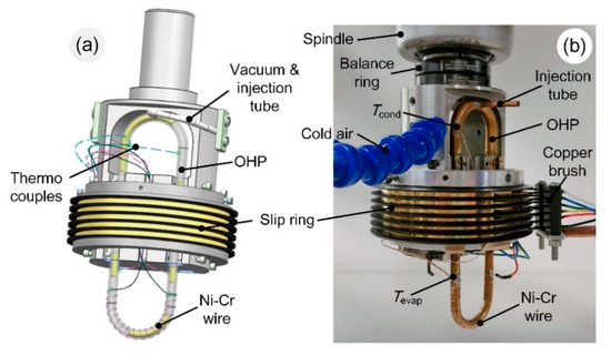
Figure 2.
Experimental preparation of axial-rotating oscillating heat pipe: (a) illustration of axial-rotating OHP; and (b) experimental setup (aerogel insulation was removed for better illustration).
In the abrasive-milling process, the rotational speed of the tool varies from several hundred to a thousand rpm, and the effective heat flux generated in the contact zone is around 105 W/m2. In this case, in order to study the thermal performance of the axial-rotating SLOHP under the same conditions with the abrasive-milling process, the rotational speeds in the experiment are 0, 300, 950, and 1500 rpm, with a relative centrifugal acceleration of 0, 30, 296, and 738 m/s2. The heat flux used in the experiment varies from 9100 W/m2 to 31,850 W/m2, with an increment of 4550 W/m2. The detailed conditions are shown in Table 1.

Table 1.
Experimental conditions.
The thermophysical properties of working fluids (i.e., methanol, acetone and DI water) are shown in Table 2.
Table 2.
Physical properties of working fluids at 1 atm.
2.2. Data Processing
Thermal resistance is used as the measurement of the thermal performance of the axial-rotating SLOHP. The thermal resistant is defined as follows
where Q is the heat load, and Tevap and Tcond are the time-averaged temperatures in evaporator and condenser. Lower thermal resistance means a better thermal performance of the axial-rotating SLOHP. The uncertainty of the thermal resistance is evaluated based on the method in [19]. The uncertainty is less than 5%.
3. Flow Visualization and Modeling
3.1. Flow Inside Axial-Rotating Single-Loop Oscillating Heat Pipe (SLOHP) Under Rotation
A glass axial-rotating SLOHP is made for visualization. The flow of working fluid inside the axial-rotating SLOHP is captured by a portable camera at a 240-frames-per-second speed (eight times slower). Due to the limitation of the apparatus and in the light of safety, the rotational speed is set up to 300 rpm in this case.
Under the static state and heat flux of 22,750 W/m2, the flow pattern of the working fluid, acetone, is a veering circulation with an annular flow and slug flow. When the vapor bubbles and plugs generate, expand and move up to the condenser, the vapor easily penetrates the liquid slugs to form the annular flow (see Figure 3a(i–iii)), while the flow in the neighboring tube remains a train of liquid slugs and vapor plugs (see Figure 3a(ii,iii)). Besides, the direction of circulation changes from time to time, as shown in Figure 3a(ii,iii).
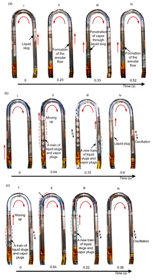
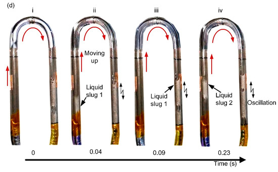
Figure 3.
Flow inside the axial-rotating SLOHP filled with acetone under 22,750 W/m2: (a) at static state; (b) at 60 rpm rotating speed; (c) at 150 rpm rotating speed; and (d) at 300 rpm rotating speed.
When the axial-rotation is applied, as mentioned in the theoretical analysis in Section 3.2, the resistance for the vapor to penetrate the liquid slug becomes larger, and as a result it is more difficult for the vapor to penetrate through the liquid slug to form the annular flow. The flows inside the axial-rotating SLOHP at the speeds of 60, 150 and 300 rpm are shown in Figure 3b–d. At the rotating speed of 60 rpm, the flow is a veering slug flow, which generates a train of liquid slugs and vapor plugs (see Figure 3b(ii)). Sometimes, when a train of liquid slugs and vapor plugs moves from evaporator to condenser, it will slow down and stop, and a new train of liquid slugs and vapor plugs is generated in the neighboring tube and moves upwards, causing the flow direction to change (see Figure 3b(ii,iii)). The whole process is illustrated in Figure 3b. At the rotating speeds of 150 and 300 rpm, the unidirectional circulation forms. Since the SLOHP rotates clockwise, the inertia causes the working fluid to flow in a one-way, clockwise direction inside the SLOHP. In this case, liquid slugs generate and move up to the condenser in the left tube, while in the right tube, liquid slugs and vapor plugs oscillate at the adiabatic section (see Figure 3c(i,iii) and Figure 3d(ii,iv)). Though flows at rotational speeds of 150 rpm and 300 rpm are similar, new trains of liquid slugs and vapor plugs are generated at the speed of 150 rpm (Figure 3c(i,iii)), while just one liquid slug forms and moves up at a time at the speed of 300 rpm (Figure 3d(ii,iv)).
As mentioned before, under the static state, vapor easily penetrates through the liquid slugs to form an annular flow. Under axial-rotation, especially when the speed exceeds 150 rpm, unidirectional circulation forms. It takes a relatively long time to form a long train of liquid slugs and vapor plugs at the speed of 150 rpm. Nevertheless, one short liquid slug is generated at a shorter time at the speed of 300 rpm, as shown in Figure 4.
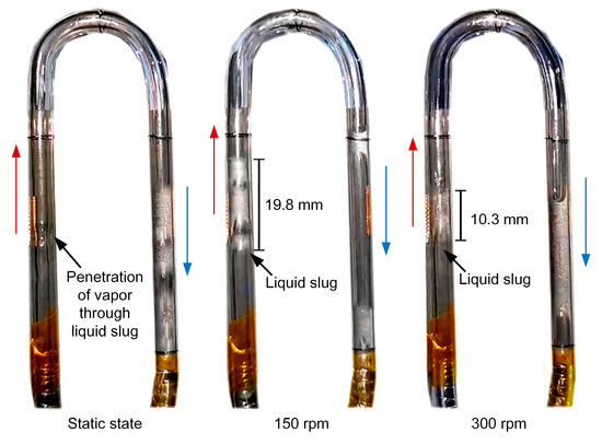
Figure 4.
Comparison of liquid slug lengths under different rotating speeds (heat flux of 22,750 W/m2).
3.2. Modelling of Flow Under Rotation
For a well-working oscillating heat pipe (OHP), a train of liquid slugs and vapor plugs must form and exist in the system. At the moment that the evaporator is heated, the liquid turns into vapor, causing the expansion of the vapor volume. When the vapor velocity exceeds some critical value, the vapor plug penetrates all liquid plugs and generates an annular flow. At this moment, the mass-spring system, consisting of a train of liquid slugs and vapor plugs, vanishes. The oscillating motion stops, and the OHP reaches the highest heat transport capacity [29]. The illustration of the flow inside the OHP is shown in Figure 5.
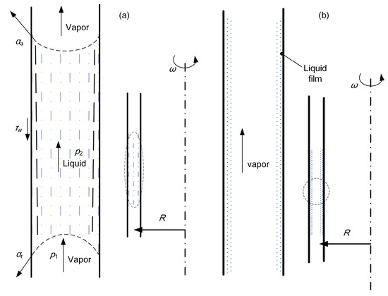
Figure 5.
Illustration of liquid slug moving in the OHP: (a) right before the vapor penetrating through the liquid slug; and (b) right after the penetration of vapor through the liquid slug.
When the vapor penetrates the liquid slug, the momentum that is generated by the vapor plugs will be used to overcome the total forces applying on the liquid plug, i.e.,
where ρv is the vapor density, p1 and p2 are the vapor pressure, r0 is the radius of the tube, σ is the surface tension, αa and αr are the advancing and receding contact angles and τw is the shear stress. The left term is the momentum produced by the vapor due to the vapor volume expansion. The right of the equation is marked as the total resistant force. The first term of the right part is the pressure differences acting on the liquid slug and vapor plug, while the second term of the right part is due to the surface tensions and the last term is due to the shear stress between the wall and fluid.
The pressure of vapor and liquid are
where p0,v and p0,l are the pressure of the vapor and liquid phases under a static state, R is the distance between the OHP and the rotational axis and ω is the angular velocity.
The shear stress on the wall can be expressed as:
According to the solution proposed by Ma [29], Equation (1) can be solved as follows
where ul,max is the maximum velocity of the liquid phase and μl is the dynamic viscosity of the liquid.
The following parameters are defined as follows:
Therefore, Equation (6) will be rewritten as:
Under the static state, the driving force of vapor and the total resistant force to overcome are:
Meanwhile, under the axial-rotating condition, the driving force of vapor and the total resistant force to overcome is shown in Equation (10). It is clear that total resistant force is increased in case of an axial-rotating condition by , so the vapor plug is more difficult to penetrate the liquid slug under axial rotation, and the annular flow will turn into slug flow under axial-rotation.
4. Results and Discussion
4.1. Effects of the Centrifugal Acceleration
The influence of rotation is described through the rotational speed and radius. Figure 6 illustrates the effects of centrifugal acceleration on the thermal performance of the axial-rotating single-loop oscillating heat pipe (SLOHP) filled with methanol, acetone and deionized water (DI water). It is clear that the centrifugal acceleration has a positive influence on the heat transport capacity of the axial-rotating SLOHP filled with methanol and acetone. When the centrifugal acceleration increases up to 30 m/s2, the thermal resistance decreases rapidly for all the fluids. In the range of the centrifugal acceleration from 30 m/s2 to 738 m/s2, the thermal performance enhances for most cases of the axial-rotating SLOHP filled with methanol and acetone. In the range of 0 m/s2 to 738 m/s2, the thermal resistance decreases by 22% and 137% for the axial-rotating SLOHP filled with methanol and acetone, respectively. According to previous studies [19,25,28,30], the inside flow patterns can be estimated through the temperature curves. In the evaporator, the longer the vapor plug is, the longer it passes through the temperature measuring point, and the slower the vapor moves, the longer it passes through the measuring point. This leads to a higher amplitude of the temperature, as the hot long vapor plug will increase the temperature of the damped measuring point gradually until a liquid slug passes the measuring point (see Section 3.1). Moreover, the temperature differences decrease when the fluid circulation is faster and the vapor plugs and liquid slugs become shorter.
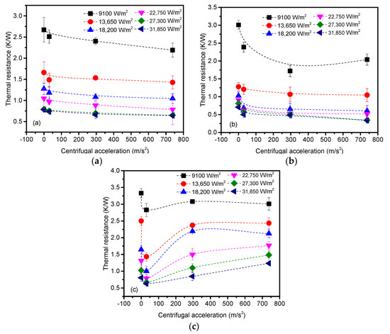
Figure 6.
Effects of centrifugal acceleration: (a) methanol; (b) acetone; and (c) DI water.
In order to emphasize the influence of the centrifugal acceleration on the flow pattern, a rotational speed of 950 rpm (296 m/s2) is applied on the SLOHP filled with methanol under the heat flux of 27,300 W/m2. Figure 7a shows the evaporator temperature curve. Under static conditions (a = 0 m/s2), the value of the evaporator temperature is high, with the peak-to-valley value being around 20 °C, and the evaporator temperature fluctuating at low frequencies. On the contrary, under the centrifugal acceleration of 296 m/s2, the temperature curve is obviously smoother, with a smaller amplitude and high oscillation frequencies. The peak-to-valley amplitude is around 10 °C under these conditions. In terms of the methanol and acetone, the centrifugal acceleration likely changes the annular flow to slug flow, as it is qualitatively proven by the theoretical analysis in Section 3.2, and increases the circular motion velocity. As a result, for methanol and acetone as working fluids, the thermal performance of the axial-rotating SLOHP enhances with the increase of centrifugal acceleration.
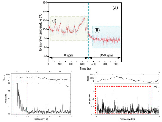
Figure 7.
Evaporator temperature under rotational speed of 0 rpm and 950 rpm (filled with methanol): (a) temperature curve; and (b) and (c) FFT analysis of the temperature curve in areas (I) and (II).
On the contrary, as shown in Figure 6c, a different behavior is observed when DI water is the working fluid. Up to a = 30 m/s2, the heat transfer performance increases sharply, the thermal resistance drops by up to 74%, from 2.5 K/W to 1.43 K/W, under the heat flux of 13,650 W/m2. As the centrifugal acceleration exceeds 30 m/s2, the thermal resistance rises gradually, which means the thermal performance deteriorates. Specifically, when the centrifugal acceleration is higher than 296 m/s2, the thermal performance is lower than that of the static state at the heat flux range from 18,200 W/m2 to 31,850 W/m2. Therefore, in terms of the axial-rotating SLOHP filled with DI water, the thermal performance first enhances and then decreases along with the increase of centrifugal acceleration, which peaks at 30 m/s2. This result is consistent with previous studies [22,25]. The reasons for such different behavior of water can be found in its higher viscosity (Table 2), which increases the flow friction [28], the higher thermal conductivity, which can produce local transient dry-out [25], and the lower value of (dp/dT)sat, which brings it to a weaker expansion, i.e. a weaker flow circulation (see also Section 3.1). From the visualization, it is observed that under 300 rpm, the flow of water is a discontinuous train of vapor bubble and liquid slug. Meanwhile, when the speed exceeds 300 rpm, it is difficult to form effective circulation. An intermittent train of bubble and slug forms, and sometimes moves to the condenser. Most of the time, no obvious motion is observed—just local oscillation.
4.2. Effects of the Heat Flux
When the heat flux increases from 9100 W/m2 to 31,850 W/m2, the thermal performance of the axial-rotating SLOHP enhances at all centrifugal accelerations for all working fluids (Figure 8). In detail, for the axial-rotating SLOHP filled with methanol, the thermal resistance decreases from around 2.67 K/W to around 0.64 K/W by up to 4.5 times. As for the acetone as the working fluid, the thermal resistance decreases from around 3.01 K/W to around 0.34 K/W by a maximum of 8.6 times. Similarly, in terms of DI water, the thermal resistance decreases from around 3.33 K/W to around 0.63 K/W by four times. Based on our previous research [19], as the heat flux increased, changes of flow pattern and motion modes—which develops from bubbly flow to vapor plug flow, then to annular flow, and from oscillation to circulation—enhance the OHP’s thermal performance.
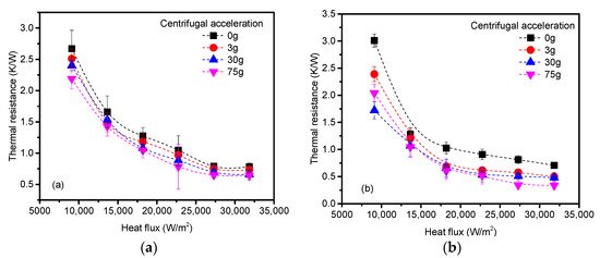
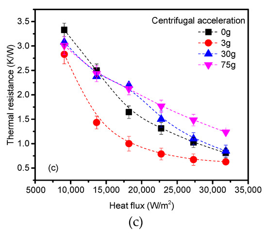
Figure 8.
Effects of heat flux: (a) methanol; (b) acetone; and (c) DI water.
4.3. Effects of the Working Fluid
From Table 2, acetone and methanol have a high (dp/dT)sat value, low dynamic viscosity and low surface tension, which lead to a higher driving force and the lower resistance of flow motion. On the other hand, DI water has a higher thermal conductivity, latent heat and specific heat. Due to differences in thermophysical properties, the working fluid has an important impact on thermal performance under the axial-rotating condition. The influence of the working fluids is different under low and high centrifugal accelerations, as illustrated in Figure 9. The axial-rotating SLOHP filled with acetone has the highest heat transport capacity, regardless of the heat flux and centrifugal acceleration. At the low centrifugal acceleration (e.g., 30 m/s2), the effective heat transfer coefficient of the axial-rotating SLOHP filled with DI water is higher than that of methanol in general. However, when the centrifugal acceleration is high (e.g., 738 m/s2), the thermal performance of the axial-rotating SLOHP filled with methanol is better than that of DI water. This is due to different flow patterns and motion modes, which are caused by the differences of thermophysical properties at varied centrifugal accelerations. In the light of this—for the given temperatures and heat load ranges, and even if the deeper reasons are not completely clear—as a conclusion, acetone is the recommended working fluid for this axial-rotating SLOHP, which is supposed to work in the abrasive-milling tool to enhance heat transfer in abrasive-milling processes.
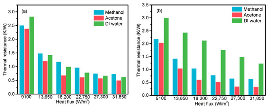
Figure 9.
Effects of working fluids under centrifugal acceleration of: (a) 30 m/s2; and (b) 738 m/s2.
5. Conclusions
The influences of centrifugal acceleration, heat flux and working fluid on the thermal performance of the axial-rotating SLOHP are investigated through visualization, theoretical analysis and experiments. The main conclusions are drawn as follows:
The flow inside axial-rotating SLOHP is analyzed through the theoretical and visualization method. Based on theoretical analysis, the rotation will increase the resistance for the vapor to penetrate through the liquid slugs to form an annular flow, which is verified by the visualization. Besides, under the static state and heat flux of 22,750 W/m2, the flow pattern of working fluid, acetone, is a veering circulation with the annular flow and slug flow. Meanwhile, under the axial-rotating conditions, the flow turns into slug flow. When the rotating speed increases from 60 rpm to 300 rpm, the flow changes from veering circulation to unidirectional circulation, and the liquid slug becomes shorter with a higher generating frequency.
For the acetone and methanol as working fluids, the thermal performance is enhanced by increasing the centrifugal acceleration, which is demonstrated through the change of internal flow motions. Nevertheless, the thermal performance of the axial-rotating SLOHP filled with DI water enhances first, and then decreases when the centrifugal acceleration increases. The acetone is recommended since the axial-rotating SLOHP filled with acetone has the best thermal performance. Furthermore, the heat transport capacity of the axial-rotating SLOHP improves with the increase of heat flux for all cases.
Author Contributions
Conceptualization, N.Q., Y.F. and J.X.; methodology and analysis, N.Q., M.M. and F.J.; writing—original draft preparation, N.Q., J.C.; writing—review and editing, Y.F., M.M. and J.X.; supervision, Y.F., M.M. and J.X.; funding acquisition, Y.F., M.M. and J.C. All authors have read and agreed to the published version of the manuscript.
Funding
The authors gratefully acknowledge the financial support for this work by the National Natural Science Foundation of China (Grant Nos. 51175254 and 51905275), National Natural Science Foundation of China for Creative Research Group (Grant No. 51921003) and Natural Science Foundation of Jiangsu Province (Grant No. BK20190752). Marco Marengo has been supported by UK EPSRC through the grant EP/P013112/1 (HyHP project, https://blogs.brighton.ac.uk/hyhp/).
Acknowledgments
The authors would like to address a great thank to Jiusheng Xu for his assistant to build the apparatus.
Conflicts of Interest
The authors declare no conflict of interest.
Nomenclature
| a | Centrifugal acceleration, m/s2 |
| g | Gravity acceleration, 9.8 m/s2 |
| heff | Effective heat transfer coefficient, W/m2∙K |
| p | Pressure, Pa |
| Q | Heating power, W |
| q" | Heat flux, W/m2 |
| R | Thermal resistance, K/W (°C /W); distance from the rotational axis to the SLOHP, m |
| r0 | Radius of SLOHP tube, m |
| T | Temperature, °C |
| u | Velocity, m/s |
| Greek | |
| α | Contact angle, o |
| μ | Dynamic viscosity, N∙s/m2 |
| ρ | Density, kg/m3 |
| τ | Shear stress, N/m2 |
| ω | Angular velocity of rotation, rad/s |
| Subscripts | |
| a | Advancing |
| cond | Condenser |
| eff | Effective |
| evap | Evaporator |
| l | Liquid |
| max | Maximum |
| sat | Saturated |
| r | Receding |
| v | Vapor |
| w | Wall |
| 1 | Vapor phase |
| 2 | Liquid phase |
References
- Qian, N.; Ding, W.; Zhu, Y. Comparative investigation on grindability of K4125 and Inconel718 nickel-based superalloys. Int. J. Adv. Manuf. Technol. 2018, 97, 1649–1661. [Google Scholar] [CrossRef]
- Gavalda Diaz, O.; Garcia Luna, G.; Liao, Z.; Axinte, D. The new challenges of machining Ceramic Matrix Composites (CMCs): Review of surface integrity. Int. J. Mach. Tools Manuf. 2019, 139, 24–36. [Google Scholar] [CrossRef]
- Liang, Y.; Chen, Y.; Chen, B.; Fan, B.; Yan, C.; Fu, Y. Feasibility of Ultrasonic Vibration Assisted Grinding for Carbon Fiber Reinforced Polymer with Monolayer Brazed Grinding Tools. Int. J. Precis. Eng. Manuf. 2019, 20, 1083–1094. [Google Scholar] [CrossRef]
- Wang, Y.; Su, H.; Dai, J.; Yang, S. A novel finite element method for the wear analysis of cemented carbide tool during high speed cutting Ti6Al4V process. Int. J. Adv. Manuf. Technol. 2019, 2795–2807. [Google Scholar] [CrossRef]
- Jen, T.; Gutiérrez, G.; Eapen, S.; Barber, G.; Zhao, H.; Szuba, P.; Labataille, J.; Manjunathaiah, J. Investigation of heat pipe cooling in drilling applications. Int. J. Mach. Tools Manuf. 2002, 42, 643–652. [Google Scholar] [CrossRef]
- Robinson Gnanadurai, R.; Varadarajan, A.S. Investigation on the effect of cooling of the tool using heat pipe during hard turning with minimal fluid application. Eng. Sci. Technol. an Int. J. 2016, 19, 1190–1198. [Google Scholar] [CrossRef][Green Version]
- Chiou, R.Y.; Chen, J.S.J.; Lu, L.; North, M.T. The Effect of an Embedded Heat Pipe in a Cutting Tool on Temperature and Wear. Advances in Bioengineering 2003, 369–376. [Google Scholar]
- He, Q.; Fu, Y.; Chen, J.; Zhang, W.; Cui, Z. Experimental investigation of cooling characteristics in wet grinding using heat pipe grinding wheel. Int. J. Adv. Manuf. Technol. 2018, 97, 621–627. [Google Scholar] [CrossRef]
- He, Q.; Fu, Y.; Chen, J.; Zhang, W. Investigation on Heat Transfer Performance of Heat Pipe Grinding Wheel in Dry Grinding. J. Manuf. Sci. Eng. 2016, 138, 111009. [Google Scholar] [CrossRef]
- Chen, J.; Fu, Y.; He, Q.; Shen, H.; Ching, C.Y.; Ewing, D. Environmentally friendly machining with a revolving heat pipe grinding wheel. Appl. Therm. Eng. 2016, 107, 719–727. [Google Scholar] [CrossRef]
- Chen, J.; Fu, Y.; Gu, Z.; Shen, H.; He, Q. Study on heat transfer of a rotating heat pipe cooling system in dry abrasive-milling. Appl. Therm. Eng. 2017, 115, 736–743. [Google Scholar] [CrossRef]
- Bastakoti, D.; Zhang, H.; Li, D.; Cai, W.; Li, F. An overview on the developing trend of pulsating heat pipe and its performance. Appl. Therm. Eng. 2018, 141, 305–332. [Google Scholar] [CrossRef]
- Zhang, Y.; Faghri, A. Advances and unsolved issues in pulsating heat pipes. Heat Transf. Eng. 2008, 29, 20–44. [Google Scholar] [CrossRef]
- Taft, B.S.; Williams, A.D.; Drolen, B.L. Review of Pulsating Heat Pipe Working Fluid Selection. J. Thermophys. Heat Transf. 2012, 26, 651–656. [Google Scholar] [CrossRef]
- Alhuyi Nazari, M.; Ahmadi, M.H.; Ghasempour, R.; Shafii, M.B. How to improve the thermal performance of pulsating heat pipes: A review on working fluid. Renew. Sustain. Energy Rev. 2018, 91, 630–638. [Google Scholar] [CrossRef]
- Stevens, K.A.; Smith, S.M.; Taft, B.S. Variation in oscillating heat pipe performance. Appl. Therm. Eng. 2019, 149, 987–995. [Google Scholar] [CrossRef]
- Saha, N.; Das, P.K.; Sharma, P.K. Influence of process variables on the hydrodynamics and performance of a single loop pulsating heat pipe. Int. J. Heat Mass Transf. 2014, 74, 238–250. [Google Scholar] [CrossRef]
- Mameli, M.; Manno, V.; Filippeschi, S.; Marengo, M. Thermal instability of a Closed Loop Pulsating Heat Pipe: Combined effect of orientation and filling ratio. Exp. Therm. Fluid Sci. 2014, 59, 222–229. [Google Scholar] [CrossRef]
- Qian, N.; Fu, Y.; Zhang, Y.; Chen, J.; Xu, J. Experimental investigation of thermal performance of the oscillating heat pipe for the grinding wheel. Int. J. Heat Mass Transf. 2019, 136, 911–923. [Google Scholar] [CrossRef]
- Khandekar, S.; Gautam, A.P.; Sharma, P.K. Multiple quasi-steady states in a closed loop pulsating heat pipe. Int. J. Therm. Sci. 2009, 48, 535–546. [Google Scholar] [CrossRef]
- Wu, Z.; Deng, J.; Su, C.; Luo, C.; Xia, D. Performance of the micro-texture self-lubricating and pulsating heat pipe self-cooling tools in dry cutting process. Int. J. Refract. Met. Hard Mater. 2014, 45, 238–248. [Google Scholar] [CrossRef]
- Wu, Z.; Yang, Y.; Luo, C. Design, fabrication and dry cutting performance of pulsating heat pipe self-cooling tools. J. Clean. Prod. 2016, 124, 276–282. [Google Scholar] [CrossRef]
- Qian, N.; Fu, Y.; Marengo, M.; Chen, J.; Xu, J. Start-up timing behavior of single-loop oscillating heat pipes based on the second-order dynamic model. Int. J. Heat Mass Transf. 2020, 147, 118994. [Google Scholar] [CrossRef]
- Qian, N.; Wang, X.; Fu, Y.; Zhao, Z.; Xu, J.; Chen, J. Predicting heat transfer of oscillating heat pipes for machining processes based on extreme gradient boosting algorithm. Appl. Therm. Eng. 2020, 164, 114521. [Google Scholar] [CrossRef]
- Aboutalebi, M.; Nikravan Moghaddam, A.M.; Mohammadi, N.; Shafii, M.B. Experimental investigation on performance of a rotating closed loop pulsating heat pipe. Int. Commun. Heat Mass Transf. 2013, 45, 137–145. [Google Scholar] [CrossRef]
- Ebrahimi Dehshali, M.; Nazari, M.A.; Shafii, M.B. Thermal performance of rotating closed-loop pulsating heat pipes: Experimental investigation and semi-empirical correlation. Int. J. Therm. Sci. 2018, 123, 14–26. [Google Scholar] [CrossRef]
- Liou, T.-M.; Chang, S.W.; Cai, W.L.; Lan, I.-A. Thermal fluid characteristics of pulsating heat pipe in radially rotating thin pad. Int. J. Heat Mass Transf. 2019, 131, 273–290. [Google Scholar] [CrossRef]
- On-ai, K.; Kammuang-lue, N.; Terdtoon, P.; Sakulchangsatjatai, P. Implied physical phenomena of rotating closed-loop pulsating heat pipe from working fluid temperature. Appl. Therm. Eng. 2019, 148, 1303–1309. [Google Scholar] [CrossRef]
- Ma, H. Oscillating heat pipes; Springer: New York, NY, USA, 2015; p. 427. ISBN 9781493925049. [Google Scholar]
- Monroe, J.G.; Aspin, Z.S.; Fairley, J.D.; Thompson, S.M. Analysis and comparison of internal and external temperature measurements of a tubular oscillating heat pipe. Exp. Therm. Fluid Sci. 2017, 84, 165–178. [Google Scholar] [CrossRef]


© 2020 by the authors. Licensee MDPI, Basel, Switzerland. This article is an open access article distributed under the terms and conditions of the Creative Commons Attribution (CC BY) license (http://creativecommons.org/licenses/by/4.0/).