Article

A Study on Developing an Automatic Controller with an Inverter Collector Pump for Solar-Assisted Heating System

1
Department of Thermal Engineering, Ho Chi Minh City University of Technology and Education, Ho Chi Minh City 700000, Vietnam
2
Department of Mechanical Engineering, Jeju National University, Jeju, Jeju-do 63243, Korea
*
Author to whom correspondence should be addressed.
Energies 2020, 13(9), 2128; https://doi.org/10.3390/en13092128
Submission received: 11 March 2020 / Revised: 3 April 2020 / Accepted: 9 April 2020 / Published: 27 April 2020

Abstract

:
In this study, based on the optimal equation m = 0.05 Δ T A c (kg/min) of the variable mass flow rate in the collector loop, an automatic controller with an inverter collector pump for the collector loop of the solar-assisted heating system is designed for these experiments and to then be used for real industry. The pump for the collector loop is an inverter type that is controlled by an embedded controller with Windows, based on C# language, and the change of speed depends on the variation of the mass flow rate through the collector loop. The input of the automatic controller with an inverter collector pump is given by a thermocouple input module that is connected to the embedded controller with the RS-485 communication protocol. In this work, the experiments were carried out on three different days, namely a clear day, an intermittently cloudy day and an overcast day, to evaluate the stability and the precision of the automatic controller, as well as the contribution of the useful heat gain from the collector for the solar-assisted heating system. Simulation and experimental results are also validated and analyzed.

1. Introduction

The growth of the population and economy in recent years has led to a rapid increase in energy demand and exacerbated the problem of environmental pollution from CO2 emissions. Recently, most of the research in this field has focused on improving the performance of solar thermal systems to reduce initial investment costs and the energy consumption of the auxiliary heater or auxiliary boilers of this system [1,2]. Hosseinirad et al. [3] proposed an optimal control for a combined heat pump. Badescu [4] investigated the optimal flow rate through the closed loop of the solar domestic hot water system. The optimal flow rate of 0.2 kg/s was determined based on the objective function of Pontryagin’s principle. Several control methods for the collector loop were considered, such as the control problem [5,6,7] and on-off control [8]. In this work, the authors just focused on the effect of the settings on the controller for a solar domestic hot water system.
The magnitude of flow rate in the closed loop was determined based on the relationship of the collector area with the hot water temperature of the collector and storage tank [9]. Ardehali et al. [10] presented a new proportional-sum-derivative (PSD) control methodology; the authors recommended that the new PSD controller must be considered for installation in new heating/cooling systems. Pichler et al. [11] proposed a linear predictive control approach for an auxiliary energy supply to improve collection of solar energy and minimize auxiliary heat demand on the solar-assisted heating systems for a single-family house. Bujedo et al. [12] presented the application of different control strategies in a solar air-conditioning system at part load. The operation of the collector pump depends on the intensity of the solar radiation coming to the surface of the solar collector. Flow rate optimization in a loop of forced circulation solar water heating systems with pipes was proposed by [13].
The effects of the flow distribution through the absorber tubes on the thermal performance of flat-plate solar collectors with riser and header arrangements were presented by [14]. Improvement to the overall efficiency of heat pipe solar water heating based on a novel variable mass flow rate technique which regulates the solar working fluid mass flow rate of the system with the solar radiation intensity also was mentioned by [15,16]. As the above papers were analyzed, the optimal control of flow rate of the collector loop is an indirect function of the input parameters such as solar radiation and temperature; therefore, these investigated results are not applicable to fabricate the controller and not suitable for technical application. In this work, based on the optimal equation m = 0.05 Δ T A c (kg/min) of the solar-assisted heating system given by [17], an automatic controller with an inverter collector pump for the collector loop of the solar-assisted heating system is designed and manufactured to use for experiments on three different days, namely a clear day, an intermittently cloudy day and an overcast day, to evaluate its stability and efficacy, so that it can then be applied to industry.

2. Materials and Methods

2.1. Description of the Solar-Assisted Heating System

Figure 1 shows the schematic diagram of the solar-assisted heating system that is installed on the rooftop of a house on Jeju Island. This system mainly consists of a thermal storage tank, panels for heating, evacuated tube collectors, an oil boiler and a control box. The total surface area (Ac) of evacuated tube collectors is 26 m2, and these collector panels are installed in parallel, facing south. The oil boiler is used as an auxiliary heat source which only provides auxiliary energy for the thermal storage tank. The thermal storage tank is the vertical type. It is fabricated out of stainless steel with polyurethane insulation and has a volume of 1.2 m3 to reduce ambient heat loss. There are two serpentine heat exchangers. One is immersed in the lower part of the thermal storage tank in the collector loop, the other is located at the top of the storage tank for domestic hot water preparation (Figure 1). When the hot water temperature in the thermal storage tank exceeds the set value of the safety temperature, the collected solar energy from the collector will be transferred to the thermal storage tank that is released via the fan coil unit.

2.2. Description of the Developed Control System

In this work, based on the optimal Equation (1) of the variable mass flow rate in the collector loop that was proposed by [17], an automatic controller with an inverter collector pump for the collector loop in the solar-assisted heating was designed and fabricated for the experiment.
m v = 0.05 Δ TA c 60
where Δ T = T co T s ; Ts and Tco are the hot water temperature in the thermal storage tank and the outlet water temperature of the evacuated tube collectors, respectively. Ac is the collector aperture area. The useful heat gain Qu of the evacuated tube collector is calculated as provided by [18], as follows:
Q u = A c . F R ( α τ ) I t U L ( T ci T a ) = m v c p ( T co T ci )
where mv and FR are the flow rate and the heat removal factor of the evacuated tube collector, respectively. I t is the solar radiation on the surface of the evacuated tube collector and α τ is the cover transmittance absorptance. Tci and Ta are the inlet water temperature of the evacuated tube collector and the ambient temperature, respectively. UL is the overall heat loss coefficient of the collector. The energy balance for the thermal storage tank is calculated as follows:
C t dT s dt = Q u Q st
where C t = Mc p ; M and cp are the volume and the specific heat of water in the thermal storage tank, respectively. The heat flux loss of the thermal storage tank is calculated as follows:
Q st = U s A s ( T s T a )
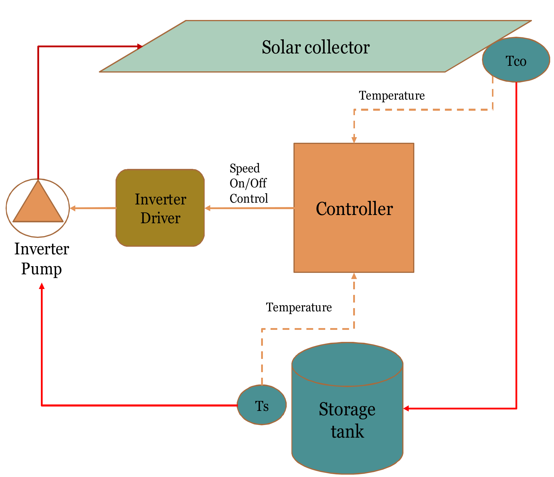
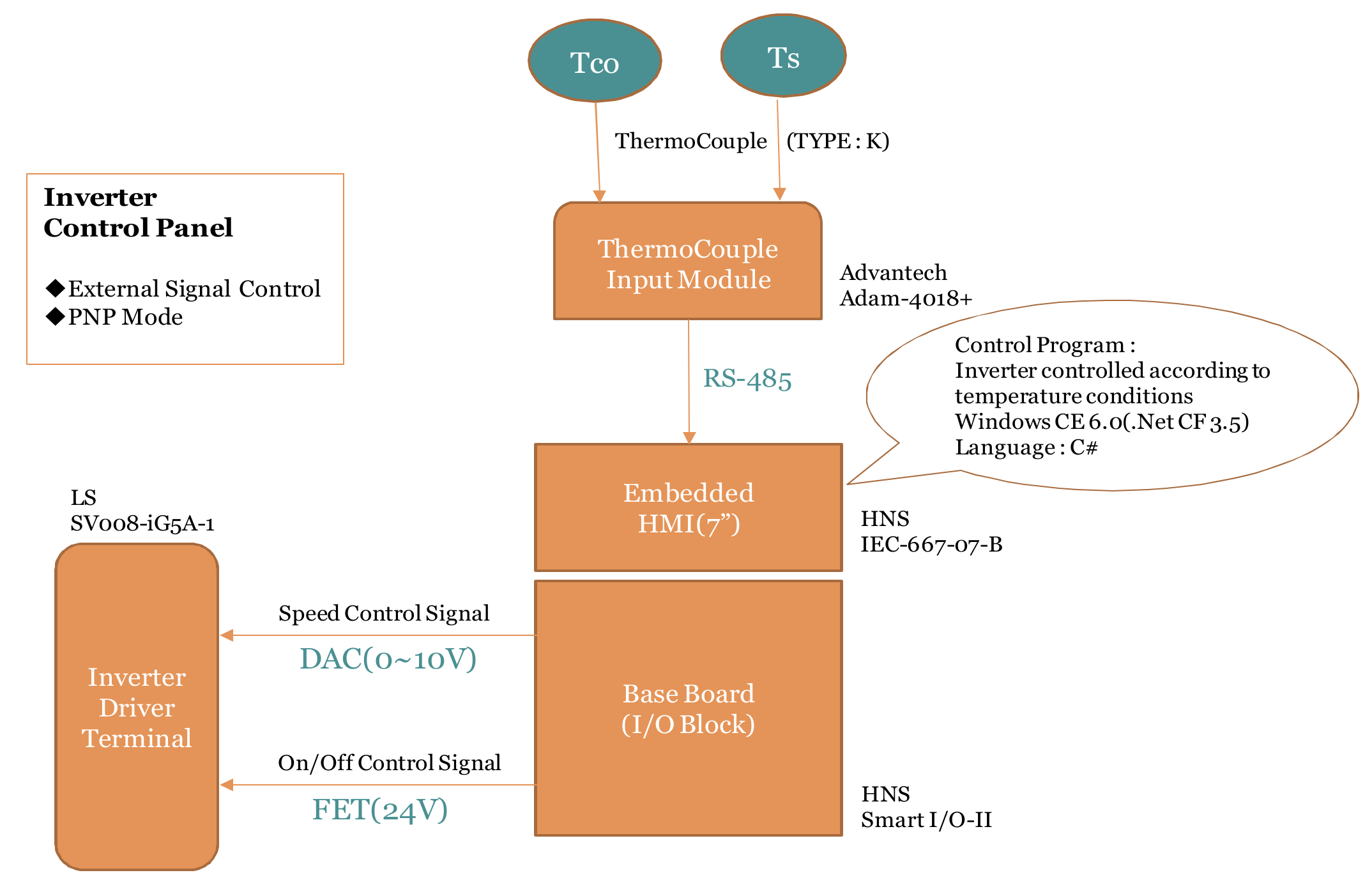
where Us and As are the heat loss coefficient and the total surface area of the thermal storage tank, respectively. In this study, the pump for the collector loop is an inverter pump, and its change in speed depends on the variation of the mass flow rate through the collector loop. The automatic controller will monitor the temperature differences between the evacuated tube collectors and the thermal storage tank, as seen in Figure 2. When the difference between the value of the outlet water temperature Tco of the evacuated tube collectors and the hot water temperature in the thermal storage tank Ts is higher than the set value of Δ T o n ( T c o T s Δ T o n ), the inverter collector pump works and then stops if T c o T s Δ T o f f . The values of Δ T o n and Δ T o f f were chosen as 10 °C and 1.5 °C, respectively [18,19,20,21]. This automatic controller has the module as shown in Figure 3, and this module consists of many small modules such as thermocouples, baseboard (I/O Block), embedded HMI and inverter driver terminal. The inverter collector pump is controlled by an embedded controller with Windows based on C# language. The input of the automatic controller is given by a thermocouple input module that is connected to the embedded controller with RS-485 communication protocol.
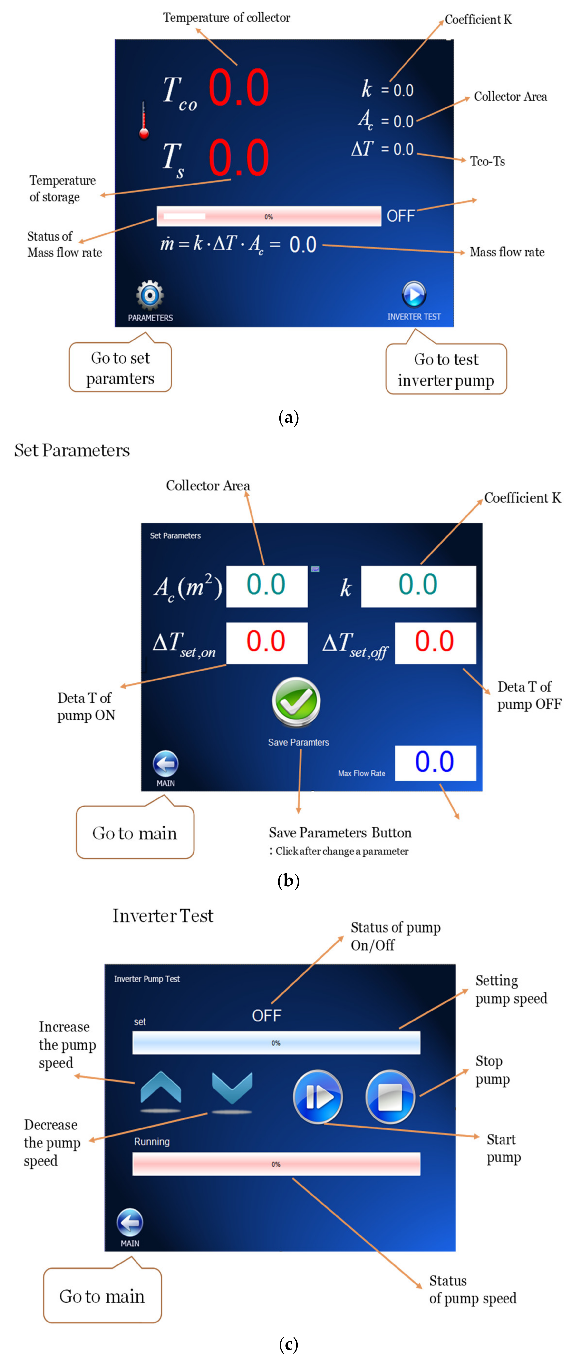
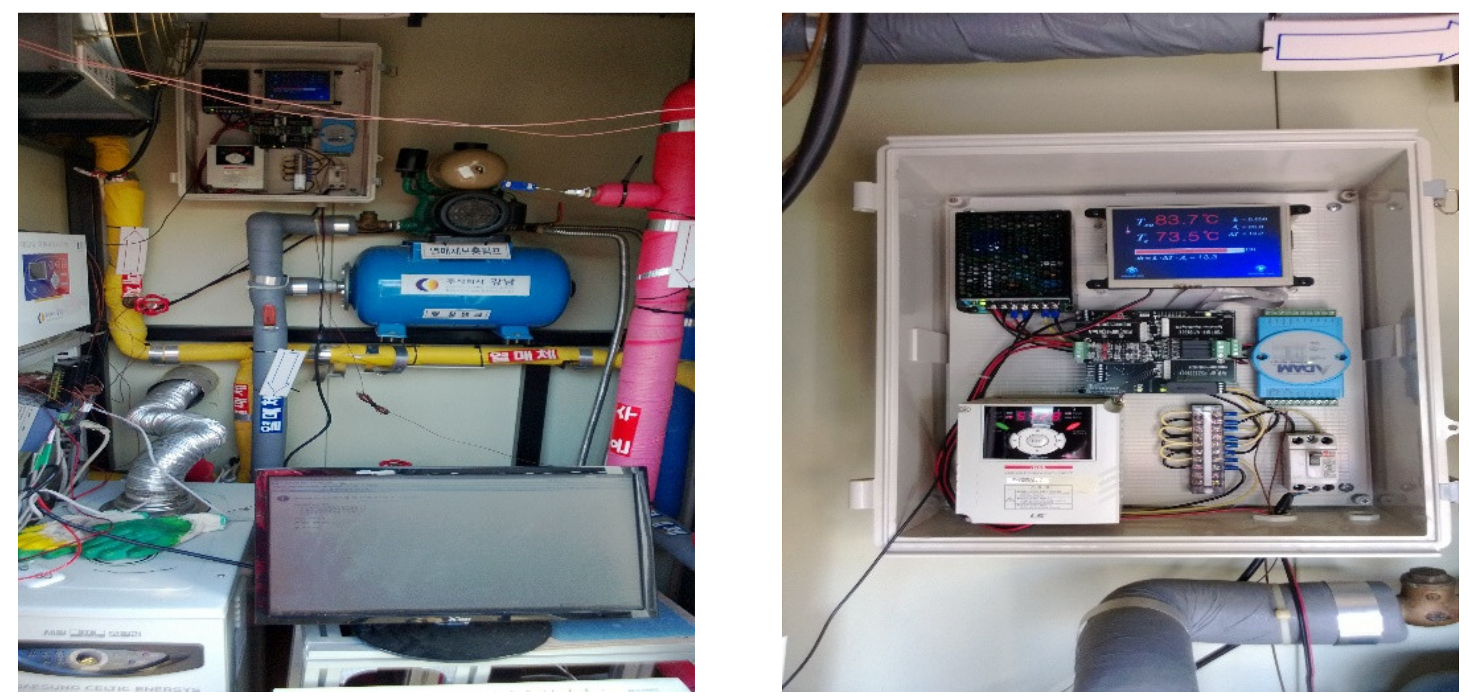
Figure 4 shows the main monitor of the automatic controller. This monitor shows the parameters, such as the flow coefficient Kv (Kv = 0.05, as proposed by [18]) and the collector aperture area Ac (both of which can be changed for the experiment), the hot water temperature Ts in the thermal storage tank, the outlet water temperature Tco of the evacuated tube collectors, the difference in the two temperatures Δ T = T c o T s , and the value of the variation flow rate (determined based on Equation (1)). The whole automatic controller and its operation are shown in Figure 5. The steps for use of the controller are as follows: Firstly, press the parameter button on the main monitor of the automatic controller and the main monitor will appear as in Figure 4a. A series of input parameters of the automatic controller, such as flow rate coefficient k , collector area A c and the temperature set values for switching the inverter collector pump on and off, must be set before pressing the save parameters button (see Figure 4b). Then, press the main button to come back the main monitor. Secondly, to test the operation of the inverter collector pump, press the inverter test button; the main monitor is shown as in Figure 4c. The speed of the inverter collector pump can be changed according to the requirements of the experiment system.

3. Experimental Setup

The experiments were conducted on the rooftop of a residential house on Jeju Island. The latitude, longitude and altitude of Jeju Island are 33°31’N, 126°32’E and 8 m elevation above sea level, respectively. The experiments were carried out from 7:00 a.m. to 5:00 p.m., and values were recorded every 10 s. The ambient temperature was measured using the type K thermocouple (uncertainty of 0.5%), whereas the solar radiation and the variation mass flow rates in the collector loop were measured using a pyranometer (uncertainty of 1.5%) and a magneto-hydrodynamic flow meter (uncertainty of 1%). During the experiments, the system was operated throughout the day without domestic hot water and space heating load. On each day, the hot water in the storage tank was completely drained in the morning and refilled with cold water, so that the initial water temperature of the thermal storage tank at the beginning of each of the experiment days was similar. In this work, to evaluate the stability and the precision of the automatic controller with an inverter collector pump for the solar-assisted heating system, the experiments were conducted on three different days: a clear day, an intermittently cloudy day, and an overcast day. The amplitude of the flow rate through the collector loop was determined according to Equation (1). This work focuses on the stability and the precision of an automatic controller with an inverter collector pump for the variable mass flow rate in the collector loop, as well as the contribution of the useful heat gain of the collector for the solar-assisted heating system. Therefore, the boiler performance, the load of the hot water for space heating and users are not mentioned in this paper.

4. Results and Discussion

The operation of evacuated tube collectors in the case of a fair day is shown in Figure 6. The inverter collector pump operated continuously from 9:02 a.m. until 4:19 p.m., so the collection of solar energy took place during that time frame. When the inverter collector pump operated, the outlet water temperature of the evacuated tube collectors gradually increased in the morning and then gradually decreased in the afternoon, while the inlet water temperature of the evacuated tube collectors continually increased and decreased when the inverter collector pump was turned off. In this case, the increase in the hot water temperature in the thermal storage tank led to an increase in the inlet water temperature of the evacuated tube collectors. The other reason is that the ambient temperature and the solar radiation also increased in the morning and then gradually decreased in the afternoon. The outlet water temperature of the evacuated tube collectors reached its highest value of 64.8 °C at 1:25 p.m. The temperature difference between the inlet and outlet of the collector was approximately in the range of 2 to 13.3 °C. The hot water temperature in the thermal storage tank gradually increased between 9:02 a.m. and 4:19 p.m. The range of variable mass flow rate was from 2.35 to 22.4 L/min. In the first 90 s when the inverter collector pump was started, the variable mass flow rate in the collector loop strongly increased and then gradually decreased. This is because of the heat stored in the material of the collector leading to sudden temperature increase in the outlet collector and then a rapid decrease. The contribution amount of the useful heat gain Qu during the day was 35.1 kWh.
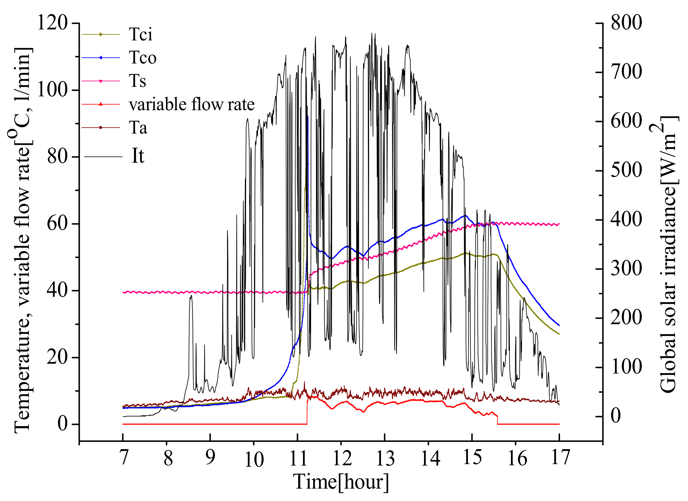
We have seen that the increase in the hot water temperature in the thermal storage tank depends on many factors, such as heat loss of the thermal storage tank, ambient temperature and the amount of transferred energy from the evacuated tube collectors to the thermal storage tank. Figure 7 shows the operation of the evacuated tube collectors on an intermittently cloudy day. The inverter collector pump operated continuously from 11:12 a.m. to 3:38 p.m., and the collection of solar energy also took place between those times. When the inverter collector pump operated, the outlet water temperature and inlet water temperature of the evacuated tube collectors gradually increased until 2:45 p.m. and then gradually decreased. The range of difference between the inlet water temperature and outlet water temperature of the evacuated tube collectors was approximately 2 to 15.3 °C. The hot water temperature in the thermal storage tank gradually increased between 11:22 a.m. and 4:00 p.m. The variable mass flow rates ranged from 2.42 to 8.74 L/min. As seen in Figure 7, the magnitude of the variable flow rate strongly fluctuated between 11:22 a.m. and 3:58 p.m. This is due to the fluctuation of the solar radiation leading to a variation in the outlet water temperature of the evacuated tube collectors. The contribution amount of the useful heat gain Qu during the day was 22.06 kWh.
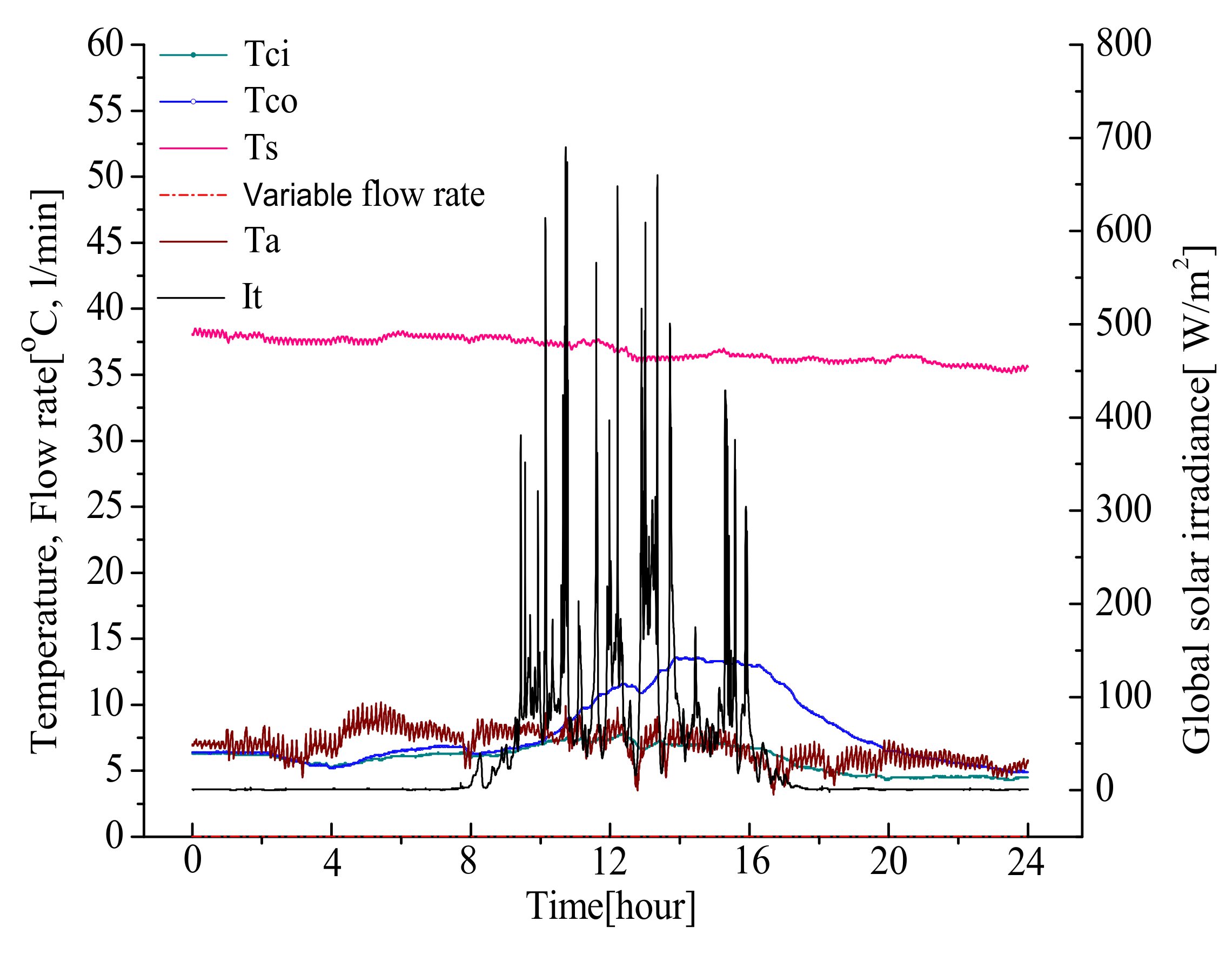
The operation of the evacuated tube collectors on an overcast day is shown in Figure 8. The collector pump was not operated. This is because the amount of solar radiation received on the collector surface was too low during the day. The inlet water temperature and outlet water temperature of the evacuated tube collectors were almost the same as the ambient temperature during the day. The hot water temperature in the thermal storage tank did not oscillate. The amount of useful contribution heat gain Qu during the day was zero.
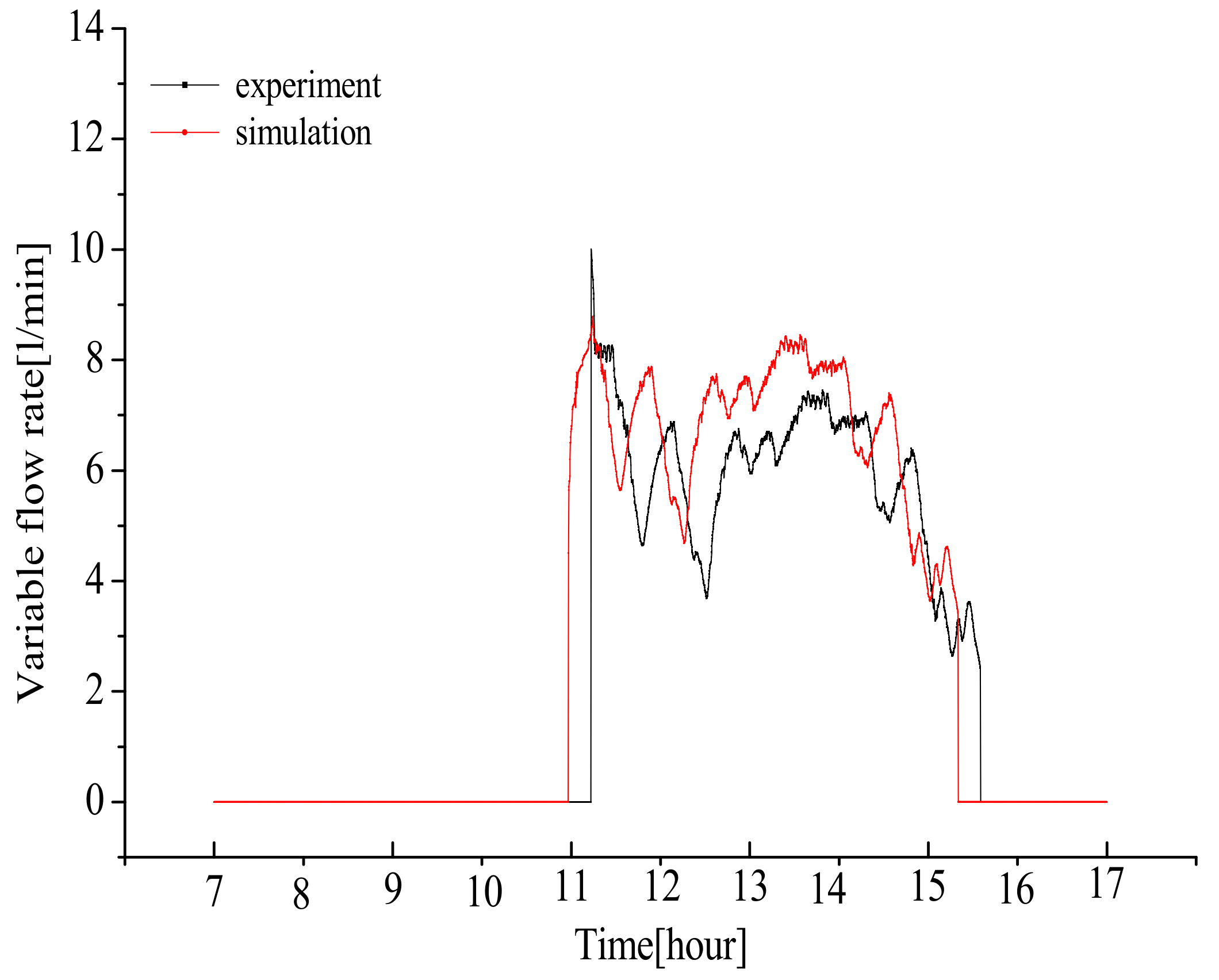
The validation of simulation and experimental results of the variable mass flow rate in the collector loop is shown in Figure 9. The simulation and experiment were both carried out between 7:00 a.m. and 5:00 p.m. on an intermittently cloudy day, and the variable mass flow rate through the collector loop is calculated according to Equation (1) and MATLAB program given in [18]. As seen in Figure 9, the operation of the inverter collector pump of the numerical simulation began at 10:57 a.m. and terminated at 3:24 p.m., while the experiment began at 11:12 a.m. and terminated at 3:38 p.m. When the inverter collector pump was started, in the short time of 90 s of experiment, the amplitude of the variable mass flow rate through in the collector loop rapidly increased and then suddenly decreased; this was higher than the variable flow rate of the numerical simulation. The variable mass flow rate difference between the numerical simulation and the experiment was within 3.85%. This is due to the thermal lag time of the material of the collector. As seen in Figure 9, during the time of operation with the inverter collector pump, the variable mass flow rate in the collector loop strongly fluctuated, which is due to the oscillation in solar radiation.
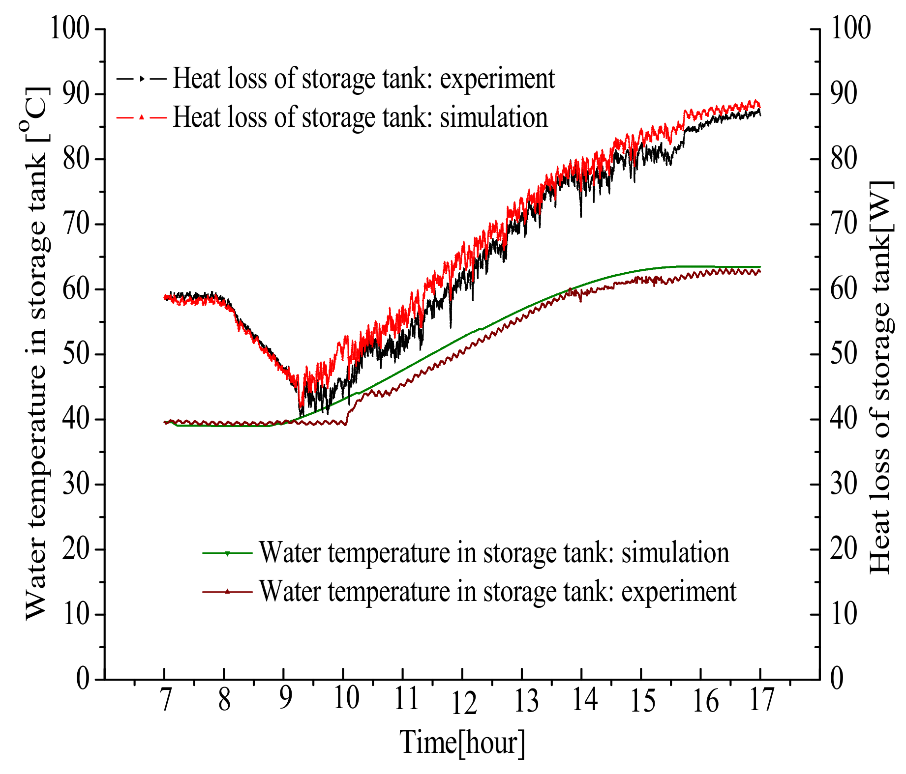
Figure 10 shows the variation in heat loss and the hot water temperature in the thermal storage tank against time on an intermittently cloudy day. The heat loss through the walls of the thermal storage tank gradually decreased between 7:00 a.m. and 9:20 a.m. and then gradually increased, due to the increase in the hot water temperature in the thermal storage tank, the change in solar radiation and the ambient temperature. The difference in the hot water temperature in the thermal storage tank from the numerical simulation and experiment at 5:00 p.m. was 0.75 °C. The comparisons of the simulated and measured total heat loss through the walls of the thermal storage tank and total useful heat gain of the evacuated tube collectors during daytime are summarized in Table 1. Agreement between simulated and measured data is good, with the comparative total heat loss of the thermal storage tank being within 2.34% and total useful heat gain of the evacuated tube collectors being within 3.46%. This lends confidence to the validity of the simulated results. It also shows that the operation of a new automatic controller with an inverter collector pump for solar-assisted heating system is reliable in the poor conditions of an intermittently cloudy day. Therefore, this automatic controller can be applied to industry.

5. Conclusions

The principal objective of this paper was to develop an automatic controller with an inverter collector pump for the collector loop of solar-assisted heating system for experiments and industrial application based on the optimal equation m = 0.05 Δ T A c (kg/min) of the variable mass flow rate through the collector loop given by [18].
The experimental results from three different days, namely a clear day, an intermittently cloudy day and an overcast day, indicated that the contributions of the useful heat gain during the day of these cases were 35.1, 22.06 and 0 kWh, respectively. While the variation of the mass flow rate ranges from 2.35 to 22.4 L/min, the magnitude of the mass flow rate depends on the direct and indirect parameters, such as the outlet water temperature of evacuated tube collectors, the hot water temperature in the thermal storage tank, the collector aperture area, the solar radiation and the load of hot water for users.
The validation of numerical analysis and experimental results of the variable flow rate in the collector loop, with the total heat loss of the storage tank and total useful heat gain of the evacuated tube collectors on the intermittently cloudy day being within 2.34% and 3.46%, respectively, demonstrates that the operation of the automatic controller with an inverter collector pump for the collector loop of the solar-assisted heating system is reliable and precise, even in the poor weather conditions of an intermittently cloudy day. It is expected that this model can be applied to industry soon to improve the performance of solar-assisted heating systems.

Author Contributions

Conceptualization, Y.C.P.; methodology, L.M.N.; software, L.M.N.; validation, L.M.N. and Y.C.P; formal analysis, L.M.N. and Y.C.P.; investigation, L.M.N. and Y.C.P.; data curation, L.M.N.; writing—original draft preparation, L.M.N.; writing—review and editing, Y.C.P.; supervision, Y.C.P.; project administration, Y.C.P.; funding acquisition, Y.C.P. All authors have read and agreed to the published version of the manuscript.

Funding

This research was supported by research grant of Ho Chi Minh City University of Technology and Education, Vietnam, and by the National Research Foundation of Korea (NRF) grant funded by the Korea Government (MSIP) (No. 2020R1A2C1011871).

Conflicts of Interest

The authors declare no conflict of interest.

References

  1. Leonard, M.D.; Michaelides, E.E.; Michaelides, D.N. Substitution of coal power plants with renewable energy sources—Shift of the power demand and energy storage. Energy Conversat. Manag. 2018, 164, 27–35. [Google Scholar] [CrossRef]
  2. Maji, I.K.; Sulaiman, C. Renewable energy consumption and economic growth nexus: A fresh evidence from West Africa. Energy Rep. 2019, 5, 384–392. [Google Scholar] [CrossRef]
  3. Hosseinirad, S.; Nagamune, R.; Grebenyuk, V. An optimal control strategy for a heat pump in an integrated solar thermal system. J. Process. Control. 2019, 84, 35–45. [Google Scholar] [CrossRef]
  4. Badescu, V. Optimal control of flow in solar collector systems with fully mixed water storage tanks. Energy Convers. Manag. 2008, 49, 169–184. [Google Scholar] [CrossRef]
  5. Winn, C.B.; Hull, D.E. Optimal controllers of the second kind. Sol. Energy 1979, 23, 529–534. [Google Scholar] [CrossRef]
  6. Kvarrik, M.; Lesse, P.F. Optimal control of flow in low temperature solar heat collector. Sol. Energy 1976, 18, 431–435. [Google Scholar] [CrossRef]
  7. Orbach, A.; Rorres, C.; Fishchl, R. Optimal control of a solar collector loop using a distributed-lumpedmodel. Automatica 1981, 17, 535–539. [Google Scholar] [CrossRef]
  8. Saltiel, C.; Sokolov, M. Optimal control of a multicomponent solar collector system. Sol. Energy 1985, 34, 463–473. [Google Scholar] [CrossRef]
  9. Beckman, W.A.; Thornton, J.; Long, S.; Wood, B.D. Control problems in solar domestic hot water systems. Sol. Energy 1994, 53, 233–236. [Google Scholar] [CrossRef]
  10. Furbo, S.; Shah, L.J. Optimum solar collector fluid flow rates. In Proceedings of the Eurosunʹ96, Freiburg, Germany, 16–19 September 1996. [Google Scholar]
  11. Ardehali, M.M.; Yae, K.H.; Smith, T.F. Development of proportional-sum-derivative control methodology. Sol. Energy 1996, 57, 251–260. [Google Scholar] [CrossRef]
  12. Pichler, M.F.; Lerch, W.; Heinz, A.; Goertler, G.; Schranzhofer, H.; Rieberer, R. A novel linear predictive control approach for auxiliary energysupply to a solar thermal combistorage. Sol. Energy 2014, 101, 203–219. [Google Scholar] [CrossRef]
  13. Bujedo, L.A.; Rodríguez, J.; Martínez, P.J. Experimental results of different control strategies in a solarair-conditioning system at part load. Sol. Energy 2011, 85, 1302–1315. [Google Scholar] [CrossRef]
  14. Ntsaluba, S.; Zhu, B.; Xia, X. Optimal flow control of a forced circulation solar water heating system with energy storage units and connecting pipes. Renew. Energy 2016, 89, 108–124. [Google Scholar] [CrossRef] [Green Version]
  15. Facao, J. Optimization of flow distribution in flat plate solar thermal collectors with riser and header arrangements. Sol. Energy 2016, 120, 104–112. [Google Scholar] [CrossRef] [Green Version]
  16. Abdellah, S.; Junaid, J.O.; Mehdi, K.; Ataollah, N. Enhancing heat pipe solar water heating systems performance using a novel variable mass flow rate technique and different solar working fluids. Sol. Energy 2019, 186, 191–203. [Google Scholar]
  17. Nhut, L.M.; Park, Y.C. A study on automatic optimal operation of a pump for solar domestic hot water system. Sol. Energy 2013, 98, 448–457. [Google Scholar] [CrossRef]
  18. Duffie, J.A.; Beckman, W.A. Solar Engineering of Thermal Processes, 3rd ed.; Wiley: Hoboken, NJ, USA, 2006. [Google Scholar]
  19. Knudsen, S. Consumers’ influence on the thermal performance of small SDHW systems. Sol. Energy 2002, 73, 33–42. [Google Scholar] [CrossRef]
  20. Csordas, G.F.; Brunger, A.P.; Hollands, K.G.T.; Lightstone, M.F. Plume entrainment effects in solar domestic hot water systems employing variable-flow-rate control strategies. Sol. Energy 1992, 49, 497–505. [Google Scholar] [CrossRef]
  21. Reindl, D.; Kim, S.K.; Kang, Y.T.; Hong, H. Experimental verification of a solar hot water heating system with a spiral-jacketed storage tank. J. Mech. Sci. Technol. 2008, 22, 2228–2235. [Google Scholar] [CrossRef]
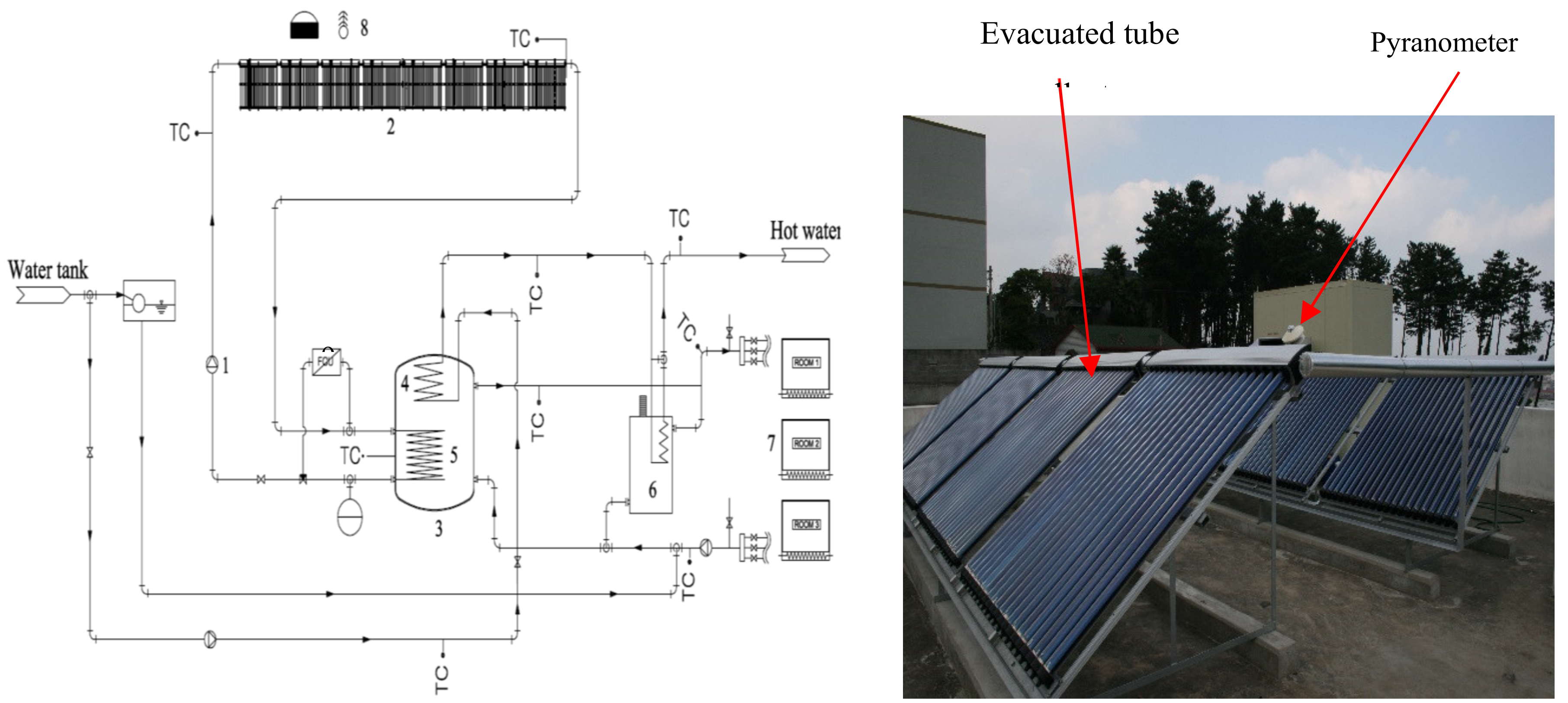
Figure 1. Schematic diagram of the solar-assisted heating system. (1) Inverter collector pump, (2) evacuated tube collector, (3) thermal storage tank, (4) heat exchanger of domestic hot water, (5) heat exchanger of collector loop, (6) oil boiler, (7) panel heating, (8) ambient temperature sensor and pyranometer and (9) fan coil unit (FCU). This figure is reprinted from Journal of Solar Energy, Vol. 98, Le Minh Nhut and Youn Cheol Park, A Study on automatic optimal operation of a pump for solar domestic hot water system, Pages No. 448-457, Copyright (2020) with the permission of Elsevier.
Energies 13 02128 g001
Figure 2. Schematic diagram of the solar-assisted heating system with an inverter collector pump in the collector loop. This figure is reprinted from Journal of Solar Energy, Vol. 98, Le Minh Nhut and Youn Cheol Park, A Study on automatic optimal operation of a pump for solar domestic hot water system, Pages No. 448-457, Copyright (2020) with the permission of Elsevier.
Energies 13 02128 g002
Figure 3. Module of the automatic controller with an inverter collector pump in the collector loop.
Energies 13 02128 g003
Figure 4. The main monitor of the automatic controller: (a) main monitor, (b) input parameters, (c) status test of the inverter collector pump
Energies 13 02128 g004
Figure 5. View of the front of the automatic controller.
Energies 13 02128 g005
Figure 6. Operation of evacuated tube collectors on a clear day.
Energies 13 02128 g006
Figure 7. Operation of evacuated tube collectors on an intermittently cloudy day.
Energies 13 02128 g007
Figure 8. Operation of evacuated tube collectors on an overcast day.
Energies 13 02128 g008
Figure 9. Profile of variable mass flow rate of simulation and experiment on an intermittently cloudy day.
Energies 13 02128 g009
Figure 10. Variation of heat loss and water temperature of thermal storage tank on an intermittently cloudy day.
Energies 13 02128 g010
Table 1. Comparison of total heat loss of the thermal storage tank and total useful heat gain of the evacuated tube collectors by simulation and experiment on an intermittently cloudy day.
Useful   Heat   Gain   of   the   Evacuated   Tube   Collector   Q u Heat   Loss   of   the   Thermal   Storage   Tan k   Q st
ExperimentSimulationExperimentSimulation
22.3 (kWh)23.1 (kWh)67.95 (Wh)69.58 (Wh)