Article

Impact of Core Sheet Cutting Method on Parameters of Induction Motors

Institute of Mechatronics and Information Systems, Lodz University of Technology, 90-924 Lodz, Poland
*
Author to whom correspondence should be addressed.
Energies 2020, 13(8), 1960; https://doi.org/10.3390/en13081960
Submission received: 12 March 2020 / Revised: 5 April 2020 / Accepted: 9 April 2020 / Published: 16 April 2020
(This article belongs to the Section C: Energy Economics and Policy)

Abstract

:
The method of cutting motor core sheets causes a change in their magnetic properties and core losses, especially additional losses. Reducing motor losses is very important because of the fulfillment of increasingly stringent requirements set by international regulations for reducing electricity consumption. Due to fact that more and more often induction motors are supplied with high-frequency voltage, core losses are beginning to play a dominant role in the motor’s loss balance. That is why accurate determination of these losses is very important and cutting has a significant impact on them. This report shows how the method of cutting sheet metal affects losses in the finished induction motor working in a wide frequency range. The paper presents the impact of various motor core fabrication technologies on its operational parameters and an approximate way of including this impact in analytical calculations at the design stage of new machine designs, as it is necessary to use sheet metal cutting technologies such as laser or electrical discharge machining (EDM) at the prototype stage. The proposed method is based on measurements of sheet parameters made on toroidal samples with appropriately selected dimensions, so that the width of the sample corresponds to the average width of the motor core elements.

1. Introduction

The increasing use of induction motors powered by voltage from pulse width modulation inverters (PWM) inverters with increased frequency (300–400 Hz) causes a greater impact of core loss on the final efficiency of the motor. It is well known that the processes associated with obtaining the appropriate shape of the sheets of an induction motor are associated with a change in the structure of the sheet metal, which results in a deterioration of magnetic properties and an increase in losses. For cutting, punching is generally used as the most effective method, however, associated with the need to make expensive tools often with punches and dies made of a tungsten carbide or ceramic. The mechanical cutting is connected with material plastic deformation and strain hardening phenomena appear at the cut edge. Less commonly used methods, usually for small-scale series of products or prototypes are: laser cutting, wire-cut electrical discharge machining (spark erosion, EDM), or abrasive water jet cutting [1,2,3,4]. From those methods, the last two are known to have the lowest impact on the magnetic quality of the material, and their use is only suitable for small quantities due to their slow cutting speed and oxidation or corrosion phenomena. The laser cutting induces thermal stresses, due to small heat affected zone apparitions. In abrasive water jet cutting, a high pressure pump with abrasive particles is used. In spark erosion usually a tensioned travelling wire electrode is involved. The area of the core material subjected to degradation depends on the cutting method and can be up to several millimeters. The samples cut by shearing have the cut-edge residual stress affected zones of 200–300 μm [5]. Therefore, especially for small machines for which the stator and rotor tooth widths do not exceed 10 millimeters and the yoke height is small, the impact of the cutting method can be very significant. Depending on the manufacturing technique the penetration depth of the degradation zone can be up to several millimeters [4]. This process increases the losses especially for smaller machines, where the stator teeth might be completely affected by degradation [6]. This effect is further enhanced by not using the core annealing process after cutting for these machines due to the desire to minimize manufacturing costs. Paper [7] for example analyzed the positive impact of annealing on the magnetic properties and on the efficiency of 4 kW induction machines. Usually the effect of processing was investigate using one of standardized characterization methods like Epstein, single sheet, or toroidal ring tests [8,9].
The effect of punching parameter variations on the magnetic properties of eight different nongrain-oriented electrical steels was investigated by using a single-sheet tester in [10] showing the influence of the state of the punching device on losses. In that paper, the simulation of losses in PMSM due to punching effect was also investigated. According to [11], the length of the affected area did not exceed 1 mm. In [12], a particular structure made of a stack of skeleton stators, in which only slots were punched using an industrial process, were used for the punching effect investigation. The authors state that in electric machines the teeth are usually very saturated and then the punching effect is negligible. As mentioned in paper [13], measurements made for a similar sheet M330-35A shows an increase in specific core losses between 15 and 3 mm samples, for a frequency of 500 Hz, and about 30% near flux density 1 T and only 6% at 1.7 T. Therefore, more attention must be paid to motors operating in a wide frequency range, which for higher frequencies operate in the field weakening range, and therefore, unlike machines built only for 50 Hz, the saturation of the magnetic circuit is definitely lower. Article [14] shows that for different frequencies the effect of cutting can be different, especially when using a laser. At low frequencies power loss is lower for fiber laser cut samples, like shown in [14]. Machines designed to operate in a wide frequency range require a different approach than machines operating only at 50 Hz. For machines operating only at 50 Hz as the article indicates, the share of core losses in total losses decreases as the efficiency increases [15,16].
In paper [17], degradation profile reaching a depth of 2 mm was used and the specific hysteresis loss increased inversely with the degradation profile. However, in paper [18], authors suggested that with increasing frequency, the influence of magnetic deterioration by cutting is reduced explaining this by the increasing eddy currents which, unlike the cutting effect, increase the flux at the edge of the sheet.
The cutting process mainly affects the hysteresis component of the iron losses [19,20,21]. However, the plastic deformation after cutting also affects the eddy current losses. The possible reason for this is the degradation of the insulation which leads to lower apparent resistivity and change of electric conductivity of the core material.
Usually experiments are conducted on specimens composed of strips of variable width [22]. Not much work is done to study the impact of punching on the basis of loss tests on the machine. Such studies were presented in the article [23], but for a reluctance motor with a slightly different geometry (synchronous, a similar stator but a completely different rotor) than induction motors.
This paper deals with the impact of core sheet cutting method on the parameters of made induction motors. The object of the study were two low-voltage induction motors used in drives operating in a wide frequency range of the supply voltage (from 10 to 350 Hz). We research and compare punching, laser cutting and spark erosion (EDM) to cover the established series production and prototyping techniques. The sheets of tested machines were not annealed after cutting, because it is not usually used for low and medium power machines. A method of measuring the average electrical steel sheets characteristics on toroidal samples of appropriate width has also been proposed. The possibility of incorporate the characteristics obtained in this way into analytical calculations was presented, thanks to which it is possible to obtain better accuracy of determining motor parameters, especially in the core losses and efficiency.
The operating parameters of induction motors, especially losses and efficiency depend significantly on the magnetic material from which the machine core is made. This applies mainly to high-speed motors powered with a voltage of frequency greater than 100 Hz [24], because as the frequency of the voltage supplying the motor increases, the proportions of losses in this motor change and the core loss begins to play an increasingly important role. Therefore, electrical steel with good magnetic properties should be used for energy-saving motor cores, but at the same time with the lowest possible loss. When choosing the core material, one should also take into account the technological aspects related to the ease of punching the core as well as economic considerations. For this reason, very thin sheets with very low losses are often given up, e.g., from amorphous sheets or electrical sheets less than 0.2 mm thick, while it seems appropriate to use sheets less than 0.5 mm thick, e.g., also used for transformer cores 0.35 mm thick, having lower efficiency than commonly used for cores of electrical machines 0.5 mm thick, but with a similar price.

2. The Cutting Methods of Cores of Induction Motors

Obtaining the right shape of the stator core and rotor is an absolutely necessary element of the induction motor manufacturing process. Despite the emergence of new technologies, such as molding from powders [25], cutting electrical steel laminations remains the most commonly used method. As cutting methods: punching, wire electrical discharge machining (EDM) [26], laser [27] and abrasive water jet (AWJ) methods are used. The best results are obtained when cutting metal sheets for the cores of electric machines using a mechanical punch. However, this is only possible for mass-produced machines due to the high cost of making the tools. In the case of developing new constructions, at the stage of creating their models, the construction of a new punch is very expensive, so other core punching technologies should be sought. The impact of the cutting method on material properties are related to the physics of the cutting process. In the case of a laser, the laser beam is irradiated onto the surface of the material and the energy of light is absorbed and converted into thermal energy. As a result, the temperature at the irradiation site is rapidly increased, which causes the material to melt and evaporate. The metal vapors expand quickly causing a micro explosion and the molten material is ejected at high speed to generate a highly directional anti-shock wave. These phenomena also affect the material adjacent to the emerging hole. The wavelength of the optical fiber laser is 1.06 µm, so is more easily absorbed by the metal material compared with the wavelength of CO2 which is 10.6 µm therefore fiber laser is used most often. According to producers data heat affected zone width is very small 0.04–0.06 mm [28]. Used laser has a maximum power of 2 kW and a cutting speed up to 150 m/min. In EDM, a discharge occurs in the small gap between the workpiece and the electrode, which removes the material by melting or evaporation. In this process, the electrode and workpiece should be immersed in a dielectric fluid. The basis of this process is the ability of controlled electric sparks to erode the material. The amount of material removed using one spark is small, but the discharge occurs several hundred thousand times per second. The discharge causes high heating of the material, melting small amounts of material. This excess material is removed with a constant flow of dielectric fluid. The liquid is also useful for cooling during processing. The advantage of EDM machining is the ability to process the entire stator or rotor package at once. However, the cutting time is much longer than during laser cutting. Affected zone width is almost the same as for laser cutting. In our research, a fiber laser and EDM machine were used.

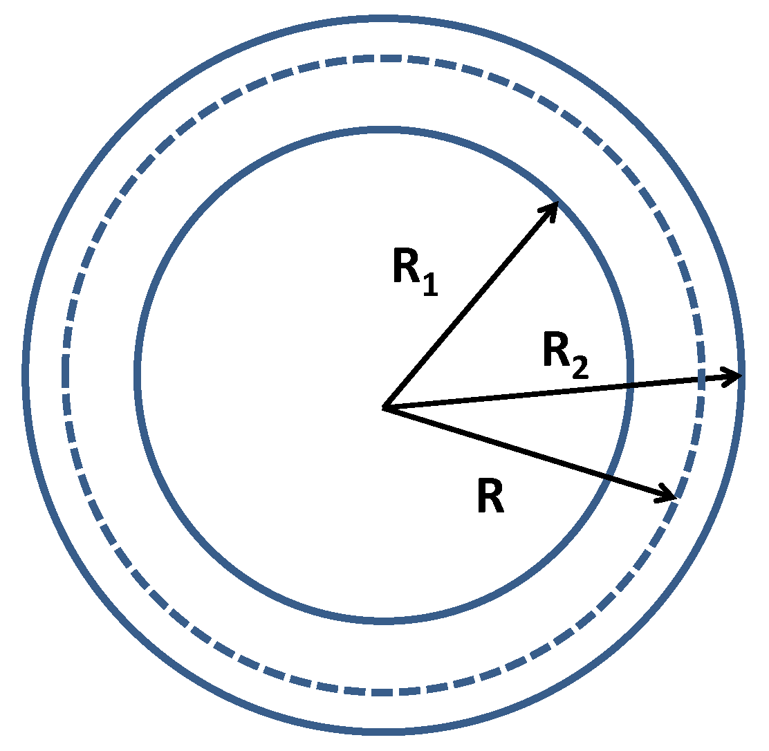
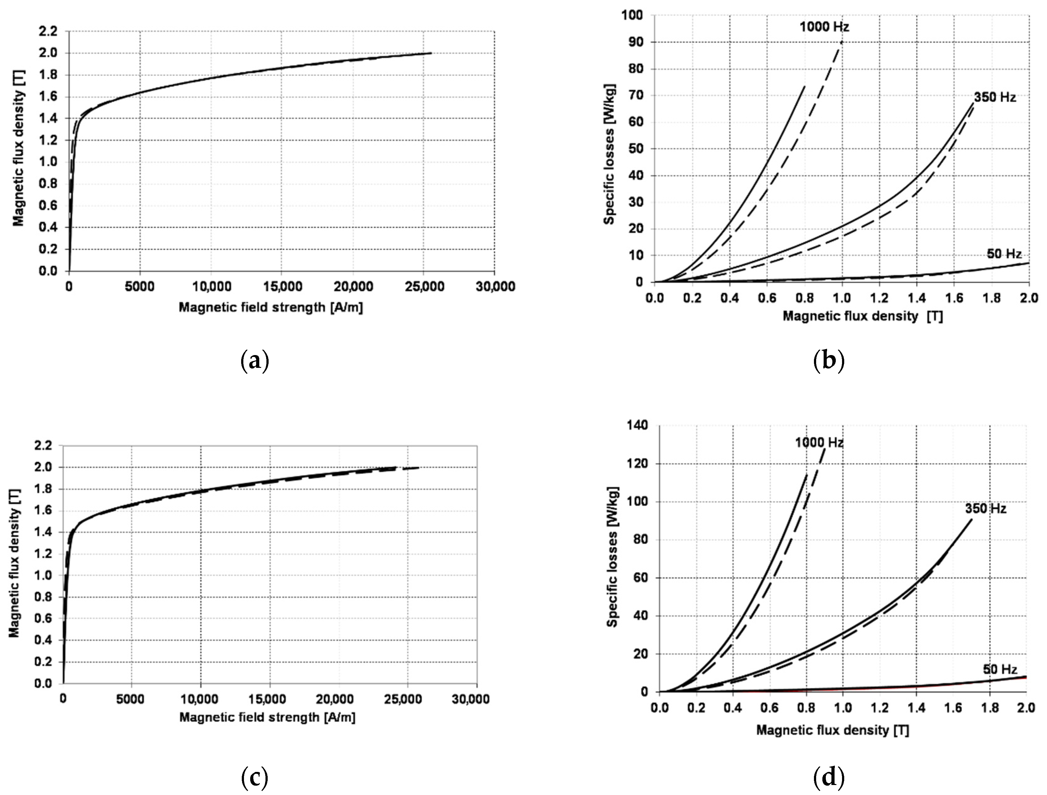
3. Impact of Toroidal Sample Dimensions on the Magnetization Curve and Loss of Electrical Steel

Calculation of losses in the motor core is based on measurements of material specific losses from which the core is made. For this purpose, we use measurements on toroidal samples (Figure 1 and Figure 2), which in our opinion better reflect phenomena occurring in a real machine than measurements using an Epstein apparatus or a single sheet tester, especially for higher frequencies.
The tests were carried out on two types of toroidal samples: wide with diameters D1 and D2 equal to 70 and 120 mm and narrow with accordingly 400 and 420 mm, respectively (radiuses R1 and R2 equal to 35 and 60 mm and narrow with accordingly 200 and 210 mm, respectively). Figure 3 shows comparison of BH curves and specific losses versus magnitude of magnetic flux density measured for both samples in a wide range of frequencies. Samples were cut using a laser.
We can observe that the difference between BH is not significant but specific losses for second sample are much higher. This confirms the statement already known from the literature [1,29,30,31,32,33] that laser cutting increases losses in the core material. A similar phenomenon is observed when cutting EDM or mechanical, but it is not so pronounced. Even if a laser and EDM cutting base on a similar physical phenomena, the cooling process that is very effective for EDM, causes much higher specific loss increases for a laser.
As can be seen from the numerical models of the cutting process, it changes the material properties [26,27]. These properties change with the distance from the cutting edge. For this reason, it is impossible to measure the material properties in the cut impact zone. For this reason, we suggest measuring the property on a sample whose width corresponds to the average width of the core elements (yoke and teeth). It should be noted that to obtain adequate homogeneity of the field inside the sample it should have a sufficiently large diameter. This fact is often disregard in measurements on toroidal samples.
A list of measured values of magnetization and specific losses (at selected supply voltage frequencies) of both grades of sheets obtained for two different samples are given in Table 1—for M270-35A sheets and in Table 2—for M470-50A sheets, respectively.
The purpose of applying two different electric steel sheet grades to the cores of the motors was to see how the parameters of the sheet effect on losses in the motor core and, as a result, its efficiency. The 0.5 mm thickness M470-50A is an electrical steel sheet commonly used in current electrical machines and from this sheet the motor 1 series-produced has been made. Motor 2 is a newly developed energy-efficient design that should replace the currently produced motors, i.e., to reduce core loss in this motor, especially at higher frequencies, it uses the M270-35A sheet with a thickness of 0.35 mm and slightly less specific loss. The use of electric steel sheet with even better parameters, e.g., 0.2 mm thickness of NO20 for economic reasons is unjustified.

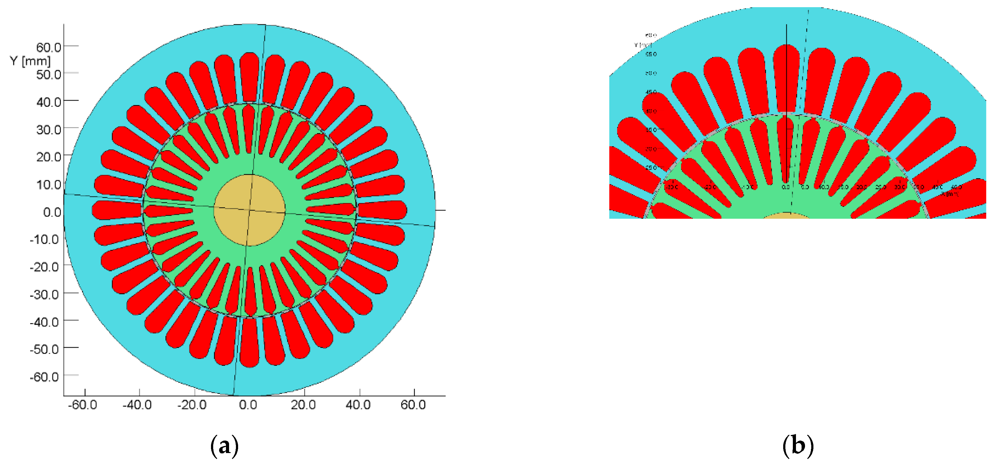
4. Object of Investigation

Until now, testing of the impact of cutting was only carried out on material samples. The purpose of the research was to check the impact of cutting on the parameters of the induction motor made.
As mentioned earlier, the objects of the study were two low-voltage induction motors used in drives operating in a wide frequency range of the supply voltage (from 10 to 350 Hz). The first motor with a shaft height of 71 mm has a core of M470–50A sheet steel 0.5 mm thick (motor 1 shown in Figure 4) made using two technologies: a mechanical punching (1P Motor) and a laser (1L Motor).
As we already mentioned, punching the core with the help of a die is the best technology that causes the least damage to electrical steel sheets, but to make such a core there must be a tool adapted to the designed structure, which is very expensive. Therefore, in the production of model motors, this technology cannot be used. Therefore, other technologies are used to make the cores of model motors, such as laser cutting or EDM. For this reason, the second motor with a shaft height of 90 mm has a core of M270–35A sheet steel 0.35 mm thick (motor 2 shown in Figure 5), and was made using two technologies: electro-erosion (2EDM motor) and laser (2L motor).
The basic design data for both motors are summarized in Table 3. The use of different technologies core punching is often used during the development of new motor designs. During prototyping, machine models with various core shape and sizes and a different number and dimensions of stator and rotor slots are often tested. Making a punch for each designed structure is very expensive, so it is necessary to use a different, less expensive core technology. However, one should be aware to what extent the performance characteristics measured for these models will differ from the results obtained for machines with cores made with the use of a punch.

5. Test Results

Measurements of operational characteristics as well as losses and efficiency were made for all motors constituting the test object, with the motors being supplied with 10, 20, 50, and 350 Hz, both for no-load condition and for rated load.

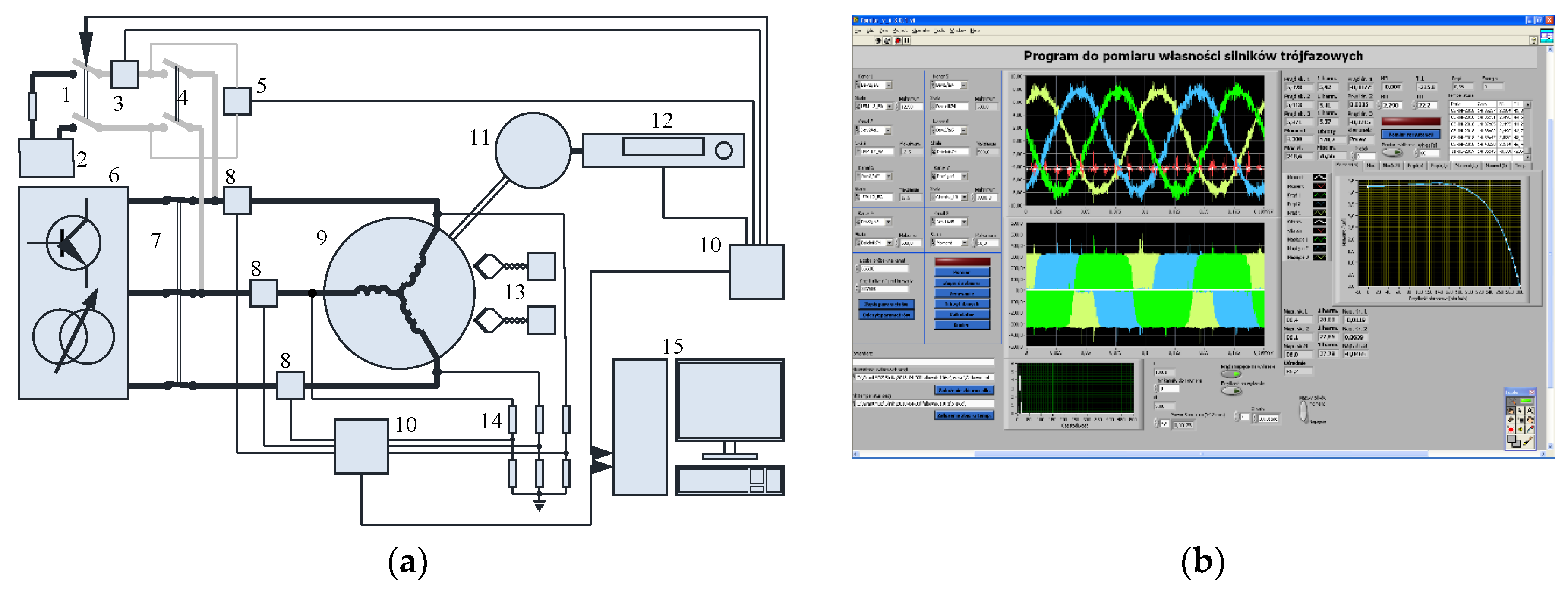
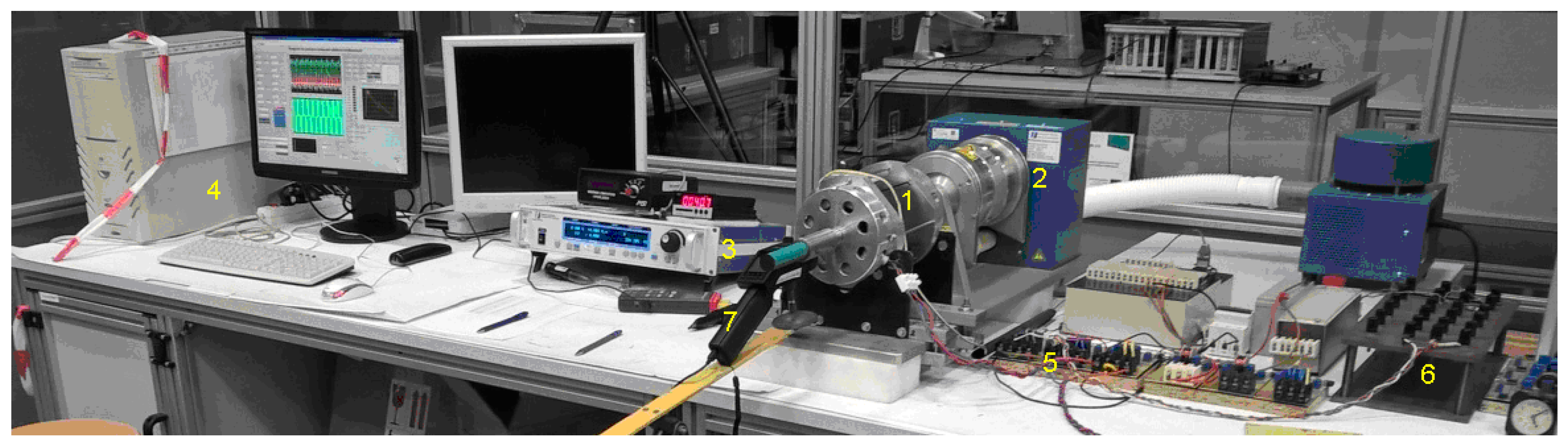
5.1. Measuring System

In order to measure the characteristics of the motors in a broad range of loads and supply parameters, a versatile measurement circuit was built (Figure 6 and Figure 7). The motors were supplied either from a PWM converter or a sinusoidal 50 Hz voltage regulator. The load torque and speed were measured and controlled with a hysteresis dynamometer. All of the measurement data were recorded simultaneously, digitally with the use of a specially created, dedicated software. Because of the distorted voltages and currents the maximal available sampling frequencies and record lengths were used. The resistance and temperature of the windings were measured at standstill, directly before and after other measurements. The temperature of the casing and rotor were measured by independent data loggers in absolute time—to synchronize with other measurements.
The software controlled the sensitivity of the gauges used, recorded and displayed the instantaneous values of the measured quantities, It also calculated and displayed the basic integral values of apparent and active power, RMS, and first harmonics of phase voltages and currents, resistance, and temperature. Chosen characteristics and dependencies, created from subsequent measurements, could also been displayed online. The instrumentation accuracies satisfied the requirements of IEC 60034-2-1 standard (also IEEE 112) [34]. Additionally, the mechanical no-load losses were measured for the entire range of rotor speeds using an accurate torque transducer placed between the tested unsupplied driven motor and an additional driving motor.

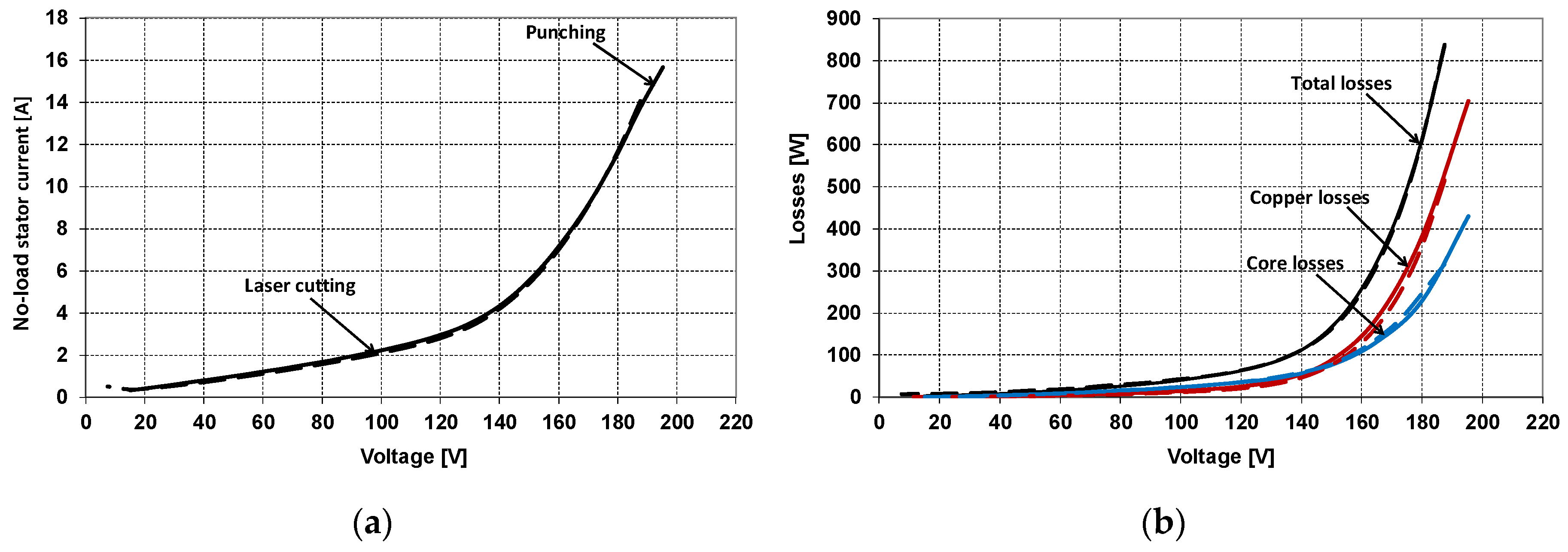
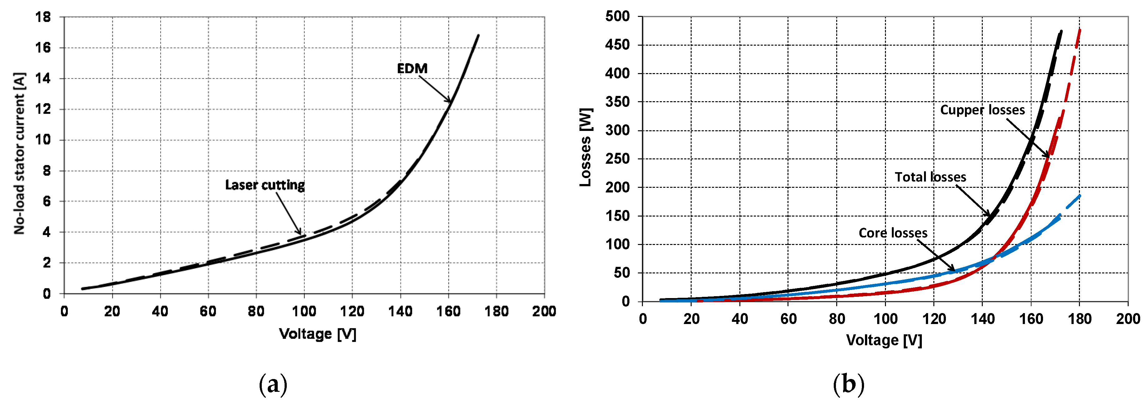
5.2. Measurement Results for No-Load

The no-load characteristics for all motors were determined with mains voltage of 50 Hz. Figure 8 compares the characteristics for currently produced motor 1 with a core, manufactured with mechanical punching with the same motor, but with core sheets cut with a laser.
Such a comparison allows to assess the effect on motor parameters only the change in core technology.
Figure 9 shows similar characteristics for motor 2 with a core made using a laser and an EDM machine. This motor is a proposition of a new construction and has new dimensions of stator and rotor cores and slots, so the punch and die have not yet been made for this motor, however, to verify design calculations, this motor was made using both technologies and subjected to laboratory tests.
As it results from Figure 8 and Figure 9, the technology of making the core sheet has very little effect on the no-load characteristics of the motor operating at mains frequency 50 Hz, because in these conditions basic losses in the core caused by the first harmonic of magnetic induction dominate. The use of a laser for cutting the core gives slightly larger losses in the core than cutting with the help of a punch, and practically the same losses in the core as when using EDM technology.

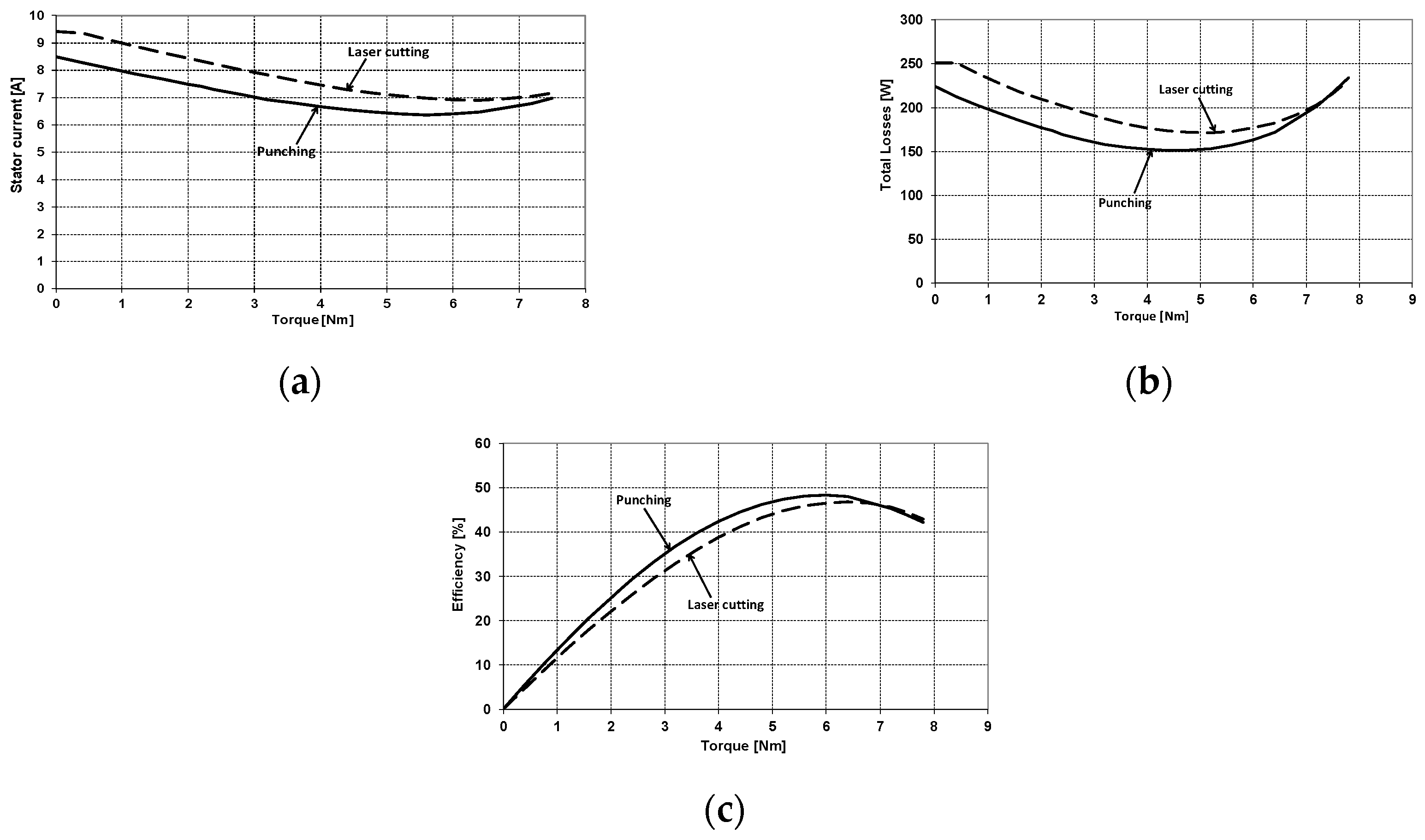
5.3. Measurement Results for Load Condition

The impact of sheet metal cutting technology under motor load conditions was also analyzed. The characteristics of the stator winding current, losses in the motor core, total losses and efficiency of the motor under load conditions variation with torque for all motors, when powered from the inverter, have been determined for different values of the fundamental voltage harmonic frequency (10, 20, and 350 Hz).

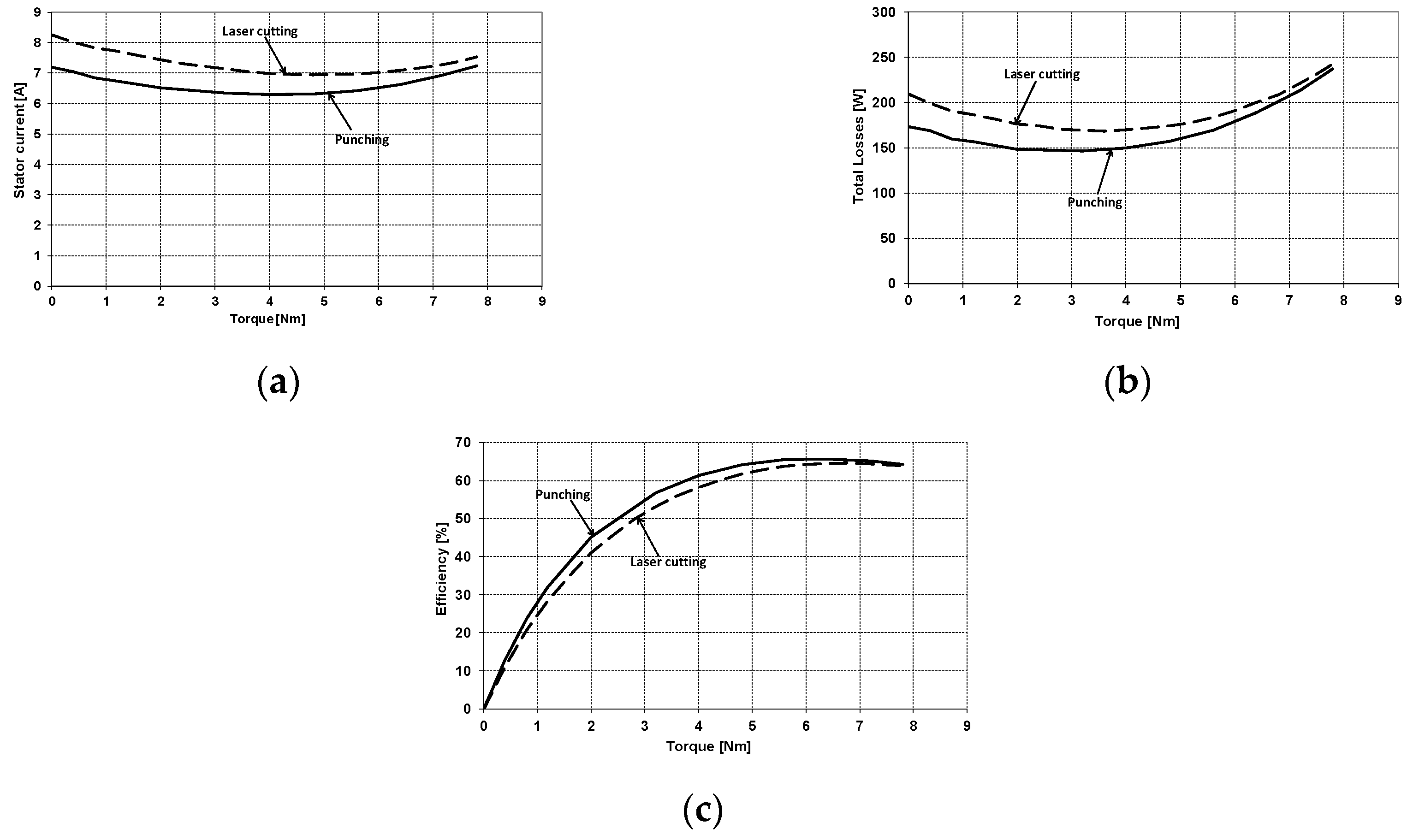
5.3.1. The Load Characteristics of the Investigated Motors for Frequency 10 Hz

Figure 10 shows the load characteristics of motor 1 as a function of torque on the shaft when powered from the inverter with a voltage with a harmonic fundamental frequency of 10 Hz.
As shown in Figure 10 and Table 4, the use of laser technology to make sheets of the motor core made of M470-50A material, at motor on no-load and low loads gives greater current in the stator winding, greater overall losses, and as a result lower motor efficiency than in the same motor with a core made using a punching. The impact of the made core technology while at a frequency of 10 Hz supply voltage decreases as the load of the motor increases, which is associated with a decrease in the value of current in the motor windings.
Figure 11 and Table 5 presents analogous load characteristics of motor 2 as a function of torque on the shaft when supplied from the inverter with a voltage with a fundamental harmonic frequency of 10 Hz.
In motor 2, the impact of the core technology when powered with a frequency of 10 Hz is much smaller, which may indicate that the use of an EDM machine for punching the core gives better results than the use of a laser, but causes more core material degradation than mechanical punching.

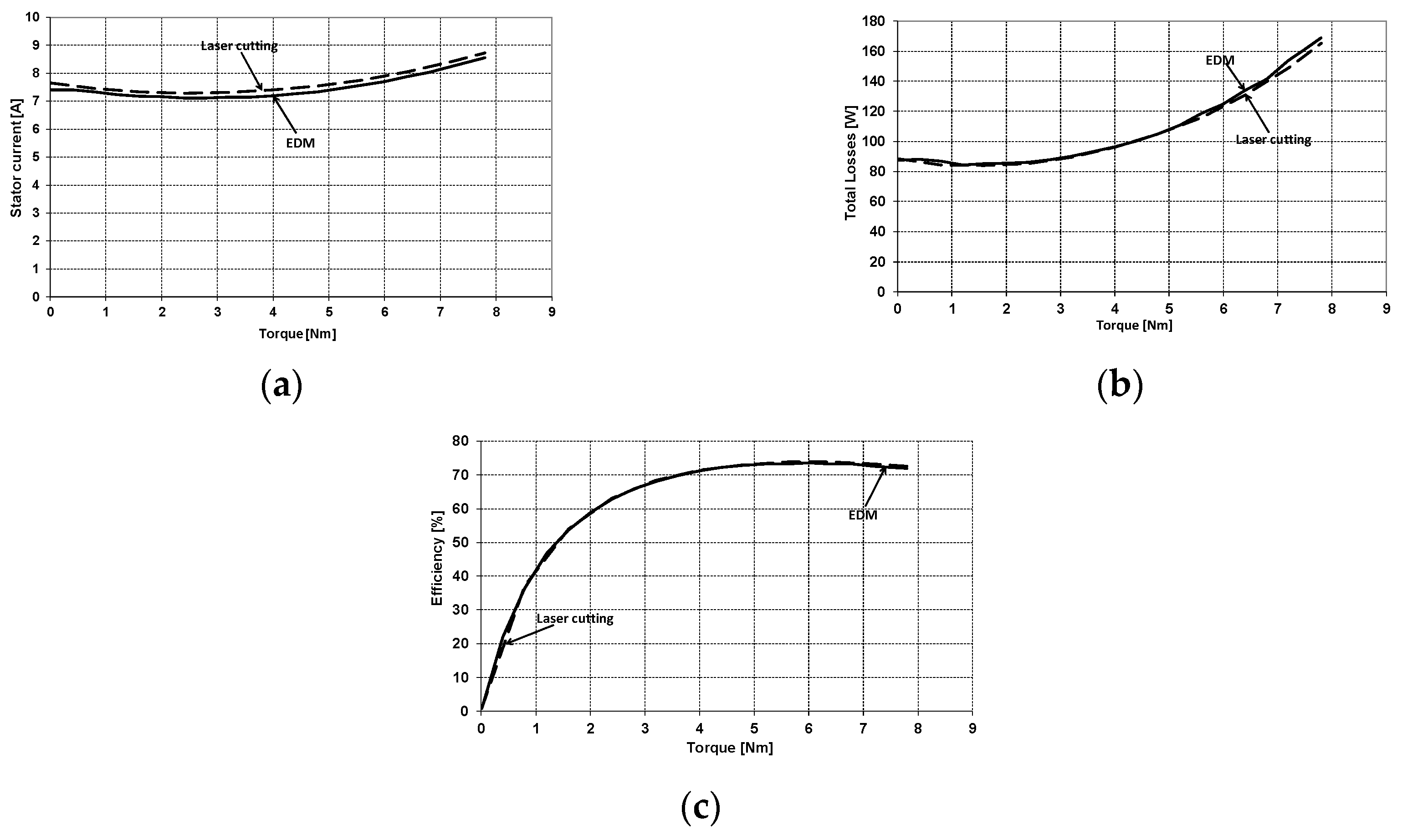
5.3.2. The Load Characteristics of the Investigated Motors for Frequency 20 Hz

Figure 12 and Table 6 shows the load characteristics of motor 1 as a function of torque on the shaft when powered from the inverter with a voltage of 20 Hz fundamental harmonic frequency.
In Figure 13 and Table 7, however, analogous characteristics for motor 2 are shown.
In this case, the use of a laser to make a core sheet gives slightly higher values of current and motor losses than the use of mechanical punching, compared to the results obtained for 10 Hz, while, similarly to 10 Hz, the characteristics obtained for a core made using a laser and an EDM almost overlap.
This is due to the fact that at low frequencies of supply voltage the share of core losses, compared to the total losses in the motor, is very small, so their increase caused by more or less core material degradation practically does not affect the total losses and motor efficiency. The slight increase in current in the stator winding is caused by the increase in the magnetizing current of the motor due to the deterioration of the magnetizing characteristics of the core due to punching technology.

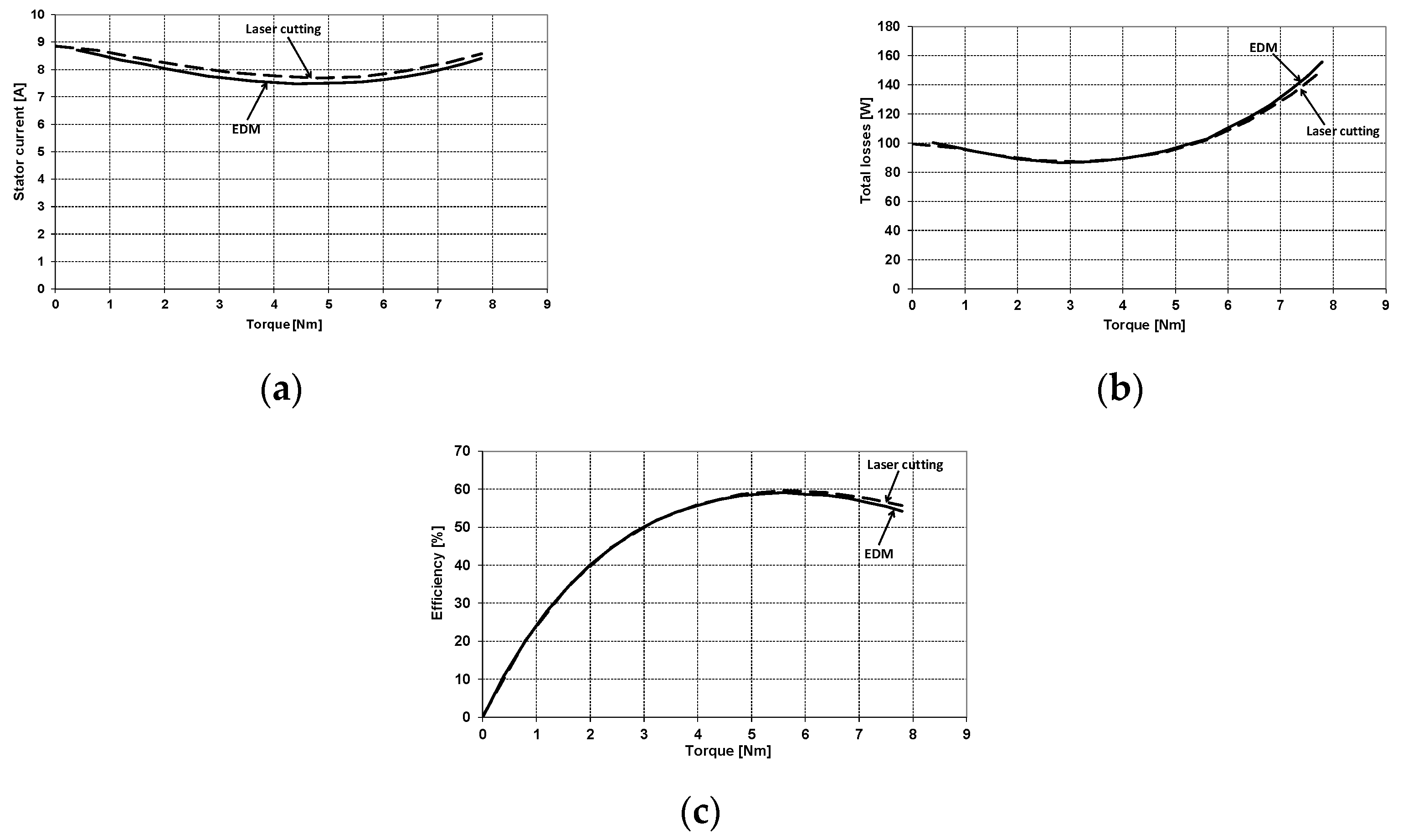
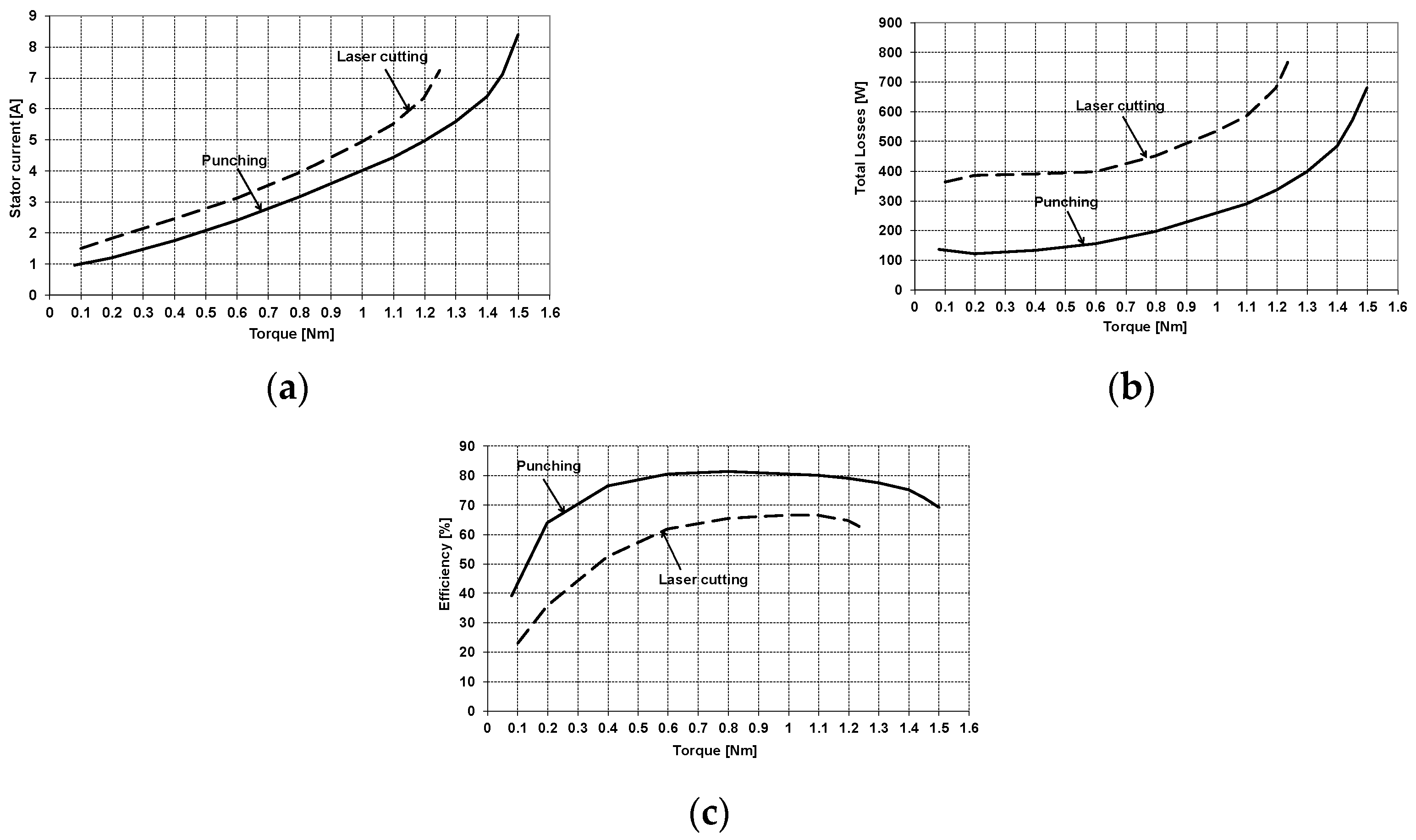
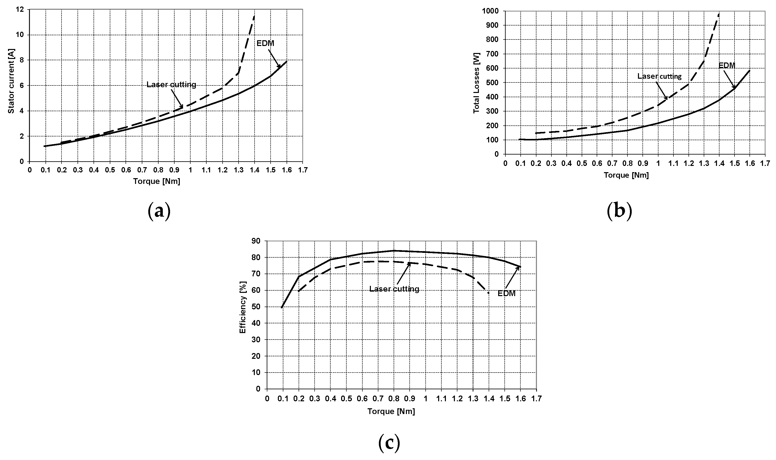
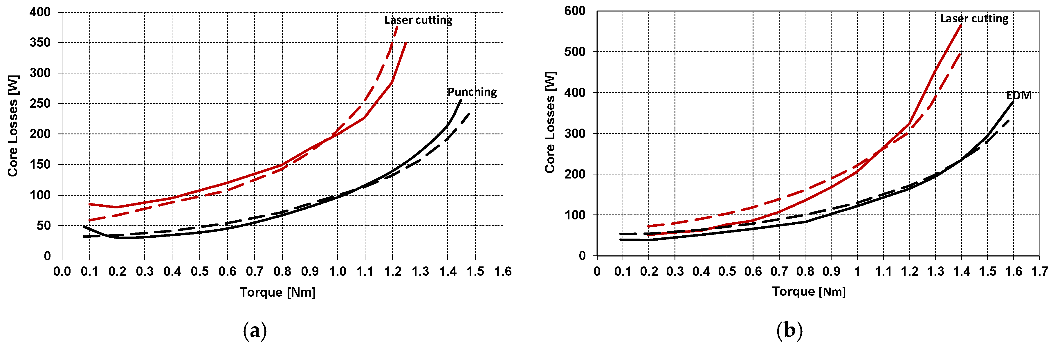
5.3.3. The Load Characteristics of the Investigated Motors for Frequency 350 Hz

Unlike for low frequencies, at a high frequency of the motor supply voltage, the share of losses in the motor core in its total losses is dominant, so in this case the core punching technology has a very large impact on the operational characteristics of the motor. Figure 14 and Table 8 present the load characteristics of motor 1 as a function of shaft torque when powered from the inverter with a voltage of 350 Hz frequency of fundamental harmonic.
In this case, the use of a laser to make core sheet resulted in a very large increase in losses in the core, and as a result also an almost two-fold increase in total losses and a reduction in motor efficiency by more than 20% compared to the parameters of a motor with a core made using mechanical punching for virtually the entire motor load range.
Similar characteristics have been presented for motor 2 in Figure 15 and Table 9. In this case, also the use of a laser for cutting core caused an increase in core losses and total losses, especially when the motor load increased in relation to the values obtained for a motor with a core made with EDM machine, however, these differences are much smaller than in the previous case. This is the result of a change in motor design.
In summation, it can be stated that when developing new motor designs requiring the construction and testing of model motors for which mechanical punching dies are not yet made, it is much more beneficial to use core punching technology using an EDM machine than a simpler to use laser, because then the results will be similar to the characteristics obtained for final implementation of motor with cores cut using mechanical punching.

6. Including the Impact of Core Fabrication Technology in Analytical Calculations of Motor Parameters

When developing new constructions of induction motors, it is necessary at the design stage to calculate operating parameters and characteristics as close as possible to those obtained as a result of measurements on model and prototype motors built up subsequently. At this stage, most often no mechanical punching dies are available to make the core, so other technologies must be used to cut metal sheets. Each of these technologies differently degrades the properties of the metal sheet and, as a result, changes its magnetization characteristics and specific losses in relation to the producers’ characteristics. The determination of such characteristics requires complex tests, therefore another approximate method should be sought to enable calculations of the parameters and characteristics of the designed motors as close as possible to the values obtained as a result of laboratory tests of model motors. This particularly applies to the accuracy of calculating losses in the motor core and magnetizing current [35,36]. As demonstrated in [37], at motor load, core losses due to higher harmonics of induction far outweigh basic losses in teeth and stator yoke. These losses, occur on the surface of the stator and rotor teeth (these are so-called surface losses) and within the stator teeth (pulsating losses), can be divided into surface losses and pulsating losses. The “surface” and pulsating losses in the stator under no-load condition are caused entirely by the permeance rotor harmonics resulting from the effects of rotor slotting on the fundamental harmonic of order p (the rotor harmonics are of order p + jQr, j = ± 1, ± 2, ...) and on the higher slotting harmonics of the stator (which generate rotor harmonics of the order νs + jQr, j = ± 1, ± 2, ..., where νs is the order of permeance harmonics of the stator) [38]. Additional surface losses in the stator and rotor teeth, caused by the stator (rotor) flux density harmonic of rank νs (r), were calculated and modified by the authors in relation to the commonly used method proposed by Taegen [39], and completely based on the measured core losses and predicted according to the relation (1) specific core losses for all individual harmonics of the stator and the rotor fields [37]. Individual loss harmonics are calculated as the product of the specific loss, approximated on the basis of measurement results, for the actual value of the harmonic induction and the corresponding frequency [40] and the mass of the surface layer of the stator and rotor teeth into which the field of individual harmonics penetrates.
P s ( r ) , ν s u r f r ( s ) = w F e ( B r ( s ) , ν r ( s ) , f ν r ( s ) ) ρ F e S s ( r ) λ s ( r ) , ν r ( s )
S s ( r ) = π D s i ( r e ) k t s ( r ) L s ( r ) k F e ;               k t s ( r ) = t s ( r ) b s ( r ) t s ( r ) ;         λ s ( r ) , ν r ( s ) = π D s i ( r e ) 2 | ν r ( s ) |   ;             t s ( r ) = π D s i ( r e ) Q s ( r )
where: P s ( r ) , ν r ( s ) s u r f additional surface losses in the stator (rotor), caused by the ν r ( s ) —rotor (stator) harmonic, B s ( r ) , ν s ( r ) —peak value of the stator (rotor) flux density on the stator (rotor) surface due to the ν s ( r ) — harmonic, b s ( r ) —width of the stator (rotor) slot opening, D s i —internal diameter of the stator core, D r e — external diameter of the rotor core, Q s , r —number of stator (rotor) slots, L s ( r ) –ength of stator (rotor) core, k F e —packing factor of the core, ν s ( r ) —rank of the stator (rotor) harmonic component, ρ F e —mass density of the core material, f ν s ( r ) –frequency of the ν s ( r ) stator (rotor) harmonic field, w F e —specific iron losses for f ν s ( r ) and B s ( r ) , ν s ( r ) , λ s ( r ) , ν s ( r ) —flux penetration depth of the ν s ( r ) harmonic for the stator (rotor) tooth head.
Total additional surface losses in the stator or rotor teeth, being the sum of losses generated by individual harmonics of induction, were calculated from the equations:
P s ( r ) s u r f = ν r ( s ) P s ( r ) , ν r ( s ) s u r f
Accurate consideration of the impact of core punching technology on these losses would require determination, based on metallurgical results, of changed sheet material characteristics and calculations for these characteristics. However, the work proposes an approximate, verified by measurement method for both motors cores cut with a laser and EDM.
The deterioration of magnetic properties caused by core punching technology can be mapped in an approximate way, increasing the depth of penetration of individual harmonics of the field into the tips of the stator and rotor teeth, as the frequency of the supply voltage increases. In the frequency range from 50 to 350 Hz, the calculation results were similar to the results of measurements with increasing the penetration depth when cutting the core with a laser from 1 to 2, while with EDM cutting—from 1 to 1.2. This method was used to calculate losses in the motor 1 core cut with a laser and in the core of the motor 2 cut with a laser and with the use of EDM. The comparison of measured and calculated losses in the core of motor 1 made with the use of a punch and a laser is shown in Figure 16a, and in the core of motor 2 made with the use of EDM and a laser is shown in Figure 16b. All calculations were made for the loss characteristics of electrical sheets measured in a wide frequency range (from 10 to 2000 Hz) and the largest induction possible at a given frequency for 400/420 mm toroidal samples.
The differences in measured and calculated core losses, especially visible when using laser cutting technology, result from the fact that, according to the proposed method, the calculations were carried out assuming that the depth of field penetration into the tooth heads was doubled when laser cutting and about 10% greater when cutting using EDM technology, in relation to the value resulting from Equation (2). Although this assumption gives calculation results approximate to the measured values, they can be both slightly larger and slightly smaller than the measurement results, but at the same time the error of this approximation is relatively small.

7. Conclusions

The method of cutting out induction motor core sheets has a significant impact on the operating parameters obtained, especially core losses and magnetizing current, and thus on motor efficiency, which is so important from the point of view of environmental impact. All cutting methods have an impact on the degradation of the material properties of the core, however, as can be seen from the results cited, laser cutting, quite commonly used especially for small series, can cause a significant deterioration in properties compared to mechanical cutting. This is particularly important for motors operating at higher frequencies.
It is also important that these losses are clearly visible only when the motor is under load, therefore no-load tests may not detect this phenomenon.
The proposed method of measuring magnetic properties and losses on toroidal samples with a width corresponding to the average width of the elements of the magnetic circuit of motors in combination with a modified analytical method allows the calculation of motor parameters taking into account the impact of punching technology.

Author Contributions

Conceptualization, M.D. and K.K.; methodology, M.D. and K.K.; software, M.D. and J.S.; validation, J.S. and W.K.; formal analysis, M.D. and K.K.; investigation, J.S. and W.K.; resources, M.D.; data curation, M.D. and K.K.; writing—original draft preparation, M.D. and K.K.; writing—review and editing, M.D. and K.K.; supervision, M.D. and K.K.; project administration, M.D.; funding acquisition, M.D. All authors have read and agreed to the published version of the manuscript.

Funding

The work is carried out within the framework of the research project POIR.04.01.04-00-0002/16, “Developing a new optimized from the point of view of power loss design high speed three phase induction motors used in industrial drives”, financed by NCBiR within the Operational Program Intelligent Development 2014–2020.

Conflicts of Interest

The authors declare no conflict of interest.

References

  1. Hofmann, M.; Naumoski, H.; Herr, U.; Herzog, H.-G. Magnetic properties of electrical steel sheets in respect of cutting: Micromagnetic analysis and macromagnetic modeling. IEEE Trans. Magn. 2016, 52, 1–14. [Google Scholar] [CrossRef]
  2. Nemoianu, I.V.; Paltanea, V.M.; Paltanea, G.; Dascalu, M.I.; Ciuceanu, R.M. Electric motors of large consumer products challenges and trends from the perspective of power efficiency improvement through modern cutting technologies. In Proceedings of the 2019 Zooming Innovation in Consumer Technologies Conference (ZINC), Novi Sad, Serbia, 29–30 May 2019; pp. 76–81. [Google Scholar]
  3. Paltanea, V.M.; Paltanea, G.; Gavrilă, H.; Nemoianu, I.V.; Andrei, P.C. Magnetic properties degradation due to the cutting procedures in the case of electrical steel used in energy efficient electrical machines. In Proceedings of the Electric Vehicles International Conference (EV), Bucharest, Romania, 5–6 October 2017; pp. 1–4. [Google Scholar]
  4. Schoppa, A.; Louis, H.; Pude, F.; Von Rad, C. Influence of abrasive waterjet cutting on the magnetic properties of non-oriented electrical steels. J. Magn. Magn. Mater. 2003, 254, 370–372. [Google Scholar] [CrossRef]
  5. Lee, H.; Park, J.-T. Effect of cut-edge residual stress on magnetic properties in non-oriented electrical steel. IEEE Trans. Magn. 2019, 55, 1–4. [Google Scholar] [CrossRef]
  6. Gmyrek, Z.; Cavagnino, A.; Ferraris, L. Estimation of the magnetic properties of the damaged area resulting from the punching process: Experimental research and FEM modeling. IEEE Trans. Ind. Appl. 2013, 49, 2069–2077. [Google Scholar] [CrossRef]
  7. Breining, P.; Kahveci, A.; Doppelbauer, M. Effects of annealing on magnetic properties of laminated stator cores and efficiency of induction machines. In Proceedings of the 2019 IEEE International Electric Machines & Drives Conference (IEMDC), San Diego, CA, USA, 12–15 May 2019; pp. 1038–1044. [Google Scholar]
  8. IEC 60404-3. Methods of Measurement of the Magnetic Properties of Magnetic Sheet and Strip by Means of a Single Sheet Tester; International Electrotechnical Commission: Geneva, Switzerland, 2010. [Google Scholar]
  9. IEC 60404-2. Methods of Measurement of the Magnetic Properties of Electrical Steel Strip and Sheet by Means of an Epstein Frame; International Electrotechnical Commission: Geneva, Switzerland, 2008. [Google Scholar]
  10. Weiss, H.A.; Tröber, P.; Golle, R.; Steentjes, S.; Leuning, N.; Elfgen, S.; Hameyer, K.; Volk, W. Impact of punching parameter variations on magnetic properties of nongrain-oriented electrical steel. IEEE Trans. Ind. Appl. 2018, 54, 5869–5878. [Google Scholar] [CrossRef]
  11. Goldbeck, G.; Cossale, M.; Kitzberger, M.; Bramerdorfer, G.; Andessner, D.; Amrhein, W. Numerical implementation of local degradation profiles in soft magnetic materials. In Proceedings of the 2018 XIII International Conference on Electrical Machines (ICEM), Alexandroupoli, Greece, 3–6 September 2018; pp. 1037–1043. [Google Scholar]
  12. Kedous-Lebouc, A.; Cornut, B.; Perrier, J.C.; Manfé, P.; Chevalier, T. Punching influence on magnetic properties of the stator teeth of an induction motor. J. Magn. Magn. Mater. 2003, 254–255, 124–126. [Google Scholar] [CrossRef]
  13. Kedous-Lebouc, A.; Messal, O.; Youmssi, A. Joint punching and frequency effects on practical magnetic characteristics of electrical steels for high-speed machines. J. Magn. Magn. Mater. 2017, 426, 658–665. [Google Scholar] [CrossRef]
  14. Schneider, M.; Hubert, M.; Franke, J. Influence of cutting edge on core loss induced through various manufacturing parameters. In Proceedings of the 2016 6th International Electric Drives Production Conference (EDPC), Nuremberg, Germany, 30 November–1 December 2016. [Google Scholar]
  15. Agamloh, E.B.; Cavagnino, A. High efficiency design of induction machines for industrial applications. In Proceedings of the 2013 IEEE Workshop on Electrical Machines Design Control and Diagnosis (WEMDCD), Paris, France, 11–12 March 2013; pp. 33–46. [Google Scholar]
  16. Malinowski, J.; McCormick, J.; Dunn, K. Advances in construction techniques of AC induction motors: Preparation for super-premium efficiency levels. IEEE Trans. Ind. Appl. 2004, 40, 1665–1670. [Google Scholar] [CrossRef]
  17. Bali, M.; DeGersem, H.; Muetze, A. Finite-element modeling of magnetic material degradation due to punching. IEEE Trans. Magn. 2014, 50, 7018404. [Google Scholar] [CrossRef]
  18. Bali, M.; Muetze, A. Modeling the effect of cutting on the magnetic properties of electrical steel sheets. IEEE Trans. Ind. Electron. 2017, 64, 2547–2556. [Google Scholar] [CrossRef]
  19. Arshad, W.; Ryckebusch, T.; Magnussen, F.; Lendenmann, H.; Eriksson, B.; Soulard, J.; Malmros, B. Incorporating lamination processing and component manufacturing in electrical machine design tools. In Proceedings of the 2007 IEEE Industry Applications Annual Meeting, New Orleans, LA, USA, 23–27 September 2007; pp. 94–102. [Google Scholar]
  20. Vandenbossche, L.; Jacobs, S.; Jannot, X.; McClelland, M.; Saint-Michel, J.; Attrazic, E. Iron loss modelling which includes the impact of punching, applied to high efficiency induction machines. In Proceedings of the 3rd International Electric Drives Production Conference (EDPC), Nuremberg, Germany, 29–30 October 2013; pp. 1–10. [Google Scholar]
  21. Bourchas, K.; Stening, A.; Soulard, J.; Broddefalk, A.; Lindenmo, M.; Dahlén, M.; Gyllensten, F. Quantifying effects of cutting and welding on magnetic properties of electrical steels. IEEE Trans. Ind. Appl. 2017, 53, 4269–4278. [Google Scholar] [CrossRef] [Green Version]
  22. Manescu-Paltanea, V.; Paltanea, G.; Nemoianu, I.V. Degradation of Static and Dynamic Magnetic Properties of Non-Oriented Steel Sheets by Cutting. IEEE Trans. Magn. 2018, 54, 1–5. [Google Scholar] [CrossRef]
  23. Gmyrek, Z.; Smółka, K. Efficiency analysis of fractional kilowatt reluctance motors with various frame sizes, taking into account the impact of the punching process. Energies 2020, 13, 357. [Google Scholar] [CrossRef] [Green Version]
  24. Yamazaki, K.; Suzuki, A.; Ohto, M.; Takakura, T. Harmonic loss and torque analysis of high-speed induction motors. IEEE Trans. Ind. Appl. 2012, 48, 933–941. [Google Scholar] [CrossRef]
  25. Morimoto, M.; Inamori, M. Performance improvement of induction motor by press molded SMC core. In Proceedings of the 2013 15th European Conference on Power Electronics and Applications (EPE), Lille, France, 2–6 September 2013; pp. 1–6. [Google Scholar]
  26. Hargrove, S.K.; Ding, D. Determining cutting parameters in wire EDM based on workpiece surface temperature distribution. Int. J. Adv. Manuf. Technol. 2007, 34, 295–299. [Google Scholar] [CrossRef]
  27. Parandoush, P.; Hossain, A. A review of modeling and simulation of laser beam machining. Int. J. Mach. Tools Manuf. 2014, 85, 135–145. [Google Scholar] [CrossRef]
  28. The Ultimate Guide to Fiber Laser Cutting. Available online: https://www.machinemfg.com/fiber-laser-cutting/ (accessed on 28 March 2020).
  29. Paltanea, V.M.; Paltanea, G.; Gavrila, H. Some important effects of the water jet and laser cutting methods on the magnetic properties of the non-oriented silicon iron sheets. In Proceedings of the 2015 9th International Symposium on Advanced Topics in Electrical Engineering (ATEE), Bucharest, Romania, 7–9 May 2015; pp. 452–455. [Google Scholar]
  30. Emura, M.; Landgraf, F.; Ross, W.; Barreta, J. The influence of cutting technique on the magnetic properties of electrical steels. J. Magn. Magn. Mater. 2003, 254–255, 358–360. [Google Scholar] [CrossRef]
  31. Baudouin, P.; Belhadj, A.; Breaban, F.; Deffontaine, A.; Houbaert, Y. Effects of laser and mechanical cutting modes on the magnetic properties of low and medium Si content nonoriented electrical steels. IEEE Trans. Magn. 2002, 38, 3213–3215. [Google Scholar] [CrossRef]
  32. Belhadj, A.; Baudouin, P.; Breaban, F.; Deffontaine, A.; Dewulf, M.; Houbaert, Y. Effect of laser cutting on microstructure and on magnetic properties of grain non oriented electrical steels. J. Magn. Magn. Mater. 2003, 256, 20–31. [Google Scholar] [CrossRef]
  33. Von Pfingsten, G.; Steentjes, S.; Thul, A.; Herold, T.; Hameyer, K. Soft magnetic material degradation due to manufacturing process: A comparison of measurements and numerical simulations. In Proceedings of the 17th International Conference on Electrical Machines and Systems (ICEMS), Hangzhou, China, 22–25 October 2014; pp. 2018–2024. [Google Scholar]
  34. Cao, W. Comparison of IEEE 112 and New IEC Standard 60034-2-1. IEEE Trans. Energy Convers. 2009, 24, 802–808. [Google Scholar]
  35. Kindl, V.; Cermak, R.; Ferkova, Z.; Skala, B. Review of time and space harmonics in multi-phase induction machine. Energies 2020, 13, 496. [Google Scholar] [CrossRef] [Green Version]
  36. Lee, A.C.; Kirtley, C.H.; Huang, J.L.; Wang, Y.; Zhang, H. A hybrid methodology for analyzing the performance of induction motors with efficiency improvement by specific commercial measures. Energies 2019, 12, 4497. [Google Scholar] [CrossRef] [Green Version]
  37. Dems, M.; Komeza, K. The influence of electrical sheet on the core losses at no-load and full-load of small power induction motors. IEEE Trans. Ind. Electron. 2017, 64, 2433–2442. [Google Scholar] [CrossRef]
  38. Komeza, K.; Dems, M. Finite-element and analytical calculations of no-load core losses in energy-saving induction motors. IEEE Trans. Ind. Electron. 2012, 59, 2934–2946. [Google Scholar] [CrossRef]
  39. Taegen, P.F. Surface losses in cage induction motors. In Proceedings of the Beijing International Conference on Electrical Machines, Beijing, China, 10–14 August 1987; pp. 326–329. [Google Scholar]
  40. Dems, M.; Komeza, K.; Lecointe, J.-P. Variation of additional losses at no-load and full-load for a wide range of rated power induction motors. Electr. Power Syst. Res. 2017, 143, 692–702. [Google Scholar] [CrossRef]
Figure 1. Basic dimension of the toroidal sample.
Energies 13 01960 g001
Figure 2. Toroidal samples—420 mm (a) and 120 mm (b), with electromotive force (EMF) measurement (a) and excitation windings (b).
Energies 13 01960 g002
Figure 3. (a) BH curves for M270-35A electrical steel sheet; (b) Specific losses versus magnetic flux density for M270-35A electrical steel sheet; (c) BH curves for M470-50A electrical steel; and (d) Specific losses versus magnetic flux density, for M470-50 A electrical steel sheet. All curves for 2 different toroidal samples; solid line—toroidal sample 400/420 mm and dashed line—toroidal sample 70/120 mm.
Energies 13 01960 g003
Figure 4. The shape of stator and rotor core for motor 1. (a)—whole, (b)—enlarged fragment.
Energies 13 01960 g004
Figure 5. The shape of stator and rotor core for motor 2. (a)—whole, (b)—enlarged fragment.
Energies 13 01960 g005
Figure 6. Measurement circuit (a) and a screenshot of the dedicated software (b): 1—resistance measurement relay switch, 2—battery supply for resistance measurement, 3—current transducer for resistance measurement, 4—resistance measurement manual switch, 5—voltage transducer for resistance measurement, 6—supply (induction regulator/solid state converter), 7—main switch, 8—current transducers, 9—tested motor, 10—measurement signals junction boxes, 11—hysteresis dynamometer, 12—dynamometer (torque) control system, 13—thermocouples with dedicated data loggers, 14—resistive voltage divider, and 15—computer based measurement system.
Energies 13 01960 g006
Figure 7. Overall view on the measurement stand: 1—tested motor, 2—hysteresis dynamometer, 3—dynamometer (torque) control system, 4—computer based measurement system, 5—current transducers, 6—resistive voltage divider, and 7—temperature data loggers.
Energies 13 01960 g007
Figure 8. No-load characteristics for motor 1 with mains voltage of 50 Hz: (a) No-load stator current variation with voltage; (b) No-load total losses, copper losses, and core losses variation with voltage; solid line—punching and dashed line—laser cutting.
Energies 13 01960 g008
Figure 9. No-load characteristics for motor 2 with mains voltage of 50 Hz: (a) No-load stator current variation with voltage; (b) No-load total losses, copper losses, and core losses variation with voltage; solid line—EDM and dashed line—laser cutting.
Energies 13 01960 g009
Figure 10. The load characteristics for motor 1 fed from inverter with voltage frequency of 10 Hz: (a) stator current variation with torque; (b) total losses variation with torque; and (c) efficiency variation with torque.
Energies 13 01960 g010
Figure 11. The load characteristics for motor 2 fed from inverter with voltage frequency of 10 Hz: (a) stator current variation with torque; (b) total losses variation with torque; and (c) efficiency variation with torque.
Energies 13 01960 g011
Figure 12. The load characteristics for motor 1 fed from inverter with voltage frequency of 20 Hz: (a) stator current variation with torque; (b) total losses variation with torque; and (c) efficiency variation with torque.
Energies 13 01960 g012
Figure 13. The load characteristics for motor 2 fed from inverter with voltage frequency of 20 Hz: (a) stator current variation with torque; (b) total losses variation with torque; and (c) efficiency variation with torque.
Energies 13 01960 g013
Figure 14. The load characteristics for motor 1 fed from inverter with voltage frequency of 350 Hz: (a) stator current variation with torque; (b) total losses variation with torque; and (c) efficiency variation with torque.
Energies 13 01960 g014
Figure 15. The load characteristics for motor 2 fed from inverter with voltage frequency of 350 Hz: (a) stator current variation with torque; (b) total losses variation with torque; and (c) efficiency variation with torque.
Energies 13 01960 g015
Figure 16. Measured and calculated, using analytical method described above, losses in the cores of both motors made using different technologies at a frequency of supply voltage 350 Hz: (a) motor1; (b) motor 2; solid line—measured results and dashed line—calculated results.
Energies 13 01960 g016
Table 1. Material parameters of the electrical steel sheets M270-35A.
Parameter0.2 T0.6 T1.0 T1.4 T1.8 T
Toroidal Sample 400/420 mm
Magnetic field strength (A/m)7618433290411,420
Specific losses (W/kg)–50 Hz0.140.751.522.685.33
Specific losses (W/kg)–350 Hz1.529.4020.9739.34
Specific losses (W/kg)–1000 Hz6.6444.76
Toroidal Sample 70/120 mm
Magnetic field strength (A/m)378317066611,537
Specific losses (W/kg)–50 Hz0.080.511.182.295.34
Specific losses (W/kg)–350 Hz1.037.0917.2033.65
Specific losses (W/kg)–1000 Hz4.7334.7190.46
Table 2. Material parameters of the electrical steel sheets M470-50A.
Parameter0.2 T0.6 T1.0 T1.4 T1.8 T
Toroidal Sample 400/420 mm
Magnetic field strength (A/m)8218834077310,758
Specific losses (W/kg)–50 Hz0.160.911.903.246.02
Specific losses (W/kg)–350 Hz1.9613.0431.0357.35
Specific losses (W/kg)–1000 Hz9.1366.38
Toroidal Sample 70/120 mm
Magnetic field strength (A/m)419119861911,491
Specific losses (W/kg)–50 Hz0.110.681.592.915.85
Specific losses (W/kg)–350 Hz1.4810.9428.3755.27
Specific losses (W/kg)–1000 Hz7.2656.18
Table 3. The basic design data for investigated motors.
ParameterMotor 1Motor 2
the height from the base to the shaft end centre (mm)7190
stator external diameter (mm)120135
stator internal diameter (mm)7877
the length of the stator core (mm)120120
air gap length (mm)0.2250.3
number of stator slots (-)3624
number of rotor slots (-)3230
number of turns of stator winding (-)11496
core materialM470-50AM270-35A
Table 4. Load test results for motor 1 at 10 Hz.
Parameter0 Nm2.0 Nm4.0 Nm6.0 Nm7.8 Nm
Punching
Output power (W)0.359.6112.0153.0170.5
Stator current (A)8.507.486.666.397.19
Copper losses (W)211.8163.3128.3117.5147.4
Core losses (W)10.99.59.69.311.3
Total losses (W)223.7177.0152.5163.3234.1
Efficiency (%)0.125.242.448.442.1
Laser Cutting
Output power (W)0.459.4112.0154.4174.2
Stator current (A)9.418.437.466.937.32
Copper losses (W)239.0194.2153.2133.1150.1
Core losses (W)10.810.88.79.19.1
Total losses (W)250.7209.3176.4177.1230.8
Efficiency (%)0.222.138.846.643.0
Table 5. Load test results for motor 2 at 10 Hz.
Parameter0 Nm2.0 Nm4.0 Nm6.0 Nm7.8 Nm
EDM
Output power (W)0.359.7112.8157.2185.1
Stator current (A)8.568.037.537.638.41
Copper losses (W)71.874.068.771.385.2
Core losses (W)24.511.37.27.310.2
Total losses (W)97.189.289.5110.7156.0
Efficiency (%)0.340.155.858.754.3
Laser Cutting
Output power (W)0.560.0113.8159.0189.2
Stator current (A)8.858.257.767.848.57
Copper losses (W)88.677.468.770.384.3
Core losses (W)10.49.08.48.39.7
Total losses (W)99.489.689.5108.5150.3
Efficiency (%)0.540.156.059.455.7
Table 6. Load test results for motor 1 at 20 Hz.
Parameter0 Nm2.0 Nm4.0 Nm6.0 Nm7.8 Nm
Punching
Output power (W)0.7122.2237.1342.2425.5
Stator current (A)7.196.526.306.517.23
Copper losses (W)150.5122.8114.2121.5148.7
Core losses (W)20.820.119.319.522.1
Total losses (W)173.3148.3149.7177.7237.1
Efficiency (%)0.445.261.365.864.2
Laser Cutting
Output power (W)0.7122.0237.0343.2427.8
Stator current (A)8.267.446.997.037.53
Copper losses (W)184.4150.8134.2136.6158.5
Core losses (W)24.020.920.419.219.5
Total losses (W)209.0176.2170.2191.4242.6
Efficiency (%)0.440.958.264.263.8
Table 7. Load test results for motor 2 at 20 Hz.
Parameter0 Nm2.0 Nm4.0 Nm6.0 Nm7.8 Nm
EDM
Output power (W)0.8122.3238.1345.8434.5
Stator current (A)7.417.167.207.708.55
Copper losses (W)64.460.361.170.186.7
Core losses (W)21.420.320.622.125.3
Total losses (W)87.485.596.4124.8169.0
Efficiency (%)0.958.971.273.572.0
Laser Cutting
Output power (W)0.9122.5238.9347.7437.4
Stator current (A) 7.667.317.407.898.73
Copper losses (W) 66.360.862.371.287.4
Core losses (W)21.220.020.321.324.4
Total losses (W)88.585.096.1122.9165.5
Efficiency (%)1.159.071.373.972.6
Table 8. Load test results for motor 1 at 350 Hz.
Parameter0.1 Nm0.4 Nm0.8 Nm1.1 Nm1.2 Nm
Punching
Output power (W)88.6434.7862.21174.61275.9
Stator current (A) 0.981.763.174.454.96
Stator losses (W) 2.78.728.355.869.7
Core losses (W) 47.934.767.0115.7139.1
Mechanical losses (W)86.285.484.082.782.1
Total losses (W) 137.3133.5197.2290.5336.1
Efficiency (%)39.276.581.480.279.2
Laser Cutting
Output power (W)109.6431.6856.81162.91257.1
Stator current (A) 1.502.463.955.516.36
Stator losses (W) 6.116.542.683.2111.0
Core losses (W)270.5282.9301.7373.1426.6
Mechanical losses (W)85.684.783.381.680.4
Total losses (W)363.6391.1450.7584.8681.0
Efficiency (%)23.252.565.566.564.9
Table 9. Load test results for motor 2 at 350 Hz.
Parameter0.1 Nm0.4 Nm0.8 Nm1.0 Nm1.3 Nm
EDM
Output power (W)100.6436.1868.01080.81394.6
Stator current (A) 1.211.933.173.955.35
Stator losses (W) 1.74.411.818.333.8
Core losses (W) 39.950.783.3121.7193.5
Mechanical losses (W)60.760.259.458.957.9
Total losses (W) 102.7118.4165.9217.6320.6
Efficiency (%)49.578.784.083.281.3
Laser Cutting
Output power (W)111.9436.2865.61077.21377.1
Stator current (A) 1.312.033.514.506.98
Stator losses (W) 1.94.713.922.955.2
Core losses (W) 43.761.8135.1205.2452.2
Mechanical losses (W)93.092.391.090.287.3
Total losses (W) 139.2162.3253.6340.9649.3
Efficiency (%)44.672.977.376.068.0

