1. Introduction
The joint design and integrated operation of electrical distribution grids and district heating systems promises to exploit hitherto unused synergies for increasing efficiency and flexibility. The envisaged goal is to achieve an increase of the hosting capability of electrical distribution networks for renewable energy sources (RES), while simultaneously reducing greenhouse gas emissions and primary energy use of district heating systems. For instance, in electrical distribution grids, the integration of photovoltaic (PV) and wind generation into the existing infrastructure has severe consequences on the power quality. At the same time, district heating networks struggle to replace carbon intensive heat plants with economically feasible combined heat and power plants and other renewable heat sources. In case network planning and operation are done appropriately, the diverse storage technologies, the different time constants and the diverse constraints regarding demand and generation can complement each other.
However, there is a lack of tools and methods for designing such integrated energy systems, especially in view of a detailed validation of proposed control and operation schemes. The work presented here introduces a design approach that addresses the technical challenges of both domains at the same time, including their dynamic interaction at network level as well as local and high-level control (see
Figure 1). This enables the exploitation of synergies in the operation of hybrid thermal-electrical distribution system in an optimal way. The presented approach relies on co-simulation, which enables the coupling of domain-specific simulators and multi-purpose tools in a way that allows to combine multi-physics simulations and optimization procedures. This approach is motivated by the criteria established in
Section 2, and backed up by reviewing the available tools and methods according to the state-of-the-art for simulation and optimization (
Section 3). A description of the modeling approach and the utilized simulation tools is presented in
Section 4. Based on this, a novel methodology is presented in
Section 5 that links design constraints to suitable operational strategies and optimization methods. Finally, the applicability of the presented approach is demonstrated in two real-world applications in
Section 6.
Scope and Main Contributions
This paper aims at developing an integrated optimal design and control framework for coupled district heating and electrical distribution networks, extending the scope of traditional design tools for multi-energy systems. The simulation and optimization framework is illustrated for designing storage and thermal-electric appliances in two case studies, i.e., an industrial and a rural area. Note that the focus of this work lies on the methodological contribution rather than on the case study results. Compared to existing studies, this work explicitly includes detailed models for the district heating network, the electric distribution grid as well as low- and high-level control implementations already in the design stage. Thus, the method considers the impact of different levels of control and operation on the optimal system design. The coupling of heterogeneous modeling paradigms and tools is established via a co-simulation approach and the design optimization relies on the use of meta-heuristics.
This work addresses experts with backgrounds in district heating, electric distribution, energy storage deployment, control theory, design optimization and (co-)simulation alike. The multi-disciplinary nature of the proposed design approach (see also
Figure 1) requires a comprehensive introduction and presentation of the work to make it understandable and useful for readers and experts coming from these different fields.
In summary, this paper contributes to the research field by presenting a simulation-based design optimization approach that: (i) is based on a fully dynamic thermal-hydraulic district heating and electrical distribution network model; and (ii) explicitly includes closed-loop control implementations and, thus, leads to the optimal design being dependent on operational aspects. The method is used in two case studies that exhibit different control complexities, i.e., model predictive and rule-based, and design spaces, i.e., a finite set of allowed solutions and an infinite set of possible designs.
2. Prerequisites for the Design Optimization of Hybrid Distribution Systems
2.1. Determining Factors of Hybrid Distribution Systems
Hybrid networks are realized through the physical interconnection and joint operation of electrical and thermal distribution grids. From a technical perspective, this is accomplished with the help of coupling points, i.e., devices which directly or indirectly enable the exchange of energy across carrier domains. For the proposed design approach, a (preliminary) technical system layout for both the electrical network and the thermal network topology is required from the domain experts, which already includes the type and position of the coupling point(s). The considered degrees of freedom in this work are typically related to the sizing of components (e.g., storage capacities or power ratings) or controller set-points (e.g., gains or thresholds). A specific technical system layout together with a specific set of numerical values for theses degrees of freedom is referred to as system configuration in this work.
The proposed design optimization approach explicitly considers operational and control aspects at different levels. In general, there are control systems at the process level (e.g., for heat pumps or transformers) that are designed to ensure that objectives are achieved locally (e.g., valve positions and tap changer). However, the complexity of control schemes increases drastically when individual processes are combined to larger systems and new (common) control/optimization targets are defined. In such a case, a higher-level control instance—referred to as
operational strategy in this work—is required that governs the local processes in compliance with relevant system constraints (compare with
Figure 2).
2.2. Key Prerequisites and Modeling Requirements
This work focuses on the optimization of technical design aspects, assessing the impact of system configurations and operational strategies on the system’s performance. This requires not only the quantification of performance indicators on the system level, but also validation down to the component level, in order to avoid infeasible results. Hence, any valid design approach for hybrid thermal-electrical distribution networks has to fulfill the
key prerequisites (KP) presented in
Table 1.
In general, the most viable approaches in this context are simulation-based methods, as they allow the qualitative and quantitative examination of new concepts in a comparably fast and inexpensive way before deployment. However, the accurate and detailed modeling of all involved networks including their coupling points and control is of utmost importance. When deployed in a joint simulation, the (sub-)models representing the individual domains have to comply with the
modeling requirements (MR) presented in
Table 1.
It should be noted that some of the criteria defined above do not necessarily apply for design optimization approaches focusing on socioeconomic goals, especially regarding the required level of detail (spatial and temporal).
3. State of the Art Regarding the Simulation and Optimization of Hybrid Distribution Systems
3.1. Simulation of Coupled Heat and Power Networks
Previous work on multi-carrier energy systems was mainly focused on determining an optimal mix of energy sources as well as conversion and storage technologies. Comprehensive overviews were given by Mancarella et al. [
1] and van Beuzekom et al. [
2], who independently concluded that existing approaches are not suited for detailed technical assessments that are required for network infrastructure planning and operation. Consequently, they argued that there is a need for new tools and methods in this regard. One of the main reasons is that established tools for system design, such as EnergyPLAN [
3] or HOMER [
4], do not offer models that are detailed enough to evaluate the effects of local controls on the process level, thus disagreeing with KP1, MR2 and MR3. Unfortunately, simulation tools that focus on the technical evaluation of energy systems on the process level are by themselves also not suited in this context [
5], as they are typically concerned with just a single energy-related domain. Anything outside their direct focus is usually taken into account only implicitly or using simplified models, thus disagreeing with KP1, MR1, MR2 and MR3.
A potential solution is provided by multi-domain modeling languages. For instance, there exist several libraries for the Modelica [
6] language that target energy-related domains, such as power systems [
7,
8] or buildings [
9], which in combination allow the modeling of hybrid thermal-electrical distribution systems (and thus satisfying KP1 and MR1). It has also been demonstrated how such models can be utilized for standard optimization approaches (satisfying KP2), see for instance [
10]. However, domain experts (thermal, electrical, controls) are often not trained to use such tools, which is complicating compliance with KP3. Furthermore, since Modelica focuses on modeling physical systems, the implementation of controls and operational strategies with a high algorithmic effort, e.g., model predictive control, can become difficult, thus complicating compliance with MR3. Most of the above arguments are also valid for similar languages and tools, e.g., MATLAB/Simulink/Simscape [
11]. Hence, in the context of simulating hybrid thermal-electrical distribution networks, the usability of approaches relying exclusively on multi-domain modeling languages is in practice (still) limited, or at least the associated effort is (still) considerably high.
An alternative solution is offered by co-simulation approaches, which overcome these limitations by enabling the coupling of domain-specific simulators and multi-purpose tools (thus satisfying MR2 and MR3). This allows domain experts to use the most appropriate tools according to the state of the art for their respective domain, including advanced optimal control schemes. On the one hand, this guarantees an adequate and precise representation of the individual domains (thus satisfying KP1 and MR1) [
12]. On the other hand, it facilitates the participation of and interaction between experts from different domains, whose expertise is often closely linked to specific tools (thus satisfying KP3). This advantage has led to various research activities in many energy-related domains, e.g., buildings [
13,
14], power systems [
15,
16,
17,
18] and hybrid distribution networks [
12,
19].
Given these considerations, co-simulation has been chosen to analyze systems according to the criteria defined in
Section 2 for the work presented here. Even though other approaches—and especially approaches based on multi-domain modeling languages—are expected to become mature and flexible enough in the future, the advantages of coupling domain-specific simulators and multi-purpose tools in a co-simulation still prevail.
Within this context, established tools for the design and optimization of multi-energy systems can be considered as important guides for an overall design process, as their results should be used as starting point for a detailed technical evaluation.
3.2. Design Optimization of Coupled Heat and Power Networks
Available literature on design optimization of hybrid thermal-electric networks is mainly based on the energy hub concept introduced by Geidl et al. [
20]. Related work focuses on determining optimal design of energy hubs such as selection and sizing of coupling units and storages [
21]. However, applied models rely on many simplifications and are not able to cover technical aspects relevant in power networks (e.g., voltages and reactive power), in district heating (e.g., temperature propagation and pressures), and also in individual components (e.g., temperature stratification in thermal storages). Thus, such an approach contradicts the identified modeling requirements MR2 as well as MR3.
One possible solution, targeted in this paper, is to utilize detailed (co-)simulation setups for design optimization. Even though simulations are very well suited to characterize a given system design using a system performance measure, their application in the context of design optimization is more challenging. From a mathematical programming point-of-view, the simulation-based design leads to objective functions that must, in general, be considered non-linear, multi-modal and discontinuous [
22]. To make matters more complicated, the evaluation of the objective function is computationally expensive (minutes to hours or even days per evaluation), depending on the complexity of the simulation model. With the number of possible design variables being high and the range of corresponding input parameter values being huge or even infinite, it becomes infeasible to perform this search by hand or by brute-force. Thus, this problem class requires to either reduce the allowed solution space and/or to use efficient black-box optimization algorithms, where finding a global optimum within finite time is not guaranteed [
23].
Nevertheless, simulation-based design optimization is a frequently used technique as it allows the use of detailed models. The possibility to use high-fidelity models for optimization is especially relevant when targeting systems-of-systems, such as hybrid thermal-electric networks in this work, and, thus, satisfies KP2. In energy-related research, applications to building design are most frequent. The dynamic simulation tool IDA ICE together with a multi-objective optimization was used to find cost-optimal energy performance renovation measures for educational buildings by Niemela et al. [
24]. Delgarm et al. [
25] used the building energy simulation program EnergyPlus and a multi-objective particle swarm optimization to find the building specifications that minimize annual energy consumption. Many more similar studies exist and Nguyen et al. [
26] provided an extensive summary of building related simulation-based optimization methods. Recent work uses simulation-based optimization in the context of district heating system design. Wang et al. [
27] optimized the hydraulic design of variable-speed pumps in multi-source district heating networks using static hydraulic simulation and a genetic optimizer. Van der Heijde et al. [
28] tried to find the cost optimal location and size of thermal storage tanks in district heating networks using dynamic thermal-hydraulic simulation combined with optimal control and a genetic multi-objective optimization algorithm.
3.3. Summary and Conclusion Regarding the Relevant State of the Art
Based on the review of the relevant state of the art above, it follows that established optimization models do not provide the level of detail required for assessing hybrid thermal-electrical distribution grids, especially in view of closed-loop control and operation. In practice, currently only the co-simulation of domain-specific technical models can provide the desired degree of accuracy. However, even though these technical models are commonly used by domain experts for detailed assessments, they are typically not designed nor intended to be used for optimization. The literature gives examples of how co-simulation and this class of technical models can be used for optimization, but there exists—to best knowledge of the authors—no general methodology to support this process.
In this context, this work is the first to introduce simulation-based optimization for coupled district heating and electric network simulation combined with closed-loop control. A methodology to assist the co-simulation-based design of coupled heat and power networks is presented by providing conceptual guidance and a proof-of-concept implementation to the above mentioned problem setting. The focus lies on the utilized technical models (see
Section 4) and their integration into suitable optimization approaches (see
Section 5), not on the formulation of specific optimization algorithms.
Table 2 summarizes this situation in terms of the KPs and MRs identified above (+, full compliance; ∘, compliance with effort; −, insufficient compliance).
4. Simulation Approach for Hybrid Networks
This section presents the approach used in this work for the detailed simulation of coupled heat and power networks including control. The overall model is highly complex, exhibits non-linear behavior and has no closed algebraic formulation. On the one hand, this rules out the utilization of the most commonly used optimization approaches (e.g., LP or MILP). On the other hand, this additional complexity is unavoidable for analyzing the technical details of control and operation in such networks. In view of the general optimization methodology presented in
Section 5, the presented approach can be regarded as a representative example of co-simulation approaches used for technical assessments. As such, it highlights the differences between the class of simulation models targeted by this work and the class of models typically used for optimization.
4.1. Co-Simulation Environment
A co-simulation approach enables the coupling of the different modeling paradigms, i.e., a transient thermal-hydraulic model, a quasi-static power flow model and time-discrete advanced control models. Thus, the influence of time-discrete
advanced control systems, e.g., using rule-based control or model predictive control (MPC), on the dynamic
physical system, i.e., the electric and the district heating (DH) network including supplies, coupling units and consumers, can be studied. This enables the assessment of hybrid thermal-electrical distribution grids with appropriate spatial and temporal resolution for relevant use cases [
12].
The modeling activities and environments used in this work are split into the control model and the physical system model, with the latter only including low-level control, e.g., PID controllers. The assessment method is based on modeling tools according to the state of the art for each domain that are presented in more detail in the following sections.
Within the context of this work, the FUMOLA environment [
29] has been used as co-simulation environment. FUMOLA is specifically designed to support the features offered by the Functional Mock-up Interface (FMI) specification [
30], which defines a standardized application programming interface (API) and model description for both co-simulation and model exchange. FMI was selected as it is a mature, non-proprietary specification, developed by both academia and industry. The FMI standard enables the exchange and extension of tools and methods for the different domains and, thus, makes the approach highly versatile and extensible, especially in selecting the most appropriate method for advanced control system implementation.
4.2. District Heating Network Model
Thermal networks (including producers, network, thermal storages and consumers) are modeled in Modelica/Dymola [
6,
31] with the help of the DisHeatLib library [
32] that is built upon the IBPSA library [
33]. These open-source libraries include models for the most relevant components of district heating networks, considering bi-directional mass flows, heat transport delays, detailed substation and storage models and other thermo-hydraulic aspects that are highly relevant in heat networks. In addition, it provides models of local controllers and interfaces to electric networks. In summary, this modeling approach captures transient thermal and quasi-static hydraulic network behavior. The most relevant models are shortly presented in the following.
All DH pipes are modeled using a plug flow approach. The outlet temperature
and, thus, the heat loss of a fluid parcel passing a pipe is described as:
It depends only on the initial temperature
, residence time
, undisturbed ground temperature
calculated using the Kusuda equation [
34], thermal resistance of the pipe
R and heat capacity of the water in the pipe
C. The pressure drop mass flow correlation along the pipe is given by
where
k is the constant flow coefficient calculated for nominal conditions using the Colebrook equation for turbulent flow in rough pipes [
35]. Details about implementation and experimental validation can be found in [
36]. Heat exchangers in the DH substations are modeled with a variable effectiveness using a number of transfer units approach [
37]. Valves are modeled using the above pressure drop and flow rate correlation with the flow coefficient
k depending on the opening control signal.
Thermal energy storages are modeled using a vertically discretized multi-node approach to account for stratification and buoyancy [
38]. Heat pumps are modeled using a Carnot-efficiency-based approach, electric heaters use a constant efficiency and gas and biomass boilers as well as combined heat and power (CHPs) use heat generation dependent efficiencies. The main district heating supply unit is modeled as an ideal heat and differential pressure source and with no limits on maximum/minimum power or ramp rate. A fixed supply temperature is assumed for all generators.
A full list of model formulations and implementations can be found in the open-source Modelica libraries DisHeatLib and IBPSA.
4.3. Electrical Distribution Grid Model
Electrical distribution grids (including producers and consumers) are modeled with DIgSILENT PowerFactory [
39], an engineering tool targeting primarily professional users. The quasi-static assessment of the electrical networks covers the most important features, such as voltage fluctuations and time-varying loads and generation. DIgSILENT PowerFactory’s simulation interface has been extended to enable a series of consecutive power flow calculations in a co-simulation [
40].
The power flow equations for node
a in an
N-node system are given in complex form:
where
and
denote the complex conjugate apparent power and voltage at node
a, respectively,
denotes the bus admittance matrix and
denotes the complex voltage at node
b. This results to
equations for the
unknowns, i.e., voltage, active/reactive power and voltage angle.
Coupling units are modeled as PQ buses, where active and reactive power is known, using the average power consumption/generation from the dynamic DH network model over the synchronization interval as input. Transformer units connect the low-voltage electrical networks to an external grid, i.e., modeled as a slack bus that determines the voltage and phase at the connection point.
4.4. Operation and Control Models
General-purpose tools such as MATLAB or Python can be integrated into the co-simulation with the help of FMI-compliant interfaces [
41,
42]. After each synchronization interval
, they are called with the latest simulation outputs (measurement data), based on which they calculate and return new control setpoints that are then fed back to the physical models (feedback loop). This facilitates the implementation of a potentially large range of different types of algorithmic approaches for system-level controllers, including rule-based or model-predictive control schemes (see below). Local controllers on the process level are implemented within their respective subsystem models.
4.4.1. Rule-Based Operational Strategies
Rule-based control generally relies on a list of
i deterministic rules formulated as logical and/or algebraic expressions, e.g., a hysteresis controller that issues on/off signals. These rules constitute the knowledge base to determine a control action
for a set of inputs (measurement data) corresponding to a certain system state
.
Constructing this list of rules relies on expert knowledge. The reasoning depends on the specified operational goals and is often highly case-specific.
4.4.2. Model-Based Operational Strategies
Model-based control algorithms, in comparison, rely on knowledge about the dynamic system behavior
and the impact of control actions
to govern the overall system along an optimal trajectory. The model can be used within an optimal control scheme to determine the control action that satisfies all system dynamics and yields an optimal performance metric
J:
where
L is a cost function,
is the start and
is the final time of the control horizon. The continuous time optimal control problem is often transformed into a time discrete version where the dynamics are represented by a (linear) state-space system. At runtime, feedback from the system (measurement data) and predictions of disturbances can be used to provide safe operation and optimal performance with respect to the operational goals. The use of model-based optimal control schemes is often labor intense, especially if model identification is not automated, requires a suitable optimization algorithm and solving the mathematical programming problem might be time consuming.
5. Design Optimization and Control of Hybrid Networks
This section describes the proposed design optimization framework for hybrid thermal-electrical distribution networks, focusing on the
technical assessment of such systems for the purpose of network planning and operation. It is based on a simulation-based optimization approach that utilizes the detailed coupled heat and power network simulation including closed-loop control, presented in the previous section. The general resulting design optimization problem is given by
where the function
involves one (co-)simulation run for a specific system configuration
and
describes the solution space, i.e., the set of all possible and allowed system configurations. The goal of the design optimization process is to find the system configuration
that minimizes the objective function. Due to the high computational burden involved in executing one call of
, it is important to a priori reduce the number of possible system configurations. Hence, the proposed design approach assumes that most basic design decisions have already been reached using either expert know-how and/or established design optimization tools, e.g., the choice of conversion and storage technologies has been made employing mixed-integer linear programming techniques.
The objective function relates results from one simulation run for a specific system configuration to the optimization criterion, such as costs or technical key-performance indicators. Thus, the objective function maps certain technical and/or economical aspects of the overall system to a numerical (scalar) value. In the case of multi-carrier energy systems, objective functions typically relate aspects of the overall system that are traditionally treated by separate engineering domains, e.g, total energy imports for both heat and power. Furthermore, objective functions may evaluate effects that result from dynamic interactions between the subsystems, especially synergies among production, consumption and storage and their impact on network operation.
5.1. Influence of Operational Strategies on Optimal Design
The objective function of a given system configuration is highly dependent on the performance of the respective operational strategy and implemented control. Hence, to yield a small value for the objective function, the operational goals (e.g., the use of local PV generation for heat pump operation) should be in-line with the design optimization targets (e.g., sizing of heat pump to increase PV self-consumption). To this end, the operational goals and design optimization targets need to be translated into an appropriate control implementation.
In this work, two categories of control schemes, i.e., rule-based and model-based, are considered in more detail in
Section 4.4. From the point of view of design optimization, these two categories of operational strategies serve very different purposes:
The evaluation of a system configuration with the help of a rule-based operational strategy provides by itself little or no information about how this specific configuration could be improved. Improvements could be potentially achieved by changing either the design or the operational strategy.
In contrast, the evaluation of a system configuration with the help of a model-based optimal operational strategy yields a measure for the best possible performance for this specific system configuration.
This difference comes from the fact that model-based optimal operational strategies are—by design—able to guide the system evolution in accordance to the defined optimization targets. In contrast, a rule-based approach is always heuristic, such that there is a priori no such guarantee. In this case, both a different set of rules or a different system configuration could yield a performance improvement with respect to the objective function.
5.2. Design Optimization Approaches
The design process needs to adapt to the specific circumstances of any given project, especially constraints regarding available design options. For instance, there may be economical or legal restrictions or technical constraints (especially due to already existing infrastructure). In practice, this has a strong influence on the number of possible system configurations (see, for instance, the applications in
Section 6). Hence, the following two complementary approaches are introduced, taking into account the size of the solution space and the implemented control scheme:
Optimal Control Scan (OCS): In case only a very limited number of possible system configurations needs to be considered (e.g., due to specific design constraints), the evaluation of all these options with the help of an optimal control strategy determines the best possible design candidate.
Heuristic Parameter Scan (HPS): In case the number of possible system configurations is large and the evaluation of all possible options is unfeasible due to the associated computational load, a metaheuristic optimization algorithm on top of a rule-based heuristic operational strategy can be utilized to determine the best possible design candidate.
In considerations of the above, the choice between OCS and HPS represents a trade-off among implementation effort, computational complexity and usability of the operational strategies for design optimization.
Figure 3 visualizes this trade-off in terms of the size of the solution space, the computational complexity of the utilized operational strategy and the implementation effort for the associated sub-tasks (i.e., controller development and candidate selection). A combination of OCS and HPS, i.e., metaheuristic design optimization on top of an optimal control scheme, for a large number of possible system configurations, although preferable and theoretically possible, is not considered due to the high computational effort involved.
Figure 4 visualizes the different optimization approaches of OCS and HPS. In OCS, the optimizer is an integral part of the operational strategy implementation, guiding the system evolution towards optimal operational performance. In HPS, the optimizer is separated from the co-simulation and design optimization is achieved by repeatedly executing the co-simulation with different parameters. In this context, another benefit of using co-simulation becomes apparent, because the choice between both approaches has virtually no impact on the modeling of the thermal and electrical domain, as long as the operational strategy is implemented as an individual and exchangeable component in the co-simulation.
5.3. Optimization Algorithms, Decision Variables and Objective Functions
The choice between OCS and HPS is first and foremost conceptual, providing a guideline for implementing the actual optimization. For both cases, a large variety of optimization algorithms exists that can be applied, thanks to the flexibility of co-simulation approaches. In the case of HPS, any metaheuristic population-based optimization algorithm can be applied that can take the results from individual co-simulation runs as black-box input, such as PSO [
43], Differential Evolution [
44] or PSwarm [
45]. In the case of OCS, the co-simulation approach enables for instance the integration of existing toolboxes for model-predictive control, LP or MILP for MATLAB or Python. For example implementations—without loss of generality—refer to
Section 6.
Using co-simulation of domain-specific models as basis for system assessment allows including more detailed technical information for decision variables compared to traditional optimization approaches. However, the choice between OCS and HPS does have practical implications for the selection of decision variables and objective functions. In the case of HPS, the decision variables used by the optimal control instance have to be based on the measurement data of the current and previous simulation time steps. For HPS, in contrast, the optimizer has not only access to all measurement data but also the full set of results of each completed co-simulation run. This means that overall key performance indicators (e.g., total energy saving or yearly local self-consumption) can be included in the objective function. This distinction is key for understanding the conceptual and qualitative difference regarding the optimality of results in OCS and HPS. Nevertheless, from a quantitative and practical point of view, both approaches yield (near) optimal results.
6. Proof-of-Concept Applications
The applicability and usefulness of the proposed design approach is demonstrated with the help of two real-world applications. Both applications focus on the design optimization of hybrid thermal-electrical grids from a technical perspective, aiming at exploiting synergies between the networks by mutual support during operation. Hence, no monetary optimizations are applied, i.e., neither investment nor operational costs are considered.
Both application examples aim at local consumption of excess PV generation using heat pumps or electric boilers. However, the proposed design approach is not limited to this kind of applications and could also be applied to applications with a focus on short-term and/or long-term storage, peak shaving, or others.
6.1. OCS Example Application: Suburban Industrial Area
6.1.1. Technical System Layout
The system is located in a suburban industrial park area, comprising multiple office buildings and industrial facilities at four adjacent sites, with a total yearly electrical demand of 1 GWh
and a total yearly thermal demand of 2.3 GWh
.
Figure 5 presents a schematic of the technical system layout.
The on-site low voltage network consists of 0.6 km of cables and 0.6 km of overhead lines, and has five medium-size PV systems with a total installed capacity of 272 kWp connected to it. The heat network connects the thermal generators and demand sites, which makes it possible to share heat between them. Three of the sites use previously installed gas boiler (GBs) with a total nominal capacity of 2.44 MW, whereas the fourth site uses a CHP plant with a nominal capacity of 950 kW, all four connected to thermal buffer tanks. Moreover, a biomass boiler (BB) with 950 kW nominal capacity is feeding the heat network.
The main task in this application was to add and size a ground water heat pump (GWHP) and a waste water heat pump (WWHP), representing the degrees of freedom in the design process. These heat pumps and the CHP are the system’s coupling points between the networks.
6.1.2. Operational Strategy
The foremost goal of the operational strategy is to maintain an operational temperature between 80 and 95 C in all thermal buffers, in order to guarantee that the thermal demand can be fulfilled at all times at an admissible temperature level. At the same time, the following optimization targets should be considered:
These operational targets can be translated into an operational strategy, which was implemented as model-based optimal control (compare with
Section 4.4.2), based on a linear optimization problem formulation. It prioritizes the heat sources according to the following scheme:
In case there is sufficient PV production, heat pumps are given priority over all other heat producers in order to maximize the consumption of on-site PV production.
In case the heat pumps cannot provide sufficient generation, the BB is used.
In case heat pumps and the BB combined cannot provide sufficient generation, the CHP is used.
In case the demand is still not met, the GBs are fired.
At the same time, the controller keeps track of all operational constraints (matching of generation and demand, production thresholds, network constraints, etc.). This guarantees the optimal operation for a given system configuration.
6.1.3. Design Optimization Strategy
For optimizing the system design, the heating capacities of the two heat pumps are the
degrees of freedom. However, only a limited number of realistic sizing options has been identified beforehand by the owner, based on experience and expertise from domain experts as well as spatial and budget constraints. For instance, since WWHPs are more efficient than GWHPs, operation of the WWHP is prioritized, whereas the GWHP is only turned on if even more electricity from PV is available and heat is needed. Therefore, all selected configurations foresee a bigger WWHP in combination with a smaller GWHP. Furthermore, given the operational strategy explained above, which also aims at a minimization of the electricity consumption from the external grid, the maximal practical size of the heat pumps is limited by the maximal PV production. These considerations led to three potential system configurations (see
Table 3), which differ in the sizing of the heat pumps.
With the limited number of system configurations and the possibility to translate the operational strategy into an optimal controller scheme, the OCS is the natural choice of
optimization approach for this application (see
Figure 6).
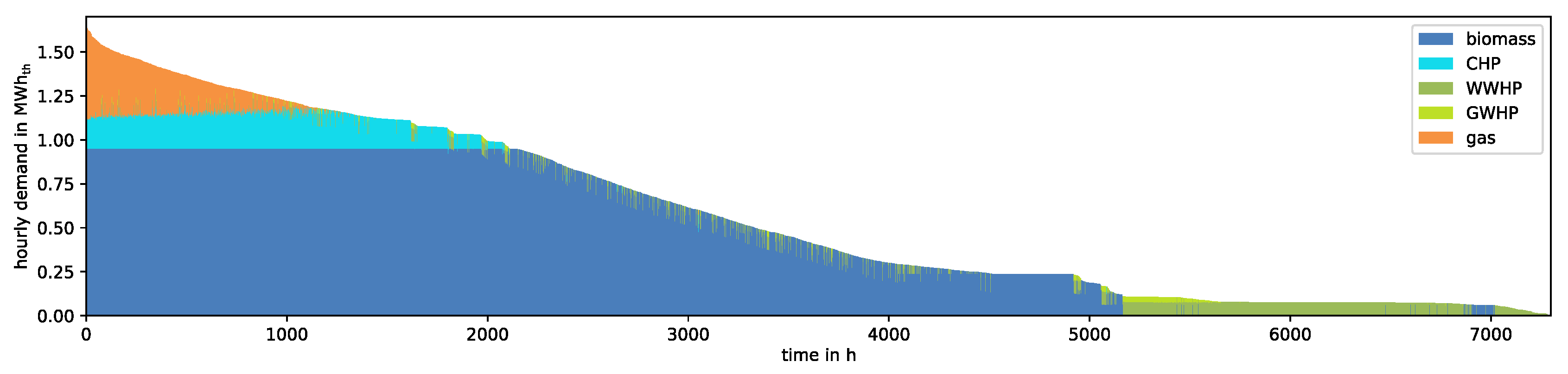
6.1.4. Results
As expected, the operational strategy is affected by the seasonal variations (temperature, solar irradiance), effectively resulting in seasonal operational modes that prefer different sources at different times of the year. These significant differences necessitate the evaluation of the system performance on a yearly basis, in order to provide a good basis for the choice of the optimal design.
Figure 7 summarizes the performance of the three considered system configurations in terms of yearly total energy production for the heat pumps (
), the biomass boiler (
) and the CHP (
). In all three cases, the thermal energy production of the gas boilers is around 230 MWh
/a. The figure shows that Configuration C—which has the largest WWHP—fails to exploit the full potential of the PV generation, resulting in the smallest total energy production of all configurations. This is due to the fact that the heat pump must not be operated below 80% of its maximum capacity, which in turn leads to a high threshold for turning it on in Configuration C. Configuration A—with the smallest WWHP—slightly falls behind Configuration B, which provides in this regard the best compromise as it exhibits the largest total generation from the heat pumps. Furthermore, in Configuration C, the WWHP’s high operational threshold causes not only an increase of biomass-based generation, but actually leads to an overcompensation at the cost of the CHP-based thermal generation compared to the other configurations.
Analysis of the detailed results from the co-simulation shows that Configuration B has the most favorable impact on the electrical system in view of integrating the on-site PV production. For instance, it shows the most significant improvement of the voltage band usage compared to non-hybrid system layouts by reducing the time and amount the maximum voltage band exceeds the 10% threshold.
In conclusion, even though the improvements from the system level point of view are limited due to the actual available PV generation and other practical constraints (e.g., economical aspects of increasing the CHP capacity), Configuration B shows overall the best thermal and electrical system performance. It optimally exploits the on-site PV generation via the heat pumps (
) while at the same time providing a modest reduction of fuel-based generation from the CHP and the biomass boiler (
). Furthermore, the design goal of minimizing on-site CO
is successfully met through the preference for the heat pumps, the biomass boiler and the CHP over the gas boiler (see
Figure 8).
6.2. HPS Example Application: Rural Residential Area
6.2.1. Technical System Layout
The system comprises a rural low-voltage electric grid with a total cable length of about 6.5 km. This network connects residential, commercial and agricultural customers, summing up to a total number of around 110 customers with a total annual power demand of around 775 MWh and PV systems that are feeding a total of 384 MWh per year.
The district heating network structure is typical for rural areas with low heat demand density (linear density of about 520 kWh/a/m and peak load demand of about 2.0 MW). An outdoor-temperature dependent heating curve is used to set the supply temperature between 90 (winter) and 70 C (summer). Return and supply pipes connect around 60% of the buildings in the area with a base heat generation plant responsible to keep the differential pressures at the consumer substations above a minimum.
Additionally, three electric boilers, i.e., electric heaters combined with thermal storage tanks, are installed as
coupling points between the networks. Adequate locations for the boilers were identified using a simulation-based sensitivity analysis in an early planning phase. These locations are especially prone to over voltage problems resulting from PV generation, an issue that might be eased by the active conversion of excess power generation. The volume of the thermal storage tanks and the capacities of the electric heaters are chosen as
degrees of freedom of this system. The system layout is illustrated in
Figure 9.
6.2.2. Operational Strategy
Decentralized electricity generation from PV systems of local prosumers pose challenges to the electrical distribution grid. Especially in times when PV production is high and electrical consumption is low, the upper voltage limit in the network can be exceeded and lines or transformers can be overloaded. To mitigate some of these problems, the operational strategy foresees to utilize excess power from PV overproduction. The local power grid is regarded as virtual power plant (VPP) and a supervisory controller tries to use as much of the excess power, i.e., negative residual load, locally via the installed electric heaters. Based on these ideas, a suitable operational strategy was implemented in Python using the following rule-based scheme (compare with
Section 4.4.1):
In case the VPP generates excess power, the electric heaters are set to utilize this power and store it in the respective storage tanks as long as their temperatures are below 95 C.
The thermal storage tanks are discharged as long as the temperatures in their top layers are above the current district heating supply temperature and only if there is enough district heating demand.
6.2.3. Design Optimization Strategy
The high number of possible system configurations and the use of a rule-based operational strategy makes HPS the most appropriate
optimization approach for this application.
Figure 10 illustrates the overall simulation-based optimization procedure.
The design optimization of the coupling units, i.e., finding optimal sizes for the defined degrees of freedom, rests upon the following optimization targets:
Reducing heat generation from the main supply unit in the district heating network is rewarded.
Costs for storage tanks and electric heater capacities linearly increase depending on size.
Potentially increased power imports into the electric network introduced by the electric heaters are penalized.
These targets are combined into a single objective function using appropriate weighting factors. The six-dimensional solution space is reduced by introducing bound constraints for the degrees of freedom, avoiding extremely high and low tank volumes and electric heater capacities.
The implementation relies on the use of a dedicated open-source tool for simulation-based optimization [
46], which allows parallelization on multiple machines and the use of optimization algorithms specialized for efficient black-box optimization. In this case, the freely available PSwarm solver [
45] is used that combines particle swarm optimization and pattern search for efficient global optimization. The pattern search relies on a coordinate search method that is responsible for local convergence, whereas the population-based particle swarm algorithm performs a global search enabling the exploration of the whole design space. The stopping criterion is based on a maximum number of co-simulation runs, i.e., objective function calls.
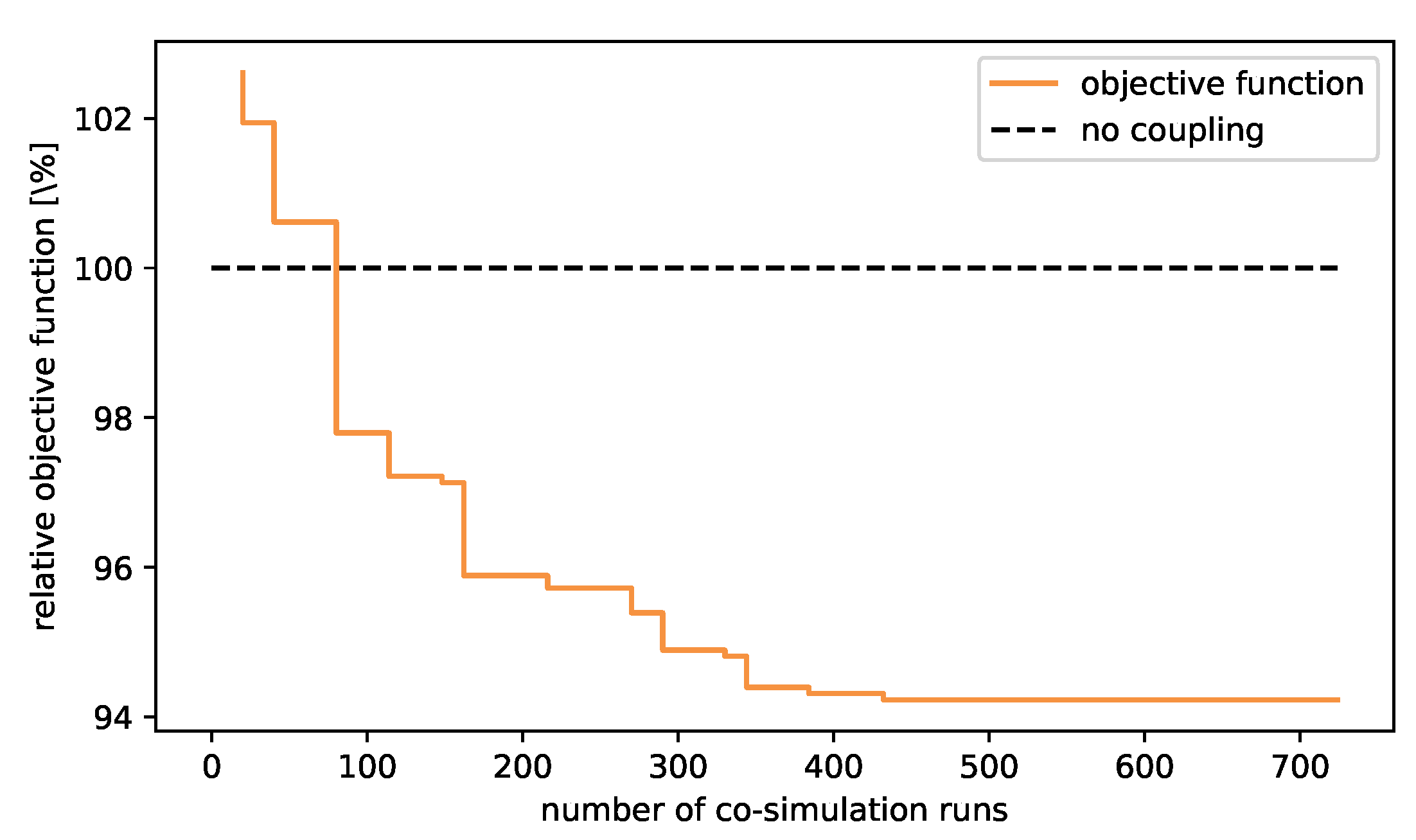
6.2.4. Results
The convergence of the objective function value over the number of co-simulation runs, i.e., assessed system configurations, is shown in
Figure 11. The objective function values are shown relative to a reference solution reflecting the current status quo, i.e., without any active coupling between the networks using the electric heaters. The optimization algorithm is able to outperform the reference scenario within only a few simulation runs. After around 450 runs, the algorithm converges to a minimum and stops after it exceeds the maximum number of objective function calls. Although this might only be a local minimum, the found minimum objective function is around 5.7% lower compared to the uncoupled case. The corresponding optimal system configuration exhibits electric heaters with a total capacity of 260 kW
and thermal storage tanks with a total volume of 20 m
.
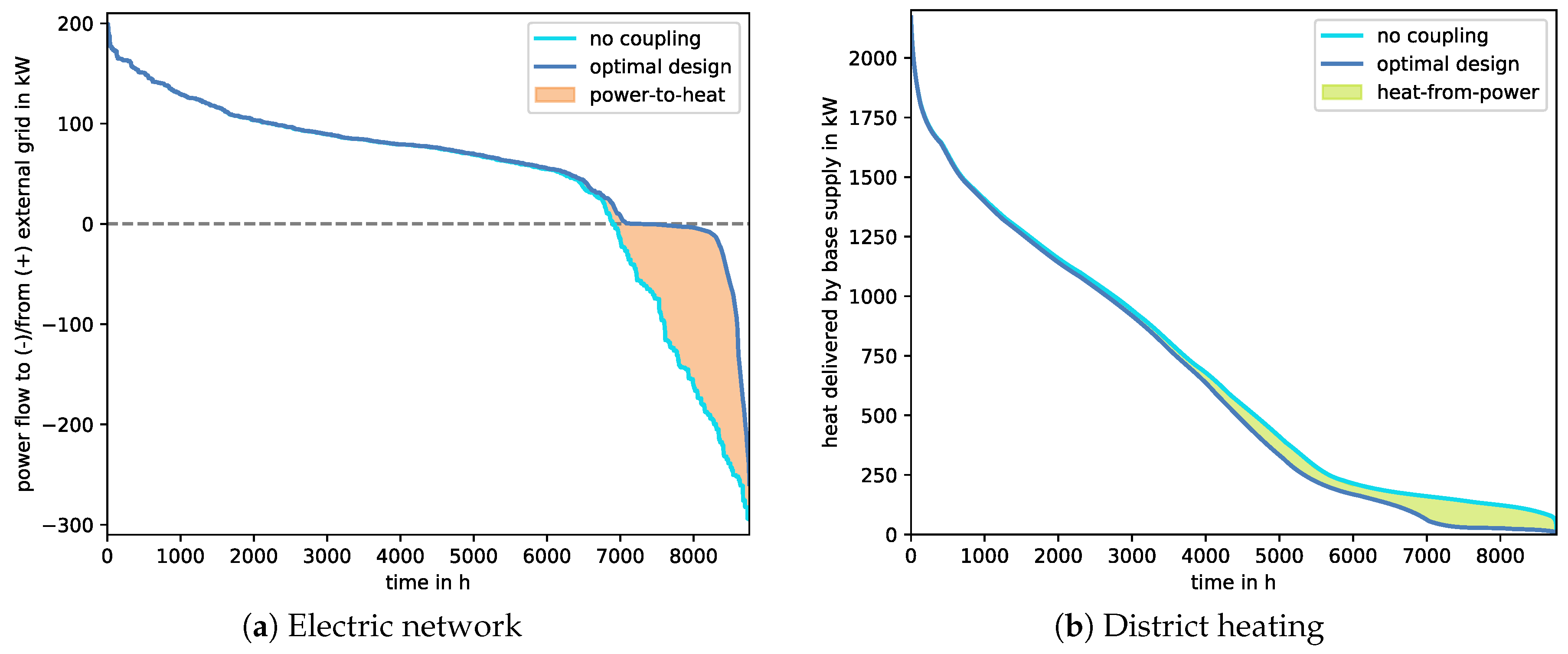
The impact on the two networks for the uncoupled case and the optimal design case in terms of load duration curves is shown in
Figure 12. A total of around 220 MWh electricity is converted in the optimal design case using electric boilers, illustrated by the colored areas. It can be seen that electric heaters in combination with thermal storage tanks are able to use a significant share of the excess power generation from PV by converting it into heat that is fed to the district heating network. Due to the seasonality of PV generation, district heating is mainly affected in low heat demand times, i.e., summer.
7. Conclusions
This work presents a simulation-based design approach for hybrid thermal-electrical distribution grids. The approach addresses the technical challenges of both domains while at the same time emphasizing their mutual control and operation, in order to exploit hitherto unused synergies in production, storage and consumption. As such, this approach is a significant extension of established tools for the design optimization of multi-energy systems.
Co-simulation is recommended for the technical assessment as a means to bridge the gap between single-domain simulation tools and the multi-domain target of investigation, providing a viable and practical approach to involve experts from different domains. A novel methodology is presented that links complementary design approaches to suitable operational strategies and optimization methods according to the state of the art. This enables the exploitation of synergies in the control and operation of hybrid thermal-electrical distribution systems in an optimal way. Furthermore, an implementation of the proposed approach based on state-of-the-art tools is presented. Finally, the applicability of the presented approach is demonstrated in two real-world applications.
Future work could apply this approach to other network-related multi-energy applications, such as design of short-term and long-term storage, peak shaving and others. A method for representative days selection for coupled heat and power networks could avoid the need for full-year simulations and, thus, reduce computational time. The use of computationally efficient model-based optimal control models or faster models for the physical system could enable the combination with meta-heuristic design optimization in a tolerable run time.
Author Contributions
Conceptualization, E.W. and B.L.; methodology, E.W. and B.L.; software, E.W., B.L., D.B., S.H. and T.F.; investigation, E.W., B.L., D.B., S.H. and T.F.; writing—original draft preparation, E.W. and B.L.; writing—review and editing, D.B., S.H. and R.H.; visualization, E.W. and B.L.; supervision, R.H. and E.W.; project administration, E.W. and B.L.; and funding acquisition, E.W. All authors have read and agreed to the published version of the manuscript.
Funding
Parts of this work were funded by the Austrian research funding association (FFG) within the scope of the research project OptHySys—Optimierung Hybrider Energienetze und -Systeme (project #848778). Parts of this work were carried out within the research project SmILES—Smart Integration of Energy Storages in Local Multi Energy Systems for maximising the Share of Renewables in Europe’s Energy Mix and received funding from the European Commission’s Horizon 2020 Research and Innovation Programme under the Grant Agreement No. 730936.
Acknowledgments
The authors want to acknowledge support provided by the cooperation college Smart Industrial Concept (SIC!).
Conflicts of Interest
The authors declare no conflict of interest. The funders had no role in the design of the study; in the collection, analyses, or interpretation of data; in the writing of the manuscript, or in the decision to publish the results.
Abbreviations
The following abbreviations are used in this manuscript:
| API | application programming interface |
| BB | biomass boiler |
| CHP | combined heat and power |
| DH | district heating |
| FMI | Functional Mock-up Interface |
| FMU | Functional Mock-up Unit |
| GB | gas boiler |
| GWHP | ground water heat pump |
| MPC | model predictive control |
| PV | photovoltaic |
| RES | renewable energy sources |
| VPP | virtual power plant |
| WWHP | waste water heat pump |
References
- Mancarella, P.; Andersson, G.; Pecas-Lopes, J.A.; Bell, K.R.W. Modelling of integrated multi-energy systems: Drivers, requirements, and opportunities. In Proceedings of the Power Systems Computation Conference (PSCC), Genoa, Italy, 20–24 June 2016; pp. 1–22. [Google Scholar]
- Van Beuzekom, I.; Gibescu, M.; Slootweg, J.G. A review of multi-energy system planning and optimization tools for sustainable urban development. In Proceedings of the IEEE Eindhoven PowerTech, Eindhoven, The Netherlands, 29 June–2 July 2015; pp. 1–7. [Google Scholar]
- Sustainable Energy Planning Research Group at Aalborg University in cooperation with PlanEnergi and EMD A/S. EnergyPLAN. Available online: https://www.energyplan.eu (accessed on 29 February 2020).
- HOMER Energy LLC. HOMER. Available online: https://www.homerenergy.com (accessed on 29 February 2020).
- Palensky, P.; Widl, E.; Elsheik, A. Simulating Cyber-Physical Energy Systems: Challenges, Tools and Methods. Syst. Man Cybern. Syst. IEEE Trans. 2014, 44, 318–326. [Google Scholar] [CrossRef]
- Fritzson, P. Introduction to Modeling and Simulation of Technical and Physical Systems with Modelica, 1st ed.; Wiley-IEEE Press: Hoboken, NJ, USA, 2011. [Google Scholar]
- Franke, R.; Wiesmann, H. Flexible modeling of electrical power systems—The Modelica PowerSystems library. In Proceedings of the of the 10th International Modelica Conference, Lund, Sweden, 10–12 March 2014; pp. 515–522. [Google Scholar]
- Vanfretti, L.; Rabuzin, T.; Baudette, M.; Murad, M. iTesla Power Systems Library (iPSL): A Modelica library for phasor time-domain simulations. SoftwareX 2016, 5, 84–88. [Google Scholar] [CrossRef]
- Wetter, M.; Zuo, W.; Nouidiu, T.S.; Pang, X. Modelica Buildings library. J. Build. Perform. Simul. 2014, 7, 253–270. [Google Scholar] [CrossRef]
- Bonvini, M.; Wetter, M. Gradient-based optimal control of batteries and HVAC in district energy systems. In Proceedings of the 14th Conference of International Building Performance Simulation Association (BS2015), Hyderabad, India, 7–9 December 2015; pp. 363–370. [Google Scholar]
- The Mathworks. MATLAB and Simulink. Available online: https://www.mathworks.com (accessed on 29 February 2020).
- Leitner, B.; Widl, E.; Gawlik, W.; Hofmann, R. A method for technical assessment of power-to-heat use cases to couple local district heating and electrical distribution grids. Energy 2019, 182, 729–738. [Google Scholar] [CrossRef]
- Wetter, M. Co-simulation of building energy and control systems with the Building Controls Virtual Test Bed. J. Build. Perform. Simul. 2011, 4, 185–203. [Google Scholar] [CrossRef]
- Widl, E.; Delinchant, B.; Kübler, S.; Li, D.; Müller, W.; Norrefeldt, V.; Nouidui, T.S.; Stratbücker, S.; Wetter, M.; Wurtz, F.; et al. Novel simulation concepts for buildings and community energy systems based on the Functional Mock-up Interface specification. In Proceedings of the Workshop on Modeling and Simulation of Cyber-Physical Energy Systems (MSCPES), Berlin, Germany, 14 April 2014; pp. 1–6. [Google Scholar]
- Georg, H.; Wietfeld, C.; Müller, S.C.; Rehtanz, C. A HLA Based Simulator Architecture for Co-simulating ICT Based Power System Control and Protection Systems. In Proceedings of the 3rd IEEE International Conference on Smart Grid Communications (SmartGridComm), Tainan, Taiwan, 5–8 November 2012. [Google Scholar]
- Rohjans, S.; Lenhoff, S.; Schütte, S.; Scherfke, S.; Hussain, S. Mosaik—A modular platform for the evaluation of agent-based Smart Grid control. In Proceedings of the IEEE PES ISGT Europe, Lyngby, Denmark, 6–9 October 2013; pp. 1–5. [Google Scholar]
- Galtier, V.; Vialle, S.; Dad, S.; Tavella, J.-P.; Lam-Yee-Mui, J.-P.; Plessis, G. FMI-Based Distributed Multi-Simulation with DACCOSIM. In Proceedings of the Symposium on Theory of Modeling and Simulation (TMS’15), Alexandria, VI, USA, 12–15 April 2015; pp. 804–811. [Google Scholar]
- Widl, E.; Müller, W.; Basciotti, D.; Henein, S.; Hauer, S.; Eder, K. Simulation of multi-domain energy systems based on the Functional Mock-up Interface specification. In Proceedings of the International Symposium on Smart Electric Distribution Systems and Technologies (EDST), Vienna, Austria, 8–11 September 2015; pp. 510–515. [Google Scholar]
- Widl, E.; Jacobs, T.; Schwabender, D.; Nicolas, S.; Basciotti, D.; Henein, S.; Noh, T.-G.; Terreros, O.; Schuelke, A.; Auer, H. Studying the potential of multi-carrier energy distribution grids: A holistic approach. Energy 2018, 153, 519–529. [Google Scholar] [CrossRef]
- Geidl, M.; Andersson, G. Optimal Power Flow of Multiple Energy Carriers. IEEE Trans. Power Syst. 2007, 22, 145–155. [Google Scholar] [CrossRef]
- Walker, S.; Labeodan, T.; Maassen, W.; Zeiler, W. A review study of the current research on energy hub for energy positive neighborhoods. In Proceedings of the CISBAT 2017 International Conference, Lausanne, Switzerland, 6–8 September 2017. [Google Scholar] [CrossRef]
- Wetter, M.; Wright, J. A comparison of deterministic and probabilistic optimization algorithms for nonsmooth simulation-based optimization. Build. Environ. 2004, 39, 989–999. [Google Scholar] [CrossRef]
- Huang, Y.; lei Niu, J. Optimal building envelope design based on simulated performance: History, current status and new potentials. Energy Build. 2016, 117, 387–398. [Google Scholar] [CrossRef]
- Niemelä, T.; Kosonen, R.; Jokisalo, J. Cost-optimal energy performance renovation measures of educational buildings in cold climate. Appl. Energy 2016, 183, 1005–1020. [Google Scholar] [CrossRef]
- Delgarm, N.; Sajadi, B.; Kowsary, F.; Delgarm, S. Multi-objective optimization of the building energy performance: A simulation-based approach by means of particle swarm optimization (PSO). Appl. Energy 2016, 170, 293–303. [Google Scholar] [CrossRef]
- Nguyen, A.T.; Reiter, S.; Rigo, P. A review on simulation-based optimization methods applied to building performance analysis. Appl. Energy 2014, 113, 1043–1058. [Google Scholar] [CrossRef]
- Wang, H.; Wang, H.; Zhou, H.; Zhu, T. Modeling and optimization for hydraulic performance design in multi-source district heating with fluctuating renewables. Energy Convers. Manag. 2018, 156, 113–129. [Google Scholar] [CrossRef]
- van der Heijde, B.; Vandermeulen, A.; Salenbien, R.; Helsen, L. Integrated Optimal Design and Control of Fourth Generation District Heating Networks with Thermal Energy Storage. Energies 2019, 12, 2766. [Google Scholar] [CrossRef]
- Widl, E.; FUMOLA–Functional Mock-up Laboratory. Sourceforge.net. Available online: http://sourceforge.fumola.net (accessed on 29 February 2020).
- Blochwitz, T.; Otter, M.; Arnold, M.; Bausch, C.; Elmqvist, H.; Junghanns, A.; Maus, J.; Monteiro, M.; Neidhold, T.; Neumerkel, D.; et al. The Functional Mockup Interface for Tool independent Exchange of Simulation Models. In Proceedings of the 8th International Modelica Conference, Dresden, Germany, 20–22 March 2011. [Google Scholar]
- Dassault Systèmes. DYMOLA Systems Engineering. Available online: https://www.3ds.com/products-services/catia/products/dymola (accessed on 29 February 2020).
- Leitner, B. Modelica DisHeatLib library. GitHub.com. Available online: https://github.com/AIT-IES/DisHeatLib (accessed on 29 February 2019).
- Modelica IBPSA Library. Available online: https://github.com/ibpsa/modelica-ibpsa (accessed on 21 March 2020).
- Kusuda, T.; Achenbach, R.P. Earth temperature and thermal diffusivity at selected stations in the United States. ASHRAE Trans. 1965, 71, 61–75. [Google Scholar]
- Colebrook, C.F. Turbulent flow in pipes, with particular reference to the transition region between the smooth and rough pipe laws. J. Inst. Civ. Eng. 1939, 11, 133–156. [Google Scholar] [CrossRef]
- Van der Heijde, B.; Fuchs, M.; Ribas Tugores, C.; Schweiger, G.; Sartor, K.; Basciotti, D.; Müller, D.; Nytsch-Geusen, C.; Wetter, M.; Helsen, L. Dynamic equation-based thermo-hydraulic pipe model for district heating and cooling systems. Energy Convers. Manag. 2017, 151, 158–169. [Google Scholar] [CrossRef]
- Bergman, T.; Lavine, A.; Incropera, F.; DeWitt, D. Fundamentals of Heat and Mass Transfer, 8th ed.; John Wiley & Sons Inc.: Hoboken, NJ, USA, 2018. [Google Scholar]
- Kleinbach, E.; Beckman, W.; Klein, S. Performance study of one-dimensional models for stratified thermal storage tanks. Sol. Energy 1993, 50, 155–166. [Google Scholar] [CrossRef]
- DIgSILENT PowerFactory. Available online: http://www.digsilent.com (accessed on 29 February 2020).
- Widl, E.; Leitner, B. The FMI++ PowerFactory FMU Export Utility. Sourceforge.net. Available online: http://powerfactory-fmu.sourceforge.net (accessed on 29 February 2020).
- Widl, E. The FMI++ MATLAB Toolbox for Windows. Sourceforge.net. Available online: http://matlab-fmu.sourceforge.net (accessed on 29 February 2020).
- Widl, E. FMI++ Python Interface. Python Package Index. Available online: https://pypi.org/project/fmipp (accessed on 29 February 2020).
- Eberhart, R.C.; Kennedy, J. A new optimizer using particle swarm theory. In Proceedings of the Sixth International Symposium on Micromachine and Human Science, Nagoya, Japan, 4–6 October 1995; pp. 39–43. [Google Scholar]
- Storn, R.; Price, K. Differential Evolution: A Simple and Efficient Adaptive Scheme for Global Optimization over Continuous Spaces. Glob. Optim. 1997, 11, 341–359. [Google Scholar] [CrossRef]
- Vaz, A.; Vicente, L. PSwarm: A hybrid solver for linearly constrained global derivative-free optimization. Optim. Methods Softw. 2009, 24, 669–685. [Google Scholar] [CrossRef]
- Pesendorfer, B.; Widl, E. The optFUMOLA package: A simulation-based black-box optimization library and interface. In Proceedings of the Workshop on Modeling and Simulation of Cyber-Physical Energy Systems (MSCPES), Pittsburgh, PA, USA, 21 April 2017; pp. 1–6. [Google Scholar]
Figure 1.
Scope of the design approach proposed in this work.
Figure 1.
Scope of the design approach proposed in this work.
Figure 2.
Overview of local control (process level) versus operational strategy (system level).
Figure 2.
Overview of local control (process level) versus operational strategy (system level).
Figure 3.
Comparison of the Optimal Control Scan (OCS) and the Heuristic Parameter Scan (HPS), indicating higher (↑) and lower (↓) implementation effort for specific sub-tasks.
Figure 3.
Comparison of the Optimal Control Scan (OCS) and the Heuristic Parameter Scan (HPS), indicating higher (↑) and lower (↓) implementation effort for specific sub-tasks.
Figure 4.
Schematic view of the relation between co-simulation and optimizer for: (a) the Optimal Control Scan (OCS); and (b) the Heuristic Parameter Scan (HPS).
Figure 4.
Schematic view of the relation between co-simulation and optimizer for: (a) the Optimal Control Scan (OCS); and (b) the Heuristic Parameter Scan (HPS).
Figure 5.
Schematic overview of the hybrid system layout for the suburban industrial area (GB, gas boiler; BB, biomass boiler; GWHP, ground water heat pump; WWHP, waste water heat pump; PV, photovoltaic module; CHP, combined heat and power plant). The components targeted by the design optimization process are highlighted in orange.
Figure 6.
Schematic overview of the OCS workflow applied to the system design of the suburban industrial area.
Figure 6.
Schematic overview of the OCS workflow applied to the system design of the suburban industrial area.
Figure 7.
Comparison of the yearly thermal energy production of heat pumps, biomass boiler and CHP for the three considered system configurations (Configuration A, Configuration B and Configuration C).
Figure 7.
Comparison of the yearly thermal energy production of heat pumps, biomass boiler and CHP for the three considered system configurations (Configuration A, Configuration B and Configuration C).
Figure 8.
Yearly load duration curve.
Figure 8.
Yearly load duration curve.
Figure 9.
Schematic overview of the hybrid system layout for the rural residential area, depicting the electrical distribution network and the district heating network (EH, electric heater; TES, thermal energy storage). The components targeted by the design optimization process are highlighted in orange.
Figure 10.
Schematic overview of the HPS workflow applied to the system design of the rural residential area.
Figure 10.
Schematic overview of the HPS workflow applied to the system design of the rural residential area.
Figure 11.
Convergence of objective function shown relative to the reference scenario without coupling between the networks, i.e., no electric boilers.
Figure 11.
Convergence of objective function shown relative to the reference scenario without coupling between the networks, i.e., no electric boilers.
Figure 12.
Load duration curves for the electric network (a) and the district heating network (b) for the uncoupled and the optimal design system configurations.
Figure 12.
Load duration curves for the electric network (a) and the district heating network (b) for the uncoupled and the optimal design system configurations.
Table 1.
Key prerequisites and modeling requirements for the assessment of hybrid networks.
Table 1.
Key prerequisites and modeling requirements for the assessment of hybrid networks.
| Key Prerequisites |
|---|
| KP1 | A method for analyzing coupled thermal and electrical distribution systems on a network level is required, which allows a technical assessment with reasonably high spatial and temporal resolution. |
| KP2 | Given a system layout with certain degrees of freedom and a design criterion represented by a (scalar) objective function, a suitable method is needed to optimize this layout by minimizing this objective function. |
| KP3 | The tools and methods used for analysis and optimization must enable domain experts to actively participate in the design process. |
| Modeling Requirements |
| MR1 | When combined, the (sub-)models need to capture the dynamic interactions between the domains, i.e., electric, thermal and control, on the system level. This is the prerequisite for enabling the design of new coupling concepts and operational strategies for hybrid distribution systems. |
| MR2 | At the same time, they have to enable the detailed study of the impact on the individual domains, from the network down to the component level. This is required to check the feasibility of any coupling concept and/or operational strategy from the technical perspective of the respective domains. |
| MR3 | In addition, the proper representation of local controls at process level and overall operational strategies is required. Their proper interaction with the models of the physical processes is fundamental for a complete system representation and can come in various forms, e.g., from simple PID to model predictive control. |
Table 2.
Comparison of modeling and simulation approaches in view of key prerequisites and modeling requirements.
Table 2.
Comparison of modeling and simulation approaches in view of key prerequisites and modeling requirements.
| | KP1 | KP2 | KP3 | MR1 | MR2 | MR3 |
|---|
| established design optimization tools | − | + | ∘ | + | − | − |
| domain-specific tools | − | ∘ | + | − | − | − |
| multi-domain languages | + | ∘ | ∘ | + | + | − |
| proposed approach (based on co-simulation) | + | ∘ | + | + | + | + |
Table 3.
Considered system configurations.
Table 3.
Considered system configurations.
| Configuration Name | WWHP Size (kW) | GWHP Size (kW) |
|---|
| A | 100 | 50 |
| B | 150 | 50 |
| C | 200 | 50 |
© 2020 by the authors. Licensee MDPI, Basel, Switzerland. This article is an open access article distributed under the terms and conditions of the Creative Commons Attribution (CC BY) license (http://creativecommons.org/licenses/by/4.0/).

 ,
, 


