Article

Optimization of Perfluoropolyether-Based Gas Diffusion Media Preparation for PEM Fuel Cells

by
Riccardo Balzarotti
1,
Saverio Latorrata
2,*,
Marco Mariani
3,
Paola Gallo Stampino
2 and
Giovanni Dotelli
2
1
Department of Energy, Politecnico di Milano, Via Lambruschini 4, 20156 Milano, Italy
2
Department of Chemistry, Materials and Chemical Engineering “Giulio Natta”, Politecnico di Milano, Piazza Leonardo da Vinci 32, 20133 Milano, Italy
3
Department of Mechanical Engineering, Politecnico di Milano, Via La Masa 1, 20156 Milano, Italy
*
Author to whom correspondence should be addressed.
Energies 2020, 13(7), 1831; https://doi.org/10.3390/en13071831
Submission received: 12 March 2020 / Revised: 3 April 2020 / Accepted: 8 April 2020 / Published: 10 April 2020

Abstract

:
A hydrophobic perfluoropolyether (PFPE)-based polymer, namely Fluorolink® P56, was studied instead of the commonly used polytetrafluoroethylene (PTFE), in order to enhance gas diffusion media (GDM) water management behavior, on the basis of a previous work in which such polymers had already proved to be superior. In particular, an attempt to optimize the GDM production procedure and to improve the microporous layer (MPL) adhesion to the substrate was carried out. Materials properties have been correlated with production routes by means of both physical characterization and electrochemical tests. The latter were performed in a single PEM fuel cell, at different relative humidity (namely 80% on anode side and 60%/100% on cathode side) and temperature (60 °C and 80 °C) conditions. Additionally, electrochemical impedance spectroscopy measurements were performed in order to assess MPLs properties and to determine the influence of production procedure on cell electrochemical parameters. The durability of the best performing sample was also evaluated and compared to a previously developed benchmark. It was found that a final dipping step into PFPE-based dispersion, following MPL deposition, seems to improve the adhesion of the MPL to the macro-porous substrate and to reduce diffusive limitations during fuel cell operation.

1. Introduction

The continuous increase in world energy demand as well as in energy use per person is leading to new challenges in energy production. A sustainable approach to energy production and storage is likely to be followed, as the actual use of fossil fuels has become insufficient for meeting both energy demands and environmental requirements in terms of greenhouse gas emissions [1]. Hydrogen is the most valuable candidate to fulfill these requirements, as it allows for clean and efficient energy storage and production [2,3]. From the energy conversion point of view, fuel cells are very promising devices, as they are able to produce electricity and heat from multiple sources, without drawbacks from the point of view of emissions [4].
Among others, proton exchange membrane fuel cells (PEMFCs) are considered very promising due to their zero-emission energy production process. In addition to this, PEMFCs are characterized by a high efficiency, low operating temperature, compactness and fast response to load change [5,6,7].
Among the PEMFCs components, the gas diffusion medium (GDM) plays a crucial role, especially in terms of water management and reactants diffusion to electrodes. The GDM is composed of two parts: a gas diffusion layer (GDL), which introduces macro-porosity properties that optimize reactants distribution from the flow field channels to the catalyst layer, and a micro-porous layer (MPL) that reduces liquid flooding and contact resistances [8,9]. The latter component is usually obtained by blade coating a thin carbon-based layer on the GDL surface and its addition to cell assembly was reported to improve cell performance [10].
In view of the position of the GDM in the cell assembly and of its role in the device operation, some features can be identified: the GDM should be permeable to reactants and products and, at the same time, it should display good properties in terms of electrical and thermal conductivity [10,11,12]. Finally, good mechanical properties would be highly desirable, in order to prevent damages and a consequent performance drop. Concerning thermal and electrical conductivity, good performances are easily achieved by using carbon-based materials. On the contrary, permeability is a more trivial feature, as specific GDL properties are used, which sometimes compete with each other. Polymer content in GDLs is a typical example of this duality. In order to prevent mass transport limitations, GDLs should be permeable to reactants, allowing a proper supply of fuel and oxidants to the catalyst-coated membrane (CCM). In a similar way, cathode side flooding should be avoided by properly managing excess water removal. In order to achieve this, GDLs are usually made hydrophobic by adding stable fluorinated polymers [10]. In many cases, polytetrafluoroethylene (PTFE) is used in order to obtain the desired water-repellent behavior, with polymer-loading on the layer surface in a range between 5% and 30% by weight [13]; nonetheless, commercial components featuring up to 70% PTFE as both hydrophobic agent and binder have been employed in other valuable works [14,15]. Thus, the best performance as a function of polymer content is the result of two competing properties: if a small quantity of polymer is used, low values in terms of ohmic losses due to polymer dielectric properties will be present; nevertheless, at the same time, poor hydrophobic properties will be obtained.
GDLs are usually employed in the form of carbon paper or carbon cloths, with different properties in terms of reactants/products diffusion and pores size distribution [16,17,18]. The latter property is of particular interest to enhance device performance: an optimum in pores dimension should be found, as higher pores enhance species gas diffusion, but they increase ohmic losses [11]. In this view, the MPL is coated onto the GDL aiming to maximize the contact between the catalyst layer and the GDL. Additionally, transport properties, and thus electrochemical performance, are enhanced thanks to the introduction of a micro-porosity in the diffusion media [17]. In many works, the presence of the MPL in cell assembly was proven to be of remarkable importance for improving the overall device performance [8,10,17,19,20,21,22]; the hydrophobicity of the MPL material together with its micro-porosity was found to enhance the device performance, due to better properties in terms of water removal in the Membrane Electrode Assembly (MEA) [23,24,25,26].
The MPL is typically produced by mixing a carbon powder with a hydrophobic agent, solvents and surfactants in order to produce a carbon ink. Then, the carbon-based ink is deposited onto the GDL surface by using a slurry coating deposition technique (i.e., blade coating, tape casting or spray coating) and, finally, the GDM is heat treated to remove liquid components and to consolidate the MPL layer [10]. MPL adhesion on GDL is a crucial requirement to be fulfilled in order to reach the target of device durability. MPL detachment is a highly undesired phenomenon, which leads to a decrease in device performance due to catalyst deactivation and mass transfer limitations [9].
In this work, an anionic polyurethane polymer based on a perfluoropolyether (PFPE) backbone, which had been already proved to be a viable alternative to the commonly used PTFE [27], was employed as hydrophobic agent in GDMs production. Different manufacturing routes were investigated, aiming to maximize water management and adhesion properties. The achievement of these targets was coupled with the enhancement of the electrochemical performance of the device. Samples were characterized both from the physical and electrochemical point of view, in order to assess the feasibility of production processes.

2. Materials and Methods
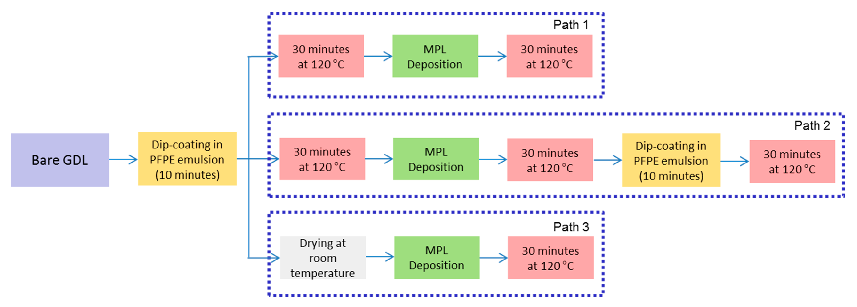
2.1. Preparation

In order to obtain a water-repellent gas diffusion medium, both GDL and MPL have to be made hydrophobic. In the present work, such a goal was accomplished by using fluorinated polymers and by applying different procedures. In the case of GDLs, a macro-porous carbon cloth (SCCG 5N by SAATI Group, Appiano Gentile, Italy) was treated by means of a dipping/drying procedure in a fluorinated aqueous emulsion.
The MPL was produced by blade coating deposition of an ink precursor onto the GDL surface, according to a procedure reported in literature [28]. In a typical experiment, carbon black (Vulcan XC-72R, Cabot Italiana S.p.A., Ravenna, Italy) was dispersed into a solution containing distilled water and isopropyl alcohol (Sigma-Aldrich). After the addition of Fluorolink® P56 (Solvay Solexis, Milan, Italy), a perfluoropolyether (PFPE)-based polymer, as hydrophobic agent, the four components were mixed for 10 min at 8000 rpm, by using an UltraTurrax T25 homogenizer (IKA Instruments, Staufen, Germany). The employed concentration of the polymer with respect to the carbon black was 6 wt. %, which allowed the achievement of the highest performance in the reference [27].
Before applying MPLs coating, GDL substrates were pre-treated by dipping in a PFPE emulsion (1 wt. %), and different drying processes, depending on the specific preparation route, were carried out. Inks were deposited onto such pre-treated GDLs by using the blade coating technique. A K-Control Coater device (RK Print-Coat Instruments Ltd., Litlington, UK) was used; the gap between blade and substrate, corresponding to the wet thickness of the MPL, and the blade speed were set at 40 μm and 0.154 m s−1, respectively. Different production paths were applied in order to optimize the MPL adhesion to the GDL substrate. A graphical representation of them is reported in Figure 1, while Table 1 shows the polymer amount employed for both GDLs and MPLs preparation; for the sake of comparison data about the reference sample [27] is also reported.
In Path 1, a common approach was used: in the first step, the GDL was made hydrophobic by dip coating in a 1 wt. % PFPE emulsion, then it was heat treated at 120 °C for 10 min. Such a temperature, that is much lower than the one employed in the heat treatment of common PTFE-containing samples (around 350 °C) [10], was selected on the basis of the authors’ previous works [27,28], and was intended to eliminate solvent and surfactant only; indeed, it was found that treating amorphous PFPE-based polymers at a higher temperature would be meaningless [28]. Then, the MPL was deposited and the same thermal treatment at 120 °C was performed. In Path 2, following the same operation as for Path 1, a final dipping into the polymer emulsion followed by heat treatment was added, in order to enhance the MPL adhesion to the substrate. Path 3 represents a new approach to GDMs production as an attempt to maximize MPL-GDL interactions was made by performing a single heat treatment; indeed, the polymer-treated GDL was only dried at room temperature and directly coated by the MPL; then, the obtained GDM was heat treated at 120 °C for 30 min.

2.2. Characterization

The surface hydrophobicity of GDMs was assessed by means of static contact angle measurements. For this purpose, an OCA 20 instrument (DataPhysics Instrument GmbH, Filderstadt, Germany) was used. Further details regarding contact angle measurements on PEMFCs components have been reported by the authors elsewhere [28].
The pores size distribution of the prepared samples was assessed through mercury intrusion porosimetry (MIP) by means of an Autopore V9600 by Micrometrics Instrument Corporation.
The produced samples were assembled in a single lab-scale fuel cell; in order to focus on GDMs properties only, a commercial catalyst coated membrane (CCM, provided by Baltic Fuel Cells GmbH, Germany) was employed for the electrochemical tests. Nafion 212 was the electrolytic membrane while platinum was the catalytic active phase, with different loadings at the anode side (0.2 mg cm−2) and at the cathode side (0.4 mg cm−2) due to different kinetics of oxidation and reduction reactions. The electrodes’ active area was equal to 23 cm2. Finally, graphitic bipolar plates were used for reagents distribution; a single feeding channel was used for supplying hydrogen, while a triple serpentine was used for air. Various operating conditions were tested, both in terms of temperature and humidity. Electrochemical experiments were carried out at 60 °C and 80 °C, with different inlet gas humidification levels in order to evaluate the water management properties of cell components. The relative humidity (RH) of the hydrogen fed to the anode was kept constant at 80%, while it was set at 60% and 100% for the cathodic air. Inlet volumetric flow rates were fixed at 0.25 Nl min−1 for hydrogen and 1 Nl min−1 for air; these values correspond to stoichiometric ratios of 1.3 and 2.2 for hydrogen and air, respectively, calculated at 1.2 A cm−2.
Polarization curves were obtained by monitoring the fuel cell current, voltage and power during operation by using an electronic load (RBL488 50-150-800, TDI Power, Hackettstown, New Jersey, USA), in galvanostatic mode, from open circuit voltage (OCV) to high current density values with 0.09 A cm−2 steps. Electrochemical Impedance Spectroscopy (EIS) was used together with polarization curves in order to investigate the materials’ electrochemical properties and behavior during cell operation. By means of a proper equivalent circuit model [29], EIS allows us to quantify the different contributions to cell potential losses; each of them is characteristic of physical-chemical processes which take place in the fuel cell, and they can be investigated to compare materials’ properties. EIS was performed by means of a frequency response analyzer (FRA, Solartron 1260, Solartron Analytical, Farnborough, England, UK), which was connected to the electronic load. A typical experiment was performed in galvanostatic mode, in the frequency range 0.5 Hz-1 kHz [30]. The obtained spectra were fitted using the ZView software (Scribner Associates, Southern Pines, North Carolina, USA). Fuel cell internal losses were modeled using an equivalent electrical circuit which consisted of a resistance representing ohmic losses in series with two capacitance/resistance parallel circuits. The first parallel circuit was introduced in order to model charge transfer resistance by quantifying activation polarization, while the second one modelled mass transfer resistance by determining concentration polarization [31,32]. Due to the porous nature of the analyzed components, constant phase elements (CPE) were used as circuit elements instead of pure capacitances [33,34].
The durability of the best performing sample and of the PFPE-based benchmark [27] was evaluated. This was realized by operating the fuel cell at a constant current density (0.5 A cm−2) for 1000 h at 60 °C and RH 80–100%, performing polarization tests every 168 h (i.e., one week).
The same samples were also subjected to an ex-situ mechanical accelerated stress test (AST) in order to have a faster and more real evaluation of the durability without carrying out tests for thousands of hours. As a matter of fact, mechanical degradation was proven to be the most critical stressor for GDMs, mainly due to detachment of the MPL surface carbon, which may be caused by both reactants flow and water [35]. The GDMs were assembled in a dummy cell with a 210 µm thick Teflon membrane as a separator without catalyst layers for preventing chemical stresses on the samples [12]. For the same reason, only air was supplied continuously to each side of the cell for 1000 h. Flow rates were 0.5 NL min−1 at the dummy anode and 2 NL min−1 at the dummy cathode, so twofold values compared to the ones used for standard electrochemical tests aiming to quicken mechanical degradation. Electrochemical tests in the running fuel cell were performed again upon the AST experiments, in order to evaluate the effects of the imposed stressors on the GDMs.

3. Results

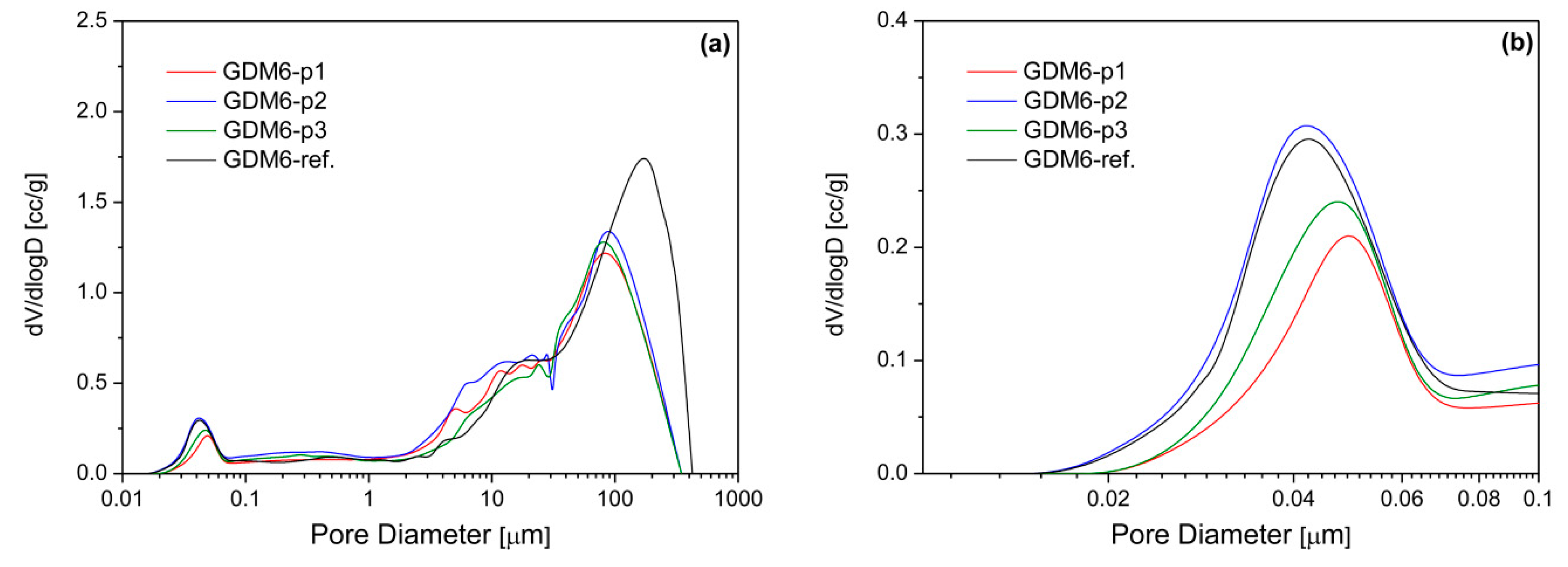
3.1. Physical Characterization

Due to the strong influence of GDMs’ water management properties on fuel cell performance, the components’ hydrophobicity was evaluated using static contact angle analysis; the results of such measurements are reported in Table 2. Values were recorded both before cell testing (BCT) and after cell testing (ACT); in the latter case, measurements were performed at both the anode side and the cathode side. Ten measurements per sample were performed and then averaged.
All the samples were close to the superhydrophobicity limit (150°) upon preparation. While GDMs prepared by paths 2 and 3 show practically unchanged contact angle values upon electrochemical tests, both for anodic and cathodic samples, the GDM prepared by means of path 1 exhibited a dramatic decrease in hydrophobicity of the anodic sample. This behavior can be ascribed to the water back-diffusion taking place at a high current density due to unbalanced pressure and concentration between electrodic compartments; this sample was not able to withstand the unavoidable back-diffusion because of the possible low adhesion between MPL and GDL. Indeed, due to that faulty adhesion, part of the MPL surface carbon might have been lost and the measurement of the contact angle affected by the back layer which was treated with a lower quantity of PFPE. As a rough confirmation of this, the loss of material of the GDMs upon the electrochemical testing procedure was measured and reported in Table 2 as well. Such loss is mainly due to the detachment of the MPLs surface carbon. Of course, the cell disassembling procedure can increase the material loss, but this is true and always the same phenomenon for all the samples. GDM6-p2 and GDM6-ref. showed a probable better adhesion of the MPL to the GDL, since a loss that is much lower than the one of the other samples was observed.
The results of the porosimetry tests in terms of pores size distribution (Figure 2) show important differences between the samples. The porosity of the GDM is crucial because it influences the efficiency of gases and water transport across such components. The classification of GDMs pores does not correspond to the one adopted in other fields and is as follows: macropores (pores radius > 5 µm), mesopores (0.07 µm < radius < 5 µm), and micropores (radius < 0.07 µm) [17]. Accordingly, in Figure 2, it is possible to notice the presence of micropores which are more pronounced for GDM6-p2 than for the other new samples. Such behavior can result in a better water management, since a greater amount of micropores would enhance the capillary effect of the MPL, which could remove the excess water more quickly [17,36]; moreover, the average pore diameter of GDM6-p2 (around 40 nm) is lower than the one shown by the other new samples (in the range 47–50 nm), and very similar to that exhibited by GDM6-ref. Such a result will prove crucial for the electrochemical performance, especially in the high current density region, where a high amount of water is produced. Conversely, it must be also noticed that the macropores region is very similar for all the new samples, due to the presence of the same PFPE-based GDL substrate—independent of the process of dipping or thermal treatment followed. The difference with the reference sample in which the GDL had been treated with PTFE is clear, but the higher impact of macropores is on gas transport from the bipolar plates to the catalyst layer [12].

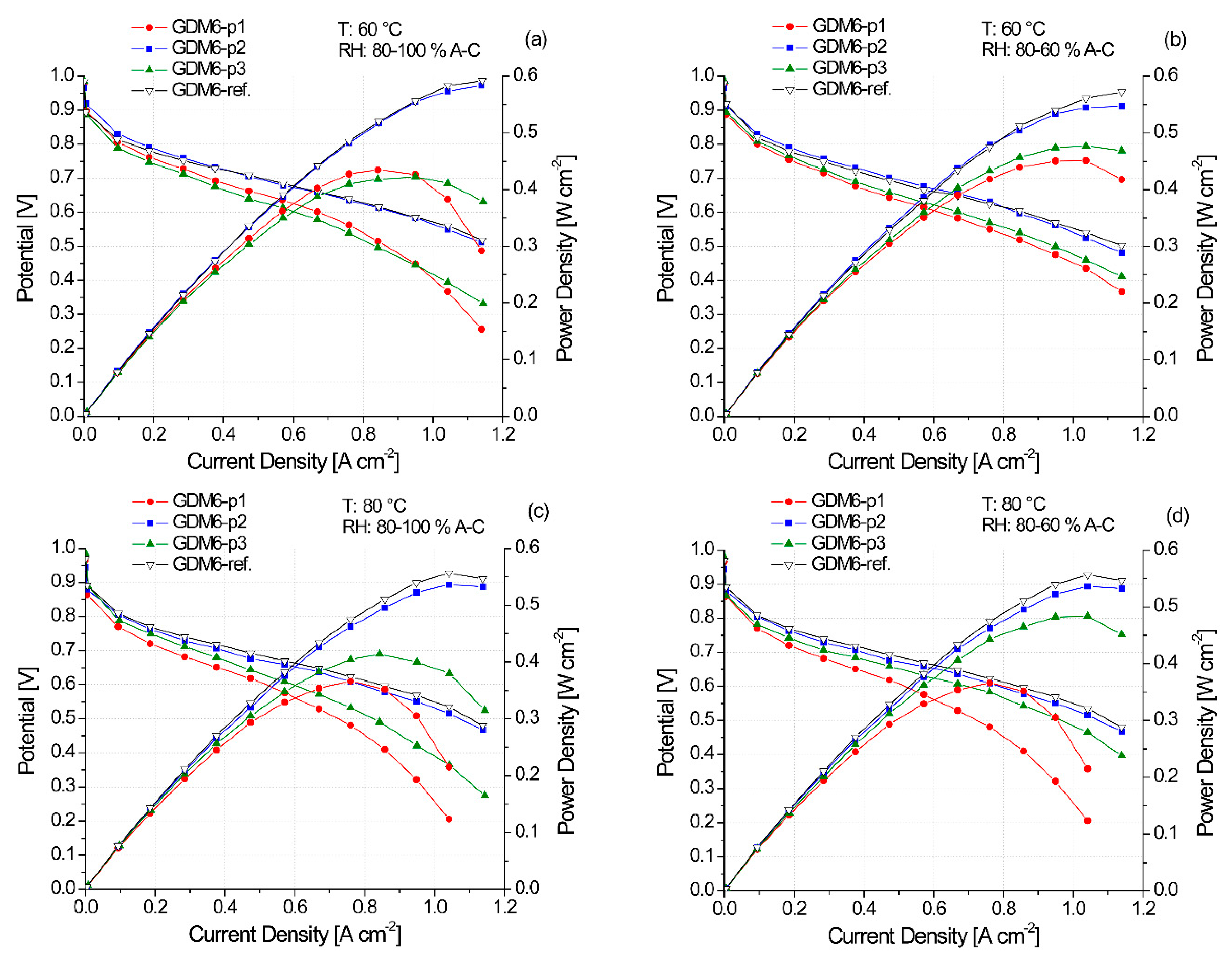
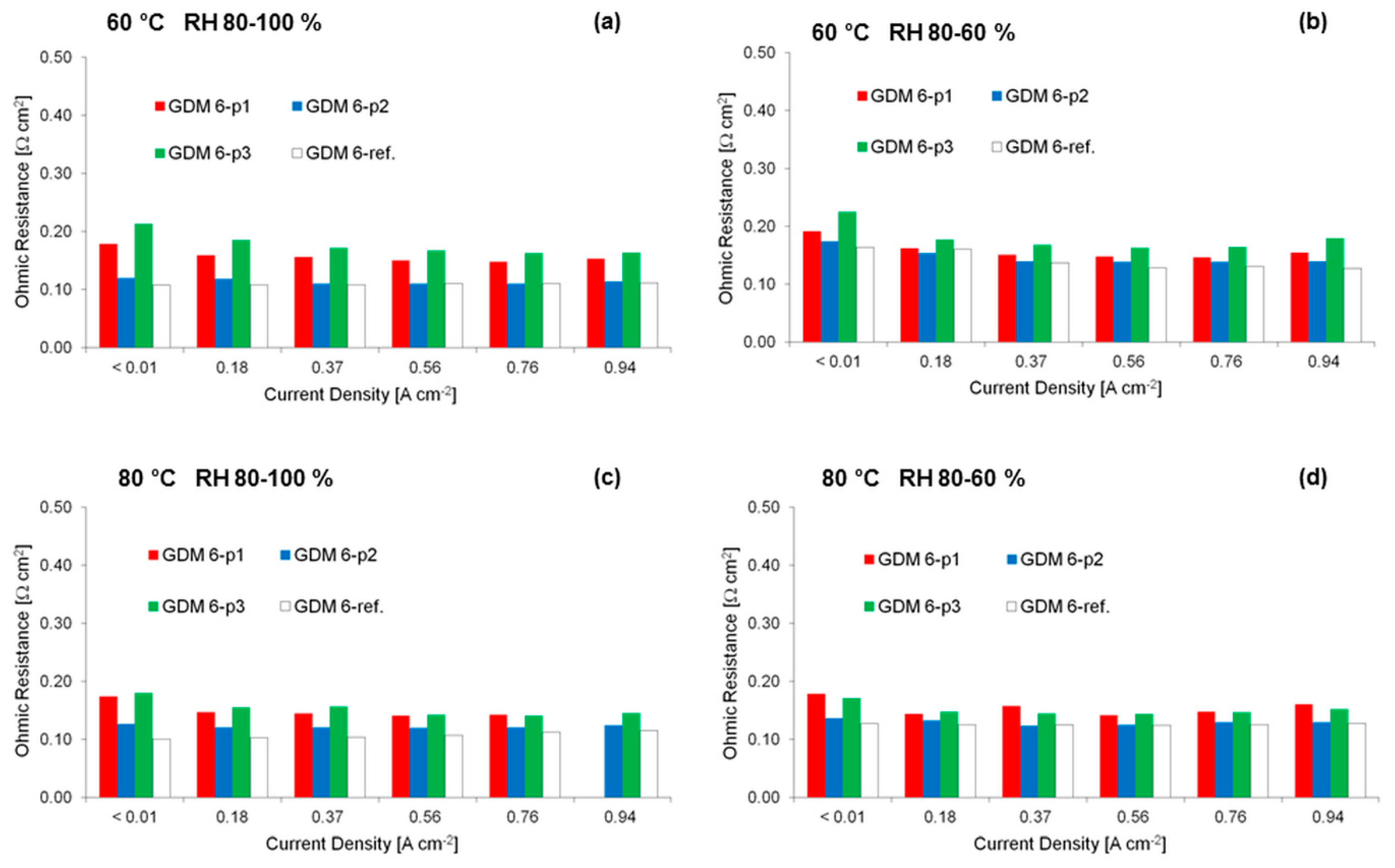
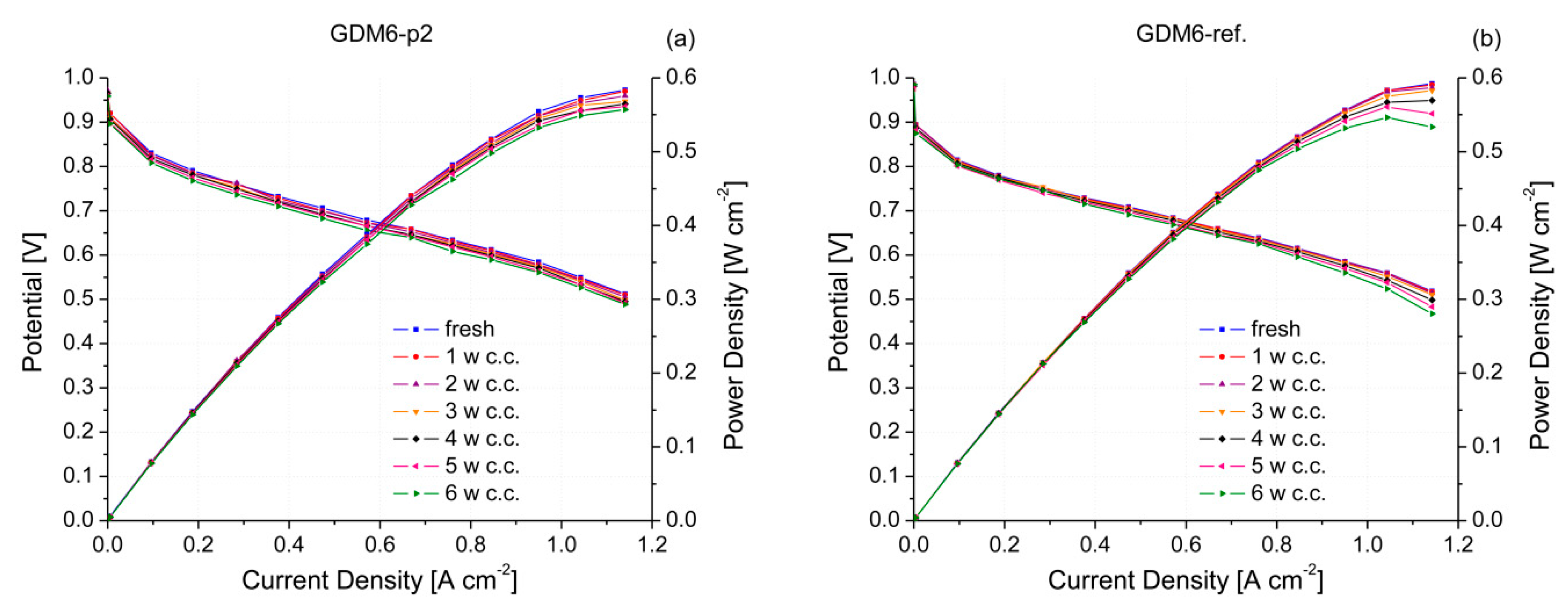
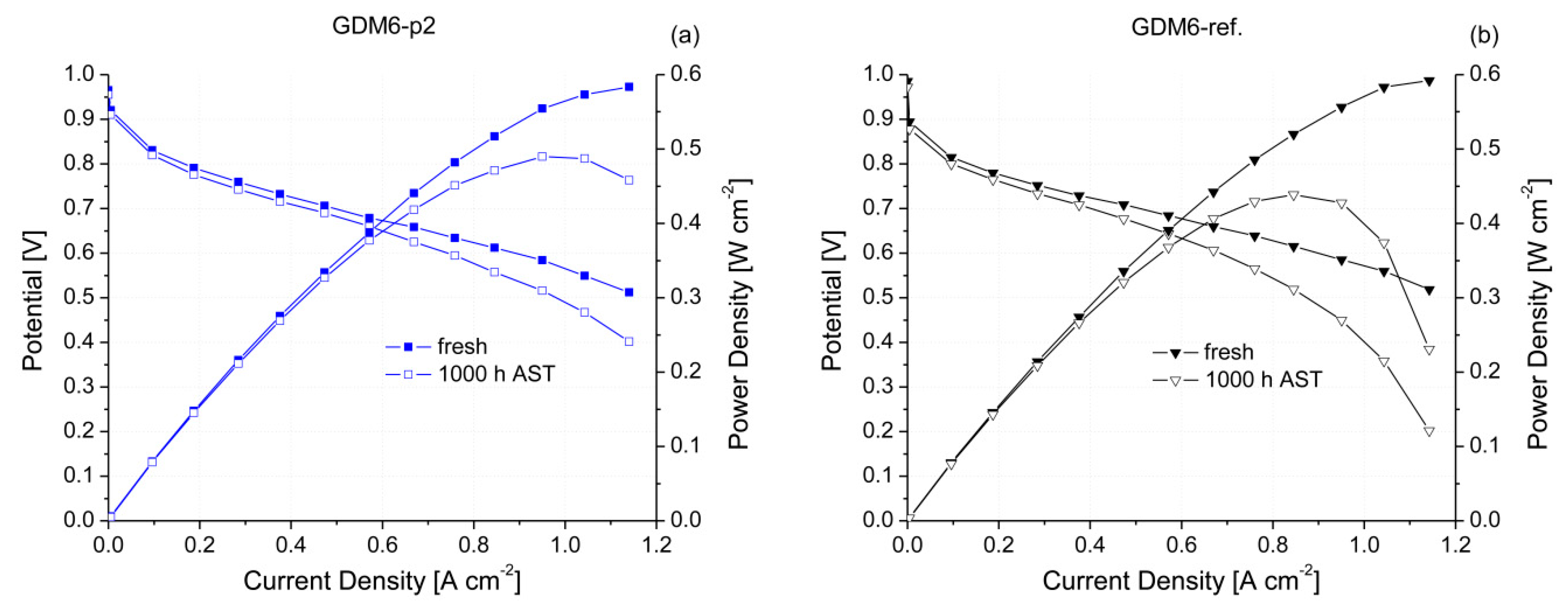
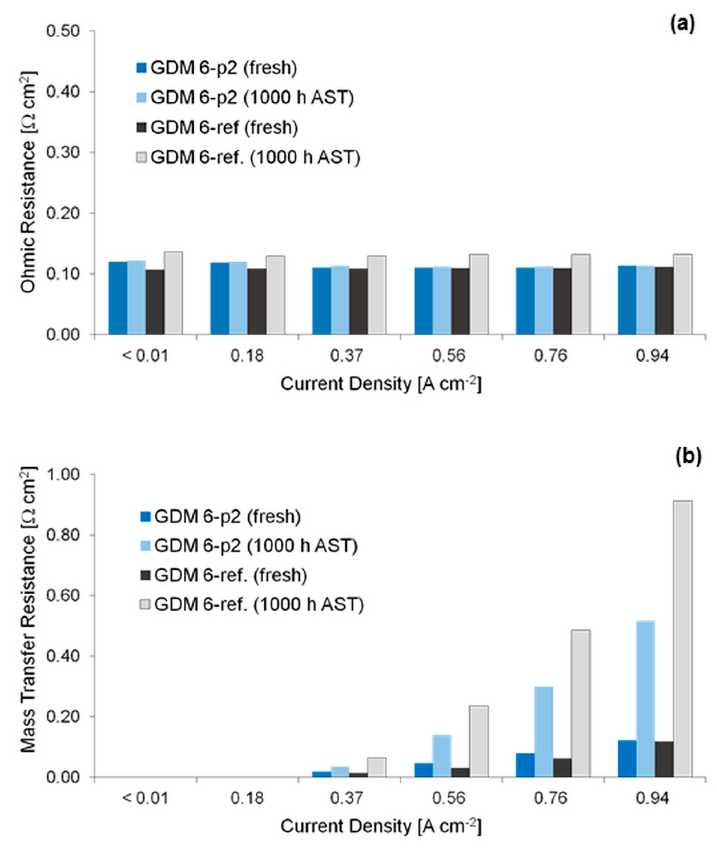
3.2. Electrochemical Characterization

Figure 3 shows the results of the electrical tests in terms of polarization and power density curves. It can be noticed that GDM6-p2 exhibited the best performance among the new prepared samples at all the operating conditions employed: both the highest output power density and the lowest slope of polarization curves in the whole range of generated current density were obtained with the fuel cell assembled with the samples. The curves related to GDM6-p2 performances are practically overlapped with the ones obtained with the benchmark; however, it is worth underlining that, in the reference sample, the GDL was PTFE-treated with a much higher polymer concentration (12 wt. % of PTFE vs. 1 wt. % of PFPE). In addition, the performances are stable on the whole range of conditions adopted for the testing, with just slight variations in terms of mass transfer resistance. This suggests that there is a proper management of the water content, independent of the operating conditions, and that the sample is not affected by significant degradation mechanisms during the short period.
The best performances of the GDM6-p3 sample were achieved at low relative humidity, with just a slight increase in ohmic losses, and mainly of losses due to concentration polarization compared to GDM6-p2. Overall, it is evident that a sharp improvement of performances for the fuel cell assembled with this sample occurs when the gas flow at the cathode features a relative humidity of 60%. This can be due to a mass transfer enhancement, considering that a reduced humidity prevents the water condensation within the cell, thus preserving the oxygen diffusivity in the cathodic compartment.
Finally, GDM6-p1 is the worst performing sample, in particular at high current density. Mass transfer losses are particularly large compared to the other samples and prevent the achievement of decent power densities, especially at 80 °C. Moreover, strong voltage drops have been recorded at medium current density, i.e., in the ohmic region, at 80 °C, which suggests a dependence of the electrolyte hydration on the operating temperature due to excessive vapor permeation through the MPL.
Figure 4 and Figure 5 show trends of both ohmic and mass transfer resistance as a function of current density. Such parameters are those mostly influenced by GDMs features, whereas charge transfer resistance is mainly dependant on the catalytic layer, which is a commercial component with fixed properties in this work; therefore, it has not been reported.
The ohmic resistances shown in Figure 4 follow similar trends under all the operating conditions. GDM6-p2 exhibits the best behavior, comparable to the one of the benchmark. The difference with the other samples may be determined by the additional PFPE coating that could reduce the permeability of the MPL, thus enhancing the accumulation of water in the electrolyte at the cathodic side: this probably has favored the back-diffusion mechanism in the MEA, so the ohmic resistance of the ionomer has been kept low due to uniform and constant hydration. Indeed, at a low-medium current density, the water removal action of the MPL is of limited importance, given the low amount of water produced at the cathodic side; however, its presence is effective in preventing the dispersion of water expelled by the ionomer—particularly at higher temperatures and a low relative humidity. Such effects point out the dual role of the MPL, which at the same time is responsible for effective water removal in order to avoid the cell flooding and for maintaining a proper level of hydration for the electrolyte. The RH decrease in the gas flow at the cathode seems to be detrimental, mainly for the less efficient samples, while GDM6-p2 is definitely on par with the benchmark from this point of view.
Figure 5 shows that the most significant distinction between the samples are ascribed to the mass transfer resistance, which is deeply related to diffusion limitations arising mainly from water production within the cell. Indeed, it can be noticed that GDM6-p1 suffers from a sharp increase in resistance even at relatively low current density. This is in accordance with the ineffective water management induced by high diffusion limitations observed for polarization curves in Figure 3, and it could be due to the lower amount of PFPE on the MPL surface compared to GDM6-p2. Moreover, the preparation route might have hindered the adherence of the MPL to the substrate leading to the formation of water films at their interface, which acts as a barrier against oxygen transport and promotes the delamination of the GDM, as suggested by the higher material loss (Table 2). It is evident that the second preparation route is more beneficial in terms of mass transfer with respect to the third as well, maybe due to the addition of PFPE in the final step of the process which could induce a more effective adhesion between MPL and GDL.
Results of the preliminary durability tests performed with GDM6-p2 and the PFPE-based reference sample are reported in Figure 6 in terms of polarization and power density curves. Electrical tests were carried out every 168 h (i.e., one week) of running at constant current density, i.e., 0.5 A cm−2. A good durability can be claimed since all the curves obtained for both samples are practically overlapped. However, a slight potential drop can be seen in the high current density region of the polarization curves obtained for the reference sample (Figure 6b). This may be traced back to a worsening of the water management capability, maybe due to the bigger macropores (Figure 2) of the GDL and to the fact that different polymers were in contact in GDL and MPL, therefore likely reducing the adhesion between the components. Indeed, the material loss upon disassembling the fuel cell, after performing the whole test, was 2.1 wt. % and 3.5 wt. % for GDM6-p2 and GDM6-ref., respectively. The bigger macropores may reduce the capillary condensation and water removal, since they can be more easily clogged by the produced water; indeed, such phenomena can be only observed at a high current density, when more water is being generated.
However, it is worth underlining that the PEMFC systems which are already commercialized produce electric energy in the ohmic region; in the region, both samples exhibited the same performance. This is also the reason why these tests were carried out at 0.5 A cm−2. So, ad-hoc accelerated stress tests (AST) are needed in order to be more accurate in predicting the resistance against degradation of such components. Figure 7 shows the polarization and power density curves after 1000 h of AST compared to those obtained for fresh samples, i.e., not subjected to AST. Obviously, the stressed samples exhibited worse performance, even though the reduction was not dramatic and the voltage values in the ohmic zone were still capable of producing acceptable efficiencies in possible real systems [4,35]. As expected, the highest loss occurred in the concentration polarization region, i.e., at a high current density, and this is due to the difficult water management caused by the partial loss of the surface carbon of the MPL upon mechanical AST. Indeed, upon disassembling the fuel cell after performing ASTs, a total weight loss of 8.2 wt. % was found for the reference sample, while a smaller loss of 2.9 wt. % was detected for GDM6-p2. This may be a further indication of a satisfying adhesion between the new MPL and its GDL substrate, and of a better resistance to degradation compared to our benchmark featuring a PFPE-based MPL deposited onto a standard PTFE-treated GDL.
This may be more understandable by analyzing the trend of ohmic and, at a higher extent, of mass transfer resistances as a function of current density (Figure 8), obtained after performing AST. The change in the ohmic resistance (Figure 8a) upon AST is not significant for the new produced sample (GDM6-p2), while a sharper increase compared to the values of the fresh sample can be noticed for the reference sample (GDM6-ref.). This may have been caused by a worse contact between the MPL and the catalyst layer due to the witnessed loss of surface material, which would lead to an increase in the contact resistance and consequently in the overall ohmic resistance.
On the other hand, an increase in mass transfer resistance (Figure 8b) is clear for both samples. This was largely expected, since mechanical degradation induced by AST has caused partial MPL material loss and worsened the capability of removing the excess water, as found in a previous work [35]. However, it is clear that the new sample was able to improve resistance to degradation and that it was damaged less than the reference sample; indeed, for GDM6-p2, a lower increase in the mass transfer resistance with respect to the fresh sample was found compared to the change in the same parameter for the benckmark, i.e., GDM6-ref. sample.

4. Conclusions

In the present work, three different preparation routes were employed to prepare perfluoropolyether (PFPE)-based GDMs, with both GDLs and MPLs treated with the same polymer. Such polymers had been already applied successfully as alternative to the currently most-used hydrophobic agent, PTFE. The main improvement introduced by the novel polymer was the chance to operate at a much lower temperature during the preparation of the GDM, and to use a lower amount of hydrophobic agent compared to PTFE.
This work mainly aimed to investigate the electrochemical performance of fuel cells assembled with novel GDMs when PFPE was used for both GDLs and MPLs, while the benchmark was a sample in which only MPL was based on PFPE, keeping PTFE as hydrophobic agent for the GDL. Moreover, the reason why different preparation routes were carried out lies in the pursuit of an effective adhesion between MPL and GDL, with the final target of improving the durability of the GDM.
It was found that the preparation method had an effect on the pores size distribution, changing the microporous and macroporous region of the obtained sample. This was reflected in the electrochemical performance, too; indeed, much better polarization curves were achieved for GDM6-p2, which showed a better compromise between porosity, wettability and adhesion. Indeed, the sample—which featured a further dipping in the polymeric dispersion during the preparation, upon the MPL deposition using the blade coating technique—exhibited a low change in the static contact angle after electrochemical tests, together with a less pronounced loss of material upon the disassembly of the fuel cell.
The durability of the best performing sample and of the PFPE-based MPL benchmark was tested by applying both constant current tests and mechanical accelerated stress tests (ASTs) for 1000 h. Fuel cell tests performed after durability experiments revealed a better resistance of the novel sample compared to the reference one against degradation, since a reduced increase in mass transfer limitations—likely due to better adhesion between the MPL and the GDL—was found.
The use of PFPE is of great interest from an economic point of view too. The GDMs production procedure is comparable to that already employed for PTFE-based components, but the amount of material is much lower (1 wt.% vs. 12 wt.% for the GDLs treatment and 6 wt.% vs. 12 wt.% for the MPLs production). In addition, the maximum temperature of the heat treatment step is lower too, thus reducing the energy consumption and process time. The durability improvement is particularly meaningful, because it may extend the service life of the fuel cell, thus reducing the costs of maintenance and waste disposal.
These promising findings may prompt further detailed studies about the possible employment of PFPE as a valid alternative to PTFE for the hydrophobic treatment of both GDLs and MPLs, aiming to reduce the temperature of the thermal treatment in the preparation route, as well as to improve the durability of the final obtained GDMs.

Author Contributions

Individual contributions are as follows: conceptualization, P.G.S., S.L. and G.D.; methodology, S.L. and P.G.S.; investigation, R.B.; data curation, R.B., S.L. and M.M.; writing—original draft preparation, R.B. and S.L.; writing—review and editing, M.M. and S.L.; supervision, G.D. All authors have read and agreed to the published version of the manuscript.

Funding

This research received no external funding.

Conflicts of Interest

The authors declare no conflict of interest.

References

  1. Omrani, R.; Shabani, B. Review of gas diffusion layer for proton exchange membrane-based technologies with a focus on unitised regenerative fuel cells. Int. J. Hydrog. Energy 2019, 44, 3834–3860. [Google Scholar] [CrossRef]
  2. Ehteshami, S.M.M.; Chan, S.H. The role of hydrogen and fuel cells to store renewable energy in the future energy network—Potentials and challenges. Energy Policy 2014, 73, 103–109. [Google Scholar] [CrossRef]
  3. Garland, N.L.; Papageorgopoulos, D.C.; Stanford, J.M. Hydrogen and fuel cell technology: Progress, challenges, and future directions. Enrgy Proced 2012, 28, 2–11. [Google Scholar] [CrossRef] [Green Version]
  4. Barbir, F. PEM Fuel Cells: Theory and Practice, 2nd ed.; Academic Press: London, UK, 2013; p. 444. [Google Scholar]
  5. Peighambardoust, S.J.; Rowshanzamir, S.; Amjadi, M. Review of the proton exchange membranes for fuel cell applications. Int. J. Hydrog. Energy 2010, 35, 9349–9384. [Google Scholar] [CrossRef]
  6. Wang, Y.; Chen, K.S.; Mishler, J.; Cho, S.C.; Adroher, X.C. A review of polymer electrolyte membrane fuel cells: Technology, applications, and needs on fundamental research. Appl. Energy 2011, 88, 981–1007. [Google Scholar] [CrossRef] [Green Version]
  7. Wan, Z.M.; Chang, H.W.; Shu, S.M.; Wang, Y.X.; Tang, H.L. A Review on Cold Start of Proton Exchange Membrane Fuel Cells. Energies 2014, 7, 3179–3203. [Google Scholar] [CrossRef] [Green Version]
  8. Omrani, R.; Shabani, B. Gas diffusion layer modifications and treatments for improving the performance of proton exchange membrane fuel cells and electrolysers: A review. Int. J. Hydrog. Energy 2017, 42, 28515–28536. [Google Scholar] [CrossRef]
  9. Leeuwner, M.J.; Patra, A.; Wilkinson, D.P.; Gyenge, E.L. Graphene and reduced graphene oxide based microporous layers for high-performance proton-exchange membrane fuel cells under varied humidity operation. J. Power Sources 2019, 423, 192–202. [Google Scholar] [CrossRef]
  10. Park, S.; Lee, J.W.; Popov, B.N. A review of gas diffusion layer in PEM fuel cells: Materials and designs. Int. J. Hydrog. Energy 2012, 37, 5850–5865. [Google Scholar] [CrossRef]
  11. Morgan, J.M.; Datta, R. Understanding the gas diffusion layer in proton exchange membrane fuel cells. I. How its structural characteristics affect diffusion and performance. J. Power Sources 2014, 251, 269–278. [Google Scholar] [CrossRef]
  12. Mariani, M.; Latorrata, S.; Stampino, P.G.; Dotelli, G. Evaluation of Graphene Nanoplatelets as a Microporous Layer Material for PEMFC: Performance and Durability Analysis. Fuel Cells 2019, 19, 685–694. [Google Scholar] [CrossRef]
  13. Chang, H.M.; Lin, C.W.; Chang, M.H.; Shiu, H.R.; Chang, W.C.; Tsau, F.H. Optimization of polytetrafluoroethylene content in cathode gas diffusion layer by the evaluation of compression effect on the performance of a proton exchange membrane fuel cell. J. Power Sources 2011, 196, 3773–3780. [Google Scholar] [CrossRef]
  14. Gurau, V.; Bluemle, M.J.; De Castro, E.S.; Tsou, Y.M.; Mann, J.A.; Zawodzinski, T.A. Characterization of transport properties in gas diffusion layers for proton exchange membrane fuel cells—1. Wettability (internal contact angle to water and surface energy of GDL fibers). J. Power Sources 2006, 160, 1156–1162. [Google Scholar] [CrossRef]
  15. Gurau, V.; Bluemle, M.J.; De Castro, E.S.; Tsou, Y.M.; Zawodzinski, T.A.; Mann, J.A. Characterization of transport properties in gas diffusion layers for proton exchange membrane fuel cells 2. Absolute permeability. J. Power Sources 2007, 165, 793–802. [Google Scholar] [CrossRef]
  16. Wang, Y.; Wang, C.Y.; Chen, K.S. Elucidating differences between carbon paper and carbon cloth in polymer electrolyte fuel cells. Electrochim. Acta 2007, 52, 3965–3975. [Google Scholar] [CrossRef]
  17. Ozden, A.; Shahgaldi, S.; Li, X.G.; Hamdullahpur, F. A graphene-based microporous layer for proton exchange membrane fuel cells: Characterization and performance comparison. Renew Energy 2018, 126, 485–494. [Google Scholar] [CrossRef]
  18. Alink, R.; Gerteisen, D. Modeling the Liquid Water Transport in the Gas Diffusion Layer for Polymer Electrolyte Membrane Fuel Cells Using a Water Path Network. Energies 2013, 6, 4508–4530. [Google Scholar] [CrossRef] [Green Version]
  19. Lee, J.; Liu, H.; George, M.G.; Banerjee, R.; Ge, N.; Chevalier, S.; Kotaka, T.; Tabuchi, Y.; Bazylak, A. Microporous layer to carbon fibre substrate interface impact on polymer electrolyte membrane fuel cell performance. J. Power Sources 2019, 422, 113–121. [Google Scholar] [CrossRef]
  20. Latorrata, S.; Stampino, P.G.; Cristiani, C.; Dotelli, G. Performance Evaluation and Durability Enhancement of FEP-Based Gas Diffusion Media for PEM Fuel Cells. Energies 2017, 10, 2063. [Google Scholar] [CrossRef] [Green Version]
  21. Kitahara, T.; Nakajima, H.; Mori, K. Hydrophilic and hydrophobic double microporous layer coated gas diffusion layer for enhancing performance of polymer electrolyte fuel cells under no-humidification at the cathode. J. Power Sources 2012, 199, 29–36. [Google Scholar] [CrossRef]
  22. Leeuwner, M.J.; Wilkinson, D.P.; Gyenge, E.L. Novel Graphene Foam Microporous Layers for PEM Fuel Cells: Interfacial Characteristics and Comparative Performance. Fuel Cells 2015, 15, 790–801. [Google Scholar] [CrossRef]
  23. Weber, A.Z.; Newman, J. Effects of microporous layers in polymer electrolyte fuel cells. J. Electrochem. Soc. 2005, 152, A677–A688. [Google Scholar] [CrossRef]
  24. Park, S.; Popov, B.N. Effect of hydrophobicity and pore geometry in cathode GDL on PEM fuel cell performance. Electrochim. Acta 2009, 54, 3473–3479. [Google Scholar] [CrossRef]
  25. Wong, A.K.C.; Ge, N.; Shrestha, P.; Liu, H.; Fahy, K.; Bazylak, A. Polytetrafluoroethylene content in standalone microporous layers: Tradeoff between membrane hydration and mass transport losses in polymer electrolyte membrane fuel cells. Appl. Energy 2019, 240, 549–560. [Google Scholar] [CrossRef]
  26. Shrestha, P.; Ouellette, D.; Lee, J.; Ge, N.; Kai, A.; Wong, C.; Muirhead, D.; Liu, H.; Banerjee, R.; Bazylak, A. Graded Microporous Layers for Enhanced Capillary-Driven Liquid Water Removal in Polymer Electrolyte Membrane Fuel Cells. Adv. Mater. Interfaces 2019, 6, 1901157. [Google Scholar] [CrossRef]
  27. Balzarotti, R.; Latorrata, S.; Stampino, P.G.; Cristiani, C.; Dotelli, G. Development and Characterization of Non-Conventional Micro-Porous Layers for PEM Fuel Cells. Energies 2015, 8, 7070–7083. [Google Scholar] [CrossRef] [Green Version]
  28. Latorrata, S.; Balzarotti, R.; Stampino, P.G.; Cristiani, C.; Dotelli, G.; Guilizzoni, M. Design of properties and performances of innovative gas diffusion media for polymer electrolyte membrane fuel cells. Prog. Org. Coat. 2015, 78, 517–525. [Google Scholar] [CrossRef]
  29. Yuan, X.Z.; Song, C.; Wang, H.; Zhang, J. Electrochemical Impedance Spectroscopy in PEM Fuel Cells: Fundamentals and Applications; Springer: London, UK, 2010; pp. 1–420. [Google Scholar]
  30. Latorrata, S.; Pelosato, R.; Stampino, P.G.; Cristiani, C.; Dotelli, G. Use of Electrochemical Impedance Spectroscopy for the Evaluation of Performance of PEM Fuel Cells Based on Carbon Cloth Gas Diffusion Electrodes. J. Spectrosc. 2018, 2018, 3254375. [Google Scholar] [CrossRef] [Green Version]
  31. Asghari, S.; Mokmeli, A.; Samavati, M. Study of PEM fuel cell performance by electrochemical impedance spectroscopy. Int. J. Hydrog. Energy 2010, 35, 9283–9290. [Google Scholar] [CrossRef]
  32. Wagner, N. Characterization of membrane electrode assemblies in polymer electrolyte fuel cells using a.c. impedance spectroscopy. J. Appl. Electrochem. 2002, 32, 859–863. [Google Scholar] [CrossRef]
  33. Dhirde, A.M.; Dale, N.V.; Salehfar, H.; Mann, M.D.; Han, T.H. Equivalent Electric Circuit Modeling and Performance Analysis of a PEM Fuel Cell Stack Using Impedance Spectroscopy. IEEE Trans. Energy Convers. 2010, 25, 778–786. [Google Scholar] [CrossRef]
  34. Ramasamy, R.P.; Kumbur, E.C.; Mench, M.M.; Liu, W.; Moore, D.; Murthy, M. Investigation of macro- and micro-porous layer interaction in polymer electrolyte fuel cells. Int. J. Hydrog. Energy 2008, 33, 3351–3367. [Google Scholar] [CrossRef]
  35. Latorrata, S.; Stampino, P.G.; Cristiani, C.; Dotelli, G. Development of an optimal gas diffusion medium for polymer electrolyte membrane fuel cells and assessment of its degradation mechanisms. Int. J. Hydrog. Energy 2015, 40, 14596–14608. [Google Scholar] [CrossRef]
  36. Wang, X.L.; Zhang, H.M.; Zhang, J.L.; Xu, H.F.; Zhu, X.B.; Chen, J.; Yi, B.L. A bi-functional micro-porous layer with composite carbon black for PEM fuel cells. J. Power Sources 2006, 162, 474–479. [Google Scholar] [CrossRef]
Figure 1. Schematic representation of GDMs production processes (same color corresponds to the same unit operation/step).
Energies 13 01831 g001
Figure 2. Pores size distribution of the prepared GDMs and the reference sample (a) and enlargement of the micro-porous region (b).
Energies 13 01831 g002
Figure 3. Polarization and power density curves obtained with fuel cells assembled with prepared PFPE-based GDMs. Operating conditions: 60 °C and RH (A–C) 80–100% (a), 60 °C and RH (A–C) 80–60% (b), 80 °C and RH (A–C) 80–100% (c), 80 °C and RH (A–C) 80–60% (d).
Energies 13 01831 g003
Figure 4. Trend of ohmic resistance as a function of current density obtained with fuel cells assembled with prepared PFPE-based GDMs. Operating conditions: 60 °C and RH (A-C) 80–100% (a), 60 °C and RH (A-C) 80–60% (b), 80 °C and RH (A-C) 80–100% (c), 80 °C and RH (A-C) 80–60% (d).
Energies 13 01831 g004
Figure 5. Trend of mass transfer resistance as a function of current density obtained with fuel cells assembled with prepared PFPE-based GDMs. Operating conditions: 60 °C and RH (A-C) 80–100% (a), 60 °C and RH (A-C) 80–60% (b), 80 °C and RH (A-C) 80–100% (c), 80 °C and RH (A-C) 80–60% (d).
Energies 13 01831 g005
Figure 6. Polarization and power density curves obtained every week of constant current durability tests for GDM6-p2 (a) and GDM6-ref. (b) GDMs. Operating condition: 60 °C and RH (A-C) 80–100%.
Energies 13 01831 g006
Figure 7. Polarization and power density curves obtained upon 1000 h of accelerated stress tests for GDM6-p2 (a) and GDM6-ref. (b) compared to curves obtained for fresh (as prepared) samples. Operating condition: 60 °C and RH (A-C) 80–100%.
Energies 13 01831 g007
Figure 8. Trend of ohmic resistance (a) and mass transfer resistance (b) as a function of current density obtained for fresh samples (not subjectd to AST) and upon 1000 h of accelerated stress tests. Operating condition: 60 °C and RH (A-C) 80–100%.
Energies 13 01831 g008
Table 1. Resume of the prepared samples: details on production path, hydrophobic agent and polymer content in both GDL and MPL.
SampleGDLMPLProduction Process
Hydrophobic AgentContent [wt. %]Hydrophobic AgentContent [wt. %]
GDM6-p1PFPE1PFPE6Path 1
GDM6-p2PFPE1PFPE6Path 2
GDM6-p3PFPE1PFPE6Path 3
GDM6-ref. 1PTFE12PFPE6reference 1
1 reference [27].
Table 2. Measured values of static contact angle (C.A.) for GDM samples (BCT: before cell test, ACT: after cell test) and weight loss after cell tests.
SampleC.A. BCT [°]C.A. ACT [°]Loss ACT [wt. %]
AnodeCathode
GDM6-p1152 ± 3124 ± 9152 ± 49.2
GDM6-p2151 ± 2149 ± 5149 ± 30.9
GDM6-p3150 ± 3153 ± 3153 ± 45.7
GDM6-ref. [27]146 ± 5154 ± 3145 ± 21.0

