Article

Ruthenium (Ru) Doped Titanium Dioxide (P25) Electrode for Dye Sensitized Solar Cells

by
Tharmakularasa Rajaramanan
1,2,3,
Muthukumarasamy Natarajan
4,
Punniamoorthy Ravirajan
2,
Meena Senthilnanthanan
3,* and
Dhayalan Velauthapillai
1,*
1
Faculty of Engineering and Science, Western Norway University of Applied Sciences, P.O. Box 7030, 5020 Bergen, Norway
2
Clean Energy Research Laboratory, Department of Physics, University of Jaffna, Jaffna 40000, Sri Lanka
3
Department of Chemistry, University of Jaffna, Jaffna 40000, Sri Lanka
4
Department of Physics, Coimbatore Institute of Technology, Coimbatore, Tamil Nadu 641014, India
*
Authors to whom correspondence should be addressed.
Energies 2020, 13(7), 1532; https://doi.org/10.3390/en13071532
Submission received: 28 February 2020 / Revised: 19 March 2020 / Accepted: 22 March 2020 / Published: 25 March 2020
(This article belongs to the Section A2: Solar Energy and Photovoltaic Systems)

Abstract

:
In this study, P25-titanium dioxide (TiO2) was doped with ruthenium (Ru) by systematically varying the Ru content at 0.15, 0.30, 0.45 and 0.6 mol%. The synthesized Ru-doped TiO2 nanomaterials have been characterized by X-ray diffraction (XRD), Raman spectroscopy, energy-dispersive X-ray (EDX) analysis, UV-visible (UV–Vis) spectroscopy, and electrochemical impedance (EIS) spectroscopy. The XRD patterns of undoped and Ru-doped TiO2 nanomaterials confirm the presence of mixed anatase and rutile phases of TiO2 while EDX spectrum confirms the presence of Ti, O and Ru. Further, UV-visible absorption spectra of doped TiO2 nanomaterial reveal a slight red shift on Ru-doping. The short circuit current density (JSC) of the cells fabricated using the Ru-doped TiO2 photoanode was found to be dependent on the amount of Ru present in TiO2. Optimized cells with 0.3 mol% Ru-doped TiO2 electrodes showed efficiency which is 20% more than the efficiency of the control cell (η = 5.8%) under stimulated illumination (100 mWcm−2, 1 sun) with AM 1.5 filter. The increase in JSC resulted from the reduced rate of recombination upon doping of Ru and this was confirmed by EIS analysis.

Graphical Abstract

1. Introduction

Dye-sensitized solar cells (DSSCs) have been studied intensively as an alternative energy source due to their low cost, easy fabrication and more environmentally friendly nature. A DSSC consists of an electron transporting mesoporous metal oxide layer on a transparent conducting oxide coated glass, dye, electrolyte and a counter electrode. Generally, the visible light is converted into electricity in DSSCs through spectral sensitization of wide bandgap semiconductors such as SnO2 [1], SrTiO3 [2], Nb2O5 [3], ZnO [4] and TiO2 [5]. Among the semiconductors explored for DSSCs so far, TiO2 remains the most promising material [1]. Although natural dyes used as sensitizers in DSSC are cheap compared to synthetic dyes, their reported efficiencies are rather low [6,7,8,9]. The concept of a dye-sensitized solid-state solar cell was first proposed by Tennakone et al. in 1988 [10] and then O’Regan and Grätzel reported an efficiency of 7.1% and a current density greater than 12 mAcm−2 for DSSC in which I / I 3 redox couple and TiO2 were used as liquid electrolyte and ETM, respectively [5]; later, the maximum efficiency of 11.1% was reported by Nazeeruddin et al. [11,12]. However, relaxation of oxidized dye and recombination processes connected to the charge carriers hinder the performance of DSSCs. One of the alternative strategies to reduce the above said problem in DSSCs is the use of doped TiO2 electrode. It is evident that dopant materials narrow the bandgap and increase the charge traps of TiO2 and hence modify the properties, such as conduction band energy, charge transport, recombination and collection of charge carriers [13]. Different dopants, such as transition metals, alkali earth metals [14,15], non-metals [16,17], and rare earth elements [14,18], have been employed; but the incorporation of transition metals into TiO2 gives rise to the formation of a wide range of new energy levels arising from the partially filled d-orbitals of transition metals close to the conduction band (CB) of TiO2, that leads to a reduction in the bandgap and enhancement in harvesting visible light. This makes transition metals suitable for tuning the CB structure [13].
Various transition metals (Ag [19,20], Co [21], Mn [21], Zn [22], Cr [23], Nb [24], W [25], Cu [26], Y [27] and Sc [28]) have been used as dopant in TiO2. Ruthenium (Ru) appears to be a good dopant as the Ru4+ ion has an ionic radius of 0.062 nm which is comparable to that of Ti4+ ion (0.061 nm) [29]. The utilization of Ru-doped TiO2 as ETM in DSSCs has not yet been studied in depth. In 2009, Houskova et al. reported that Ru-doping decreases the bandgap of TiO2 [30], while a contradictory observation was reported by Kong et al. in 2015 [31]. In another study, So and co-workers (2012) reported η of 5.2% using 0.02 at.% Ru-doped TiO2 nanotube layers in DSSC [32]. Lu et al. (2016) achieved η of 5.39% for the Ru-doped TiO2 [33]. However, the use of Ru-doped P25-TiO2 (Degussa P25—commercially purchased TiO2 nanopowder) as a mesoporous metal oxide in DSSCs has not been reported so far, although Ru-doped P25-TiO2 has been widely employed to enhance photocatalytic activities [34,35,36].
In this study, RuCl3·xH2O was used as a precursor to synthesize Ru-doped electrodes and their performances in DSSCs were investigated by systematically varying the Ru content. The synthesised Ru-doped TiO2 was characterized by XRD, Raman, UV–visible, EDX and EIS spectroscopy studies.

2. Materials and Methods

2.1. Materials

All reagents and solvents used were obtained from commercial sources; absolute ethanol (>99%, Sigma Aldrich), Triton TM X-100 (laboratory grade, Sigma-Aldrich), ruthenium (III) chloride hydrate (Reagent Plus-grade, Sigma-Aldrich), titanium dioxide nanopowder (21 nm primary particle size, ≥99.5% trace metals basis, Sigma-Aldrich), di-tetrabutylammonium cis-bis(isothiocyanato)bis(2,2′-bipyridyl-4,4′-dicarboxylato)ruthenium(II) dye (95%, Sigma-Aldrich), acetonitrile (Gradient grade, Sigma-Aldrich), tert-butyl alcohol (≥99.7%, Sigma-Aldrich), acetylacetone (≥99.5%, Fluka Analytical).

2.2. Methods

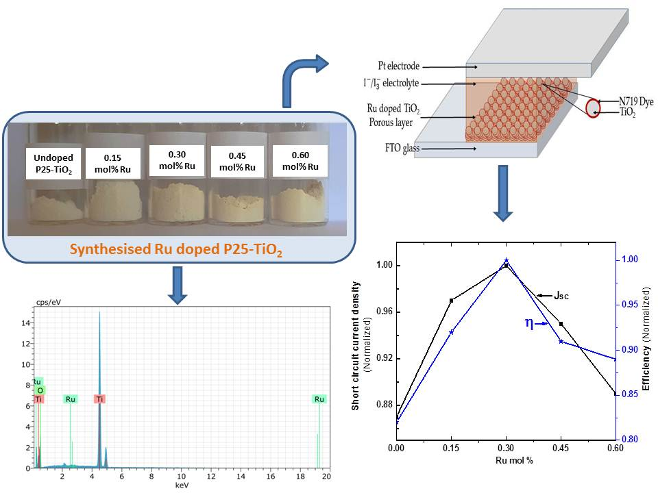
2.2.1. Preparation of Ru-Doped TiO2 Nanomaterials

To achieve a reproducible outcome and comparison, a simple doping of Ru in P25-TiO2 was used to prepare Ru-doped TiO2 nanomaterials. Then 0.15, 0.3, 0.45 and 0.6 mol% of RuCl3·xH2O were added to the TiO2 nanopowder (P25) and stirred vigorously for one hour at room temperature (step 1, 2) and then it was dried at 100 °C with continuous stirring for 2 hours (step 3). The product was ground well (step 4) and the resulting Ru-TiO2 powder mixtures were annealed at 500 °C for 3 h (step 5) (Figure 1) [26,35,37,38].

2.2.2. Fabrication of DSSCs

The fluorine-doped tin oxide (FTO) coated conducting glass (sheet resistance 7.5 Ω/cm2) was used as the current collector. It was cleaned initially with soap water and subsequently with distilled water and ethanol using an ultrasonic bath. Then, the synthesized Ru-doped TiO2 nanomaterial was made into paste by mixing with deionized water, acetylacetone and Triton TM X-100 binder and coated on FTO by the doctor-blade technique using a glass rod with adhesive tapes (3 M Scotch tapes) as spacers and the thickness of the TiO2 film was about 7 μm. The prepared Ru-doped TiO2 films were dried and calcinated at 500 °C for 30 minutes. Then the coated glasses were soaked in 0.3 mM solution of N719 dye in acetonitrile/tert-butyl alcohol (50%v/v) for 12 h. After the dye-sensitization process, the photoanode was washed with acetonitrile to remove the unanchored dye molecules and dried. A platinum-coated FTO glass plate was used as the counter electrode. The dye-coated Ru-doped TiO2 electrode and Pt counter electrode [26] were used to assemble the cell and I / I 3 electrolyte was used as redox electrolyte.

2.2.3. Characterization

The structural properties of the synthesized nanomaterials were studied by the X-ray diffraction method using scan range (2θ) between 20° and 95° with step size of 0.02° and scan speed of 1°/min. A Raman spectroscopic study was carried out using a laser confocal Raman microscope (Renishaw, UK, Model: Invia). The optical absorbance spectra were recorded using Shimadzu 1800 Scanning Double Beam UV-visible spectrophotometer. The elemental composition of the synthesized nanomaterials was analyzed by the energy-dispersive X-ray spectroscopy technique. The photovoltaic performance of the cells was studied using Keithley-2400 source measurement unit (SMU) under simulated irradiation of intensity 100 mWcm−2 with AM 1.5 filter (Peccell-PEC-L12, Japan). Current–voltage (I–V) characteristics in the dark were measured before and after the illumination which confirmed no change in device behaviour [39,40]. The effective area of the photoelectrode was 0.25 cm2. Electrochemical impedance spectroscopy (EIS) measurements were carried out on the DSSCs using Metrohm Autolab potentiostat/galvanostat (PGSTAT 128N) with a frequency response analyzer (FRA 32M).

3. Results and Discussion

3.1. X-ray Siffraction and Raman Spectroscopy

The crystal structure of the synthesized nanomaterials was investigated by the X-ray diffraction method (XRD). Figure 2 represents the XRD patterns of undoped TiO2 electrode, 0.15, 0.3, 0.45 and 0.6 mol% Ru-doped TiO2 electrodes and diffraction peaks for 2θ diffraction angles were monitored between 20° and 80°. The major peaks are observed at 25.2°, 37.6°, 48.2°, 53.7°, 55°, 62.5°, 68.5°, 70.2° and 74.89° and they correspond to the reflection planes of (101), (004), (200), (105), (211), (204), (116), (220) and (215) which confirms the presence of well-crystallized pure anatase TiO2 phase and peaks at 27.39°, 36.07° and 41.2° correspond to the reflection planes of (110), (101) and (111) for minor rutile TiO2 phase. This indicates that the anatase and rutile crystal structures are retained even after the TiO2 being doped with Ru. The average crystallite size was calculated by the Scherrer Equation [15]
d = k λ B C o s θ
where d is the crystallite size, k is a dimensionless shape factor which has a typical value of about 0.89, λ is the X-ray wavelength of Cu (0.5406 nm), θ is the Bragg angle corresponding to the anatase (101) peak, and B is the line broadening at half the maximum intensity (FWHM). The average crystallite size of undoped TiO2, 0.15, 0.3, 0.45 and 0.6 mol% Ru-doped TiO2 nanomaterials were 17.34, 17.34, 17.79, 17.56 and 17.34 nm and no significant change was observed in the crystallite size. Phase transformation from anatase to rutile was not observed on Ru-doping and hence the crystallite size remains the same. Ismael et al. reported that doping of Ru into the TiO2 lattice does not change the TiO2 crystal structure but the predominant anatase peaks of Ru-doped TiO2 are shifted slightly towards lower 2θ values when the ruthenium dopant is incorporated in TiO2 lattice [41]. Ionic radii of Ru4+ and Ti4+ are 0.062 and 0.061 nm, respectively. As both the ions have almost the same ionic radii, in the Ru-doped TiO2, the incorporated ruthenium ions may be substituting for titanium ions in the lattice. However, crystallite peaks of Ru could not be clearly observed in Ru-doped TiO2 which may be due to low mol% of the dopant and similar observations have been reported by Senthilnanthan et al. (2010) and Elezović et al. (2013) [35,42].
Figure 3a shows the Raman spectra obtained for the undoped TiO2 and Ru-doped TiO2 nanomaterials. The Raman spectrum of the undoped TiO2 nanoparticles was dominated with five bands corresponding to the six Raman active modes. Well resolved TiO2 Raman peaks with the D4h space group at about 170, 216, and 657 cm−1 (Eg), 539 cm−1 (A1g + B1g), and 420 cm−1 (B1g) were observed which correspond to the anatase phase of TiO2 [43]. Figure 3b shows that the peak intensity became weak and also the peak became broader with the increase in the percentage of Ru-doping. In general, the Raman line shape, intensity and position are strongly influenced by lattice strain, defects, and the crystallite size and shape. There was no peak for the Ru and the same behaviour is observed in the XRD studies. This suggests that Ru ions have been successfully incorporated in the TiO2 lattice.

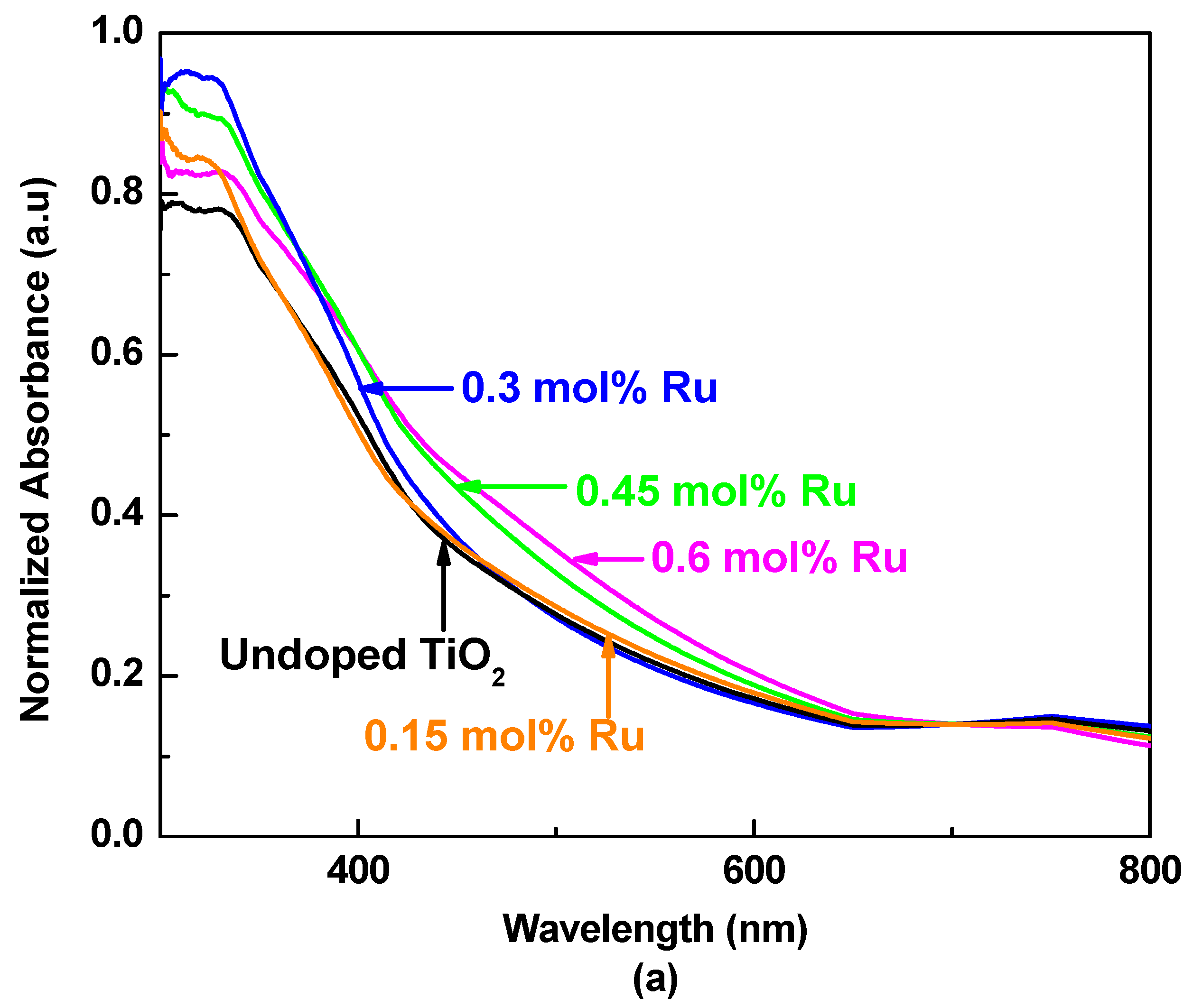
3.2. UV–Visible Absorption Spectroscopy

UV–visible spectroscopy was employed to study the optical properties of the prepared nanomaterials. Five milligrams of the nanomaterial was dispersed in 100 ml of the deionized water in an ultrasonic bath and 1 ml of the dispersed sample was transferred to a standard quartz cuvette for measurement [23]. Figure 4a represents the optical absorption spectra of undoped TiO2, 0.15, 0.3, 0.45 and 0.6 mol% Ru-doped TiO2 nanomaterials. As can be seen from Figure 4a the absorption peak of undoped TiO2 nanomaterial appears in the UV region whereas there is a slight red shift in the absorption spectrum of Ru-doped TiO2 and this red shift is found to increase with the increase in Ru-doping indicating the bandgap narrowing due to the introduction of a mid-bandgap or impurity levels located between the valence band and the conduction band of TiO2. In addition, the light absorption in the range from 400 to 700 nm is found to increase with increasing Ru content in the Ru-doped TiO2, accompanied with a change in the colour from white to reddish black [41]. The bandgap (Eg) of undoped TiO2, 0.15, 0.3, 0.45 and 0.6 mol% Ru-doped TiO2 nanomaterials was calculated using Tauc plots, where the intercept of the tangent to the plot (α)2 versus gives a good estimation of the direct bandgap for a semiconductor. The optical absorbance coefficient of a semiconductor for direct transition is given by the equation
α = A ( h υ E g ) n h υ
where = photon energy, α = absorbance coefficient, Eg = bandgap energy, A = constant and the exponent ‘n’ depends on the type of transition and it may have values of 1/2, 2, 3/2 and 3, corresponding to the allowed direct, allowed indirect, forbidden direct and forbidden indirect transitions, respectively. As shown in the Figure 4b, undoped TiO2, 0.15, 0.3, 0.45 and 0.6 mol% Ru-doped TiO2 nanomaterials have bandgap values of 3.16, 3.12, 3.05, 3.02 and 2.98 eV, respectively (straight-line intercept to the energy axis). The reduction in bandgap can be attributed to the insertion of Ru into the TiO2 lattice. Since the lower edge of the CB is made up of Ti4+ 3d bands [15], the substitution of Ti4+ with the Ru cation might have affected the CB structure. A similar observation has been reported by Wang et al., Lu et al. and Ismael et al. [29,33,41].

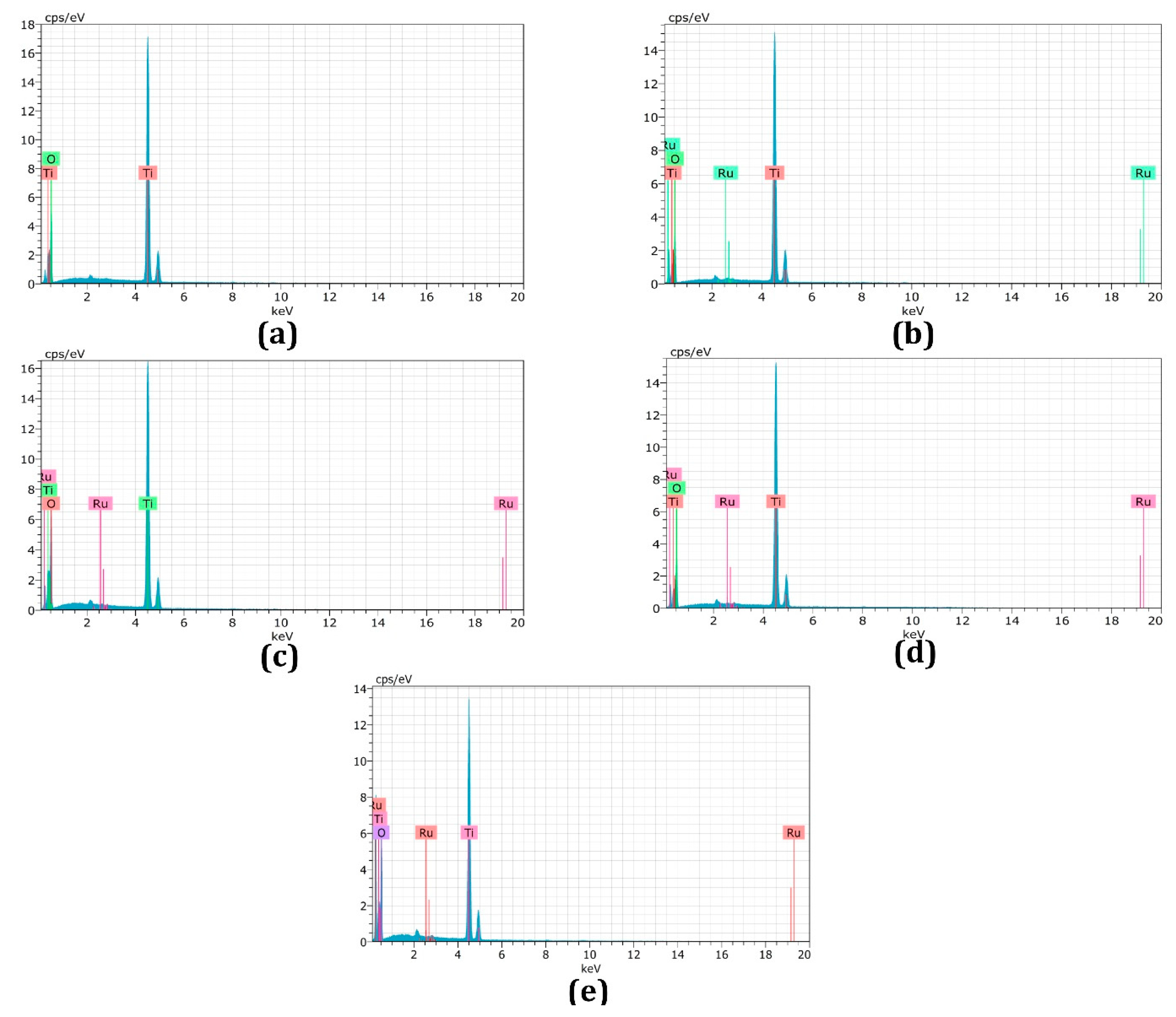
3.3. Energy-Dispersive X-ray Spectroscopy

Figure 5 illustrates the elemental analysis of the undoped and Ru-doped TiO2 samples, studied using energy-dispersive X-ray spectroscopy in the binding energy region of 0.0–20.0 KeV and the results are summarized in Table 1, which reveals the existence of Ti, O and Ru elements in Ru-doped TiO2.

3.4. J–V Characteristics

Figure 6a represents the J–V characteristics of DSSCs (in each type four devices were made and readings of the champion cells have been reported) made of photoanodes containing TiO2 electrodes doped with different mol% of Ru and its control under simulated irradiation intensity of 100 mWcm−2 with AM 1.5 filter. The corresponding photovoltaic parameters such as the short circuit current density (JSC), open-circuit photovoltage (VOC), fill factor (FF) and power conversion efficiency (η) of these cells with Ru-doped TiO2 electrodes and undoped TiO2 electrode are summarized in Table 2. Moreover, Figure 6b indicates the influence of different Ru mol% dopant on JSC and η. Ru-doping produces little improvement in VOC and FF. The control cell showed VOC of 0.66 V, which slightly increased to 0.69 V when 0.3 mol% Ru was doped. When the mol% of Ru dopant increases, Jsc shows a slight increase from 12.9 to 14.42 mAcm−2 up to 0.15 mol% Ru and then it attains a maximum of 14.73 mA/cm2 for 0.3 mol% Ru, subsequently, the JSC values show a downward trend with further increase in Ru mol%. A similar trend was reflected in the η versus Ru mol% plot. The overall efficiency of the cell is mainly influenced by JSC. Similar observations have been reported by So and co-workers (2012) in DSSCs with Ru-doped TiO2 nanotubes [32]. In our study, the cell fabricated with 0.3 mol% Ru-doped TiO2 electrode showed the best η of 7% which is over 20% enhancement relative to undoped TiO2 based DSSC (η = 5.78%).

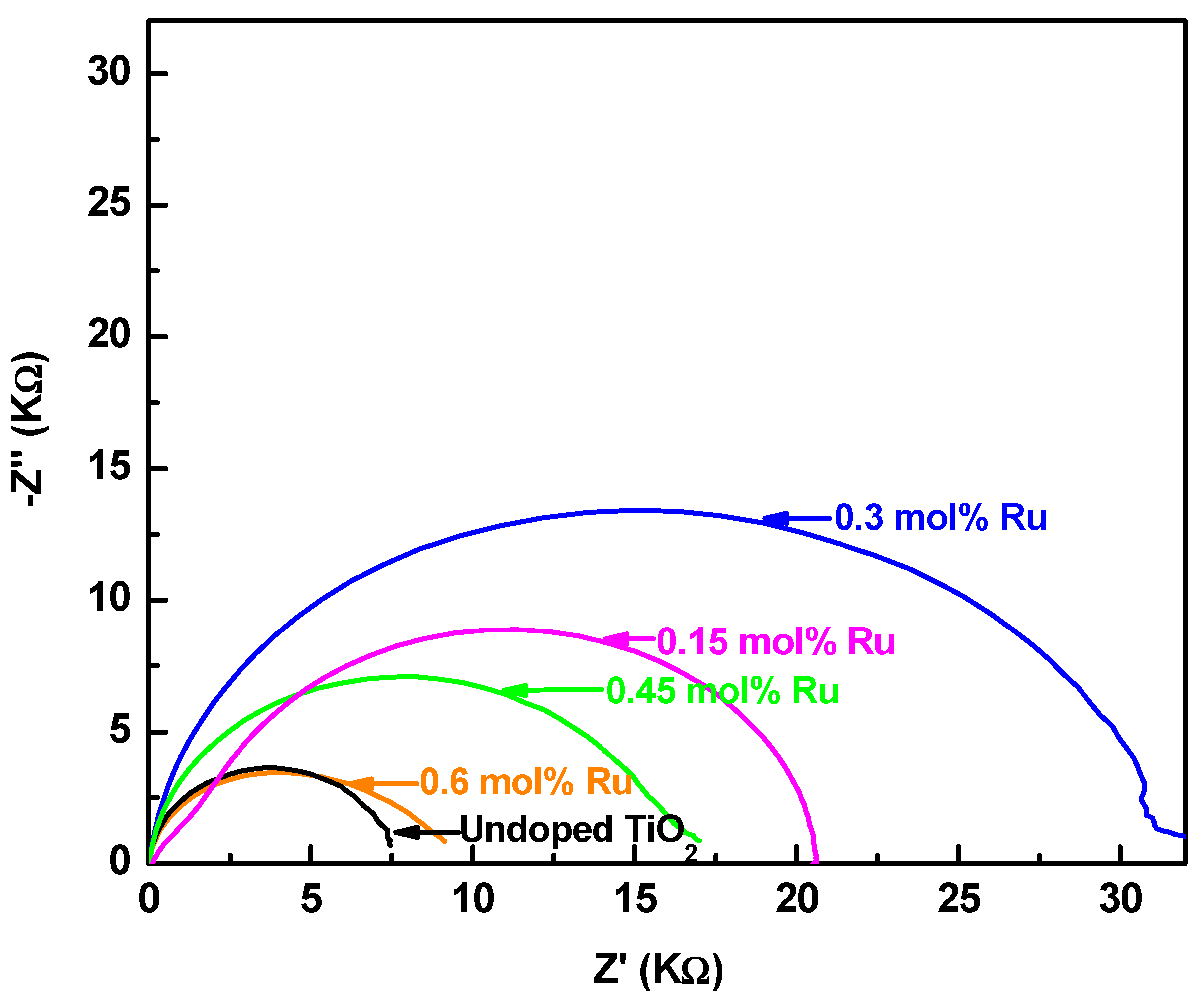
3.5. Electrochemical Impedance Spectroscopy

The interfacial charge transport phenomena of the DSSCs can be studied using electrochemical impedance spectroscopy (EIS). Figure 7 shows the Nyquist plots of the electrochemical impedance spectra of DSSCs based on the control and 0.15, 0.3, 0.45 and 0.6 mol% Ru-doped TiO2 photoanodes, which were measured at frequencies from 10−2 to 106 Hz in the dark, with a bias applied voltage of 10 mV [24]. The small semicircle in the high-frequency range corresponds to the charge transfer resistance (R1), which is related to the charge transfer at the interface of the electrolyte/Pt counter electrode and FTO/TiO2 interface. A larger semicircle in the low frequency region is mainly related to the charge recombination resistance (R2) across the TiO2/electrolyte interface with a partial contribution from electron transport and accumulation in TiO2 photoanode [44]. R1 and R2 values can be estimated from the diameter of the semicircles and resistance related to electron recombination (R2) increases with Ru-doping up to 0.3 mol% and then it starts to decrease with the increase in concentration of Ru. The higher values of resistance related to electron recombination indicate reduced electron recombination in Ru-doped electrodes [45]. This is the reason for the higher Jsc values for the Ru-doped devices in the J–V measurement [32] even though increased recombination resistance and reduced recombination rate improve the Voc of the Ru-doped devices, this can also be attributed to the reduction in the bandgap as well [15]. A similar observation was reported by Wang et al. in perovskite solar cells [29] and also Ismael et al. (2019) reported that Ru-doping could facilitate the separation and migration of photogenerated electron–hole pairs [41].

4. Conclusions

In the present study, Ru-doped TiO2 electrodes were fabricated by treating TiO2 with RuCl3·xH2O and by systematically varying the Ru content from 0.15% to 0.6%. The XRD pattern of Ru-doped TiO2 nanomaterial confirms the presence of mixed anatase and rutile phases of TiO2. Optical absorption spectra of pure TiO2 and Ru-doped TiO2 reveal a slight red shift in the absorption spectrum upon Ru-doping. Among the DSSCs fabricated, the cell with 0.3 mol% Ru-doped TiO2 electrode exhibited an optimum efficiency which is over 20% enhancement when compared to the control cell under stimulated AM 1.5 filter (100 mWcm−2, 1 sun). The EIS analysis of the cells confirms that charge recombination resistance is significantly increased upon Ru-doping that effectively suppresses the charge recombination rate, which results in better electron transport in the cell.

Author Contributions

Conceptualization, M.S., P.R. and D.V.; methodology, T.R., M.S. and P.R.; formal analysis, T.R., P.R. and D.V.; resources, D.V., M.N. and P.R.; data curation, T.R., M.S., P.R. and D.V.; writing—original draft preparation, T.R.; writing—review and editing, M.S., P.R., M.N. and D.V.; supervision, M.S., P.R. and D.V.; project administration, D.V. and P.R.; funding acquisition, D.V. and P.R. All authors have read and agreed to the published version of the manuscript.

Funding

This research was funded by Capacity Building and Establishment of a Research Consortium (CBERC) project, grant number LKA-3182-HRNCET and Higher Education and Research collaboration on Nanomaterials for Clean Energy Technologies (HRNCET) project, Grant number NORPART/2016/10237.

Acknowledgments

P. Balraju, Coimbatore Institute of Technology, India for SEM measurement, K. Vignarooban, University of Jaffna, Sri Lanka for EIS measurement, Akila Yuvapragasam, PSG Institute of Technology and Applied Research, India for the critical reading of the manuscript and P.R. acknowledge National Research Council, Sri Lanka for Metrohm Autolab Potentiostat/galvanostat.

Conflicts of Interest

The authors declare no conflict of interest. The funders had no role in the design of the study; in the collection, analyses or interpretation of data; in the writing of the manuscript, or in the decision to publish the results.

References

  1. Kay, A.; Grätzel, M. Dye-sensitized core−shell nanocrystals: Improved efficiency of mesoporous tin oxide electrodes coated with a thin layer of an insulating oxide. Chem. Mater. 2002, 14, 2930–2935. [Google Scholar] [CrossRef]
  2. Burnside, S.; Moser, J.-E.; Brooks, K.; Grätzel, M.; Cahen, D. Nanocrystalline mesoporous strontium titanate as photoelectrode material for photosensitized solar devices: Increasing photovoltage through flatband potential engineering. J. Phys. Chem. B 1999, 103, 9328–9332. [Google Scholar] [CrossRef] [Green Version]
  3. Sayama, K.; Sugihara, H.; Arakawa, H. Photoelectrochemical properties of a porous Nb2O5 electrode sensitized by a ruthenium dye. Chem. Mater. 1998, 10, 3825–3832. [Google Scholar] [CrossRef]
  4. Saito, M.; Fujihara, S. Large photocurrent generation in dye-sensitized ZnO solar cells. Energy Environ. Sci. 2008, 1, 280–283. [Google Scholar] [CrossRef]
  5. O’Regan, B.; Grätzel, M. A low-cost, high-efficiency solar cell based on dye-sensitized colloidal TiO2 films. Nature 1991, 353, 737–740. [Google Scholar] [CrossRef]
  6. Gokilamani, N.; Muthukumarasamy, N.; Thambidurai, M.; Ranjitha, A.; Velauthapillai, D. Utilization of natural anthocyanin pigments as photosensitizers for dye-sensitized solar cells. J. Sol-Gel Sci. Technol. 2013, 66, 212–219. [Google Scholar] [CrossRef]
  7. Prabavathy, N.; Balasundaraprabhu, R.; Balaji, G.; Malikaramage, A.; Prasanna, S.; Sivakumaran, K.; Kumara, G.; Rajapakse, R.; Velauthapillai, D. Investigations on the photo catalytic activity of calcium doped TiO2 photo electrode for enhanced efficiency of anthocyanins based dye sensitized solar cells. J. Photochem. Photobiol. A Chem. 2019, 377, 43–57. [Google Scholar] [CrossRef]
  8. Prabavathy, N.; Shalini, S.; Balasundaraprabhu, R.; Velauthapillai, D.; Prasanna, S.; Muthukumarasamy, N. Enhancement in the photostability of natural dyes for dye-sensitized solar cell (DSSC) applications: A review. Int. J. Energy Res. 2017, 41, 1372–1396. [Google Scholar] [CrossRef]
  9. Senthil, T.; Muthukumarasamy, N.; Velauthapillai, D.; Agilan, S.; Thambidurai, M.; Balasundaraprabhu, R. Natural dye (cyanidin 3-O-glucoside) sensitized nanocrystalline TiO2 solar cell fabricated using liquid electrolyte/quasi-solid-state polymer electrolyte. Renew. Energy 2011, 36, 2484–2488. [Google Scholar] [CrossRef]
  10. Tennakone, K.; Hewaparakkrama, K.; Dewasurendra, M.; Jayatissa, A.; Weerasena, L. Dye-sensitised solid-state photovoltaic cells. Semicond. Sci. Technol. 1988, 3, 382. [Google Scholar] [CrossRef]
  11. Memarian, N.; Concina, I.; Braga, A.; Rozati, S.M.; Vomiero, A.; Sberveglieri, G. Hierarchically assembled ZnO nanocrystallites for high-efficiency dye-sensitized solar cells. Angew. Chem. Int. Ed. 2011, 50, 12321–12325. [Google Scholar] [CrossRef]
  12. Nazeeruddin, M.K.; Baranoff, E.; Grätzel, M. Dye-sensitized solar cells: A brief overview. Sol. Energy 2011, 85, 1172–1178. [Google Scholar] [CrossRef]
  13. Roose, B.; Pathak, S.; Steiner, U. Doping of TiO2 for sensitized solar cells. Chem. Soc. Rev. 2015, 44, 8326–8349. [Google Scholar] [CrossRef] [Green Version]
  14. Tanyi, A.R.; Rafieh, A.I.; Ekaneyaka, P.; Tan, A.L.; Young, D.J.; Zheng, Z.; Chellappan, V.; Subramanian, G.S.; Chandrakanthi, R. Enhanced efficiency of dye-sensitized solar cells based on Mg and La co-doped TiO2 photoanodes. Electrochim. Acta 2015, 178, 240–248. [Google Scholar] [CrossRef]
  15. Mehnane, H.F.; Wang, C.; Kondamareddy, K.K.; Yu, W.; Sun, W.; Liu, H.; Bai, S.; Liu, W.; Guo, S.; Zhao, X.-Z. Hydrothermal synthesis of TiO2 nanoparticles doped with trace amounts of strontium, and their application as working electrodes for dye sensitized solar cells: Tunable electrical properties & enhanced photo-conversion performance. RSC Adv. 2017, 7, 2358–2364. [Google Scholar]
  16. Yang, S.; Guo, S.; Xu, D.; Xue, H.; Kou, H.; Wang, J.; Zhu, G. Improved efficiency of dye-sensitized solar cells applied with F-doped TiO2 electrodes. J. Fluor. Chem. 2013, 150, 78–84. [Google Scholar] [CrossRef]
  17. Sun, Q.; Zhang, J.; Wang, P.; Zheng, J.; Zhang, X.; Cui, Y.; Feng, J.; Zhu, Y. Sulfur-doped TiO2 nanocrystalline photoanodes for dye-sensitized solar cells. J. Renew. Sustain. Energy 2012, 4, 023104. [Google Scholar] [CrossRef] [Green Version]
  18. Xing, G.; Zhang, Z.; Qi, S.; Zhou, G.; Zhang, K.; Cui, Z.; Feng, Y.; Shan, Z.; Meng, S. Effect of cerium ion modifications on the photoelectrochemical properties of TiO2-based dye-sensitized solar cells. Opt. Mater. 2018, 75, 102–108. [Google Scholar] [CrossRef]
  19. Sakthivel, T.; Kumar, K.A.; Ramanathan, R.; Senthilselvan, J.; Jagannathan, K. Silver doped TiO2 nano crystallites for dye-sensitized solar cell (DSSC) applications. Mater. Res. Express 2017, 4, 126310. [Google Scholar] [CrossRef]
  20. Ranjitha, A.; Muthukumarasamy, N.; Thambidurai, M.; Velauthapillai, D. Enhanced photovoltaic performance of quantum dot sensitized solar cells with Ag-doped TiO2 nanocrystalline thin films. J. Mater. Sci. Mater. Electron. 2014, 25, 2724–2729. [Google Scholar] [CrossRef]
  21. Yacoubi, B.; Samet, L.; Bennaceur, J.; Lamouchi, A.; Chtourou, R. Properties of transition metal doped-titania electrodes: Impact on efficiency of amorphous and nanocrystalline dye-sensitized solar cells. Mater. Sci. Semicond. Process. 2015, 30, 361–367. [Google Scholar] [CrossRef]
  22. Jin, E.M.; Jeong, S.M.; Kang, H.-C.; Gu, H.-B. Photovoltaic effect of metal-doped TiO2 nanoparticles for dye-sensitized solar cells. ECS J. Solid State Sci. Technol. 2016, 5, Q109–Q114. [Google Scholar] [CrossRef]
  23. Asemi, M.; Maleki, S.; Ghanaatshoar, M. Cr-doped TiO2-based dye-sensitized solar cells with Cr-doped TiO2 blocking layer. J. Sol-Gel Sci. Technol. 2017, 81, 645–651. [Google Scholar] [CrossRef]
  24. Lü, X.; Mou, X.; Wu, J.; Zhang, D.; Zhang, L.; Huang, F.; Xu, F.; Huang, S. Improved-performance dye-sensitized solar cells using Nb-doped TiO2 electrodes: Efficient electron injection and transfer. Adv. Funct. Mater. 2010, 20, 509–515. [Google Scholar] [CrossRef]
  25. Tong, Z.; Peng, T.; Sun, W.; Liu, W.; Guo, S.; Zhao, X.-Z. Introducing an intermediate band into dye-sensitized solar cells by W6+ doping into TiO2 nanocrystalline photoanodes. J. Phys. Chem. C 2014, 118, 16892–16895. [Google Scholar] [CrossRef]
  26. Wijayarathna, T.; Aponsu, G.; Ariyasinghe, Y.; Premalal, E.; Kumara, G.; Tennakone, K. A high efficiency indoline-sensitized solar cell based on a nanocrystalline TiO2 surface doped with copper. Nanotechnology 2008, 19, 485703. [Google Scholar] [CrossRef]
  27. Qu, X.; Hou, Y.; Liu, M.; Shi, L.; Zhang, M.; Song, H.; Du, F. Yttrium doped TiO2 porous film photoanode for dye-sensitized solar cells with enhanced photovoltaic performance. Results Phys. 2016, 6, 1051–1058. [Google Scholar] [CrossRef] [Green Version]
  28. Latini, A.; Cavallo, C.; Aldibaja, F.K.; Gozzi, D.; Carta, D.; Corrias, A.; Lazzarini, L.; Salviati, G. Efficiency improvement of DSSC photoanode by scandium doping of mesoporous titania beads. J. Phys. Chem. C 2013, 117, 25276–25289. [Google Scholar] [CrossRef]
  29. Wang, S.; Liu, B.; Zhu, Y.; Ma, Z.; Miao, X.; Ma, R.; Wang, C.-Y. Enhanced performance of TiO2-based perovskite solar cells with Ru-doped TiO2 electron transport layer. Sol. Energy 2018, 169, 335–342. [Google Scholar] [CrossRef]
  30. Houšková, V.; Štengl, V.; Bakardjieva, S.; Murafa, N.; Tyrpekl, V. Efficient gas phase photodecomposition of acetone by Ru-doped Titania. Appl. Catal. B Environ. 2009, 89, 613–619. [Google Scholar] [CrossRef]
  31. Kong, D.; Jin, X.; Sun, W.; Du, J.; Tong, J.; Chen, C.; Yang, X.; Cheng, Y.; Li, Q. Ruthenium cation substitutional doping for efficient charge carrier transfer in organic/inorganic hybrid solar cells. J. Power Sources 2015, 274, 701–708. [Google Scholar] [CrossRef]
  32. So, S.; Lee, K.; Schmuki, P. Ru-doped TiO2 nanotubes: Improved performance in dye-sensitized solar cells. Phys. Status Solidi (RRL) Rapid Res. Lett. 2012, 6, 169–171. [Google Scholar] [CrossRef]
  33. Lu, W.-H.; Chou, C.-S.; Chen, C.-Y.; Wu, P. Micro-and electronic structure optimization of Ru-doped TiO2 electrodes for efficient dye-sensitized solar cells. Sol. Energy 2016, 139, 318–327. [Google Scholar] [CrossRef]
  34. Ohno, T.; Tanigawa, F.; Fujihara, K.; Izumi, S.; Matsumura, M. Photocatalytic oxidation of water by visible light using ruthenium-doped titanium dioxide powder. J. Photochem. Photobiol. A Chem. 1999, 127, 107–110. [Google Scholar] [CrossRef]
  35. Senthilnanthan, M.; Ho, D.; Vigneswaran, S.; Ngo, H.; Shon, H. Visible light responsive ruthenium-doped titanium dioxide for the removal of metsulfuron-methyl herbcide in aqueous phase. Sep. Purif. Technol. 2010, 75, 415–419. [Google Scholar] [CrossRef]
  36. Upadhyay, P.; Srivastava, V. Synthesis of ruthenium metal doped titanium dioxide nanoparticles for CO2 hydrogenation. AIP Conf. Proc. 2016, 1724, 020074. [Google Scholar]
  37. Lim, S.P.; Pandikumar, A.; Lim, H.N.; Ramaraj, R.; Huang, N.M. Boosting photovoltaic performance of dye-sensitized solar cells using silver nanoparticle-decorated N, S-Co-doped-TiO2 photoanode. Sci. Rep. 2015, 5, 11922. [Google Scholar] [CrossRef] [Green Version]
  38. Thambidurai, M.; Foo, S.; Salim, K.M.; Harikesh, P.; Bruno, A.; Jamaludin, N.F.; Lie, S.; Mathews, N.; Dang, C. Improved photovoltaic performance of triple-cation mixed-halide perovskite solar cells with binary trivalent metals incorporated into the titanium dioxide electron transport layer. J. Mater. Chem. C 2019, 7, 5028–5036. [Google Scholar] [CrossRef]
  39. Loheeswaran, S.; Thanihaichelvan, M.; Ravirajan, P.; Nelson, J. Controlling recombination kinetics of hybrid poly-3-hexylthiophene (P3HT)/titanium dioxide solar cells by self-assembled monolayers. J. Mater. Sci. Mater. Electron. 2017, 28, 4732–4737. [Google Scholar] [CrossRef]
  40. Thanihaichelvan, M.; Sockiah, K.; Balashangar, K.; Ravirajan, P. Cadmium sulfide interface layer for improving the performance of titanium dioxide/poly (3-hexylthiophene) solar cells by extending the spectral response. J. Mater. Sci. Mater. Electron. 2015, 26, 3558–3563. [Google Scholar] [CrossRef]
  41. Ismael, M. High effective ruthenium-doped TiO2 nanoparticles photocatalyst for visible-light-driven photocatalytic hydrogen production. New J. Chem. 2019, 43, 9596–9605. [Google Scholar] [CrossRef]
  42. Elezović, N.; Babić, B.; Radmilovic, V.; Vračar, L.M.; Krstajić, N. Novel Pt catalyst on ruthenium doped TiO2 support for oxygen reduction reaction. Appl. Catal. B Environ. 2013, 140, 206–212. [Google Scholar] [CrossRef]
  43. Madurai, V.; Natarajan, M.; Santhanam, A.; Asokan, V.; Velauthapillai, D. Size controlled synthesis of TiO2 nanoparticles by modi fi ed solvothermal method towards e ff ective photo catalytic and photovoltaic applications. Mater. Res. Bull. 2018, 97, 351–360. [Google Scholar]
  44. Thambidurai, M.; Shini, F.; Harikesh, P.; Mathews, N.; Dang, C. Highly stable and efficient planar perovskite solar cells using ternary metal oxide electron transport layers. J. Power Sources 2020, 448, 227362. [Google Scholar] [CrossRef]
  45. Shini, F.; Thambidurai, M.; Harikesh, P.; Mathews, N.; Huang, Y.; Dang, C. Heterogeneous electron transporting layer for reproducible, efficient and stable planar perovskite solar cells. J. Power Sources 2019, 437, 226907. [Google Scholar] [CrossRef]
Figure 1. Schematic diagram of the synthesis of Ru-doped TiO2 nanomaterial.
Energies 13 01532 g001
Figure 2. XRD patterns of undoped TiO2, 0.15, 0.3, 0.45 and 0.6 mol% Ru-doped TiO2 nanomaterials.
Energies 13 01532 g002
Figure 3. (a) Raman spectra of undoped TiO2, 0.15, 0.3, 0.45 and 0.6 mol% Ru-doped TiO2 nanomaterials; (b) Detailed Eg-170 cm−1 Raman peaks of undoped TiO2 and Ru-doped TiO2 nanomaterials.
Energies 13 01532 g003
Figure 4. (a) UV–visible absorption spectra of undoped TiO2, 0.15, 0.3, 0.45 and 0.6 mol% Ru-doped TiO2 nanomaterials; (b) Plot of (αhυ)2 versus Photon energy for undoped TiO2, 0.15, 0.3, 0.45 and 0.6 mol% Ru-doped TiO2 nanomaterials.
Energies 13 01532 g004aEnergies 13 01532 g004b
Figure 5. (ae) EDX spectra of undoped and 0.15, 0.3, 0.45, 0.6 Ru-doped TiO2 nanomaterials in the binding energy region from 0.0 to 20.0 KeV.
Energies 13 01532 g005
Figure 6. (a) Current–voltage (J–V) characteristic curves of the dye-sensitized solar cells (DSSCs) assembled with 0.15, 0.3, 0.45 and 0.6 mol% Ru-doped TiO2 photoanodes and its control undoped TiO2 photoanode under simulated irradiation of intensity 100 mWcm−2 with AM 1.5 filter; (b) variations in Jsc and η with different mol% Ru dopants).
Energies 13 01532 g006
Figure 7. Nyquist plot of DSSCs with 0.15, 0.3, 0.45, 0.6 mol% Ru-doped TiO2 photoanodes and the control cell in dark.
Energies 13 01532 g007
Table 1. Atomic percentage of Ru-doped TiO2 in terms of energy-dispersive X-ray (EDX) investigation.
SamplesEDX Result-Ru at. %
Undoped TiO2 (a)0
0.15 mol% Ru (b)0.10
0.30 mol% Ru (c)0.25
0.45 mol% Ru (d)0.46
0.60 mol% Ru( e)0.75
Table 2. Current-voltage (J–V) characteristics of the DSSCs assembled with different mol% Ru-doped P25-TiO2 photoanodes and its control P25-TiO2 photoanodes.
mol% of Ru in TiO2JSC (mA/cm2)VOC (V)FFη (%)
0.613.250.660.706.24
0.4514.060.660.686.42
0.314.730.690.687.00
0.1514.420.670.676.50
012.900.660.665.78

