Article

Transient Flow of a Horizontal Well with Multiple Fracture Wings in Coalbed Methane Reservoirs

1
School of Petrochemical and Energy, Zhejiang Ocean University, Zhoushan 316022, China
2
School of Energy Resources, China University of Geosciences, Beijing 100083, China
3
Research Institute of Petroleum Exploration and Development, PetroChina, Beijing 100083, China
*
Author to whom correspondence should be addressed.
Energies 2020, 13(6), 1498; https://doi.org/10.3390/en13061498
Submission received: 12 February 2020 / Revised: 7 March 2020 / Accepted: 14 March 2020 / Published: 22 March 2020
(This article belongs to the Section L: Energy Sources)

Abstract

:
Horizontal wells with multi-stage fractures have been widely used to improve coalbed methane (CBM) production from coalbed methane reservoirs. The main focus of this work is to establish a new semi-analytical method in the Laplace domain and investigate the transient pressure behavior in coalbed methane reservoirs. With the new semi-analytical method, flow regimes of a multi-fractured horizontal well in coalbed methane reservoirs were identified. In addition, the sensitivities of fracture conductivity, diffusion model, storability ratio, inter-porosity flow coefficient, adsorption index, fracture spacing, fracture asymmetry, non-planar angle, and wellbore storage were studied. Results indicate that six characteristic flow regimes can be identified for multi-fractured horizontal wells in coalbed methane reservoirs, which are bilinear flow, first linear flow, desorption-diffusion flow, first pseudo-radial flow, second linear flow, and second pseudo-radial flow. Furthermore, the sensitivity analysis shows that the early flow is mainly determined by the fracture conductivity, the asymmetry factor, the non-planar angle, and the wellbore storage; while the desorption-diffusion flow regime is mainly influenced by the diffusion model, the storability ratio, the inter-porosity flow coefficient, the adsorption index, and the fracture spacing. Our work can provide a deep insight into the fluid flow mechanism of multi-fractured horizontal wells in coalbed methane reservoirs.

1. Introduction

Organic fossil energy resources, such as the oil and gas reservoirs, are widely distributed in the world. As a gaseous hydrogen compounds energy source, the development of coalbed methane (CBM) is not only an important supplement to clean and sustainable energy, but also helps to reduce the risks of coal mine development.
With the development of hydraulic fracturing technology, unconventional gases, such as coalbed methane and shale gas, have become major energy sources in recent years [1,2,3,4]. In China, CBM reserves are about 35.81×10¹² m3, accounting for 14% of the global CBM reserves [5]. In 2015, 18 billion cubic meters of CBM were produced in China, and most of them were from Shanxi province, Guizhou province, Anhui province, and Henan province [6]. From 2011 to 2015, as many as 11300 new wells were drilled in China for the development of CBM. It is reported that most of the newly drilled wells are vertical wells with a single fracture. However, a few multi-stage fractured horizontal wells have also been drilled in some pilot areas to evaluate the capability of horizontal wells for improving the production of CBM. It was shown that the production rate of horizontal wells with 6-10 fractures was twice that of vertical wells [7,8,9].
Transient pressure analysis is a powerful method, and it is usually used for evaluating fracturing process [10,11,12,13,14,15,16,17,18,19,20,21,22,23,24]. Cinco-Ley et al. [10] developed the semi-analytical solution to study the transient pressure behavior of a vertical fracture. The bilinear flow and linear flow periods were identified. They also extended this method in dual porosity reservoirs. Also, many researchers have extended the semi-analytical method to a vertical wellbore with multi-wings [11,12,13], horizontal wells with multiple fractures [14,15,16,17,18,19,20,21,22,23,24]. Xing et al. [25] proposed a new model to evaluate the productivity of a well under a pseudo-steady state in an anisotropic reservoir, and found that the optimized well productivity occured when the fractures were perpendicular to the principal permeability. Wang et al. [26] provided a new method to evaluate the production performance of a horizontal well considering the stress sensitivity in reservoir. Their research showed that the stress sensitivity mainly influences the late-flow period. Based on the fracture-wing method and nodal analysis technique, Xing et al. [27] proposed a new semi-analytical model to solve the transient flow problems of horizontal wells with multiple reorientation fractures. However, these models mentioned above focused on transient pressure behaviors of multiply-fractured horizontal wells in conventional reservoirs instead of coalbed reservoirs.
Traditionally, we generally consider oil-gas flow and coalbed methane flow as isothermal flows, which means the temperature in the reservoir is constant. But, in fact, isothermal flow is only a hypothetical approximate treatment method. Some scholars have studied non-isothermal flow and heat conduction. Venart et al. [28] made a comprehensive study of the Knudsen-effect errors of the transient line-source method in fluids, which provides guidance for simultaneous measurement of low-density thermal conductivity and thermal diffusivity values. Alata et al. [29] established a hyperbolic heat conduction model to study the thermal behavior of thermoelectric generators and refrigerators, and presented the transient temperature distributions under different parameters. Khadrawi et al. [30] also developed a hyperbolic heat conduction model to investigate the transient hydrodynamics and thermal behaviors of fluid flow in a micro-channel, which is assumed to be open-ended and vertical parallel-plate. The effects of Knudsen number and thermal relaxation time on the transient behaviors were discussed in detail. Minea et al. [31] developed a comprehensive and applicable simulation method of nanofluid flow, and presented comparisons of different simulation approaches. The results showed that gravity is a key factor that must be considered in the simulation of nanofluid flow.
The flow in coalbed methane reservoirs is more complex than that in conventional reservoirs, since the coalbed reservoirs have dual porosity consisting of natural fractures and matrix. The free gas is stored in the natural fractures while most gas is stored in the matrix as absorbed state, which can be characterized with the Langmuir adsorption law. The coalbed methane flow mechanism between the matrix system and the natural fractures is always described with the law of diffusion. Two diffusion models for the coalbed methane, the pseudo-steady diffusion and transient diffusion model, have been used in the literature [32,33]. Anbarci and Ertekin [34,35,36] presented a comprehensive study on the transient pressure analysis for the CBM flow in unfractured wells and fractured wells with infinite conductivity.
Guo et al. [37] developed a three-dimensional CBM numerical reservoir simulator to model the flow mechanism of CBM reservoir and predict its production performance. Clarkson et al. [38] proposed new analytical approaches and workflows for investigating the transient pressure of CBM from the vertical, hydraulically-fractured wells and horizontal wells under single and multi-phase flow. Aminian and Ameri [39] presented a quick yet reliable tool for predicting the production performance of coalbed reservoirs. The type curves can be used for parametric studies when the key characteristics are not well established. Nie et al. [40] presented an analytical solution to study the transient flow behavior of a horizontal CBM well. Wang et al. [41] established a novel semi-analytical model to study the influence of asymmetric factor on an asymmetrically fractured well in coalbed methane reservoirs. Zhang et al. [42] proposed a new model of a vertical well with multi-wings in coalbed methane reservoirs, and some important properties of the stimulated reservoir volume were analyzed. Chen et al. [43] developed a new 3D point-sink model to investigate the transient production mechanism of horizontal fractures in a coalbed reservoir, and four flow characteristics for the coalbed methane were identified.
As stated above, these studies mainly focused on the flow model in coalbed methane reservoirs with a single fracture, and most of the models are based on the assumption that the fractures are symmetric and coplanar. With the development of new horizontal well and fracturing technology, more and more horizontal wells with asymmetric and non-planar fractures will be drilled in the future. However, few studies have analyzed the transient pressure behavior of a horizontal well with multiple complex fractures in coalbed methane reservoirs.
In this paper, a semi-analytical method was developed for studying the transient pressure behavior of a multi-fractured horizontal well in a coalbed methane reservoir. The fractures can be modeled by random asymmetry factor and non-planar angle. Furthermore, some complicated fractures can be modeled by combinations of fracture wing with different asymmetry factors and non-planar angles in our study. The effects of fracture conductivity, diffusion model, storability ratio, inter-porosity flow coefficient, adsorption index, fracture spacing, fracture asymmetry, non-planar angle, and wellbore storage on the pseudo-pressure behaviors are discussed.

2. Mathematical Models

The basic physical assumptions are the same as in Wang et al.’s model [41], except that the coalbed methane reservoir is infinitely large and is developed by a horizontal well instead of a vertical well.
The horizontal well is multi-stage fractured with N asymmetric fractures of finite conductivity. Each fracture is divided into 2 wings by the horizontal well. Therefore, there are 2N fracture wings of different wing lengths and fracture conductivities. The w-th fracture wing is discretized into Nw (w = 1, 2, …, 2N) segments (see Figure 1).

2.1. Fluid Flow in Coalbed Methane Reservoir

With the definition of pseudo-pressure, the pressure response in Laplace domain of the i-th fracture segment in CBM reservoir satisfies the following equation according to the superposition principle [34,35,36,41],
s ψ ¯ D i = w = 1 2 N j = 1 N w s q ¯ D i · s ψ ¯ u D i j , w ( x f D i , y f D i , x f D j , y f D j , L f D j )
where ψ ¯ μ D is the source function in Laplace domain [41],
s ψ ¯ u D ( x D , y D , x w D , y w D , L f D ) = x w D L f D / 2 x w D + L f D / 2 K 0 ( f ( s ) ( x D u ) 2 + ( y D y w D ) 2 ) d u
In Equation (2), the term f(s) exhibits different forms with respect to the diffusion model used to describe the flow between the matrix and fractures. The transient state diffusion model can be written as [34,41]
f ( s ) = ω s + α ( 1 ω ) λ Ξ [ λ s coth ( λ s ) 1 ]
The pseudo-steady state diffusion model can be expressed as
f ( s ) = ω s + Ξ α ( 1 ω ) s λ s + 1

2.2. Fluid Flow in the Fracture

As illustrated in Figure 2, the fluids first flow into the fracture and then accumulate into the wellbore. The flow in the fracture is one-dimensional.
In Appendix A, we derive a new fracture-wing equation for CBM flow in the fracture
ψ w D ψ f D ( x D ) = 2 π C f D ( q f D x D 0 x D 0 v q f D ( u ) d u d v )
The Equation (5) can be furthermore written in discretized form. Furthermore, the pressure for the i-th segment of w-th wing is satisfied with [11]
ψ w D ψ f D i ( x D i ) = ( 2 π C f D , w ) · [ x D i · k = 1 N w q f D k ( Δ x D 8 ) · ( q f D i ) k = 1 i 1 ( q f D i ) · [ Δ x D 2 + ( x D i k Δ x D ) ] ]
where Δ x D = 1 N w , x D i = i × Δ x D Δ x D 2 .

2.3. The Semi-Analytical Solution

The pressure and flux along the fracture wing must be satisfied with the following continuity conditions
ψ ¯ f D ( x D , y D ) = ψ ¯ D ( x D , y D ) ,   q ¯ f D ( x D , y D ) = q ¯ D ( x D , y D )
In Laplace domain, the unity condition of the flow rates can be expressed as
j = 1 N w i = 1 N w j s q ¯ f D i , j = 1
By solving Equations (1), (5), (7) and (8), we get the wellbore pressure in Laplace domain, which could be converted to the real domain through Stehfest numerical algorithm [44].
As a solution in Laplace domain, the dimensionless wellbore pressure ψ ¯ s w D with wellbore storage CD can be readily calculated as
ψ ¯ s w D = ψ ¯ w D 1 + C D s 2 ψ ¯ w D

3. Results and Discussions

3.1. Model Validation

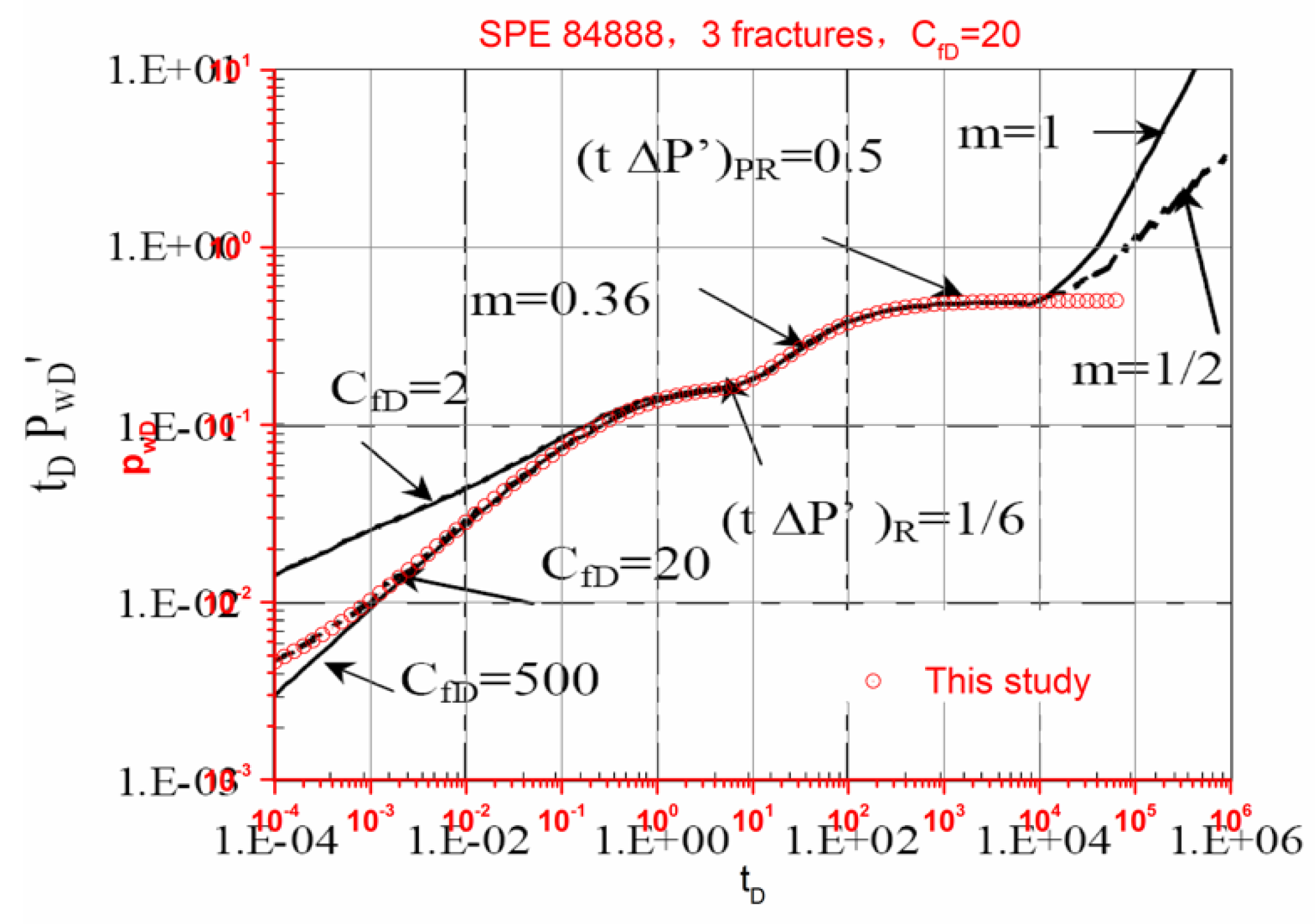
To the best of our knowledge, few publications have discussed the pressure behavior of multiple finite-conductivity fractures in CBM reservoirs. In order to validate the new model, we compared our solution with that reported by Zerar [19] for finite conductivity fracture in a homogeneous reservoir (f(s) = s). It is shown that our solutions excellently match with Zerar’s solutions before the boundary is felt (Figure 3).

3.2. Flow Characteristics Analysis

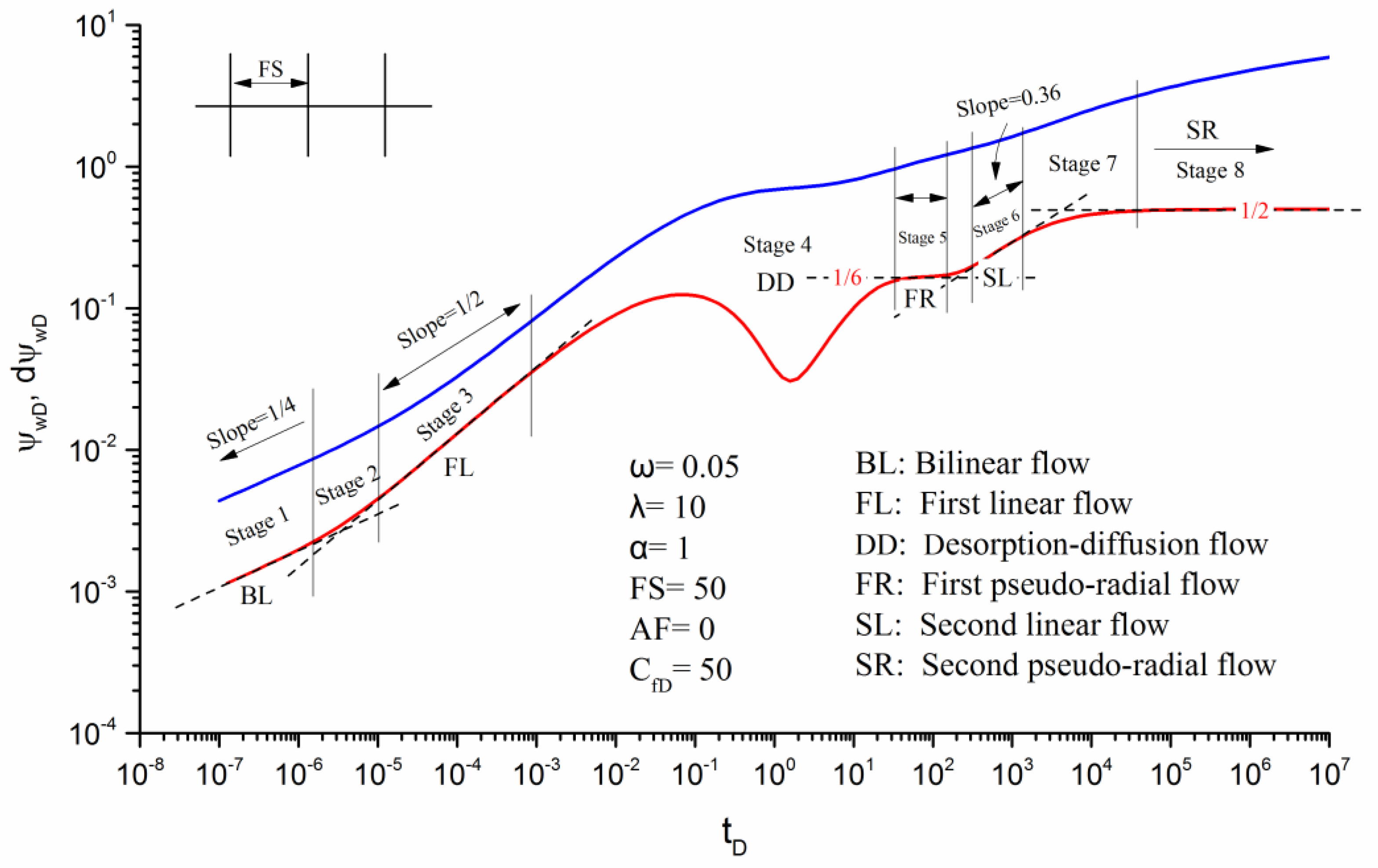
Figure 4 presents the transient pseudo-pressure response of a horizontal well with N (N = 3) fractures. The fractures are of equal length and distribute uniformly with equal fracture spacing.
As shown in Figure 4, we can divide the flow of fluid into eight stages in CBM reservoirs.
Stage 1: In this stage, the pseudo-pressure derivative curve (red line) has a straight line with a slope of 1/4, representing the bilinear flow period. This period can only be observed in low-moderate fracture conductivity.
Stage 2: A transition period occurs from the bilinear flow to the first linear flow.
Stage 3: The first linear flow period, which is characterized by a straight line with a slope of 1/2 on the pseudo-pressure derivative curve.
Stage 4: Because of the effect of desorption and diffusion mechanisms, a typical dip followed by the first linear flow on the pseudo-pressure derivative can be observed. This flow period can continue for a long time and is easy to be observed.
Stage 5: The first pseudo-radial flow period will be observed while the pseudo-pressure derivative curve shows a constant as 1/ (2N). In this period, fluids flow radially from the formation to each fracture individually under the condition that the fracture spacing is sufficiently large compared with the half-length of the fracture.
Stage 6: The second linear flow period, which is characterized by a straight line with a slope of 0.36 on the pseudo-pressure derivative curve, can be observed when the fracture interference is felt.
Stage 7: A transition period occurs from the second linear flow to the second pseudo-radial flow.
Stage 8: The second pseudo-radial flow period is distinguished by a horizontal line on the pseudo-pressure derivative curve, which shows a stable value of 0.5.
It should be noted that not all flow periods illustrated in Figure 4 exist for all horizontal wells with multiple fractures in coalbed methane reservoirs. It depends on the combinations of parameters, such as fracture conductivity, diffusion model, storability ratio, inter-porosity flow coefficient, adsorption index, fracture spacing, fracture asymmetry, non-planar angle, and wellbore storage. In the following section, the impacts of these parameters on transient pseudo-pressure responses will be analyzed.

3.3. Effects of Parameters on Transient Pseudo-Pressure Responses

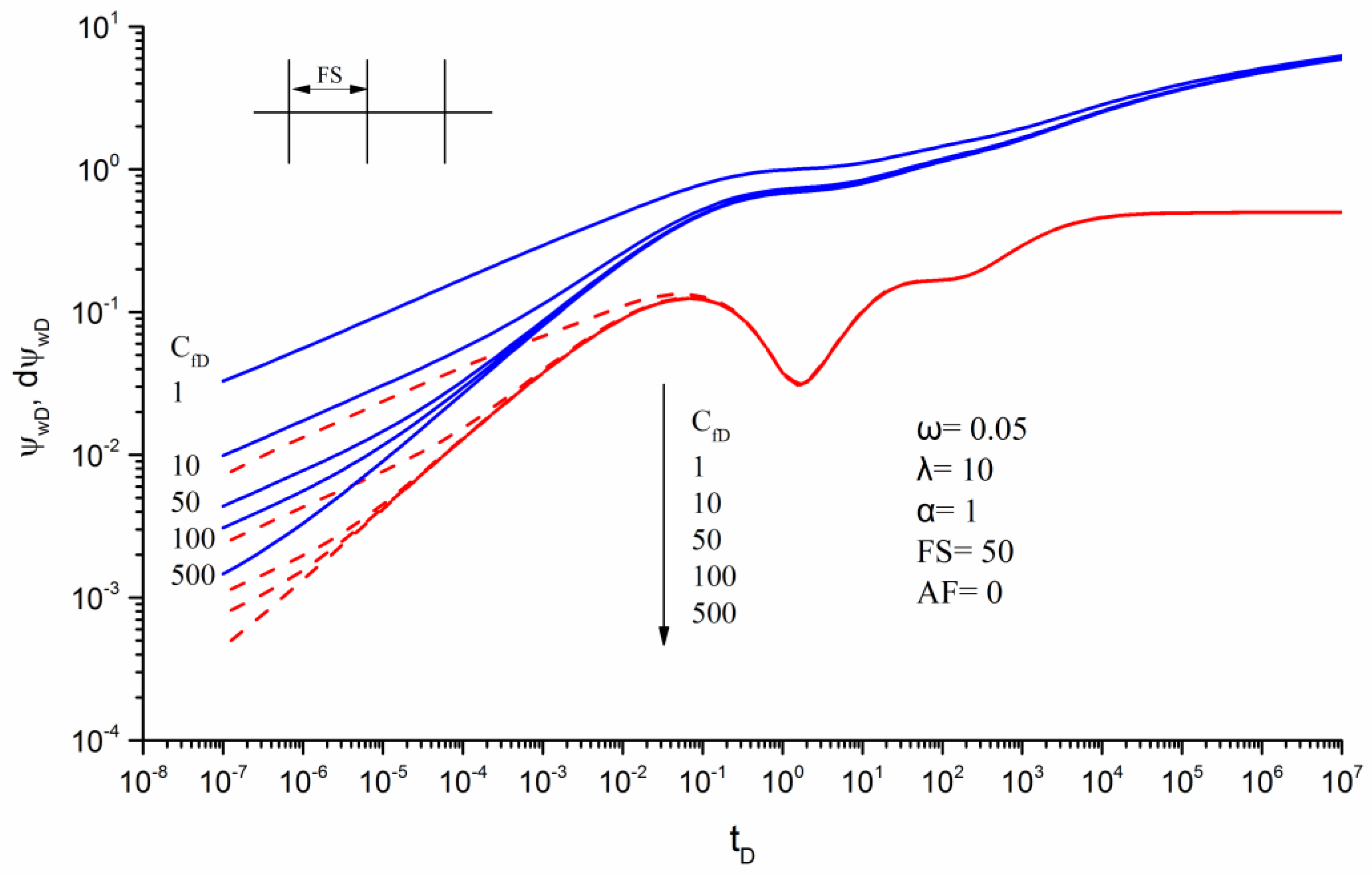
Fracture conductivity (CfD).Figure 5 presents the pseudo-pressure and pseudo-pressure derivative curves for different dimensionless fracture conductivities. As shown in Figure 5, the fracture conductivity has a major effect on the early pseudo-pressure responses. In the case of low fracture conductivity (CfD = 1), the bilinear flow can be identified clearly and the first linear flow can’t be observed. With the increase of the fracture conductivity, the duration of the bilinear flow decreases and the first linear flow gradually dominates the fluid flow in the CBM reservoir. At the moderate fracture conductivity (CfD = 10 ~ 50), both the bilinear flow and the first linear flow can be identified. When the fracture conductivity is greater than 100, the first linear flow can be recognized easily, whereas the bilinear flow will be absent.
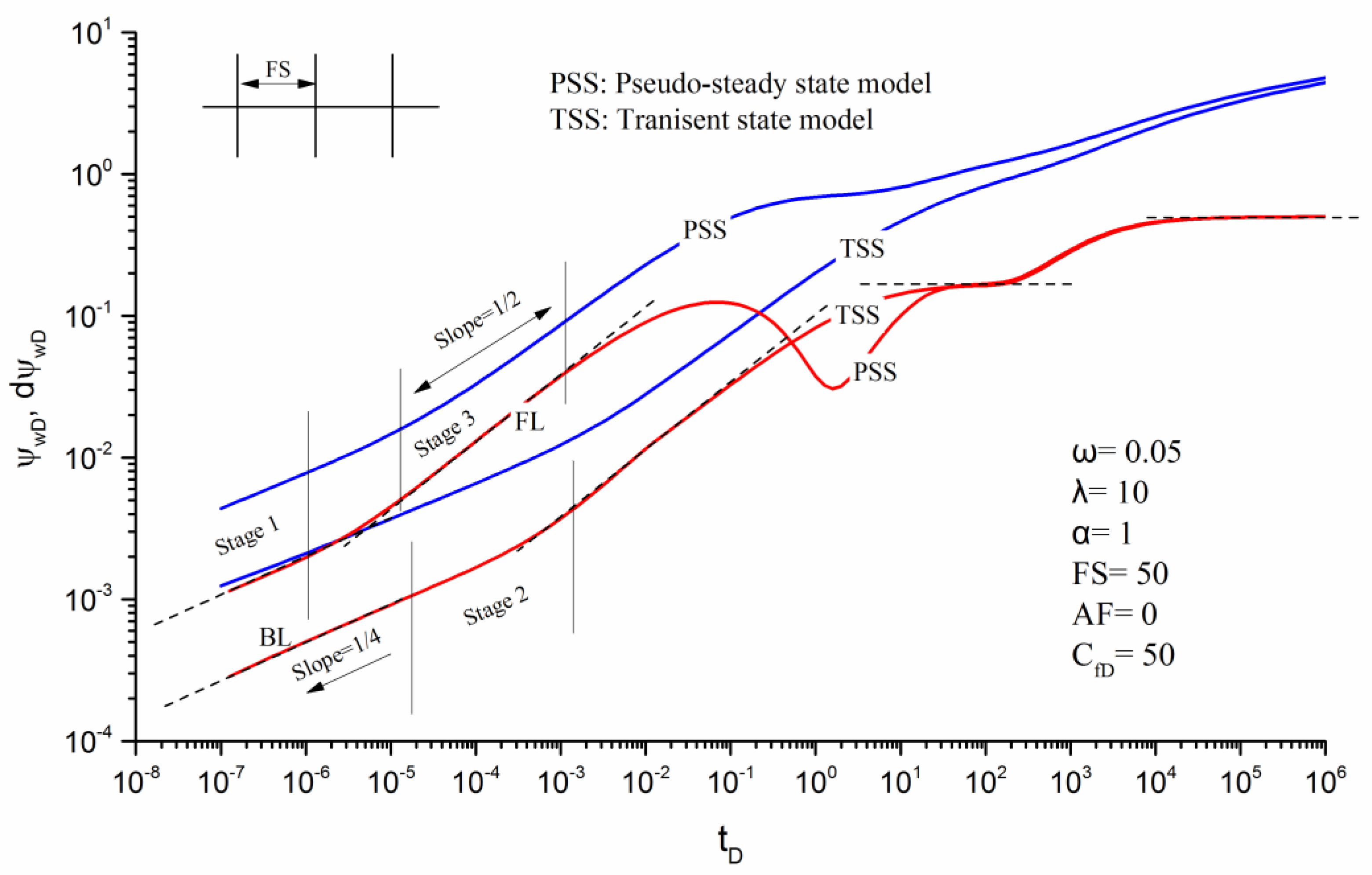
Transient state (TSS) diffusion and pseudo-steady state (PSS) diffusion.Figure 6 displays the typical pseudo-pressure curves of TSS and PSS models with other identical parameters.
As can be seen in Figure 6, the eight stages presented in the PSS model can also be observed in the TSS model. At a large dimensionless time (tD ≥ 102), both the TSS and PSS model have the same value on the curves of pseudo-pressure derivative. However, during the intermediate time (10−2tD ≤ 102), the shapes of the pseudo-pressure derivative curve exhibit huge differences. The characteristic dip on the pseudo-pressure derivative is no longer observed with the TSS model. In the early stages, the diffusion model mainly affects the end of both the bilinear flow and the first linear flow. It can be observed the end of bilinear flow and first linear flow for the PSS model occurs earlier than that of the TSS model. Meanwhile, we notice that in the early flow period (tD < 10−1), the values of pseudo-pressure and derivative for the PSS model are obviously bigger compared with the TSS model, indicating larger pressure depletions in the PSS model.
Storability ratio (ω).Figure 7 presents the influence of storability ratio ω on the transient pseudo-pressure responses with different fracture conductivities. The storability ratio has a significant effect on the early-stage pseudo-pressure responses.
Table 1 displays the pseudo-pressure and pseudo-pressure derivative data for different storability ratios, and it can be seen that in the early and middle flow periods (tD ≤ 102), the pseudo-pressure increases as ω reduces, which indicates that a small storability ratio leads to large pressure depletion. For example, when CfD = 1 and tD = 10−1, the pseudo-pressure ΨwD is 0.7861 for the case of ω = 0.05, while they are 0.6951 and 0.4948 for the ω = 0.1 and ω = 0.5, respectively. The storability ratio exerts influence on the flow stage of desorption-diffusion. As shown on the derivative curves, the dip is wider and deeper with the decrease in the storability ratio.
The influence of storability ratio depends on the fracture conductivity (Figure 7a–c). For low fracture conductivity (CfD = 1, Figure 7a), the storability ratio influences the bilinear flow period, while it affects the first linear flow period for high conductivity (CfD = 500, Figure 7c). For moderate fracture conductivity (CfD = 50, Figure 7b), both the bilinear and first linear flow periods will be affected.
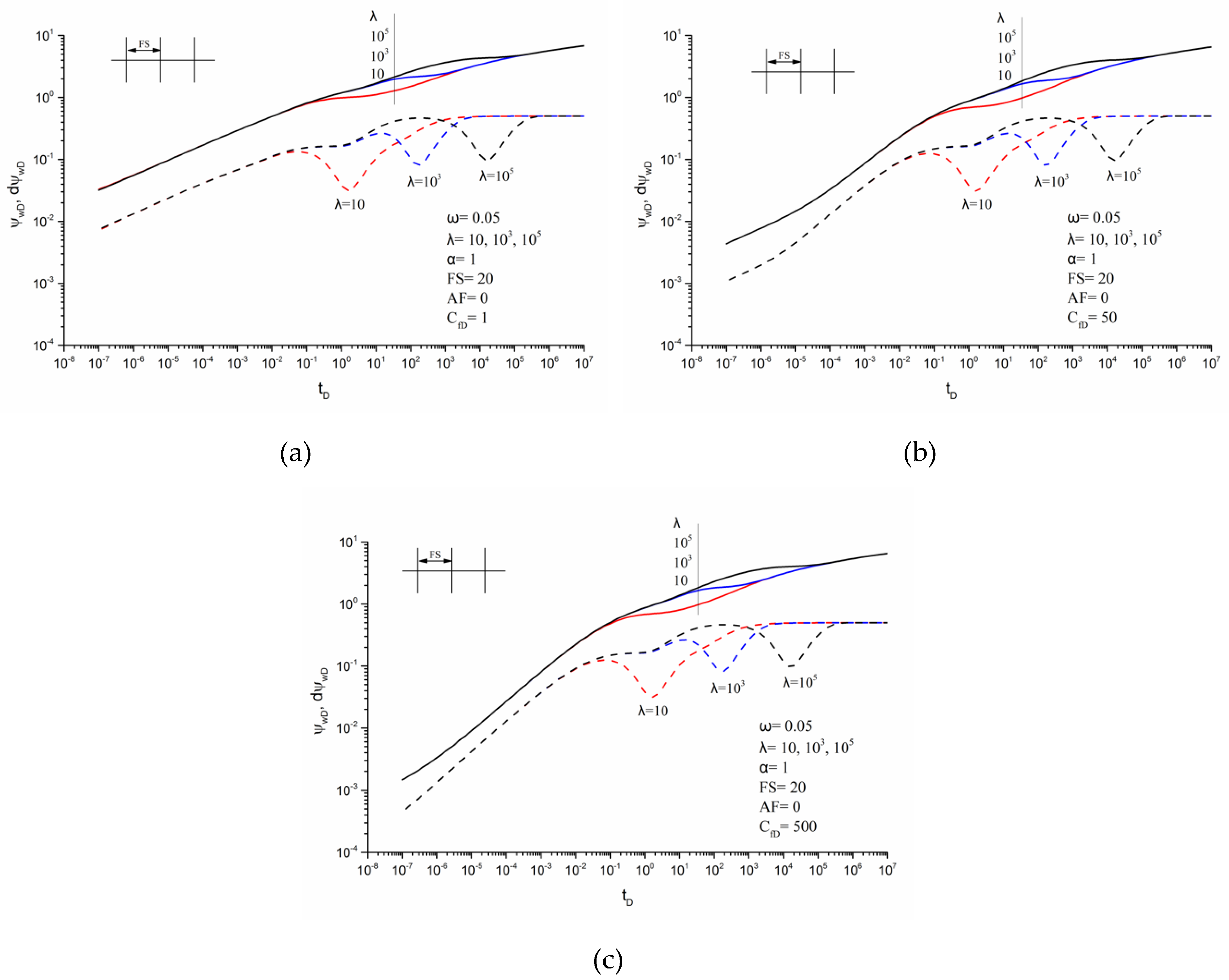
Inter-porosity flow coefficient (λ).Figure 8 illustrates the effect of inter-porosity flow coefficient λ on the transient pseudo-pressure responses. It indicates that the inter-porosity flow coefficient mainly affects stage 4, the desorption-diffusion flow period. As the inter-porosity flow coefficient increases, the dip of pseudo-pressure derivative curves moves towards the right. With a big inter-porosity flow coefficient (λ = 105), two segments of the second pseudo-radial flow separated by the desorption-diffusion flow can be observed on the derivative curves.
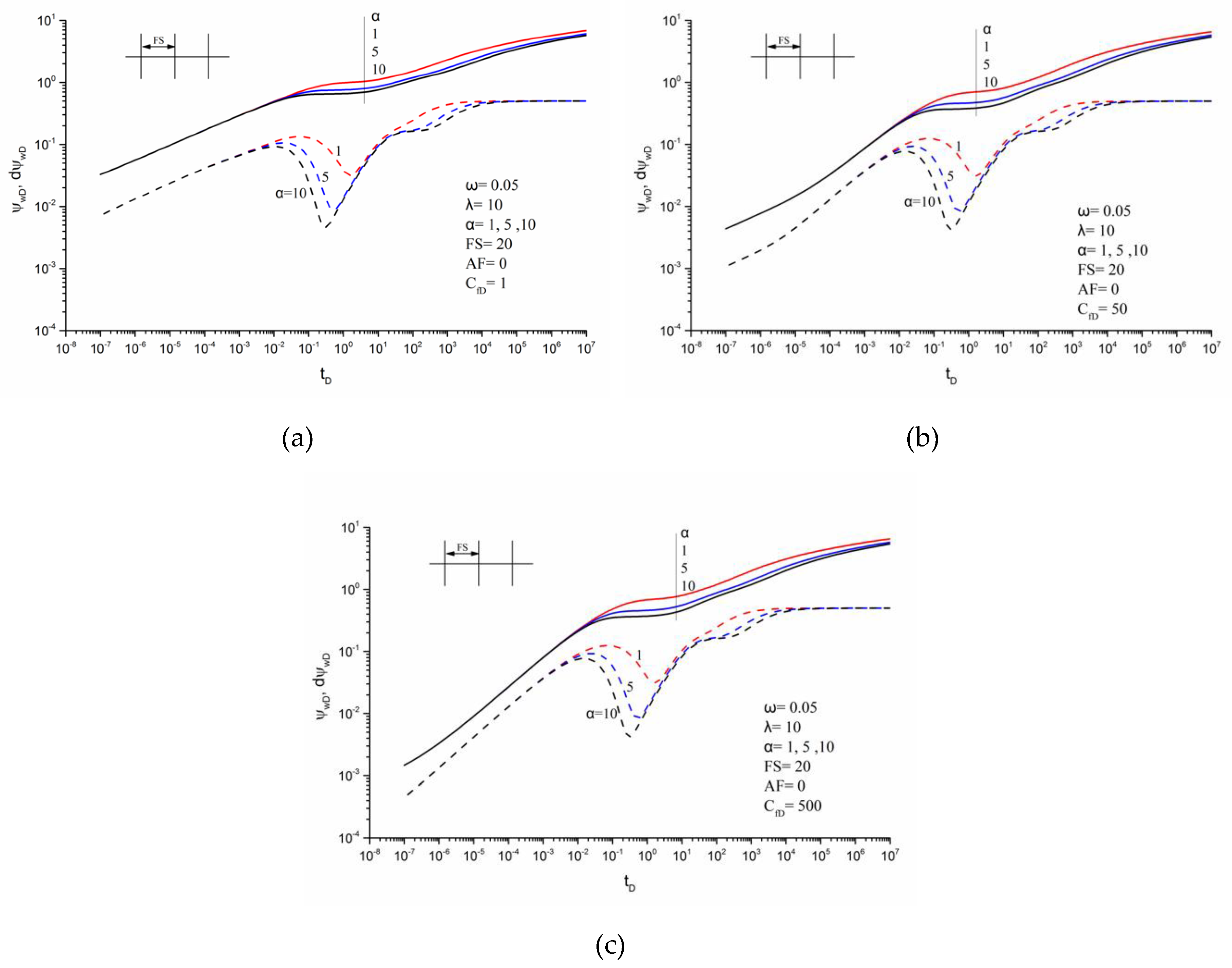
Adsorption index (α).Figure 9 demonstrates the impact of adsorption index α on the transient pseudo-pressure responses. It can be seen that the adsorption index mainly impacts the flow periods of stage 4, 5, 6, and 7.
Comparing Figure 9 with Figure 7 and Figure 8, the storability ratio, ω, mainly affects the magnitudes of dip on the pseudo-pressure derivative curve, while the inter-porosity flow coefficient, λ, mainly affects the occurring time of the desorption and diffusion. However, the adsorption index, α, exerts the influence on both the magnitude of dip and the occurring time of desorption and diffusion. In addition, the dips become deeper and wider with the increase of adsorption index. It should be noted that the effects of storability ratio and inter-porosity flow coefficient on the pseudo-pressure responses will gradually disappear after the desorption-diffusion flow period, while the impact of adsorption index will continue to exist in the subsequent flow periods.
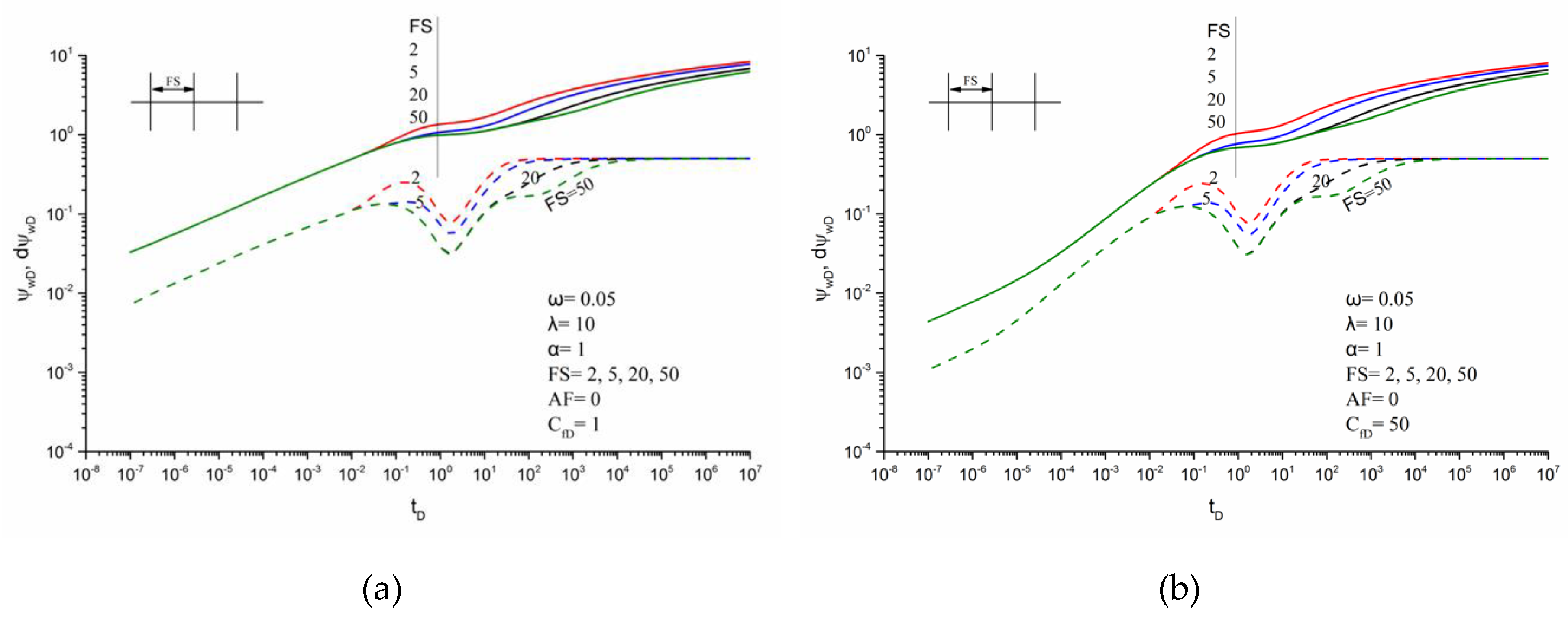
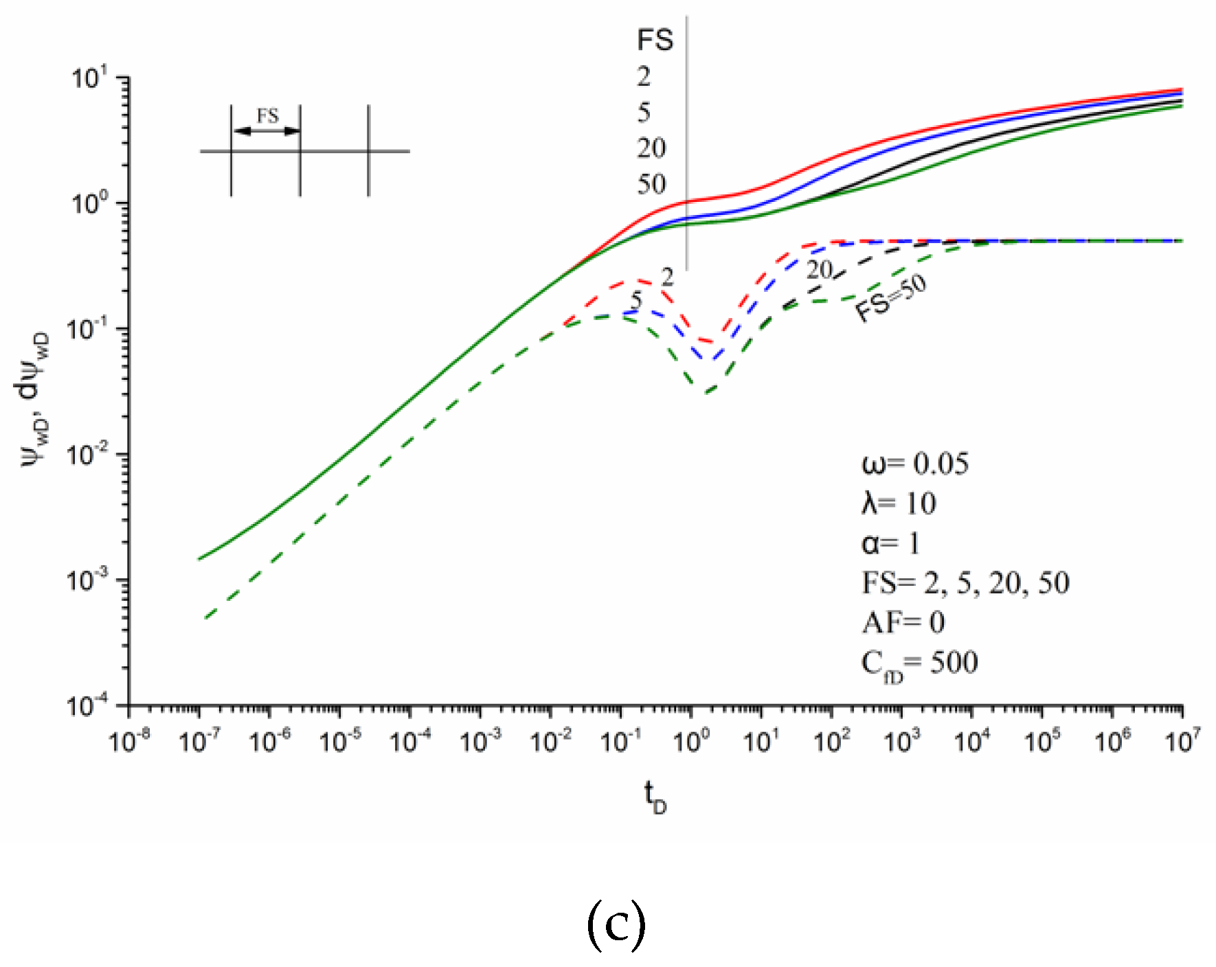
Fracture spacing (FS).Figure 10 presents the typical pseudo-pressure curves of different fracture spacing with low, moderate and high fracture conductivities. As the fracture spacing increases, the first pseudo-radial flow stage becomes longer, indicating weaker pressure interference between the fractures. As can be seen in Figure 10, the first pseudo-radial flow can be identified clearly when FS is equal to 50, while it may be masked when FS is less than 20. In practice, the dimensionless fracture spacing is usually less than 5, thus, the first pseudo-radial flow may not occur. Another phenomenon shown in Figure 10 is that the dip moves upward as FS reduces.
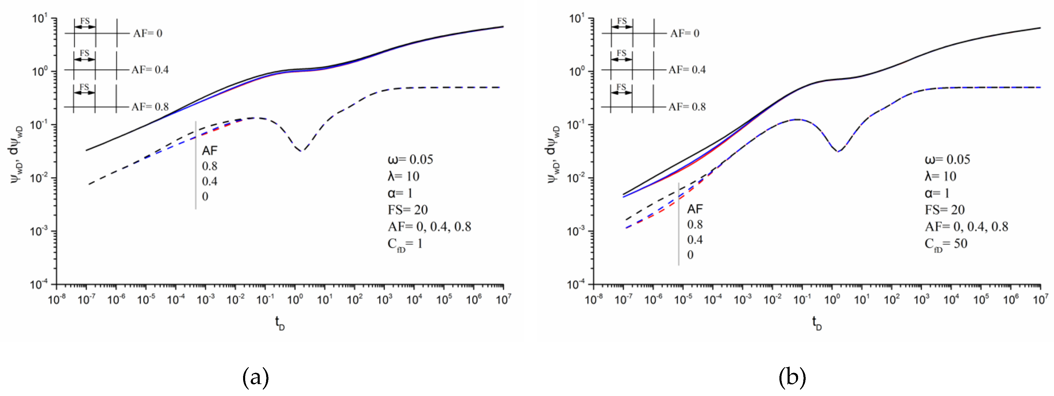
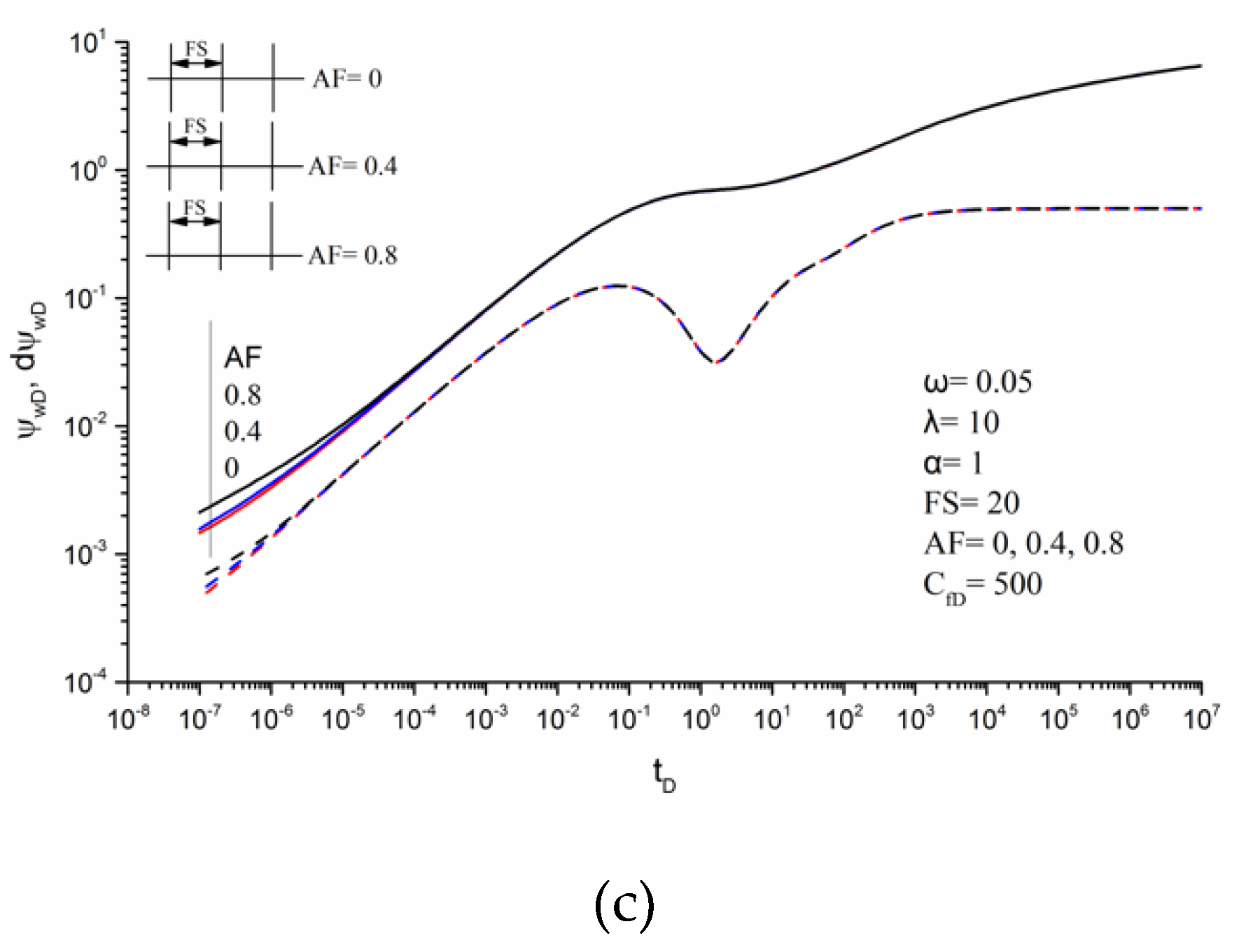
Asymmetry factor (AF).Figure 11 presents the impact of the asymmetry factor on the pseudo-pressure responses. We assume each fracture has an identical asymmetry factor, AF = 0, 0.4, and 0.8.
Observe that the asymmetry factor mainly influences the early flow periods. The fractures for different conductivities are parallel and coplanar without the wings interference, and the CBM production is mainly supplied by reservoirs far away from the well in the late flow period, the result being that the production performances of asymmetric fractures and symmetric fractures are approximate. For example, when CfD = 50 and tD = 103, the pseudo-pressures for the AF of 0, 0.4 and 0.8 are 2.0077, 2.0098, and 2.0166, respectively.
Under the condition of low fracture conductivity (Figure 11a), the bigger the AF is, the earlier the end of bilinear flow occurs. The pseudo-pressure derivative curve also exhibits a deviation from the one fourth slope line responding to the bilinear flow for moderate fracture conductivity (Figure 11b). When the dimensionless fracture conductivity is equal to 500, the first linear flow can also be identified with the impact of the asymmetry factor (Figure 11c).
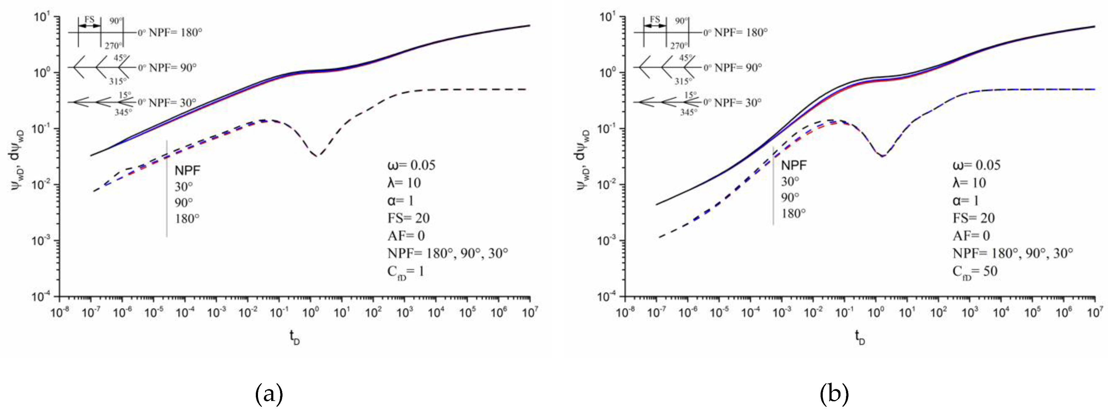
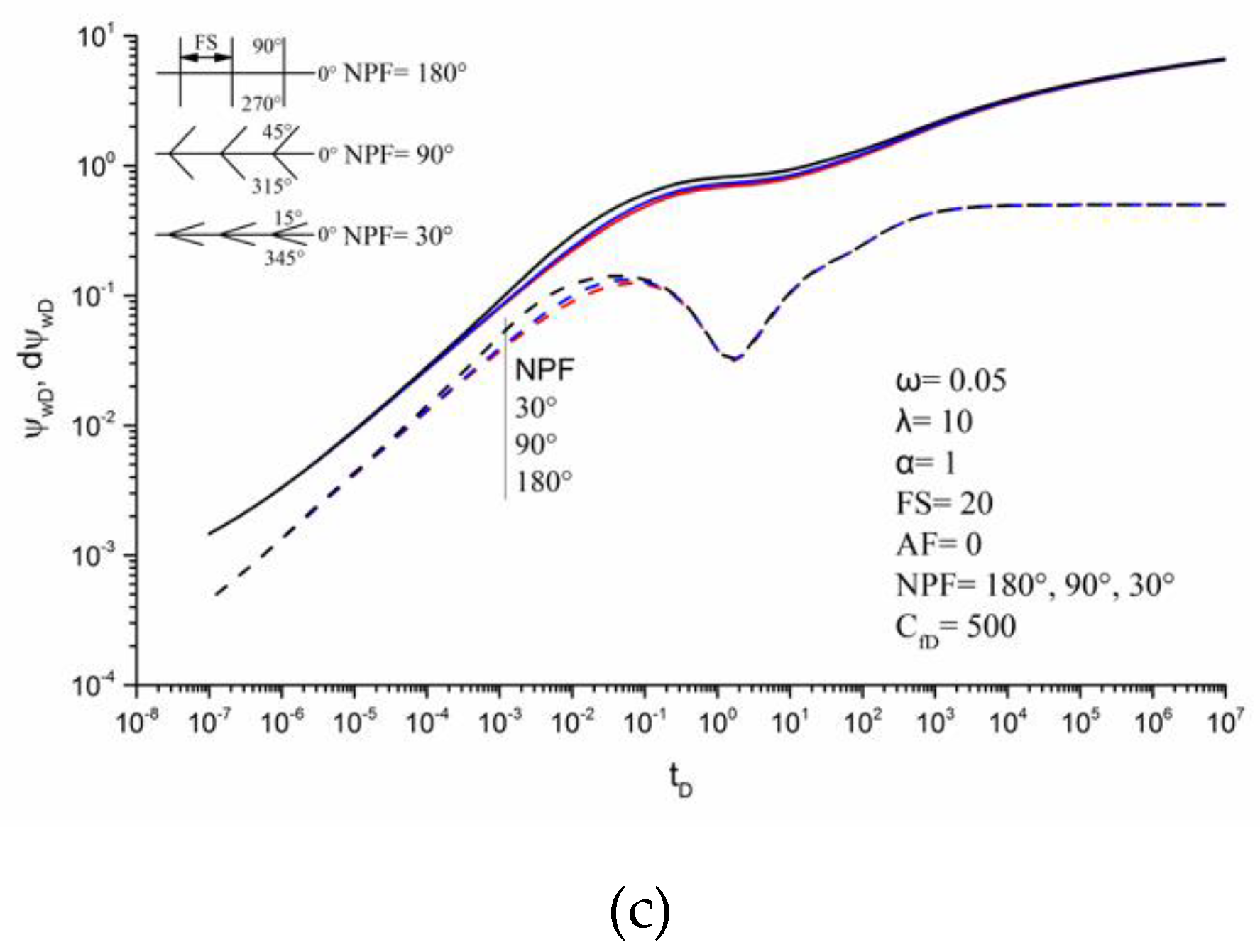
Non-planar angle (NPF).Figure 12 shows the effect of non-planar angle on the pseudo-pressure responses. In our study, the hydraulic fracture system of a horizontal well in coalbed methane reservoirs can be simulated by random combinations of fracture wing, which means that each group of hydraulic fractures can be composed of odd or even fracture wings with different angles or lengths.
For convenience, the non-planar angles between the two wings of each fracture are considered to be equal in this case. The values of NPF are set to be 30°, 90°, and 180°, respectively. Therefore, the case of NPF = 180° corresponds to the coplanar fracture in our study.
As shown in Figure 12, as the NPF decreases, the pressure interference between the two wings of each fracture reinforces, which eventually leads to a larger pressure drop. It should be noted that the pressure interference caused by the non-planar wings will continue to show a non-negligible effect on the late production response. Such as when CfD = 50 and tD = 103, the pseudo-pressures for the NPF of 30°, 90°, and 180° are 2.1443, 2.0515, and 2.0077, respectively. In the case of low fracture conductivity (Figure 12a), a hump caused by wings interference can be observed with a small NPF, such as NPF = 30°, which eventually shortens the duration of the bilinear flow. With the increase in fracture conductivity, the influence of non-planar angle on the pseudo-pressure curves is delayed. For fractures of intermediate and high conductivity (Figure 12b,c), the end of the first linear flow period occurs earlier with the decrease of NPF.
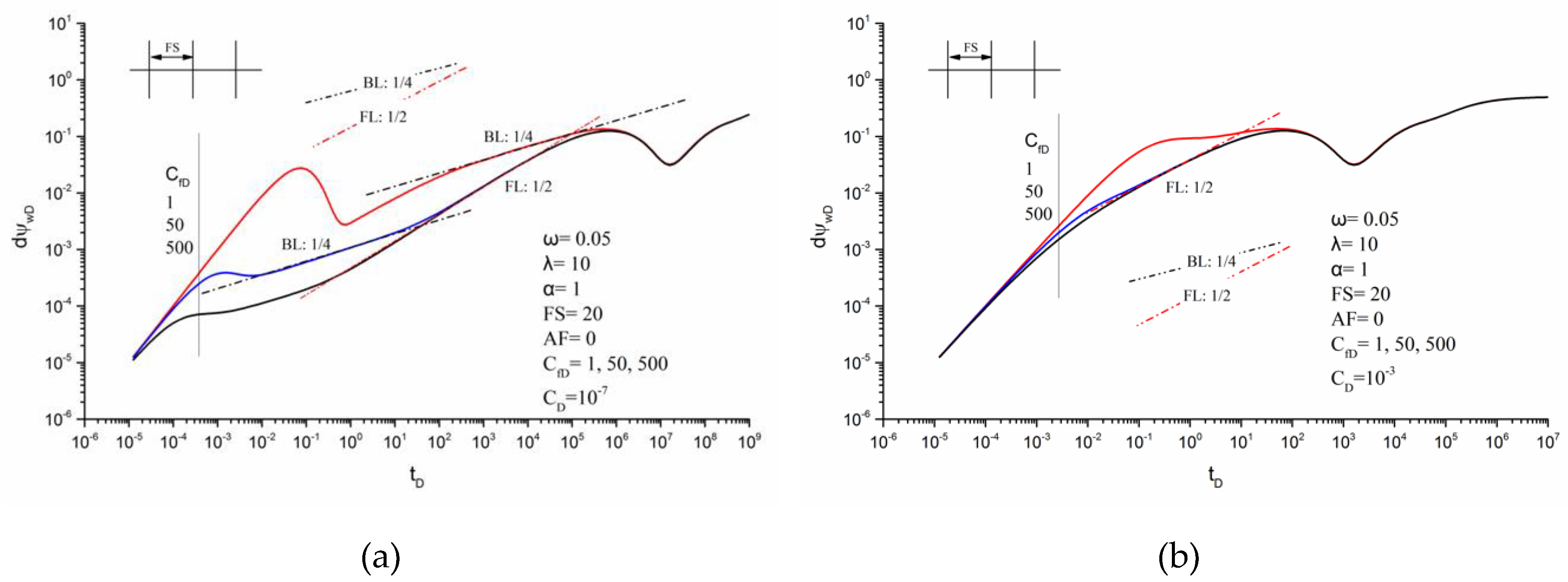
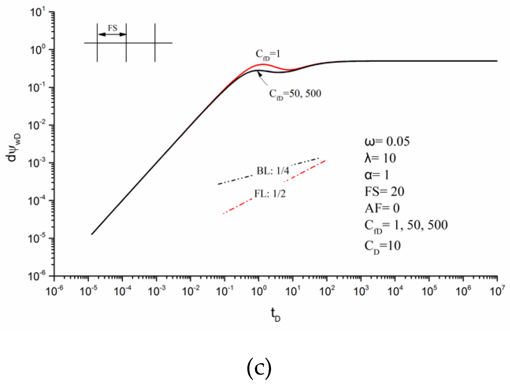
Wellbore storage (CD).Figure 13 shows the typical pseudo-pressure curves of a multi-fractured horizontal well with the consideration of wellbore storage CD. The CD is considered to be 10−7, 10−3, and 10, respectively.
The characteristics of early flow periods depend on the value of CD. With the increase of CD, the duration of the wellbore storage period increases, which is characterized by a straight line with a slope of one. For small value of CD, for example, CD = 10−7 (Figure 13a), the wellbore storage makes the occurrence of flow periods delay and all characteristic flow periods can be identified. However, for big values of CD, like CD = 10−3 (Figure 13b), the wellbore storage can lead to the absence of the early bilinear flow period. For large values of CD, (CD = 10, Figure 13c), the wellbore storage will dominate the fluid flow in the whole of the early period, resulting the absence of characteristic flow periods.

4. Conclusions

Based on our study, several important conclusions can be drawn.
(1) Based on a new fracture wing model, a semi-analytical model has been proposed to obtain the pseudo-pressure responses of horizontal wells with multiple fractures in coalbed methane reservoirs. The effects of fracture conductivity, diffusion model, storability ratio, inter-porosity flow coefficient, adsorption index, fracture spacing, fracture asymmetry, non-planar angle, and wellbore storage on the transient pseudo-pressure responses have been investigated.
(2) Six characteristic flow periods can be identified: bilinear flow, first linear flow, desorption-diffusion flow, first pseudo-radial flow, second linear flow, and second pseudo-radial flow for a multi-fractured horizontal well in coalbed methane reservoirs.
(3) The fracture conductivity exhibits a major effect on the early pseudo-pressure responses. In the case of low fracture conductivity, the bilinear flow can be recognized clearly, and the first linear flow can’t be observed. With an increase in the fracture conductivity, the duration of the bilinear flow decreases and the first linear flow gradually dominates the fluid flow in the coalbed methane reservoir. At moderate fracture conductivity, both the bilinear flow period and the first linear flow period can be identified. When the dimensionless fracture conductivity is greater than 100, the first linear flow can be recognized easily, whereas the bilinear flow will not occur.
(4) Results show that several parameters affect the pseudo-pressure responses in coalbed methane reservoirs. As the parameter value increases, both the storability ratio and the inter-porosity flow coefficient make the lowest point in the dip move in the top right orientation; the adsorption index leads to the move of the lowest point towards the bottom left corner and the fracture spacing makes the lowest point drop vertically. Sensitivity analysis also indicates that the asymmetry factor mainly impacts the bilinear flow periods. A small non-planar angle will cause strong pressure interference between the wings, eventually making the end of the bilinear flow or the first linear flow occur earlier. Small wellbore storage merely delays the occurrence of flow periods, while large wellbore storage may conceal the bilinear flow and the first linear flow period.

Author Contributions

Conceptualization, Q.T. and W.L.; Data curation, Y.C.; Formal analysis, Y.C.; Investigation, Q.T. and Y.C.; Methodology, Q.T. and W.L.; Resources, W.L.; Supervision, W.L. and P.L.; Validation, P.L. and B.N.; Visualization, Pengcheng Liu; Writing – original draft, Q.T., Y.C. and W.L.; Writing – review & editing, Q.T., Y.C. and W.L. All authors have read and agreed to the published version of the manuscript.

Funding

This research was funded by the National Natural Science Foundation of China (Grant No. 51674227) and the Fundamental Research Funds for the Central Universities.

Acknowledgments

This work was supported by the National Natural Science Foundation of China (Grant No. 51674227) and the Fundamental Research Funds for the Central Universities.

Conflicts of Interest

The authors declare no conflict of interest.

Nomenclature

Dimensionless Variables: Real Domain
CfDdimensionless fracture conductivity
tDdimensionless time
CDdimensionless wellbore storage coefficient
ψwDdimensionless well bottom pseudo pressure
ψDdimensionless pseudo pressure
Ddimensionless pseudo pressure derivative
ψfDdimensionless pseudo fracture pressure
AFfracture asymmetry factor
FSdimensionless fracture spacing
λinter-porosity flow coefficient
ωstorability ratio
αadsorption index
Dimensionless Variables: Laplace Domain
stime variable in Laplace domain, dimensionless
ψ ¯ D dimensionless pseudo pressure ψD in Laplace domain
ψ ¯ w D bottom pressure ψwD in Laplace domain
ψ ¯ f D dimensionless pseudo fracture pressure ψfD in Laplace domain
q ¯ f D dimensionless fracture rate qfD in Laplace domain
Field Variables
cttotal compressibility, 1/psi
keffective permeability, mD
pffracture pressure, psi
piinitial formation pressure, psi
qfrate of per unit fracture length from formation, MMscf/d
Qtotal rate of all fracture wings in the wellbore, MMscf/d
µfluid viscosity, cp
hformation thickness, ft
φporosity, fraction
tinitial time variable, h
hformation thickness, ft
Ttemperature, R
Zgas compressibility factor, fraction
Ziinitial gas compressibility factor, fraction
Bgiinitial volume factor, fraction
Lffracture wing length, ft
wfwidth of the fracture, ft
Special Functions
ffracture property
Ddimensionless
ggas property
scstandard condition
iinitial condition
wwellbore property

Appendix A. Derivation of Fracture-Wing Model in a Coalbed Methane Reservoir

For the fracture wing shown in Figure 2, the fluid flow in the wing is one-dimension in the Cartesian coordinate. The length of the wing is Lf with height h and width wf, and the fracture permeability is kf.
The dimensionless fracture pseudo-pressure is given as
ψ f D = 2 π k h Q B g i μ i ( ψ i ψ )
where Q is the total flow rate of all fracture wings in the wellbore.
Dimensionless distance
x D = x / L r e f ,   y D = y / L r e f ,   L f D = L f / L r e f
Dimensionless fracture wing conductivity, CfD, and the dimensionless flow rate, qfD, are defined as
C f D = k f w f k L r e f
q f D = p f p i Z i Z 1 B g i q f L f Q
Note that fracture conductivity can be different from each other in our model.
The rate of the fracture wing flow can be expressed as
q f w D = p f p i Z i Z 1 B g i 1 Q 0 L f q f d x = p f p i Z i Z 1 B g i q f w Q
We can get the flow equation in the fracture by the method of Cinco-Ley et al. [10]
x ( p f μ Z p f x ) + μ k f p f μ Z ( q f w f h ) = 0 ,   0 x L f
The initial and boundary conditions can be written as
p f ( x , t = 0 ) = p i ,   0 x L f
( k f h w f μ ) · ( p f x ) x = 0 = q f w
( p f x ) x = L f = 0
The gas pseudo-pressure can be written as
ψ ( p ) = μ i Z i p i p 0 p f p f μ Z d p f
Taking Equation (A10) into Equation (A6) through Equation (A9) yields
2 ψ x 2 + μ k f μ i Z i p i p f μ Z ( q f w f h ) = 0
ψ = ψ i ,   t = 0
( ψ x ) x = 0 = μ i p f p i Z i Z ( 1 k f w f ) 1 h q f w
( ψ x ) x = L f = 0
We can get the dimensionless equations by dimensionless transformation. The flow equation in the fracture can be described as
2 ψ f D x D 2 2 π C f D q f D = 0
The initial condition is
ψ f D ( x D , t D = 0 ) = 0 ,   0 x D L f D
Boundary conditions can be rearranged as
( ψ f D x D ) x D = 0 = 2 π C f D q f w D
And
( ψ f D x D ) x D = L f D = 0
Integrating Equation (A15) from 0 to xD with respect to xD
ψ f D ( x D ) x D ψ f D ( x D = 0 ) x D = 2 π C f D 0 x D q f D ( u ) d u
Substituting Equation (A17) into Equation (A19) yields
ψ f D ( x D ) x D = 2 π C f D 0 x D q f D ( u ) d u 2 π C f D q f w D
Integrating Equation (A20) from 0 to xD with respect to xD
ψ f D ( x D ) ψ f D ( 0 ) = 2 π C f D 0 x D 0 v q f D ( u ) d u d v 2 π C f D q f w D x D
In the wellbore
ψ w D = ψ f D ( 0 )
Rearranging Equation (A21) yields
ψ w D ψ f D ( x D ) = 2 π C f D ( q f w D x D 0 x D 0 v q f D ( u ) d u d v )

References

  1. Gentzis, T. Review of the hydrocarbon potential of the Steele Shale and Niobrara Formation in Wyoming, USA: A major unconventional resource play? Int. J. Coal Geol. 2016, 166, 118–127. [Google Scholar] [CrossRef]
  2. Adiya, Z.I.S.G.; Dupont, V.; Mahmud, T. Steam reforming of shale gas in a packed bed reactor with and without chemical looping using nickel based oxygen carrier. Int. J. Hydrog. Energy 2018, 43, 6904–6917. [Google Scholar] [CrossRef]
  3. Dong, G.J.; Chen, P. A comparative experiment investigate of strength parameters for Longmaxi shale at the macro- and mesoscales. Int. J. Hydrog. Energy 2017, 42, 20082–20091. [Google Scholar] [CrossRef]
  4. Yao, Y.B.; Liu, D.M.; Tang, D.Z.; Tang, S.H.; Che, Y.; Huang, W.H. Preliminary evaluation of the coalbed methane production potential and its geological controls in the Weibei Coalfield, Southeastern Ordos Basin, China. Int. J. Coal Geol 2009, 78, 1–15. [Google Scholar] [CrossRef]
  5. Lin, F.; Sheng, P.; Li, C.Y. Fracture parameter optimization of fractured horizontal well of coal bed gas reservoir. Zhongzhou Coal 2016, 2, 126–128. [Google Scholar]
  6. Zhou, J.J. Development and utilization status and technical progress of coalbed methane in China. Petrochem. Ind. Appl. 2017, 36, 1–4. [Google Scholar]
  7. Wang, G.Y.; Feng, Q.T.; Li, P. Research on mining technology of coalbed gas through staged fracturing horizontal well along the roof of coal seam. J. Shanxi Datong Univ. 2013, 29, 68–70. [Google Scholar]
  8. Ji, Y.; He, B.S.; Liu, S.J.; Cao, S.F.; Zhang, B.H. Improvement technology of CBM horizontal well fracturing in Qinshui Basin. Coal Sci. Technol. 2016, 44, 173–178. [Google Scholar]
  9. Wang, J.; Yao, T.Q. Study on CBM horizontal well sectional fracturing parameters optimization in Zhaozhuang Minefield. Coal Geol. China 2017, 29, 35–39. [Google Scholar]
  10. Cinco-Ley, H.; Samaniego, V.F.; Dominguez, A.N. Transient pressure behavior for a well with a finite-conductivity vertical fracture. SPE J. 1978, 18, 253–264. [Google Scholar]
  11. Luo, W.J.; Tang, C.F. Pressure-transient analysis of multiwing fractures connected to a vertical wellbore. SPE J. 2015, 20, 360–367. [Google Scholar] [CrossRef]
  12. Tian, Q.; Liu, P.C.; Jiao, Y.W.; Bie, A.F.; Xia, J.; Li, B.Z.; Liu, Y. Pressure transient analysis of non-planar asymmetric fractures connected to vertical wellbores in hydrocarbon reservoirs. Int. J. Hydrog. Energy 2017, 42, 18146–18155. [Google Scholar] [CrossRef]
  13. Liu, Q.G.; Xu, Y.J.; Peng, X.; Liu, Y.C.; Qi, S.Z. Pressure transient analysis for multi-wing fractured wells in dual-permeability hydrocarbon reservoirs. J. Petrol. Sci. Eng. 2019, 180, 278–288. [Google Scholar] [CrossRef]
  14. Larsen, L.; Hegre, T.M. Pressure-transient behavior of horizontal wells with finite-conductivity vertical fractures. In Proceedings of the International Arctic Technology Conference, Anchorage, AK, USA, 29–31 May 1991. Paper No. SPE-22076. [Google Scholar] [CrossRef]
  15. Guo, G.L.; Evans, R.D. A systematic methodology for production modelling of naturally fractured reservoirs intersected by horizontal wells. In Proceedings of the SPE/CIM/CANMET International Conference on Recent Advances in Horizontal Well Applications, Calgary, AB, Canada, 20–23 March 1994. Paper No. PETSOC-HWC-94-40. [Google Scholar] [CrossRef]
  16. Horne, R.N.; Temeng, K.O. Relative productivities and pressure transient modeling of horizontal wells with multiple fractures. In Proceedings of the Middle East Oil Show, Bahrain, 11–14 March 1995. Paper No. SPE-29891. [Google Scholar] [CrossRef]
  17. Chen, C.C.; Rajagopal, R. A multiply-fractured horizontal well in a rectangular drainage region. SPE J. 1997, 2, 455–465. [Google Scholar] [CrossRef]
  18. Wan, J.; Aziz, K. Semi-analytical well model of horizontal wells with multiple hydraulic fractures. SPE J. 2002, 7, 437–445. [Google Scholar] [CrossRef]
  19. Zerzar, A.; Bettam, Y. Interpretation of multiple hydraulically fractured horizontal wells in closed systems. In Proceedings of the Canadian International Petroleum Conference, Calgary, AB, Canada, 8–10 June 2004. Paper No. PETSOC-2004-027. [Google Scholar] [CrossRef]
  20. Al-Kobaisi, M.; Ozkan, E.; Kazemi, H. A hybrid numerical-analytical model of finite-conductivity vertical fractures intercepted by a horizontal well. In Proceedings of the SPE International Petroleum Conference in Mexico, Puebla Pue., Mexico, 7–9 November 2004. Paper No. SPE-92040. [Google Scholar] [CrossRef]
  21. Stalgorova, E.; Mattar, L. Practical analytical model to simulate production of horizontal wells with branch fractures. In Proceedings of the SPE Canadian Unconventional Resources Conference, Calgary, AB, Canada, 30 October–1 November 2012. Paper No. SPE-162515. [Google Scholar] [CrossRef]
  22. Al-Rbeawi, S.J.H.; Djebbar, T. Transient pressure analysis of a horizontal well with multiple inclined hydraulic fractures using type-curve matching. In Proceedings of the SPE International Symposium and Exhibition on Formation Damage Control, Lafayette, LA, USA, 15–17 February 2012. Paper No. SPE-149902. [Google Scholar] [CrossRef]
  23. Wang, H.; Ran, Q.Q.; Liao, X.W. Pressure transient responses study on the hydraulic volume fracturing vertical well in stress-sensitive tight hydrocarbon reservoirs. Int. J. Hydrog. Energy 2017, 42, 18343–18349. [Google Scholar] [CrossRef]
  24. Yuan, B.; Zheng, D.; Moghanloo, R.G.; Wang, K. A novel integrated workflow for evaluation, optimization, and production predication in shale plays. Int. J. Coal Geol. 2017, 180, 18–28. [Google Scholar] [CrossRef]
  25. Xing, G.Q.; Wang, M.X.; Wu, S.H.; Li, H.; Dong, J.Y.; Zhao, W.Q. Pseudo-steady-state parameters for a well penetrated by a fracture with an azimuth angle in an anisotropic reservoir. Energies 2019, 12, 2449. [Google Scholar] [CrossRef] [Green Version]
  26. Wang, M.X.; Xing, G.Q.; Fan, Z.F.; Zhao, W.Q.; Lun, Z.; Heng, S. A novel model incorporating geomechanics for a horizontal well in a naturally fractured reservoir. Energies 2018, 11, 2584. [Google Scholar] [CrossRef]
  27. Xing, G.Q.; Wu, S.H.; Wang, J.H.; Wang, M.X.; Wang, B.H.; Cao, J.J. Pressure transient performance for a horizontal well intercepted by multiple reorientation fractures in a tight reservoir. Energies 2019, 12, 4232. [Google Scholar] [CrossRef] [Green Version]
  28. Venart, J.E.S.; Prasad, R.C.; Wang, G. Knudsen-effect errors with transient line-source measurement in fluids. Int. J. Thermophys. 1987, 8, 39–46. [Google Scholar] [CrossRef]
  29. Alata, M.; Al-Nimr, M.A.; Naji, M. Transient behavior of a thermoelectric device under the hyperbolic heat conduction model. Int. J. Thermophys. 2003, 24, 1753–1768. [Google Scholar] [CrossRef]
  30. Khadrawi, A.F.; Othman, A.; Al-Nimr, M.A. Transient free convection fluid flow in a vertical microchannel as described by the hyperbolic heat conduction model. Int. J. Thermophys. 2005, 26, 905–918. [Google Scholar] [CrossRef]
  31. Minea, A.A.; Buonomo, B.; Burggraf, J.; Ercole, D.; Karpaiya, K.R.; Pasqua, A.D.; Sekrani, G.; Steffens, J.; Tibaut, J.; Wichmann, N.; et al. NanoRound: A benchmark study on the numerical approach in nanofluids’ simulation. Int. Commun. Heat Mass. 2019, 108, 104292. [Google Scholar] [CrossRef]
  32. Sung, W.; Ertekin, T.; Schwerer, F.C. The development, testing, and application of a comprehensive coal seam degasification model. In Proceedings of the SPE Unconventional Gas Technology Symposium, Louisville, KY, USA, 18–21 May 1986. Paper No. SPE-15247. [Google Scholar] [CrossRef]
  33. Ertekin, T.; Sung, W. Pressure transient analysis of coal seams in the presence of multi-mechanistic flow and sorption phenomena. In Proceedings of the SPE Gas Technology Symposium, Dallas, TX, USA, 7–9 June 1989. Paper No. SPE-19102. [Google Scholar] [CrossRef]
  34. Anbarci, K.; Ertekin, T. A comprehensive study of pressure transient analysis with sorption phenomena for single-phase gas flow in coal seams. In Proceedings of the SPE Annual Technical Conference and Exhibition, New Orleans, LA, USA, 23–26 September 1990. Paper No. SPE-20568. [Google Scholar] [CrossRef]
  35. Anbarci, K.; Ertekin, T. A simplified approach for in-situ characterization of desorption properties of coal seams. In Proceedings of the Low Permeability Reservoirs Symposium, Denver, CO, USA, 15–17 April 1991. Paper No. SPE-21808. [Google Scholar] [CrossRef]
  36. Anbarci, K.; Ertekin, T. Pressure transient behavior of fractured wells in coalbed reservoirs. In Proceedings of the SPE Annual Technical Conference and Exhibition, Washington, DC, USA, 4–7 October 1992. Paper No. SPE-24703. [Google Scholar] [CrossRef]
  37. Guo, X.; Du, Z.M.; Li, S.L. Computer modeling and simulation of coalbed methane reservoir. In Proceedings of the SPE Eastern Regional Meeting, Pittsburgh, PA, USA, 6–10 September 2003. Paper No. SPE-84815. [Google Scholar] [CrossRef]
  38. Clarkson, C.R.; Jordan, C.L.; Ilk, D.; Blasingame, T.A. Production data analysis of fractured and horizontal CBM wells. In Proceedings of the SPE Eastern Regional Meeting, Charleston, WV, USA, 23–25 September 2009. Paper No. SPE-125929. [Google Scholar] [CrossRef]
  39. Aminian, K.; Ameri, S. Predicting production performance of CBM reservoirs. J. Nat. Gas Sci. Eng. 2009, 1, 25–30. [Google Scholar] [CrossRef]
  40. Nie, R.S.; Meng, Y.F.; Guo, J.C.; Jia, Y.L. Modeling transient flow behavior of a horizontal well in a coal seam. Int. J. Coal Geol. 2012, 92, 54–68. [Google Scholar] [CrossRef]
  41. Wang, L.; Wang, X.D.; Li, J.Q.; Wang, J.H. Simulation of pressure transient behavior for asymmetrically finite-conductivity fractured wells in coal reservoirs. Transp. Porous Med. 2013, 97, 353–372. [Google Scholar] [CrossRef]
  42. Zhang, L.H.; Kou, Z.H.; Wang, H.T.; Zhao, Y.L.; Dejam, M.; Guo, J.J.; Du, J. Performance analysis for a model of a multi-wing hydraulically fractured vertical well in a coalbed methane gas reservoir. J. Petrol. Sci. Eng. 2018, 166, 104–120. [Google Scholar] [CrossRef]
  43. Chen, X.X.; Wang, L.; Xue, L. A gaseous compound of hydrogen and carbon production performance model in coalbed reservoir with horizontal fractures. Int. J. Hydrog. Energy 2019, 44, 5262–5269. [Google Scholar] [CrossRef]
  44. Stehfest, H. Numerical inversion of Laplace transforms. Commun. ACM 1970, 13, 47–49. [Google Scholar] [CrossRef]
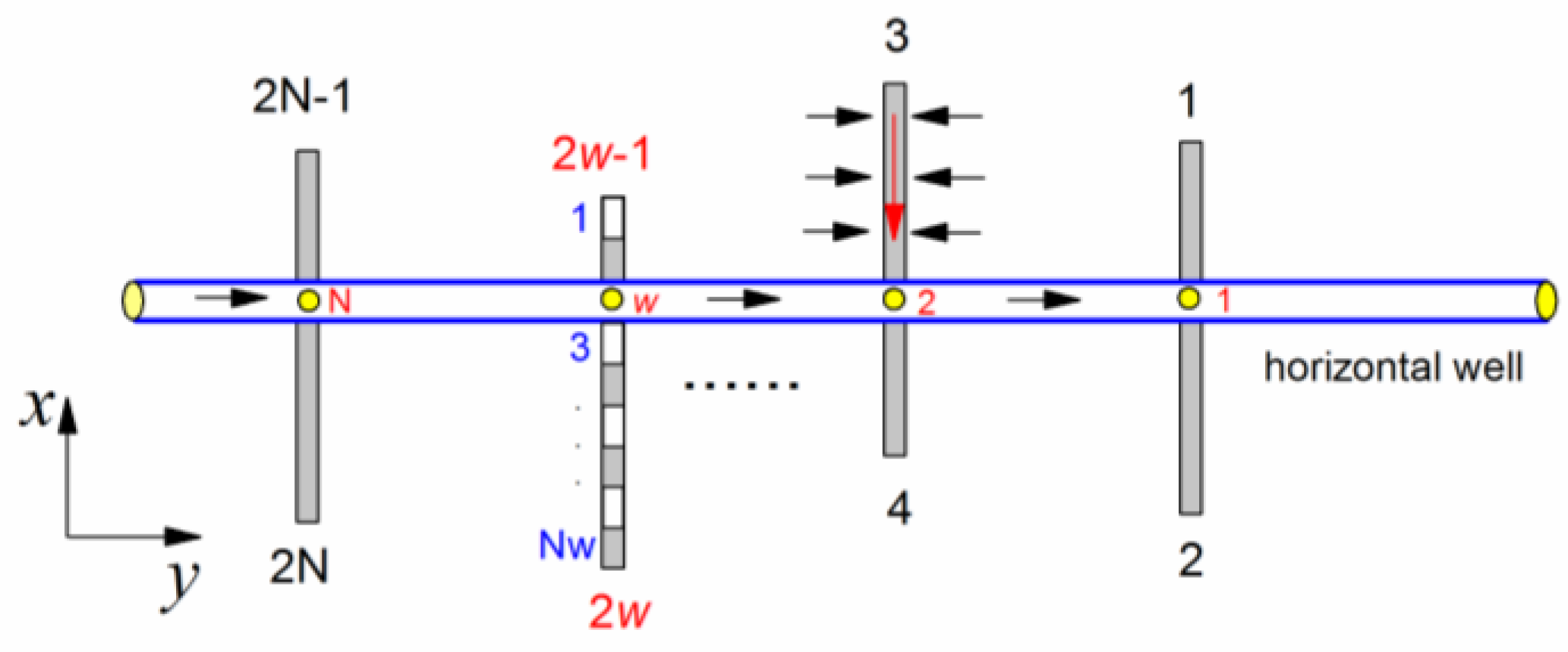
Figure 1. Schematic of multiple finite-conductivity fractures along a horizontal well.
Energies 13 01498 g001
Figure 2. Schematic of fluid flow in a wing.
Energies 13 01498 g002
Figure 3. Comparison of our solution for a multi-fractured horizontal well (red circles) with the solution of Zerar (SPE 84888).
Energies 13 01498 g003
Figure 4. The typical pseudo-pressure curves for a multi-fractured horizontal well in a coalbed methane (CBM) reservoir.
Energies 13 01498 g004
Figure 5. The pseudo-pressure responses for a multi-fractured horizontal well with different fracture conductivities.
Energies 13 01498 g005
Figure 6. Comparison of the typical pseudo-pressure curves for a multi-fractured horizontal well between pseudo-steady state (PSS) and transient state (TSS) models.
Energies 13 01498 g006
Figure 7. The typical pseudo-pressure curves of a multi-fractured horizontal well with different storability ratios. (a) Low conductivity; (b) intermediate conductivity; (c) high conductivity.
Energies 13 01498 g007
Figure 8. The typical pseudo-pressure curves of a multi-fractured horizontal well with different inter-porosity flow coefficient. (a) Low conductivity; (b) intermediate conductivity; (c) high conductivity.
Energies 13 01498 g008
Figure 9. The typical pseudo-pressure curves of a multi-fractured horizontal well with different adsorption index. (a) Low conductivity; (b) intermediate conductivity; (c) high conductivity.
Energies 13 01498 g009
Figure 10. The typical pseudo-pressure curves of a multi-fractured horizontal well with different fracture spacing. (a) low conductivity; (b) intermediate conductivity; (c) high conductivity.
Energies 13 01498 g010aEnergies 13 01498 g010b
Figure 11. The typical pseudo-pressure curves of a multi-fractured horizontal well with different asymmetry factor. (a) low conductivity; (b) intermediate conductivity; (c) high conductivity.
Energies 13 01498 g011aEnergies 13 01498 g011b
Figure 12. The typical pseudo-pressure curves of a multi-fractured horizontal well with different non-planar angle. (a) Low conductivity; (b) intermediate conductivity; (c) high conductivity.
Energies 13 01498 g012aEnergies 13 01498 g012b
Figure 13. The effect of wellbore storage on the pseudo-pressure responses. (a) Low wellbore storage; (b) intermediate wellbore storage; (c) high wellbore storage.
Energies 13 01498 g013aEnergies 13 01498 g013b
Table 1. The pseudo-pressure and pseudo-pressure derivative data for different storability ratio.
CfD = 1ω = 0.05ω = 0.1ω = 0.5
tDΨwDwDΨwDwDΨwDwD
10−60.05590.01330.04740.01110.03290.0072
10−50.09710.02370.08210.01980.05590.0133
10−40.17010.04110.14390.03500.09710.0237
10−30.29330.06770.24970.05860.17020.0411
10−20.49400.11020.42290.09530.29340.0677
10−10.78610.12870.69510.13410.49480.1112
1000.98900.03850.96060.07560.79820.1419
1011.11130.10471.11090.10461.09990.1268
1021.50940.24531.50900.24551.50560.2474
1032.31400.43822.31400.43832.31380.4386
1043.40630.49303.40630.49303.40630.4930
1054.55130.49934.55130.49934.55130.4993
1065.70200.50005.70200.50005.70200.5000
CfD = 50ω = 0.05ω = 0.1ω = 0.5
tDΨwDwDΨwDwDΨwDwD
10−60.00780.00200.00650.00160.00440.0011
10−50.01460.00450.01190.00340.00780.0020
10−40.03300.01310.02530.00940.01460.0045
10−30.08670.03760.06430.02760.03300.0131
10−20.22860.09020.17250.07180.08670.0376
10−10.49110.12310.40520.12420.22920.0911
1000.68940.03800.66110.07460.50210.1357
1010.80920.10290.80880.10280.79720.1253
1021.20460.24491.20410.24511.20070.2470
1032.00770.43752.00770.43762.00750.4379
1043.09920.49293.09920.49293.09920.4929
1054.24410.49934.24410.49934.24410.4993
1065.39480.50005.39480.50005.39480.5000
CfD = 500ω = 0.05ω = 0.1ω = 0.5
tDΨwDwDΨwDwDΨwDwD
10−60.00330.00130.00250.00100.00150.0005
10−50.00900.00420.00660.00300.00330.0013
10−40.02680.01290.01930.00920.00900.0042
10−30.08010.03730.05780.02740.02680.0129
10−20.22110.08980.16540.07140.08010.0374
10−10.48290.12290.39710.12390.22170.0906
1000.68100.03800.65270.07450.49380.1355
1010.80080.10290.80030.10280.78880.1253
1021.19600.24491.19560.24511.19220.2470
1031.99920.43751.99910.43751.99890.4379
1043.09060.49293.09060.49293.09060.4929
1054.23550.49934.23550.49934.23550.4993
1065.38620.50005.38620.50005.38620.5000