Article

Analysis of the Converter Synchronizing Method for the Contribution of Battery Energy Storage Systems to Inertia Emulation

by
Andrés Peña Asensio
1,
Francisco Gonzalez-Longatt
2,
Santiago Arnaltes
1,* and
Jose Luis Rodríguez-Amenedo
1
1
Departamento de Ingeniería, Eléctrica Universidad Carlos III de Madrid, 28911 Leganés, Spain
2
Institutt for Elektro, IT og Kybernetikk,Universitetet I Sørøst-Norge, 3918 Porsgrunn, Norway
*
Author to whom correspondence should be addressed.
Energies 2020, 13(6), 1478; https://doi.org/10.3390/en13061478
Submission received: 27 January 2020 / Revised: 6 March 2020 / Accepted: 13 March 2020 / Published: 20 March 2020
(This article belongs to the Special Issue Energy Storage for Grid Integration of Renewable Energy)

Abstract

:
This paper presents a comprehensive analysis of the effect of the converter synchronizing methods on the contribution that Battery Energy Storage Systems (BESSs) can provide for the support of the inertial response of a power system. Solutions based on phase-locked loop (PLL) synchronization and virtual synchronous machine (VSM) synchronization without PLL are described and then compared by using time-domain simulations for an isolated microgrid (MG) case study. The simulation results showed that inertial response can be provided both with and without the use of a PLL. However, the behavior in the first moments of the inertia response differed. For the PLL-based solutions, the transient response was dominated by the low-level current controllers, which imposed fast under-damped oscillations, while the VSM systems presented a slower response resulting in a higher amount of energy exchanged and therefore a greater contribution to the support of the system inertial response. Moreover, it was demonstrated that PLL-based solutions with and without derivative components presented similar behavior, which significantly simplified the implementation of the PLL-based inertia emulation solutions. Finally, results showed that the contribution of the BESS using VSM solutions was limited by the effect of the VSM-emulated inertia parameters on the system stability, which reduced the emulated inertia margin compared to the PLL-based solutions.

1.Introduction

In traditional electrical power systems, power generation relies on the use of synchronous generators (SGs) directly connected to the power network. Due to the rotating nature of the SG, the rotor inherently stores kinetic energy (KE) in it. Furthermore, in the event of a sudden power imbalance, the SG has the natural property of adjusting its power injection to the network by taking KE from its rotor. Therefore, the so-called “inertial response” (IR) of the SGs has a positive impact on the frequency stability of the power system.
On the other hand, Battery Energy Storage Systems (BESSs) are connected to the power network by using a power conditioning system (PCS). In contrast with SGs, the PCS has no inherent IR per se. If BESSs are going to compensate for the variability of renewable generation to substitute traditional sources, they must be able to support power imbalances. Thus, the frequency response must be enabled in the PCS by adding a specific frequency-sensible control loop that allows for a synthetic emulation of the IR [1]. The mechanisms used to mimic the inertial frequency response of SGs in PCS-based technologies are called “inertia emulation” (IE) [2,3] in this paper.
The power converter technologies commonly used for PCSs in BESS applications have been the conventional two- and three-level voltage source converters (VSCs), and more recently, the modular multilevel converter (MMC). Among PCSs, uses of VSCs are widespread due to their excellent relation between controllability and power ratings [4]. Several control techniques of grid-connected VSCs (or simply, VSCs) have been proposed in the scientific literature for injecting power into an AC system. Among them, vector current control (VCC) and power angle control (PAC) are the two that have been most investigated [5]. One of the main features of those control mechanisms on VSCs is the possibility of controlling their active and reactive power independently. However, to perform this control, the VSC AC voltage and the network voltage must be synchronized [4].
This paper presents the effects of different VSC synchronizing methods on IE provision from BESSs in an isolated microgrid (MG) application. The paper focuses on two synchronizing methods: (i) phase-locked loop (PLL)-based and (ii) power-balance-based.
In almost all grid-connected VSCs, a PLL is used to obtain an accurate synchronization with the grid [6,7]. Since the PLLs provide a measured frequency signal, it can be used to detect frequency disturbances related to power imbalances. When a frequency variation is measured, the active power output of the BESS can be varied accordingly, thus supporting the system frequency by providing a fast active power injection similar to the one provided by SGs. On the other hand, the power-balance-based synchronizing method uses a relationship between the VSC active power and frequency, in a similar way to SGs, as in the so-called virtual synchronous machine (VSM) control systems [8]. By introducing this relation between active power and frequency, BESSs inherently provide an IR equivalent to that of SGs [9].
Therefore, IE through VSCs can be implemented by using both PLL and VSM synchronizing methods. This paper discusses the effect of the converter synchronizing method on the resulting emulated IR from BESSs in an isolated MG application.
To understand the effect of the synchronizing method on the emulation of IR, the methodology employed in the study involved categorizing available solutions for the emulation of IR from BESS according to the required synchronizing method. Then, the analytical model to produce each of the solutions for each synchronizing method category were produced to understand how the synchronizing methods can be tuned to provide a specific IR such that they can be compared using equivalent settings. Then, the IRs provided by the solutions were compared with the use of indicators related to the effect of the IR on the system stability: the rate of change of frequency (RoCoF) and the frequency nadir. Using this methodology, it was possible to establish a relationship between the synchronizing method and the inertial response effect on the system.
Section 2 shows a concise overview and classification of existing synchronizing method and control systems used for IE through BESSs. Section 3 explains the implementation of different IE control systems, including both PLL- and VSM-based solutions. The implemented solutions were modeled to provide equivalent IR characteristics. Finally, Section 4 is dedicated to presenting the effects of these implementations through a discrete-time-domain simulation of an isolated MG system.
The main contributions of this paper can be summarized as follows:
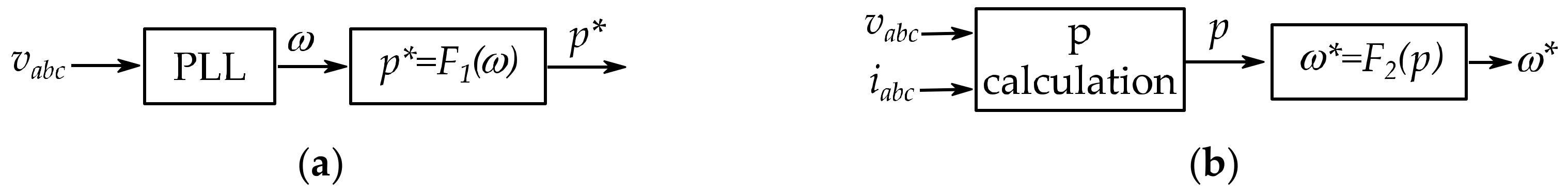
  • Review and categorization of IE control systems according to their synchronizing method: The review of IE control systems presented in Section 2 presents a classification in two groups according to whether they use a PLL or a power-balance-based synchronization.
  • Discrete-time implementations of both PLL- and VSM-based IE control systems with equivalent parameters: To study the effect of the synchronization method on the resulting emulated inertial response, representative solutions of both PLL-based and power-balance-based IE control systems were modeled with equivalent emulated inertia characteristics, as shown in Section 3.
  • Analysis of the IE response provided by solutions both with and without the use of a PLL: The results presented in Section 4 show that, despite the equivalent settings, the effect of PLL-based and power-balance-based IE solutions was different in the first moments following a power imbalance.

2. Inertia Emulation Using BESSs: A Concise Review

This section presents a concise review of the control systems used to provide IE in VSC-based BESSs, according to their synchronization method.
BESSs have been proposed as a method for solving different problems related to intermittent generation, such as mitigation voltage issues [10] or the reduction of electricity costs through the load shifting of Photovoltaic (PV) power [11]. This paper addresses the problems caused by the reduction in the total system inertia due to the increasing penetration of power electronic converter (PEC)-interfacing generation systems. Specifically, this paper considers the improvement in the system stability that can be achieved thanks to the contribution of energy from ESSs. Inertia support through ESSs is a growing issue for traditional power systems operators like the United Kingdom National Grid [12]. The benefits of using energy storage for inertia support were also highlighted in the European Massive InteGRATion of Power Electronic Devices (MIGRATE) project [13].
In this paper, the term IE is used to represent control techniques that replicate the IR of SGs. Existing IE solutions used in BESS applications are reviewed and categorized according to their synchronizing method (see Figure 1): (i) solutions based on PLLs for grid synchronization, and (ii) power-balance-based synchronizing method as SGs [14], also known as VSMs [15].
PLL-based IE solutions use a ω-controller that regulates their active power reference output as a function of the variations on the measured frequency:
p * = F 1 ω ,
where p* represents an active power reference given to the BESS VSC and ω represents the angular speed of the voltage signals (vabc) measured by a PLL. In this study, it was assumed that ω (in pu) = f (in pu); as a consequence, the PLL output signal represents the electrical frequency (f).
The power-balance-based synchronizing method or VSM (used as a synonym from here onward) uses a p-controller (p represents active power, which is not be confused with a proportional controller) that varies its frequency (angular speed, ω*) depending on the measured active power (p) in a similar way to SGs. The basic action of control is described as:
ω * = F 2 p ,
where ω* represents the frequency reference used to orientate the VSC AC voltage and p is the active power measured at the BESS output. The active power is calculated from the voltages (vabc) and current signals (iabc).

2.1.Solutions Based on PLL Synchronization

In a traditional SG-dominated power system, the system frequency changes to compensate for variations in generation and demand. Therefore, the system frequency can be used as an indicator of power imbalances.
Considering the relation between the power balance and frequency, a possible implementation of IE is to vary the BESS active power generation according to frequency variations [16]. Providing an automatic variation of the BESS active power reference as a function of the variation of frequency is usually referred to as virtual inertia (VI) [2].
A VI controller combines the effect of a “derivative control” component and a “proportional control” or “droop” component [17]. The derivative term is designed to emulate the SG inertial response, while the proportional term emulates the SG governor “droop” action. This difference is used by some authors to distinguish between the proportional and derivative terms for different applications [18]. In this study, these control actions were combined and were named virtual inertia from here onward. It should be noted that the “droop” action in VI systems is implemented oppositely than in an SG governor. While in the SG governing the speed reference is varied depending on the controller actuation [19], for VI, this is emulated oppositely by measuring the frequency (angular speed, ω) and varying the power output (actuation) [2]. Both implementations are compared graphically in Figure 2.
VI systems depend on a frequency signal (f) to produce an emulated inertial response, which is usually the case only when there is synchronous generation in the system, and it has already been decelerated (or accelerated). Therefore, these systems are reported to have little effect on the initial rate of change of frequency (RoCoF) rate but a significant influence on the frequency nadir (fmin) [20]. On the other hand, they are known to have adverse effects on the small-signal stability of weakly interconnected systems [21]. For the same reason, they require the presence of an external voltage with physical inertia and are therefore not suitable for islanded operation [14].

2.2.Virtual Synchronous Machines

One crucial characteristic of SGs is the inherent property of naturally responding to the system frequency variations without the use of any control mechanism of external frequency measurements. Instead, as stated earlier, they regulate their internal frequency by utilizing variations of active power. The BESS control system can be adapted to respond similarly.
For a VSC-interfaced BESS, if the demand in the system increases, so does the power generation from the VSC due to the electrical connection between them. In such a situation, an SG would decelerate due to the release of kinetic energy. A BESS can emulate this behavior by reducing its control system internal frequency. The dynamics of the VSC control system while trying to restore the initial power output will lead to an effective delivery (or reception) of energy from the converter to the grid, equivalent to that of a real SG inertial response. This principle, which is inherent to an SG swing equation, is used by the VSM control systems to emulate the inertial response of SGs.
The first VSMs were based on the digital implementation of complete SG numerical models on the converter control system. This is the case of the VIrtual Synchronous MAchine (VISMA), which implements a seventh-order model [22] Furthermore, this is the basis of the synchronverter concept, which implements a reduced second-order model [23,24]. VISMA and synchronverter implementations have the advantage of using well-known parameters from SG operation for the control tuning. The use of higher-order models, while increasing the control complexity, has not been reported to provide enhanced properties [14].
However, for IE purposes, it is not necessary to emulate the complete behavior of an SG. As stated earlier, the inertial response comes from the SG intrinsic swing equation. A more specific implementation of the SG swing equation can be found in the “power synchronization control” [25], which avoids the use of a numerical model of the machine.
Moreover, D’Arco and Suul [8] demonstrates that the power/frequency (p/f) droop control that it is commonly used in Uninterruptible Power Supply (UPS) applications to share the load between converters [26,27] also implements an analogous swing equation where the inertia is represented by the power measurement filter time constant. Further development of this concept can be found in the VSM with zero inertia (VSMH0) concept [28], which modifies the filter of a droop control such that the system can keep the VSM synchronization capabilities without providing inertia. Therefore, although p/f droop control systems were proposed before the extension of the VSM concept [29], in this work, they were considered as implementations of the VSM concept.
By emulating the behavior of the SG mechanical system, the same relations between active power and frequency can be obtained for a conventional SG and a VSM-controlled VSC. However, in the case of the VSC, there is no real rotating system. Therefore, the power and energy required by the resulting swing equation must be available in the system to ensure stability. This is why VSM solutions are usually associated with BESSs [30].

3.Synchronizing Method and IE: Implementation

This section presents the modeling and implementation aspects of converter synchronizing methods and IE controllers used in BESSs for isolated MG applications. The effect of the synchronizing mechanism is assessed by considering IE implementations based on both PLL and VSM synchronizing methods, as defined in Section 1.
First, to study the effect of the PLL, irrespective of the IE control implementation, the BESS active power is controlled to be a constant value through a PLL-based voltage-oriented control (VOC) system. VOC allows for the regulation of the VSC power through conventional PI compensators. VOC is described in more detail in the following subsection.
For PLL-based solutions, the VOC system is used as the underlying control system that regulates the active power reference provided by the VI controller. The VI implementation with only the proportional component is referred to as “VI-P,” while the implementation with both proportional and derivative components is referred to as “VI-PD.” Finally, a VSM solution based on the synchronverter concept is presented, focusing on the relationship between active power and frequency.

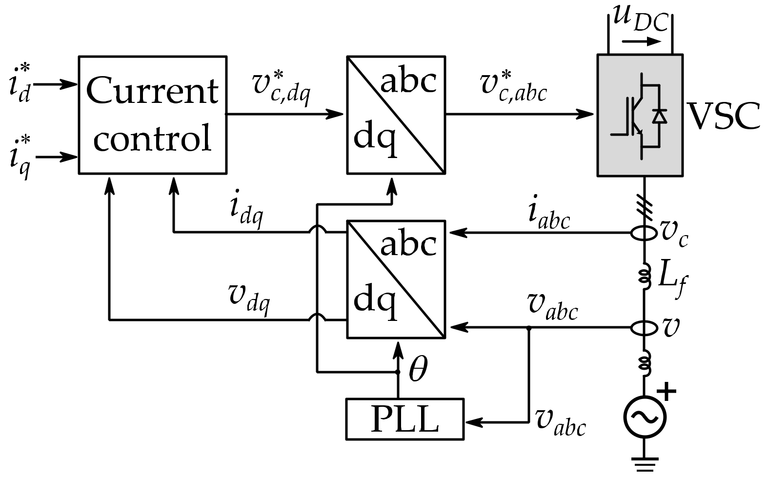
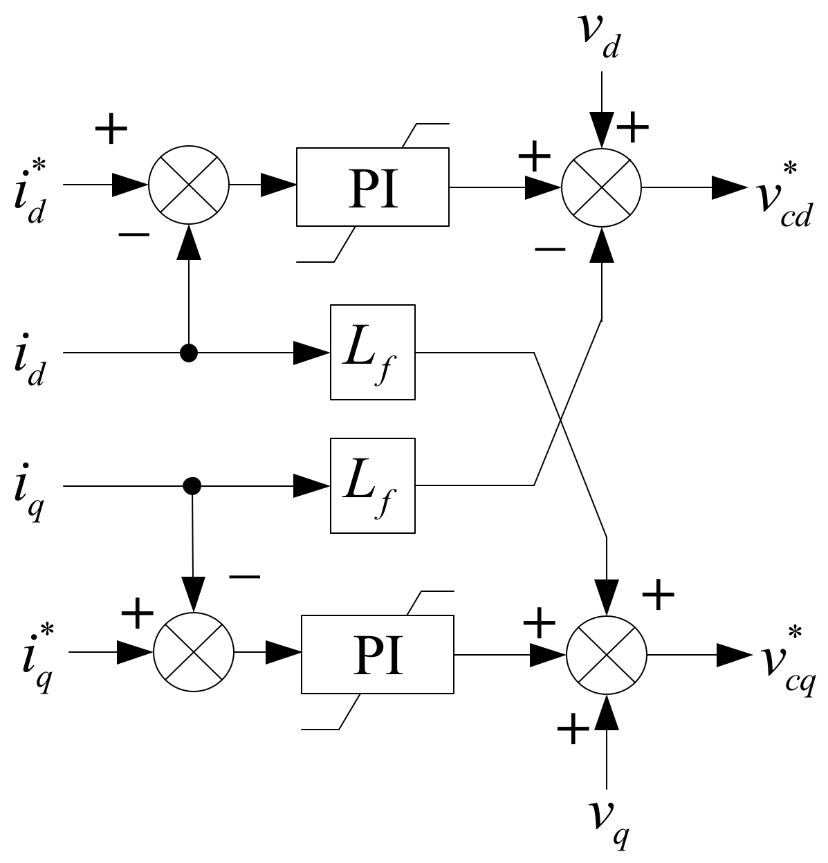
3.1.Voltage-Oriented Control (VOC)

VOC is based on the orientation of the control variables to a rotating dq reference frame orientated to the grid voltage. Based on this orientation, the VSC current d-axis and q-axis components can be used to regulate the VSC active and reactive power, respectively [4]. A block diagram of the implemented VOC system is depicted in Figure 3.
The voltage and current measured at the output of the VSC, vabc and iabc, are rotated to the phase of the grid voltage θ, which is obtained through a PLL. A sinusoidal pulse-width modulation (S-PWM) is assumed such that the output of the control systems is the reference voltage for the modulation of the VSC vc* [4]. vc* is orientated to the grid voltage to ensure that the generated voltage is synchronized with the grid. Therefore, the PLL objective is to orientate the reference dq axis to the measured grid voltage angle. A PLL can be implemented with a compensator that ensures that the quadrature component of the voltage becomes zero [4], as depicted in Figure 4.
The control of the current dq-components includes a decoupling between the d and q axes and feedforward of the voltage, as depicted in Figure 5.

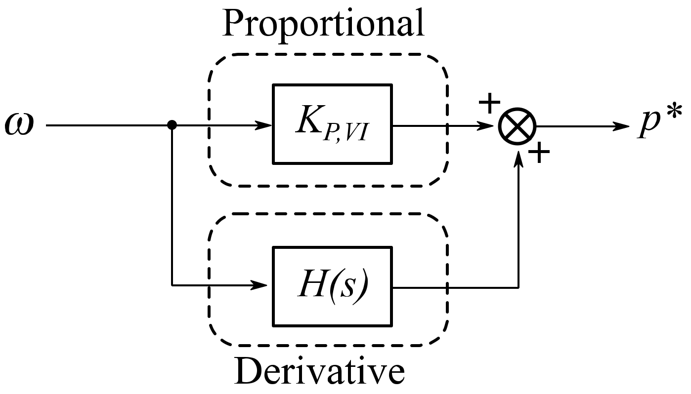
3.2.Virtual Inertia (VI)

The VI controller implemented in this paper was based on the model presented in Pradhan et al. [31], where the active power reference for the VOC is proportional to the MG frequency, as measured by the PLL, and to its derivative:
p * = ( K P , V I + K D , V I · H s ) · ω .
A schematic representation can be seen in Figure 6.
The resulting active power reference (p*) is used as the input of the active current loop of Figure 3. According to Pradhan et al. [31], the derivative term is included to provide a fast response, while the proportional term allows for the BESS to provide active power until the frequency is restored. As presented in Section 2.1, according to other authors, derivative and proportional terms are intended to emulate the behavior of the SG inertial and governor droop responses, respectively.
Despite the different interpretations, there is no analytical comparison of the resulting IR when including either derivative or proportional components in a VI scheme. This paper analyzes the effect of the derivative term by comparing the scheme in Figure 6, called “VI-PD” onwards, with a proportional-only “VI-P” system.
The frequency used for the control, ω, is usually passed through a deadband, which avoids the use of the BESS for small variations of the frequency around its normal operating point, which are considered admissible for operation [32,33]. The effect of this deadband was neglected in this study to ensure that the actuation of the VI solution was similar to the other solutions that do not use deadbands.
A filter of the frequency signal noise might also be needed. For this purpose, the PLL can be designed to filter frequency variations as a compromise with its speed [34]. Moreover, the calculation of the derivative of the frequency through H(s) may lead to undesired variations; therefore, it is usually implemented together with a low-pass filter [35]. In Arani and El-Saadany [36], a second-order filter is implemented as follows:
H s = s K D , V I s + τ 1 s + τ 2 .
As reported in Arani and El-Saadany [36], the transfer function in Equation (4) is already included in the proposed PLL implementation shown in Figure 4, meaning that vq is effectively a filtered estimation of the grid frequency derivative (sΔωg). The resulting PLL transfer function is a low-pass filter; thus, the estimation will only be accurate for variations below the PLL bandwidth. Therefore, in this work, vq was used as a filtered estimation of the grid frequency derivative. Since this estimation is only accurate for low-frequency variations, a first-order low-pass filter is also included.

3.3.Virtual Synchronous Machine (VSM)

The VSM implementation used in this paper was based on a simplified version of the synchronverter presented in Roldán-Pérez et al. [37]. The harmonic content elimination and the coupling between the frequency and voltage amplitude presented in Roldán-Pérez et al. [37] are omitted here since both power quality and reactive power control are out of the scope of the work. The resulting control system scheme is presented in Figure 7.
In contrast with the VOC of Figure 3, in this case, the angle θ used as a reference for the orientation of the VSC modulation voltage, vc*, is calculated directly from the control of the VSC active power p. The quadrature component of the modulation voltage, v*c,q, is fixed at 0 such that the amplitude is defined by the direct component v*c,d. v*c,d is used to regulate the VSC reactive power q. As noted in Roldán-Pérez et al. [37], this implementation resembles a direct power controller. The p and q controller schemes are depicted in Figure 8.
The active power controller is designed to emulate the swing equation of an SG. This ensures that the generated voltage frequency, ω, is equal to the grid frequency and that the voltage angle θ has the value required for power injection. This inherent synchronization mechanism in the active power control is what allows VSMs to operate without the use of a PLL [24].
The relation with the swing equation of SG can be obtained by analyzing the equation of the control loop presented in Figure 8a, which relates active power with frequency as follows:
p * p = 1 K P , V S M s ω D V S M ω * ω .
From the equation above, it can be seen that DVSM introduces a proportional relation between the BESS active power generation p and the frequency of the modulated voltage ω, while KP,VSM introduces a relation between the active power and the derivative of the frequency (). Note that the proportional and derivative terms in Equation (5) can be directly compared with the proportional and derivate terms of the VI implementation presented in Section 3.2
The control law given by the implemented VSM presented in Equation (4) can be compared with the small-signal model of a classical SG swing equation:
2 H Ω b s 2 Δ δ + D Ω b s Δ δ = Δ p m Δ p e ,
where δ is the angle between the VSC voltage and the grid voltage, H is the SG inertia constant, D the SG damping factor, pm the accelerating power, and pe the decelerating power (with power and torque assumed to be equivalent in pu) [19]. For small variations around ω = 1,
1 Ω b s Δ δ = Δ ω .
Therefore, Equation (5) can be written as:
1 Ω b K P , V S M s 2 Δ δ + D V S M Ω b s Δ δ = Δ p × Δ p
By comparing Equations (8) and (6), the value of KP,VSM to obtain an emulated inertia HV can be calculated using:
K P , V S M = 1 2 H V .
Therefore, KP,VSM can be used to emulate the desired level of the inertial response. However, on top of emulating the inertial response, KP,VSM also defines the VSM control dynamics. From Equation (8), the small-signal, open-loop transfer function of the VSM active power control can be calculated using:
Δ ω Δ p = 1 s K P , V S M + D V S M
Therefore, HV cannot be made arbitrarily big since as KP,VSM decreases, so does the frequency of the active power controller transfer function. This introduces a phase lag that reduces the phase margin (PM) of the system. This relation between the emulated inertia constant and the system stability can limit the practicability of VSM for IR. This will be analyzed in more detail in the results section.

4.Results and Discussion

This section gives the results of estimating the effect of the converter synchronizing method on IE from BESSs in an isolated MG application based on the models presented in Section 3. Time-domain simulations on an MG test system were used to obtain numerical results and assess the effects of the converter synchronizing method used in the PCS on IE provision from BESSs in an isolated MG.

4.1.Test System

A simple isolated MG, as depicted in Figure 9, was used as a test system for assessment. The MG consisted of one SG-based micro-source and a VSC-interfaced BESS feeding a local load (assumed to be static, represented by passive components), where the main parameters are shown in Table 1. Values in per unit (pu) refer to the MG nominal power and voltage.
The test system was implemented in a dynamic simulation using the MATLAB®-SimulinkTM SimPowerSystem toolbox R2016b (The MathWorks, Inc., Natick, Massachusetts, United States) to assess the system frequency response following a power imbalance. Due to the fast dynamics involved, dynamic simulations were required to analyze the time-domain behavior during the short period involved in IR [19].
The SG-based micro-source was implemented using a classic first-order model, including governor action to control the mechanical power (pm) injection to the SG. The governor included a PI governor system and a servomotor, as proposed in Demello et al. [38]. The governor was configured to perform a droop action between the power injection and the speed reference. The SG was rated relative to the MG nominal power. The SG parameters were based on the turbine and governor models presented in Kodama et al. [39].
The static load was modeled as a constant resistance and inductance (lagging power factor). Variations in load demand were performed by connecting additional resistances in parallel through a three-phase circuit breaker. The BESS was modeled using a VSC-averaged fundamental frequency model, including the control systems presented in Section 3 and connected to a constant DC voltage source.

4.2.Simulation Parameters

In this subsection, the parameters used in the implementation of the different systems are presented. This section includes an analysis of the different IE control system’s parameters such that they provide an equivalent emulated IR according to each solution’s version of “inertial response.”

4.2.1.VOC Parameters

The main parameters related to the VOC are summarised in Table 2. The PLL parameters were selected according to the natural frequency ωn and damping ξ of the resulting second-order closed-loop transfer function. The PLL bandwidth was selected based on a compromise between the synchronization speed and filtering characteristics, as proposed in Chung [40], while the damping coefficient ensured a compromise between the synchronization speed and damping. The current controllers’ PI gains depended on the MG characteristics in accordance with the zero-pole cancellation method proposed in Amirnaser and Reza [4].

4.2.2.VSM Parameters

The VSM parameters are the proportional gain of the active power controller KP,VSM, the damping gain DVSM, and the gain of the reactive power controller KQ,VSM.
The damping gain DVSM is referred to in some works as being analogous to the SG friction coefficient [8,37], while in others, it is interpreted as being analogous to the droop coefficient of the SG governor since it introduces a proportional relationship between frequency variations and an active power reference [41]. When used as analogous to a droop, DVSM is selected depending on the desired contribution to load variations and is usually imposed by the grid code [41]. According to EN 50438, it is required that the change of 100% active power corresponds to the change of 2% grid frequency, which gives DVSM = 0.5. Since the case study comprised an isolated MG, it was expected that the frequency presented more considerable variations than in bulk power systems. Thus, DVSM was selected experimentally to be DVSM = 9.0 such that the BESS could fully compensate for the simulated load variation in a steady state.
On the other hand, as discussed in Section 3.3, KP,VSM, is related to the emulated SG inertia constant, but it also determines the control bandwidth. From the open-loop transfer function of the active power controller presented in Equation (8), it can be found that, for a minimum PM of 45°:
K P , V S M m i n = ω c r o s s o v e r D V S M = 3.
which gives a maximum emulated inertia HV of about 0.17 s. Here, KP,VSM = 5.5 was selected to allow for a more significant PM and damping characteristics, such that HV = 0.10 s. This emulated inertia constant value is similar to the one obtained experimentally in other VSM implementations [37,41]. KQ,VSM can be selected depending on the required closed-loop time constant τQ,VSM as follows [37]:
K Q , V S M = 3 2 L τ Q , P L L .
A summary of the VSM parameters is included in Table 3.

4.2.3.VI parameters

A reference for the selection of VI parameters for grid-connected applications can be found in [31,42]. However, the parameter selection methods shown there are not directly applicable to this case study of an isolated MG. The parameters to be selected are the proportional gain KP,VI, the derivative gain KD,VI, and the deadband characteristics.
The proportional gain KP,VI is equivalent to the droop gain used in the governor of SG-based generation systems. Therefore, to make the controller comparable to the VSM implementation, it was selected to be equal to DVSM; therefore, KP,VI = 9.0.
From Equation (3), the derivative gain is related to the emulated inertia constant HV of the equivalent SG system such that KD,VI = 2HV [36]. Here, it was selected to provide the same inertia constant as the VSM implementation of 0.1 s; therefore, KD,VI = 0.2. The deadband should comprise the variations of frequency that are considered acceptable in normal operation. Based on Pradhan et al. [31], they were selected as ±0.2 Hz. Table 4 summarizes the selected parameters.

4.3.Simulation Results

In this section, the time-domain simulation of the frequency in the test system and the associated assessment of the effects of the converter synchronizing method on IE from BESSs is reported on.
First, a load variation was introduced into the MG test system. The implemented IE solutions attempted to compensate for this load variation providing active power. Then, the sensibility of the system to the steady-state relation between active power and frequency for the different solutions was addressed.
The synchronizing method and IE from BESSs to be compared were as follows: Case I, VOC—Regulation of the BESS active power using a PLL without any specific IE control system. Case II, VSM—IE through the emulation of an SG swing equation without the use of a PLL. Case III—IE based on measuring the grid frequency through a PLL and applying active power variations proportional to the frequency variations (proportional component) and the derivative of frequency variations (derivative component). Case IV, droop—The same implementation as Case III but with only the proportional component (droop action). The base case is the response without a BESS connected to the MG.

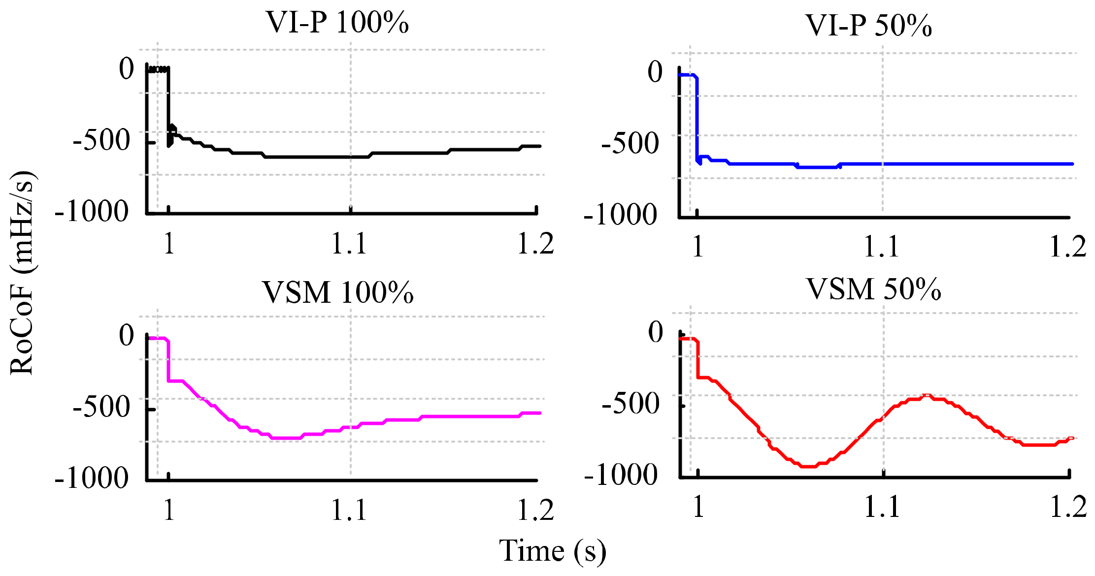
4.3.1.Response to Load Variation

A sudden step increase of the active power demand (0.1 pu) was used as the system frequency disturbance. The system frequency response for all cases is presented in Figure 10. The base and VOC (case I) cases had the worst system frequency responses, reaching the deepest fNADIR. The VI and VSM implementations exhibited a similar frequency response, reaching a smaller fNADIR and the same steady-state post-disturbance frequency.
Figure 11 shows the power delivered by the BESS, PBESS. Since IR is related to the first moments after the disturbance, a zoom of the first moments is highlighted in Figure 12. The initial PBESS response was similar between the VOC, droop, and VI systems, which had the PLL synchronizing method and internal current control loops in common. However, the VOC had no further frequency response, while for the droop and VI systems, the active power was maintained due to the external active power regulation loops. The similarity between the droop and VI shows that the effect of including a derivative component was not significant for the IR response.
For the VSM, the response of PBESS was significantly less damped since the dynamics introduced by the synchronizing method based on the emulation of the SG swing equation were significantly slower than the dynamics of the PLL-based solutions. This resulted in a higher value of PBESS for the VSM control compared to the droop and VI systems.
Due to the power delivered by the BESS after the disturbance, the SG was not required to contribute the same energy as in the base case. Therefore, the deceleration of the SG rotor was reduced. This effect can be seen in the rate of change of frequency (RoCoF) of the system. In this case, the RoCoF was calculated based on ENTSO-E [43] as the rate of change of the SG rotational speed for the simulation time step Δt:
R o C o F Δ t t i = ω t i + Δ t ω t i Δ t ,   i t 0 , t s .
The plot of the RoCoF variation for the different cases is shown in Figure 13. Again, the response in the 20 s time frame was similar for all cases. A zoom of the first moments after the variations is presented in Figure 14.
Under the VSM control system, the initial RoCoFΔt was lower. This shows the relation between the power delivered by the BESS and the resulting RoCoF. Since the VSM solution delivered a higher initial PBESS, the SG did not have to deliver as much energy and the deceleration (RoCoF) was reduced.
A summary of the main indicators used to assess the frequency response is presented in Table 5. Since RoCoF is usually measured on different time windows depending on the application, the RoCoF on a time window of 500 ms (RoCoF500ms) was also considered besides RoCoFΔt.
The VSM exchanged an extra 2% of energy due to its slower response of VSM, which meant that PBESS was maintained for a more extended period than in other cases. This effect can be seen in the active power response of Figure 12. This extra energy delivered by the BESS implies that the SG was not required to use as much kinetic energy from its rotor. Therefore, it can be seen that the VSM was more effective at supporting the inertia of the system than the VI and droop systems thanks to its slower response. On the other hand, both RoCoFΔt and RoCoF500ms were lower for VI, which affected the operation of systems that were sensible to RoCoF.
These results show how the different synchronizing mechanisms affected the expected emulated inertial response, especially in the first moments following a power imbalance. The PLL-based solutions responses were dominated by the internal current control and therefore were faster and less damped, while power-balanced-based systems presented a slower response due to the use of the emulated SG swing equation as a synchronizing mechanism, thus providing more energy to the system.

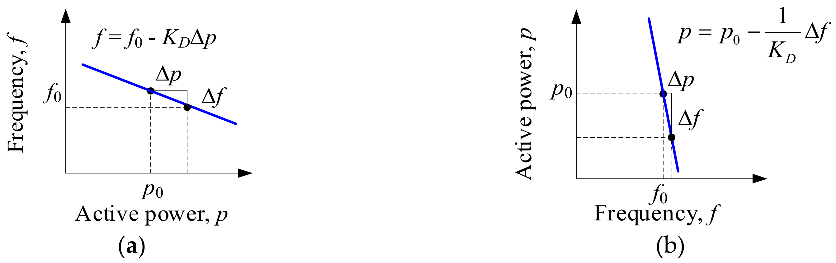
4.3.2.Sensitivity to the Steady-State Relation between the Active Power and Frequency

As noted in the analysis of the VSM solution in Section 3.3, the selection of the emulated IR parameters had a significant effect on the stability of the system. The influence of the steady-state relation between active power and frequency was addressed by reducing its value such that the BESS contribution in the steady state was reduced by 50%. In the following figures, the original case is referred to the 100% case, while the new case is referred to as the 50% case.
Note that this criterion can be used to define the proportional relation between active power and frequency in the droop, VI, and VSM control systems, as analyzed in Section 4.2. This implies that both DVSM and KP,VI were reduced from 9, as given by Table 3 and Table 4, respectively, to 2.
The comparison of the effect on the system frequency response (measured from the SG rotational speed) in the full 20.0 s time scal, is depicted in Figure 15. In this case, the fNADIR increased relative to the original case with a higher proportional relation since the BESS was not contributing as much to compensate for the power imbalance.
As in the original case, the frequency variation in the full 20.0 s time scale was similar for all the systems. Again, to study the first instants following the load variation, the RoCoFΔt is presented in Figure 16, while a zoom for the first moments following the load variation is shown in Figure 17. In this case, the difference in the system dynamics for the different inertia control implementations is more noticeable.
The VSM damping was reduced significantly due to the inherent relation between damping and the steady-state gain given by Equation (8). On the other hand, the effect on the droop and VI systems was significant for the steady-state value but not for the emulated IR, which was still dominated by the internal VOC, and thus the system dynamics were not compromised.
The comparison between Figure 14 and Figure 17 show that the use of different synchronizing mechanisms for IE could affect not only the resulting emulated inertial response, but also the system stability. In Figure 17, it can be seen how the RoCoF of the VSM was affected significantly by the change in the proportional gain between the active power and the frequency, with the RoCoF value for the new case reaching a minimum (higher absolute) value compared to the rest of the solutions. On the other hand, the effect on the RoCoF of the VI solution was not so noticeable.
These results validate the analytical model given by Equation (9), which shows the relationship between the proportional gain DVSM and the dynamic active power response. The same equations that guarantee the synchronism of the VSM solutions are the ones that guarantee the emulated inertial response. Accordingly, the same parameter that determines the steady-state relationship between frequency and power DVSM affected the stability of the system. PLL-based solutions response was less sensitive to the inertia support requirements since the synchronizing method was not coupled to inertia requirements.
Again, the inclusion of the derivative component in VI did not provide a significant effect since the response of the droop and VI systems was very close.

5.Conclusions

This study assessed the effect of the synchronizing method on the inertial response of BESSs. A literature review was provided to categorize the available inertia emulation solutions according to their synchronizing method. Representative solutions of both PLL-based and power-balanced based systems were modeled to evaluate their discrete-time implementation and a case study where a BESS was connected to an isolated MG was used to compare their inertial response through their contribution to the system stability. An analytical model for the different solutions was provided, including a guide for the selection of the control parameters for a given emulated IR. This methodology allowed for the analysis of the effect that a synchronizing mechanism had on inertia emulation control solutions and the associated stability problems.
Specifically, the presented analysis shows that there were differences between the emulated inertial response provided by solutions that used a PLL for synchronization and solutions where synchronization depended on the use of a VSM. Despite the equivalent inertial response parameters, differences emerged when the analysis was performed for the first instants following a load disturbance. For the PLL-based solutions, the initial response was dominated by the low-level current control, resulting in fast under-damped oscillations. The system response was similar, even when no specific emulated inertia response was considered, due to the internal control loops. Moreover, it was demonstrated that the effect of the derivative component was small, as the results for the VI and droop implementations are very close. The VSM presented a slower response than the VI and droop systems, thus providing more energy to the system that did not have to be extracted from the SG rotor kinetic energy.
The analysis of the VSM solutions show that there was a compromise between the inertia constant that could be emulated and the resulting dynamic performance of the BESS control system. Specifically, the results show that for the VSM, the proportional gain between active power and frequency not only affected the steady-state power contribution, but also the system stability, and therefore, cannot be set arbitrarily. This problem was not noticed for the VI and droop solutions, which led to a higher margin in the selection of the emulated inertial response.

Author Contributions

All authors have read and agreed to the published version of the manuscript.

Funding

This work was supported by the Autonomous Community of Madrid under the PROMINT-CM project (P2018/EMT-4366).

Conflicts of Interest

The authors declare no conflict of interest.

References

  1. Gonzalez-Longatt, F.; Chikuni, E.; Rashayi, E. Effects of the Synthetic Inertia from Wind Power on the Total System Inertia After a Frequency Disturbance. In Proceedings of the 2013 IEEE International Conference on Industrial Technology (ICIT), Cape Town, South Africa, 25–28 February 2013; pp. 826–832. [Google Scholar]
  2. Tamrakar, U.; Shrestha, D.; Maharjan, M.; Bhattarai, B.; Hansen, T.; Tonkoski, R. Virtual Inertia: Current Trends and Future Directions. Appl. Sci. 2017, 7, 654. [Google Scholar] [CrossRef]
  3. Chauhan, R.K.; Rajpurohit, B.S.; Hebner, R.E.; Singh, S.N.; Longatt, F.M.G. Design and Analysis of PID and Fuzzy-PID Controller for Voltage Control of DC Microgrid. In Proceedings of the 2015 IEEE Innovative Smart Grid Technologies—Asia, ISGT ASIA 2015, Bangkok, Thailand, 3–6 November 2015. [Google Scholar]
  4. Amirnaser, Y.; Reza, I. Voltage-Sourced Converters in Power Systems: Modeling, Control, and Applications; John Wiley & Sons: Hoboken, NJ, USA, 2010. [Google Scholar]
  5. Egea-Alvarez, A.; Fekriasl, S.; Hassan, F.; Gomis-Bellmunt, O. Advanced Vector Control for Voltage Source Converters Connected to Weak Grids. IEEE Trans. Power Syst. 2015, 30, 3072–3081. [Google Scholar] [CrossRef] [Green Version]
  6. Svensson, J. Synchronisation methods for grid-connected voltage source converters. IEE Proc.-Gener. Transm. Distrib. 2001, 148, 229. [Google Scholar] [CrossRef] [Green Version]
  7. Blaabjerg, F.; Teodorescu, R.; Liserre, M.; Timbus, A.V. Overview of control and grid synchronization for distributed power generation systems. IEEE Trans. Ind. Electron. 2006, 53, 1398–1409. [Google Scholar] [CrossRef] [Green Version]
  8. D’Arco, S.; Suul, J.A. Equivalence of virtual synchronous machines and frequency-droops for converter-based Microgrids. IEEE Trans. Smart Grid 2014, 5, 394–395. [Google Scholar] [CrossRef]
  9. Suul, J.A.; D’Arco, S.; Guidi, G. Virtual Synchronous Machine-Based Control of a Single-Phase Bi-Directional Battery Charger for Providing Vehicle-to-Grid Services. IEEE Trans. Ind. Appl. 2016, 52, 3234–3244. [Google Scholar] [CrossRef]
  10. Wang, D.; Meng, K.; Gao, X.; Qiu, J.; Lai, L.L.; Dong, Z.Y. Coordinated Dispatch of Virtual Energy Storage Systems in LV Grids for Voltage Regulation. IEEE Trans. Ind. Inform. 2018, 14, 2452–2462. [Google Scholar] [CrossRef]
  11. Lai, C.S.; McCulloch, M.D. Levelized cost of electricity for solar photovoltaic and electrical energy storage. Appl. Energy 2017, 190, 191–203. [Google Scholar] [CrossRef]
  12. National Grid Electrical Sytem Operator. Operability Strategy Report; National Grid Electrical Sytem Operator: Warwick, UK, 2018. [Google Scholar]
  13. Breithaupt, T.; Tuinema, B.; Herwig, D.; Wang, D.; Hofmann, L.; Rueda Torres, J.; Mertens, A.; Rüberg, S.; Meyer, R.; Sewdien, V.; et al. MIGRATE Deliverable D1.1-Report on Systemic Issues; MIGRATE Project Consortium: Bayreuth, Germany, 2016; p. 137. [Google Scholar]
  14. D’Arco, S.; Suul, J.A. Virtual Synchronous Machines—Classification of Implementations and Analysis of Equivalence to Droop Controllers for Microgrids. In Proceedings of the 2013 IEEE Grenoble Conference PowerTech, POWERTECH 2013, Grenoble, France, 16–20 June 2013; pp. 1–7. [Google Scholar]
  15. Mo, O.; D’Arco, S.; Suul, J.A. Evaluation of Virtual Synchronous Machines with Dynamic or Quasi-Stationary Machine Models. IEEE Trans. Ind. Electron. 2016, 64, 5952–5962. [Google Scholar] [CrossRef] [Green Version]
  16. Kottick, D.; Blau, M.; Edelstein, D. Battery Energy Storage for Frequency Regulation in an Island Power System. IEEE Trans. Energy Convers. 1993, 8, 455–459. [Google Scholar] [CrossRef]
  17. Morren, J.; de Haan, S.W.H.; Kling, W.L.; Ferreira, J.A. Wind turbines emulating inertia and supporting primary frequency control. IEEE Trans. Power Syst. 2006, 21, 433–434. [Google Scholar] [CrossRef]
  18. Mauricio, J.M.; Marano, A.; Gomez-Exposito, A.; Martinez Ramos, J.L. Frequency Regulation Contribution Through Variable-Speed Wind Energy Conversion Systems. IEEE Trans. Power Syst. 2009, 24, 173–180. [Google Scholar] [CrossRef]
  19. Kundur, P.; Balu, N.J.; Lauby, M.G. Power System Stability and Control; McGraw-Hill: New York, NY, USA, 1994; Volume 7. [Google Scholar]
  20. Sun, Y.; Zhang, Z.; Li, G.; Lin, J. Review on Frequency Control of Power Systems with Wind Power Penetration. In Proceedings of the 2010 International Conference on Power System Technology, Hangzhou, China, 24–28 October 2010; pp. 1–8. [Google Scholar]
  21. Ma, J.; Qiu, Y.; Li, Y.; Zhang, W.; Song, Z.; Thorp, J.S. Research on the impact of DFIG virtual inertia control on power system small-signal stability considering the phase-locked loop. IEEE Trans. Power Syst. 2017, 32, 2094–2105. [Google Scholar] [CrossRef]
  22. Beck, H.; Hesse, R. Virtual Synchronous Machine. In Proceedings of the 2007 9th International Conference on Electrical Power Quality and Utilisation, EPQU, Barcelona, Spain, 9–11 October 2007; pp. 1–6. [Google Scholar]
  23. Zhong, Q.C.; Weiss, G. Synchronverters: Inverters that mimic synchronous generators. IEEE Trans. Ind. Electron. 2011, 58, 1259–1267. [Google Scholar] [CrossRef]
  24. Zhong, Q.C.; Nguyen, L.; Ma, Z.; Sheng, W. Self-synchronized synchronverters: Inverters without a dedicated synchronization unit. IEEE Trans. Power Electron. 2014, 29, 617–630. [Google Scholar] [CrossRef]
  25. Zhang, L.; Harnefors, L.; Nee, H. Power-synchronization control of grid-connected voltage-source converters. IEEE Trans. Power Syst. 2010, 25, 809–820. [Google Scholar] [CrossRef]
  26. Guerrero, J.M.; Chandorkar, M.; Lee, T.L.; Loh, C. Advanced control architectures for intelligent microgrids. Part I: Decentralized and hierarchical control. IEEE Trans. Ind. Electron. 2013, 60, 1254–1262. [Google Scholar]
  27. Zhong, Q.C. Robust droop controller for accurate proportional load sharing among inverters operated in parallel. IEEE Trans. Ind. Electron. 2013, 60, 1281–1290. [Google Scholar] [CrossRef]
  28. Yu, M.; Roscoe, A.J.; Booth, C.D.; Dysko, A.; Ierna, R.; Zhu, J.; Urdal, H. Use of an Inertia-Less Virtual Synchronous Machine within Future Power Networks with High Penetrations of Converters. In Proceedings of the 19th Power Systems Computation Conference, PSCC 2016, Genoa, Italy, 20–24 June 2016; pp. 1–7. [Google Scholar]
  29. Chandorkar, M.C.; Divan, D.M.; Adapa, R. Control of parallel connected inverters in standalone ac supply systems. IEEE Trans. Ind. Appl. 1993, 29, 136–143. [Google Scholar] [CrossRef]
  30. Aouini, R.; Marinescu, B.; Kilani, K.B.; Elleuch, M. Synchronverter-Based Emulation and Control of HVDC Transmission. IEEE Trans. Power Syst. 2016, 31, 278–286. [Google Scholar] [CrossRef]
  31. Pradhan, C.; Bhende, C.N.; Samanta, A.K. Adaptive virtual inertia-based frequency regulation in wind power systems. Renew. Energy 2018, 115, 558–574. [Google Scholar] [CrossRef]
  32. Keung, P.K.; Li, P.; Banakar, H.; Ooi, B.T. Kinetic energy of wind-turbine generators for system frequency support. IEEE Trans. Power Syst. 2009, 24, 279–287. [Google Scholar] [CrossRef]
  33. Delille, G.; François, B.; Malarange, G. Dynamic frequency control support by energy storage to reduce the impact of wind and solar generation on isolated power system’s inertia. IEEE Trans. Sustain. Energy 2012, 3, 931–939. [Google Scholar] [CrossRef]
  34. Ortega, Á.; Milano, F. Comparison of Different PLL Implementations for Frequency Estimation and Control. In Proceedings of the 2018 18th International Conference on Harmonics and Quality of Power (ICHQP), Ljubljana, Slovenia, 13–16 May 2018; pp. 1–6. [Google Scholar]
  35. Van de Vyver, J.; De Kooning, J.D.; Meersman, B.; Vandevelde, L.; Vandoorn, T.L. Droop Control as an Alternative Inertial Response Strategy for the Synthetic Inertia on Wind Turbines. IEEE Trans. Power Syst. 2016, 31, 1129–1138. [Google Scholar] [CrossRef]
  36. Arani, M.F.M.; El-Saadany, E.F. Implementing virtual inertia in DFIG-based wind power generation. IEEE Trans. Power Syst. 2013, 28, 1373–1384. [Google Scholar] [CrossRef]
  37. Roldán-Pérez, J.; Prodanovic, M.; Rodríguez-Cabero, A. Detailed Discrete-Time Implementation of a Battery-Supported Synchronverter for Weak Grids. In Proceedings of the IECON 2017—43rd Annual Conference of the IEEE Industrial Electronics Society, Beijing, China, 29 October–1 November 2017; pp. 1083–1088. [Google Scholar]
  38. Demello, F.P.; Koessler, R.J.; Agee, J.; Anderson, P.M.; Doudna, J.H.; Fish, J.H.; Hamm, P.A.L.; Kundur, P.; Lee, D.C.; Rogers, G.J.; et al. Hydraulic-Turbine and Turbine Control-Models for System Dynamic Studies. IEEE Trans. Power Syst. 1992, 7, 167–179. [Google Scholar]
  39. Kodama, H.; Sugiyama, T.; Morimoto, Y.; Oya, Y.; Okuno, K.; Inoue, N.; Sagara, A.; Noda, N. Thermal Annealing Effects on Chemical States of Deuterium Implanted into Boron Coating Film; McGraw-Hill: New York, NY, USA, 2003; pp. 313–316. [Google Scholar]
  40. Chung, S.-K. A phase tracking system for three phase utility interface inverters. IEEE Trans. Power Electron. 2000, 15, 431–438. [Google Scholar] [CrossRef] [Green Version]
  41. Wu, H.; Ruan, X.; Yang, D.; Chen, X.; Zhao, W.; Lv, Z.; Zhong, Q.C. Small-signal modeling and parameters design for virtual synchronous generators. IEEE Trans. Ind. Electron. 2016, 63, 4292–4303. [Google Scholar] [CrossRef]
  42. Shi, K.; Ye, H.; Song, W.; Zhou, G. Virtual Inertia Control Strategy in Microgrid Based on Virtual Synchronous Generator Technology. IEEE Access 2018, 6, 27949–27957. [Google Scholar] [CrossRef]
  43. ENTSO-E. Frequency Measurement Requirements and Usage; ENTSO-E: Brussels, Belgium, 2018. [Google Scholar]
Figure 1. Representative block diagram of the synchronizing method used in inertia emulation (IE) for Battery Energy Storage Systems applications: (a) phase-locked loop (PLL)-based and (b) power-balance-based.
Energies 13 01478 g001
Figure 2. Comparison of the operational characteristics according to the droop action: (a) synchronous generator governors and (b) virtual inertia (VI) systems.
Energies 13 01478 g002
Figure 3. Voltage-oriented control (VOC) based on the measurement of the grid voltage angle through a PLL. MG: Microgrid, VSC: Voltage Source Converter.
Energies 13 01478 g003
Figure 4. Block diagram showing PLL implementation based on orientating the reference axis to the measured grid voltage such that the quadrature component of the voltage, vq, becomes zero.
Energies 13 01478 g004
Figure 5. Block diagram showing the current controller implementation scheme.
Energies 13 01478 g005
Figure 6. Block diagram showing the VI scheme.
Energies 13 01478 g006
Figure 7. Scheme of the proposed virtual synchronous machine (VSM) implementation.
Energies 13 01478 g007
Figure 8. Control of active (a) and reactive (b) power in the implemented VSM.
Energies 13 01478 g008
Figure 9. Test system: MG case study. SG: Synchronous generator.
Energies 13 01478 g009
Figure 10. Frequency response as measured by the SG speed variation for VOC (black, solid line), VSM (red, * marked), VI (green, circle marked), and droop (blue, + marked) control systems, as well as no BESS connection (magenta, × marked).
Energies 13 01478 g010
Figure 11. BESS active power variation on load change for VOC (black, solid line), VSM (red, * marked), VI (green, circle marked), and droop (blue, + marked) control systems, as well as no VSC connection (magenta, × marked).
Energies 13 01478 g011
Figure 12. Zoom of BESS active power variation due to a load change. VI-P and VI-PD are the proportional and derivative components of VI, respectively.
Energies 13 01478 g012
Figure 13. Rate of change of frequency (RoCoFΔt) variation on load change for VOC (black, solid line), VSM (red, * marked), VI (green, circle marked), and droop (blue, + marked) control systems, as well as no VSC connection (magenta, × marked).
Energies 13 01478 g013
Figure 14. Zoom of the RoCoFΔt variation on the load change.
Energies 13 01478 g014
Figure 15. Comparison between frequency responses (based on SG speed variation): VSM (red, * marked), VI (green, circle marked), and droop (blue, + marked) control systems if the BESS assumed 50% of the load variation, as well as if it assumed 100% with a droop control system (black, solid line).
Energies 13 01478 g015
Figure 16. Comparison between the SG speed RoCoFtp on load change for VSM (red, * marked), VI (green, circle marked), and droop (blue, + marked) control systems if the BESS assumed 100% of the load variation versus 50% with droop (black, × marked) and VSM (magenta, square marked) control systems.
Energies 13 01478 g016
Figure 17. Zoom of the RoCoFΔt variation on the load change if the BESS assumed 100% of the load variation versus 50%.
Energies 13 01478 g017
Table 1. Electrical parameters of the test system MG.
LabelDescriptionValueUnits
SNMicrogrid nominal power500kW
UNMicrogrid nominal rms line voltage400V
pL,0Initial load active power demand0.2pu
pSG,0Initial active power of the SG0.2pu
pBESS,0Initial BESS active power0.0pu
fNMicrogrid nominal frequency50Hz
tpSample time of the power circuit10ms
LGThe equivalent inductance of the connection between the SG and the load0.1pu
LFEquivalent inductance of the connection between the BESS and the load0.2pu
RFEquivalent resistance of the connection between the BESS and the load0.004pu
SSG,NSG nominal power500kW
HSGSG inertia constant3.70s
KD,SGSG damping factor0.10pu
Table 2. Summary of VOC parameters.
LabelDescriptionValueUnits
TsController sampling time100.0μs
fn,PLLPLL natural frequency100.0Hz
ξPLLPLL damping coefficient1/√2-
τiTime constant of the current regulation loops1.0ms
KiGain of the current regulation loopsRF/LF-
Table 3. Summary of VSM parameters.
LabelDescriptionValueUnits
KP,VSMVSM active power controller gain5.5s−1
DVSMVSM damping gain9.0-
τQ,VSMVSM reactive power time constant10ms
Table 4. Summary of VI parameters.
LabelDescriptionValueUnits
KP,VIVI proportional gain9.0-
KD,VIVI derivative gain0.2s
Table 5. Summary of main systems’ performance indicators.
IndicatorVOCDroopVIVSM
fNADIR (Hz)47.02849.44849.44849.448
RoCoFDt (mHz/s)682.96609.10613.35700.89
RoCoF500ms (mHz/s)666.84502.31494.23495.74
PBESS,max (pu)0.040,100.100.10
E (pu·s)0.001.791.791.81

