Abstract
Active power filters (APFs) are dynamic power electronic devices that suppress harmonics and reactive power. To simplify the detection and extraction of traditional APF harmonics and reactive current, this paper proposes a direct source current control based on a three-phase three-wire shunt APF. The compensation principle and control method of the source current are analyzed systematically. The currents can be controlled without static errors by a proportional-integral (PI) controller in d-q rotating coordinates. Therefore, the compensation accuracy and dynamic performance of the system can be improved by the control strategy. Moreover, considering the grid voltage fluctuations, a droop regulator is proposed to address the impact of DC-link voltages on APF power losses and compensation performance. The regulator is combined with a traditional voltage outer loop PI control to achieve a comprehensive optimization between the power loss and compensation performance of the APF system. Finally, the inner current loop and the outer voltage loop form a double closed-loop cascade PI control structure to achieve the control effect of the APF. Simulation and experimental results verified the validity and feasibility of the APF control approach.
1. Introduction
In recent years, the widespread use of dynamic power electronic equipment and the increase in nonlinear impact loads in the power grid have caused serious power quality and harmonic problems. Active power filters (APFs) are widely used for the dynamic suppression of harmonics and reactive power due to their good filtering characteristics, small size, and flexible application. In particular, APFs based on instantaneous reactive power theory have become a popular research topic and they have been used for the development of power system harmonic suppression [1]. It is generally believed that the methods used for detecting harmonics and reactive power determine the accuracy of harmonic current detection, and then affect the compensation effect of an APF. Therefore, optimization control based on harmonic currents or reactive power detection [2,3,4,5,6,7] remains a focus of APF research. A traditional APF adopts harmonic current control methods. Because load current harmonics have the characteristics of high frequency and rapid change, it is difficult for general controllers to track these harmonics without static errors. Therefore, the recently proposed APF control method for directly controlling source currents has attracted widespread attention because it does not need to detect the load current harmonics and reactive currents. In [8,9], the load current harmonics and reactive currents were considered to be feedforward signals of capacitor voltages, and it was concluded that the load harmonic detection was unnecessary. In [10], a scheme for only detecting and controlling the source current was proposed. A simulation result showed that an APF could filter harmonics and reactive power without detecting harmonics. Based on the above research, a mathematical model of APF source current detection can be established, and a compensation principle and control method can be systematically analyzed. This approach can achieve tracking control without static errors through a proportional-integral (PI) controller.
For active power filters, an outer-loop control system composed of DC-link capacitor voltages is important for implementing the APF compensation effect [11,12]. There are active losses in both DC-link capacitors and power modules during APF operation. Meanwhile, in complex industrial applications load fluctuations will cause grid voltage fluctuations at the APF common coupling point, which will affect the compensation performance of the APF. In [13], the stability of DC-link capacitor voltage was a prerequisite for the optimal compensation of harmonic currents using an APF. Several commonly used control methods have been used to maintain the stability of DC-link capacitor voltages, including traditional PI control [14], adaptive PI control [15], fuzzy PI control [10,16], and sliding mode PI control [17,18]. In [19,20], the normal operation of an APF was preconditioned on the DC-link voltage value being greater than the peak value of the system side line voltage, and a minimum DC-link voltage was required to maintain the linear modulation range. In [1,21], the influence of the DC-link voltage standard value (the voltage reference value is the effective value of the grid phase voltage) on the APF compensation performance was analyzed, and a general scheme for designing a DC-link voltage rating was proposed. Many scholars focused on stabilizing the DC-link voltage at a fixed value, which does not change with the change in the grid voltage. When the grid voltage changes, the DC-link voltage should change with the grid voltage to improve the compensation performance and reduce power losses of the APF. In summary, the value and control strategy of the DC-link voltage must comprehensively consider the compensation performance and power loss of the APF.
This study used a three-phase three-wire shunt APF as an example. First, a mathematical model of APF source current control was established, and the basic principle of source current control was analyzed. Then, through feedforward and decoupling control, a double closed-loop cascade control structure of the voltage outer loop and the current inner loop was realized. Moreover, the relationship between DC-link voltage and APF power loss and compensation performance was analyzed. A scheme for controlling the DC-link voltage command value with a droop controller was proposed to optimize the DC-link voltage and balance the power loss and compensation performance of the APF system. Finally, the validity and feasibility of the proposed control scheme were verified by simulation and the experimental results.
2. Materials and Methods
2.1. Basic Principle of APF Source Current Control
A topology of the shunt APF system that uses the voltage source inverter is shown in Figure 1. Six insulated-gate bipolar transistors (IGBTs) form an inverter bridge. The nonlinear load consists of a three-phase uncontrolled rectifier bridge, an external resistor Rn and an inductor Ln. The DC-link voltage Udc is provided by the DC side energy storage capacitor C. The AC side is integrated into the grid through the filter side inductor L. R is the equivalent loss resistance of the filter inductor. RL is the load effect caused by the APF switching loss. N is the ground point on the DC side. O is the midpoint of the three-phase grid.
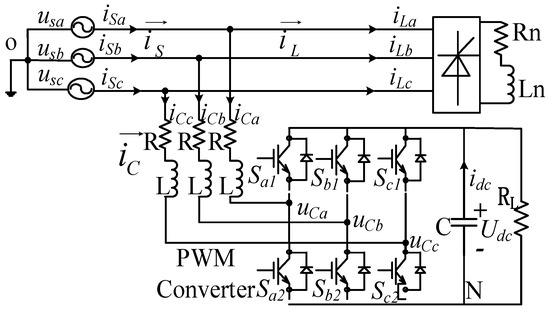
Figure 1.
Topology of shunt-type active power filters (APF).
Assuming that the three-phase three-wire shunt APF is a balanced system, according to Kirchhoff laws, the mathematical model of an APF in a-b-c coordinate system [22,23] is shown in Equation (1).
where iCa, iCb, and iCc are the APF output currents, uSa, uSb, and uSc are the three-phase grid voltages, Sa, Sb, and Sc are the duty cycles of six switches, and (i is a, b, or c). From the topology of the shunt APF and the meaning of each current, we can obtain Equation (2).
The basic principle of source current control is to directly control the source current iS of the APF system. The fundamental active component iLp of the detected load current is used as a command current. Then, it is compared with the actual source current iS to control the source current and track changes in the command current. Finally, harmonic compensation control is achieved. The grid current only contains the active component of the fundamental wave.
To study the basic principle of APF source current control more specifically and accurately, by using Equations (1) and (2) and the abc-dq transformation (3), the mathematical model of APF source current direct control is transformed from a three-phase a-b-c coordinate system to a two-phase rotating d-q coordinate system as shown in Equation (4).
where, ω is the grid angular frequency, iSd and iSq are the d-, and q-axis components of the source current, respectively, iLd and iLq are the d-, and q-axis components of the load current, respectively, uSd and uSq are the d- and q-axis components of the grid voltage, respectively, and Sd and Sq are the d- and q-axis components of the switching function duty cycle Si, respectively. Equation (4) reflects the principle of direct control of the source current.
The source current control is mainly composed of the compensation current control link and the DC-link voltage control. Based on the control target of the APF, the compensation performance and the mathematical model, the double closed-loop cascade control strategy of a voltage outer loop and a current inner loop is commonly used. The control of the DC-link voltage outer loop is added to the current link control, and the DC-link voltage is stabilized by the current inner loop control. The inner current loop separates the d-q axes from each other by decoupling and controls the d-axis and the q-axis separately. In addition, a feedforward channel is used to offset the amount of disturbance, and the d-q axis components are the DC component so that the PI regulator can be used to achieve non-static error control. This approach has the advantages of simple design and easy digital implementation.
A system block diagram of shunt APF source current control is illustrated in Figure 2, where Udc* is the command value of the DC-link voltage. The difference between Udc* and the sampled value Udc is passed through the voltage PI regulator to obtain the adjustment signal ΔiSd. ΔiSd is then superimposed on the d-axis component of the source current command. The DC component on the d-axis represents the fundamental active current. Then, ΔiSd determines the active power exchange on the AC and DC sides of the APF system.
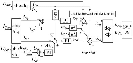
Figure 2.
Control system diagram of APF based on source current direct control.
The system uses the sum of the output ΔiSd of the DC-link voltage controller and the fundamental active component of the load current as the active reference value iSd* of the source current. The system detects the actual source currents iSd and iSq and compares them with the reference values iSd* and iSq*. Through the PI regulator and the grid voltage and load current feedforward correction, the voltage vector reference values urd and urq can be obtained. iCd and iCq are the APF output currents in d-q rotating coordinates and are used for feedforward decoupling control. Then, urα and urβ are obtained by d-q/α-β transformation, and they are sent to the space vector pulse width modulation (SVPWM) module. Finally, the PWM pulse signal output by the SVPWM module controls the breaking of the switching devices to achieve the source current direct control of the APF.
2.2. DC-Link Voltage Control of APF
2.2.1. Voltage Outer Loop Control Principle and Design
Part of the active current provided by the power supply is consumed by nonlinear loads, and the other part is absorbed by the APF to maintain the stability of DC-link voltages. The voltage outer loop generally uses a PI controller to stabilize the DC-link voltage [19,24]. However, in [19,25], the normal operation of the APF and its DC-link voltage requirements in the linear modulation range were given, and the relationship between the DC-link voltage and the APF compensation performance was analysed. In [26], the relationship between the magnitude of the DC-link voltage and the APF power loss and compensation performance was analyzed. Increasing the DC-link voltage will increase the power loss, and reducing the DC-link voltage will decrease the compensation capacity of APFs. Therefore, DC-link voltage control is a key factor that limits APF compensation performance and power losses.
2.2.2. Influence of DC-Link Voltage on APF Power Losses and System Compensation Performance
The APF power losses mainly include the hysteresis loss of the output inductor, copper loss [27], the switching device loss of the PWM inverter [28] and conduction power losses of inverters. In general, the hysteresis loss of the output inductor is mainly proportional to the switching ripple current contained in the APF output current [29]. The hysteresis loss of the output inductor can be reduced to a relatively low value with a magnetic material with high magnetic permeability. Therefore, the switching loss of IGBTs included in the PWM inverter and the diode reverse recovery losses are the main components of power losses. Meanwhile, when the switching frequency and APF output currents are fixed and constant, the DC-link voltage and power losses of the APF are synchronously changed. This means that the power loss of the APF increases as the DC-link voltage increases and decreases as the DC-link voltage decreases.
In [20], a precondition for the normal operation of an APF was offered showing that the DC-link voltage value is greater than the peak value of the system side line voltage. It is assumed that the output currents and output voltages of an APF are analyzed under the condition that the three-phase balanced power grid and the inductive load current of the three-phase uncontrolled rectifier only contain 6n ± 1 positive and negative sequence harmonic components. The harmonic components of the APF output current are determined by the harmonic components of the PWM inverter output voltage and the grid voltage. According to the SVPWM modulation principle, the PWM inverter amplitude modulation ratio M is defined as equal to the ratio of the modulus length Ur of the output voltage composite vector to half of the DC-link voltage average value Udc [24].
where,
where, Uf1m is the peak value of the fundamental wave component of the output phase voltage of the PWM inverter. Ufkm and Uflm are the peak values of the kth and lth harmonic components of the output phase voltage of the PWM inverter, respectively, and each φ represents the initial phase angle of each order component. Considering the full compensation of the nonlinear load in the worst case, the PWM inverter must output a maximum value exceeding the above voltage vector, Ur ≥ Ur|max. where the maximum value of Ur is Ur|max.
Therefore,
where, Usm is the peak value of the grid phase voltage. Ifkm and Iflm are the peak values of the kth and lth harmonic components of the APF output current, respectively. According to the linear working range of SVPWM space vector modulation [30], . Assuming that the amplitude modulation ratio M is always equal to the maximum value of 1.1547 when the APF is working, Equation (8) can be expressed as Equation (9).
According to the above analysis, UΔ determines the ability of an APF to output harmonic currents, and the required harmonic voltage component of the PWM inverter increases as the order of harmonics increases. Therefore, the compensation performance of an APF is related to the value of UΔ.
In the SVPWM linear modulation range, if the modulation ratio M is constant, the compensation ability of an APF can be improved with the increase of DC-link voltage; the compensation ability of an APF can be reduced with the decrease of DC-link voltage. At industrial sites, the grid voltage generally has a fluctuation of 90%–110% over a long period of time [24]. Therefore, when the grid voltage is reduced, the compensation capability of the APF can be improved. When the grid voltage is increased, the compensation capability of the APF will be reduced. When the DC-link voltage of the APF is constant, the grid voltage controls the compensation capability of the APF.
2.2.3. Design of Droop Regulator
Considering the actual grid fluctuation, the power loss of an APF needs to be effectively reduced under the condition of ensuring the harmonic compensation ability of the APF. Based on Equation (9), a droop regulator can be designed to control the command value of the DC-link voltage to realize the comprehensive optimization of the power loss and the compensation performance of the APF. When the grid voltage is high, the DC-link voltage value is increased to ensure the compensation performance of the APF. When the grid voltage is low, the DC-link voltage value is reduced to decrease the power loss of the APF. Considering either a rise in grid voltage or a sudden increase in load, given a certain margin, the droop regulator can be expressed as Equation (10).
where, Udcn is the assumed value of the DC-link voltage when the APF can achieve the compensation effect, which is 700 V. Usn is the effective value of rated grid phase voltage, which is 220 V. Considering that the grid voltage fluctuation range is ±10%, the curve of the DC-link drop regulator can be drawn according to Equation (9), as shown in Figure 3.
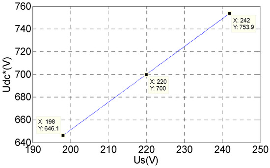
Figure 3.
Reference value of DC-link voltage by droop regulator.
The DC-link voltage range at this moment is 646 V–754 V. The control strategy of the APF DC-link voltage command value using a droop regulator is shown in Figure 4. The grid voltage is transformed from a-b-c to d-q coordinates, and then passed through the droop controller to obtain the reference voltage Udc*. After a comparison with the actual sample value Udc, the active current adjustment signal ΔiSd is output by the PI regulator. Then ΔiSd is introduced into the inner current loop to maintain the stability of the DC-link voltage. Finally, the double closed-loop control of the APF is realized.
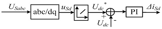
Figure 4.
Voltage loop control diagram of APF with a droop controller in the d-q reference frame.
From Figure 4, the output of the voltage outer loop PI controller is shown in Equation (11).
where, KVp and KVi are the proportional coefficient and the integral coefficient of the voltage outer loop PI regulator, respectively. Udc* is the command value of the DC-link voltage after passing through the droop regulator.
2.3. Current Inner Loop Control Principle and Design
According to the mathematical model of an APF in d-q coordinates, there is a serious coupling phenomenon between the d-axis and the q-axis. It is necessary to use the state feedback decoupling control based on the d-q rotating coordinate system [31]. The current states of the d-axis and the q-axis are introduced in d-q coordinates, and the state decoupling control between the d-, and q-axes is realized by the state feedback matrix. In addition, the interference input of the grid voltage uSd, uSq and the load currents iLd, iLq must also be considered and can be achieved by feedforward compensation. The disturbance compensation for the grid voltage can be directly offset by a unit feedback channel. Because the load current contains multiple harmonics, when ordinary PI controllers cannot completely suppress them, it is necessary to design a suitable load current feedforward transfer function. Finally, a full compensation of the load current disturbance error is realized through the load current disturbance feedforward compensation channel. Therefore, after the output current decoupling and the grid voltage and load current feedforward compensation correction, the controller outputs are urd and urq, as shown in Equation (12).
After collating,
where vrd and vrq are the d- and q-axis components of the current loop controller, respectively, and the controlled object source current is decoupled and corrected to be a first-order model. Then, the source currents iSd and iSq can be separately controlled by controlling vrd and vrq. Generally, the current inner loop uses a PI controller. Because the DC-link voltage passed the voltage outer loop PI controller is the DC component. Then, the DC-link voltage plus the fundamental active component of the load current (DC component in d-q coordinates) is still the DC component. Therefore, the PI controller can be used for current inner loop control to realize tracking without static errors. Let KIp and KIi be the proportional coefficient and integral coefficient of the inner loop PI regulator, respectively. The current loop controller output is shown in Equation (14).
Based on the previous analysis, according to the simplified mathematical model of the decoupling of the APF system in d-q coordinates and the grid voltage and the load current feedforward control, and considering the influence of the converter and current sampling, etc., the control block diagram of the current inner loop in the d-axis can be obtained as shown in Figure 5.
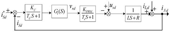
Figure 5.
The current loop of the d-axis control diagram.
According to the typical type II system, the controller parameters KIp and KIi are designed based on the “oscillation index method” [32] to ensure that the performance index of the system does not exceed a certain value. That is, the maximum overshoot of the system will not be greater than a certain limit, the corresponding phase angle margin is the largest, the amplitude margin is the most suitable, and the corresponding adjustment time is the shortest. From Figure 5, we can obtain the closed-loop transfer function of the d-axis of the voltage inner loop which is a type II control system. Similarly, the PI parameters KVp and KVi of the voltage outer loop controller can be obtained.
3. Results
3.1. Simulation Results and Analysis
To verify the correctness of the proposed scheme, a model based on source current detection was built in Simulink for simulation analysis. The simulation parameters are as follows: the grid voltage Us = 220 V, the grid frequency f = 50 Hz, the connected reactor is 0.5 mH, the reactor internal resistance is 0.5 Ω, the DC-link rated voltage value Udc = 700 V, the equivalent capacitance is 20 mF/900 V, the load is a three-phase uncontrolled rectifier with a resistive load (6 Ω), and the switching frequency is 9600 Hz. PI parameters Kip = 50, Kii = 11, Kvp = 1.6, Kvi = 30.
A comparative analysis of Figure 6a,b shows that the source current after the APF compensation is essentially a sine wave based on the source current control strategy. The total harmonic distortion (THD) of the source current decreases from 26.7% to 2.29% after the APF compensation.
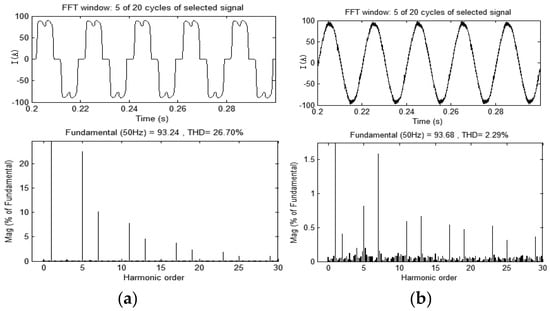
Figure 6.
Simulation waveforms of APF with source current control method. (a) Load current and its distortion rate before APF application; (b) Source current and its distortion rate after APF application.
The verification of the dynamic response performance of the APF based on the source current control shows the dynamic process of the system when the harmonic load is suddenly added or lost. The load was suddenly applied at 0.1 s, and suddenly lost at 0.3 s. The corresponding waveforms are illustrated in Figure 7a–c. The APF can quickly track the change in the command current. Its dynamic response occurs within 15 ms, and full compensation is reached at approximately 30 ms.
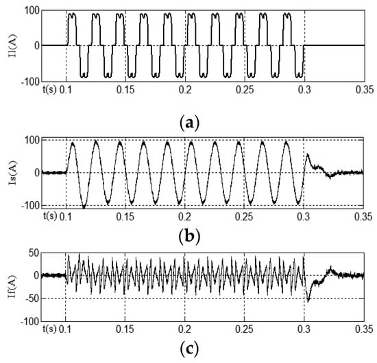
Figure 7.
Dynamic performance of the APF system. (a) Load current Il; (b) Source current Is; (c) Harmonic current If.
The waveforms of the APF output DC-link voltage using the droop controller is shown in Figure 8a–c. At 0–0.4 s, the effective value of the grid phase voltage is 90% of the rated value, and the DC-link voltage is adjusted to 646 V. At 0.4–0.8 s, the APF works at the rated value of the grid voltage, and the DC-link voltage is regulated to the given value of 700 V. At 0.8–1.2 s, the grid voltage rises to 110% of the rated value, and the DC-link voltage is adjusted to 754 V. Therefore, the droop regulator is used to make the DC-link voltage follow the grid voltage fluctuation, and both the compensation performance and the power loss can be considered.
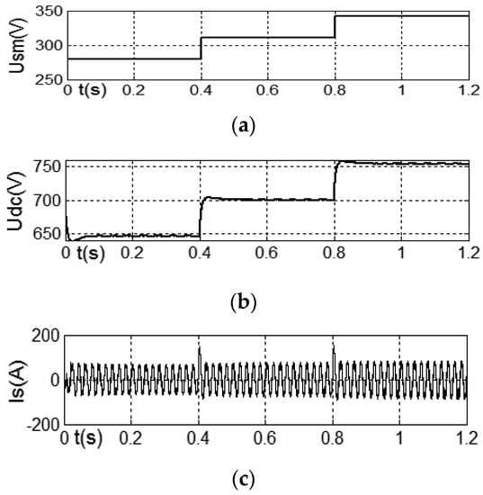
Figure 8.
Waveforms with the droop controller. (a) Peak value of the grid phase voltage Usm; (b) DC-link voltage Udc; (c) Source current Is after compensation.
3.2. Experimental Results and Analysis
Experiments were carried out in the developed APF system (66 kVA) to verify the correctness and feasibility of the above analysis. The double closed-loop PI control algorithm is implemented by a piece of microcontroller, the TMS320F28335 from TI. The type of IGBT is the FF300R12. The voltage and current ratings of the IGBT are 1200 V and 300 A, respectively. Table 1 shows the main parameters of the shunt APF system. The harmonic load is a three-phase uncontrolled rectifier with a resistive load (10.8 Ω), and the reactor internal resistance is 0.5 Ω.

Table 1.
Main parameters of the APF system.
Figure 9 shows the experimental waveforms using a direct source current detection control scheme. Figure 9a shows the three-phase uncontrolled rectified load current waveform. Figure 9b shows the source current waveform after APF compensation. Figure 9c shows the harmonic current waveform.
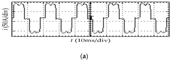
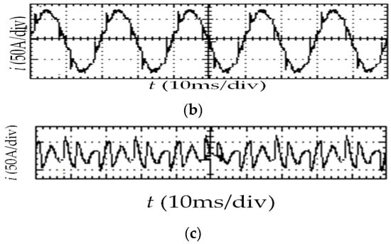
Figure 9.
Waveforms of load, source and harmonic current. (a) Three-phase uncontrolled rectifier load current waveform; (b) Source current waveform after APF compensation; (c) Harmonic current waveform.
Figure 10 shows the spectrum of the grid side current before and after the APF application. Figure 10a shows the load current THD spectrum before the APF application. Figure 10b shows the system current THD spectrum after APF compensation.
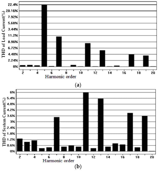
Figure 10.
Magnitude spectrum of load current and source current waveforms. (a)Three-phase uncontrolled rectified load current waveform spectrum before the APF application; (b)Three-phase system current waveform spectrum after the APF application.
As seen in Figure 9 and Figure 10, the system source current after APF compensation is close to an ideal sine wave, the THD of the system current harmonic distortion decreases from 28.5% to 15%, the THD of the 5th harmonic decreases from 22.4% to less than 0.6%, the THD of the 7th harmonic decreases from 11% to less than 3.6%, the THD of the 11th harmonic decreases from 8.9% to 6%, the THD of the 13th harmonic decreases from 5.8% to about 5.4%, and other higher harmonics also declined to varying degrees. However, due to the limitation of the bandwidth range of the PI controller, the system current waveform spikes at certain fixed points, which can be eliminated by improving the controller. In short, based on the source current control scheme, using the conventional PI controller can realize the non-static error suppression of the load current harmonics and achieve a good harmonic suppression effect.
The dynamic performance of the APF is verified based on the source circuit control and the observed response of the system by sudden addition and unloading experiments for harmonic loads. Figure 11 and Figure 12 show that the response speed of the controller is fast, and the APF can respond quickly to sudden changes in instruction, which can significantly reduce the active power emitted or absorbed by the load change. However, half-cycle command distortion occurs due to the existence of a low-pass filter in the harmonic extraction section.
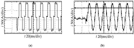
Figure 11.
Load and source current waveforms during loading. (a) The load current waveform during load on; (b) The source current waveform during load on.
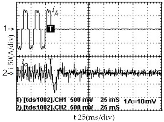
Figure 12.
Load and harmonic current waveforms during load off.
The relationship between the compensation performance of the APF system and the DC-link voltages is then verified. Meanwhile, the relationship between the power losses of the APF system and the DC-link voltages is also verified. In the case of grid voltage fluctuation, the system performance before and after DC-link voltage control by the droop regulator is compared and analyzed. The room test temperature is 25 degrees Celsius, and the active power on the APF output side is measured by a power quality analyzer. The APF output current is the APF rated current, or the output current is not less than 90% of rated current. It should be noted that harmonic loads were running for at least half an hour before the application of the APF, and the test data were recorded after an hour of stable operation of the APF. The final data obtained from the test is the average value after multiple measurements. The type of current transducer is DHR-100-C10. The rated current of transducer IPN is 100 A. Both the linearity error and accuracy of the transducer are less than 1% IPN. Seven sets of experimental tests are conducted using different grid voltage and DC-link voltage Based on the experimental results, a performance analysis table for the APF system in different situations is listed. In Table 2, Us is the effective value of the grid phase voltage, Il is the effective value of the source current, THDI is the distortion rate of the source current, and Ploss is the active power loss of the APF system.
Table 2.
Analysis of compensation performance and power losses on APF.
As shown in Table 2, when the grid voltage is constant, the DC-link voltage is increased, the harmonic current distortion rate is reduced, and the power loss of the APF system is increased. After using the droop controller, when the grid voltage rises, the APF compensation capability is improved by increasing the DC-link voltage. When the source voltage is reduced, the given value of the DC-link voltage is decreased so that the system loss is reduced.
4. Conclusions
Based on a traditional control method used by shunt APFs, this paper proposes a control scheme based on the source current. The detection of harmonics and reactive currents is omitted, and the double closed-loop cascade control structure and the non-static error control law of the ordinary PI controller are retained, which improves the dynamic performance and control reliability of the system. In addition, the APF power loss and compensation performance increase with the increase of the DC-link voltage and decrease with the decrease of the DC-link voltage. When the actual grid voltage fluctuates, the droop regulator is used to control the DC-link voltage reference value, which can realize the comprehensive optimization of APF power loss and compensation performance.
Author Contributions
Conceptualization, X.C.; Methodology, X.C.; Validation, K.D.; Visualization, X.W.; Writing—original draft, X.W.; Writing—review and editing, K.D. and X.W. All authors have read and agreed to the published version of the manuscript.
Funding
This research received no external funding.
Conflicts of Interest
The authors declare that there is no conflict of interests regarding the publication of this paper.
References
- Akagi, H. Active Harmonic Filters. Proc. IEEE 2005, 93, 2128. [Google Scholar] [CrossRef]
- Feng, Y.Q.; Wang, X.; Zhou, L.D.; Zheng, Y.H. Application of Neural Network Adaptive PI Controller in Active Power Filter. Power Syst. Prot. Control 2011, 39, 74. [Google Scholar]
- Jiang, W.D.; Wang, L.; Ma, W.C. Control Method Based on Current Tracking Error Compensation of Deadbeat Control for a Three-phase Active Power Filter. Proc. CSEE 2016, 36, 5605. [Google Scholar]
- Zhao, X.T.; Qiu, Z.F.; Yu, J.R.; Li, Y.G.; Gui, W.H. Research of Refined Compensation Method on Shunt Active Power Filter. Power Syst. Technol. 2018, 42, 1290. [Google Scholar]
- Huang, H.H.; Wei, Y.C.; Wang, H.X.; Chen, Y. The Application of Specific Harmonic Filtering and Phase Locked in Active Power Filter. Electr. Power Autom. Equip. 2019, 39, 1. [Google Scholar]
- Huang, J.M.; Li, X.M. Detection of Harmonic in Power System Based on Short-time Fourier Transform and Spectral Kurtosis. Power Syst. Prot. Control 2017, 45, 43. [Google Scholar]
- Wang, H.C.; Wang, L.; Sheng, X.; Yang, X. New Harmonic Detection Method Based on LMS Algorithm of Improved Adaptive Gain. Power Syst. Prot. Control 2016, 44, 42. [Google Scholar]
- Wang, G.Z. An Investigation on the Unnecessary of Harmonic and Reactive Current Detection for Active Power Filters (part I). Trans. China Electrotech. Soc. 2007, 22, 137. [Google Scholar]
- Wang, G.Z. An Investigation on the Unnecessary of Harmonic and Reactive Current Detection for Active Power Filters (part II) Simulation and Experiment. Trans. China Electrotech. Soc. 2007, 22, 132. [Google Scholar]
- Xu, Z.D.; Liu, J.; Huang, L.; Dai, J. Design of Adaptive Fuzzy Controller on Shunt Active Power Filter. J. Harbin Univ. Sci. Technol. 2012, 2, 63. [Google Scholar]
- Fei, J.T.; Ma, K.Q.; Zhang, S.L.; Yan, W.; Yuan, Z. Adaptive Current Control with PI-Fuzzy Compound Controller for Shunt Active Power Filter. Math. Probl. Eng. 2013, 47, 343. [Google Scholar] [CrossRef]
- Chen, X.C.; Chang, X.R.; Yao, P.; Wu, C. Research on Sliding Mode Control of DC-side Voltage of DSTATCOM. Power Electron. Technol. 2015, 49, 79. [Google Scholar]
- Li, H.J.; Wang, J.; Sun, Z.; Wang, T. A Droop Controller to Improve the Sharing Accuracy of Reactive Power. Electr. Drive 2019, 49, 69. [Google Scholar]
- Xu, S.; Fei, S.M.; Zhao, J.F. Harmonic Current Frequency Dividing Control Strategy Based on Synchronous Rotating Frame. Trans. China Electrotech. Soc. 2016, 31, 154. [Google Scholar]
- Xia, W.H.; Yan, Z.F.; Li, Z.X.; Zhang, X. Research on DC Voltage Balance Control Strategy of APF Based on Improved Adaptive Algorithm. Electr. Drive 2016, 46, 42. [Google Scholar]
- Wang, Y.F.; Wang, X.; Liu, G.H.; Li, G.H. APF DC Voltage Control Strategy Based on Adaptive Fuzzy Droop Control. High Volt. Appar. 2017, 53, 39. [Google Scholar]
- Hoon, Y.; Radzi, M.A.M.; Hassan, M.K.; Mailah, N.F. Neutral-point Voltage Deviation Control for Three-level Inverter-based Shunt Active Power Filter with Fuzzy-based Dwell Time Allocation. IET Power Electron 2017, 10, 429. [Google Scholar] [CrossRef]
- Li, Z.C.; Zhao, G.J.; Liu, G.H.; Xu, D.Z. Compound Control Method for DC-link Voltage of Active Power Filter. Power Electron. 2019, 53, 103. [Google Scholar]
- Zhao, G.P.; Liu, J.J.; Yang, X.; Wang, Z. Analysis and Specification of DC Side Voltage in Parallel Active Power Filter Regarding Compensation Characteristics of Generators. In Proceedings of the Power Electronics Specialists Conference 2008 IEEE, Rhodes, Greece, 15–19 June 2008; Volume 7, p. 3495. [Google Scholar]
- Chaoui, A.; Gaubert, J.-P.; Krim, F.; Rambault, L. On the Design of Shunt Active Filter for Improving Power Quality. In Proceedings of the IEEE International Symposium Industrial Electronics, Cambridge, UK, 30 June–2 July 2008. [Google Scholar]
- Rong, P.X.; Liu, Z.Y.; Yang, C.W. Harmonic Detection Simulation Design of Active Power Filter. J. Harbin Univ. Sci. Technol. 2015, 1, 66. [Google Scholar]
- Akagi, H.; Kanazawa, Y.; Nabae, A. Instantaneous Reactive Power Compensators Comprising Switching Devices Without Energy Storage Components. IEEE Trans. Ind. Appl. 1984, 20, 625. [Google Scholar] [CrossRef]
- Wei, X.L.; Dai, K.; Xie, B.; Kang, Y.; Peng, H.L. Control Scheme for Three-phase Three-wire Shunt Active Power Filter with Unbalanced Loads. Proc. Chin. Soc. Electr. Eng. 2008, 28, 64. [Google Scholar]
- Xie, B.; Dai, K.; Zhang, S.Q.; Kang, Y. Optimization Control of DC-link Voltage for Shunt Active Power Filter. Proc. Chin. Soc. Electr. Eng. 2011, 31, 23. [Google Scholar]
- Zhang, J.H.; Wang, J.; Chen, X.Y.; Mo, Y.P.; Xin, F.L. Study on LVRT Control Strategy of Eliminating Harmonic Current. J. Harbin Univ. Sci. Technol. 2012, 1, 20. [Google Scholar]
- Li, W.J.; Wu, T.Q.; Sheng, Y. Unified Positive and Negative Order Detection Method for Single Harmonic of Active Power Filter. J. Harbin Univ. Sci. Technol. 2016, 3, 13. [Google Scholar]
- Mthombeni, L.T.; Pillay, P.; Singampalli, N.A. Lamination Core Loss Measurements in Machines Operating with PWM or Nonsinusoidal Excitation. In Proceedings of the Electric Machines and Drives Conference, IEMDC, Madison, WI, USA, 1–4 June 2003; Volume 2, p. 742. [Google Scholar]
- Li, J.G.; Zou, J.B.; Tan, J.B. Losses Calculation of IGBT Module and Heat Dissipation System Design of Inverters. Power Electron. 2009, 24, 159. [Google Scholar]
- Tan, F.D.; Vollin, J.T.; Cuk, S.M. A Practical Approach for Magnetic Core-loss Characterization. IEEE Trans. Power Electron. 1995, 10, 356. [Google Scholar]
- Li, C.H.; Li, F.; Qu, J.S. The characteristics of Space Vector Pulse Width Modulation (SVPWM) Technique and Its Optimized Methods. J. Shandong Univ. (Eng. Sci.) 2005, 35, 27. [Google Scholar]
- Wei, X.L.; Dai, K.; Fang, X.; Kang, Y. Performance Analysis and Improvement of Output for Three Phase Shunt Active Power Filter. Proc. Chin. Soc. Electr. Eng. 2007, 27, 113. [Google Scholar]
- Zhang, Z.Y. Oscillation Index Method in Engineering Design of Automatic Control System. Electr. Eng. 1989, 1, 28. [Google Scholar]
© 2020 by the authors. Licensee MDPI, Basel, Switzerland. This article is an open access article distributed under the terms and conditions of the Creative Commons Attribution (CC BY) license (http://creativecommons.org/licenses/by/4.0/).