Article

Short-Circuit Fault Current Calculation Method for the Multi-Terminal DC Grid Considering the DC Circuit Breaker

1
Institute of Electrical Engineering, Chinese Academy of Sciences, Beijing 100190, China
2
School of Electronic, Electrical and Communication Engineering, University of Chinese Academy of Sciences, Beijing 100049, China
3
China Energy Engineering Group, Jiangsu Power Design Institute Co., LTD, Nanjing 211102, China
*
Author to whom correspondence should be addressed.
Energies 2020, 13(6), 1347; https://doi.org/10.3390/en13061347
Submission received: 6 February 2020 / Revised: 6 March 2020 / Accepted: 12 March 2020 / Published: 13 March 2020
(This article belongs to the Section F: Electrical Engineering)

Abstract

:
The analysis and calculation of the short-circuit fault current in the DC grid is of great significance to the design and configuration of the converter station and DC circuit breaker parameters. The existing flexible DC system not only includes the modular multilevel converter (MMC) converter, but also needs power equipment such as the fault current limiter and DC circuit breaker. Therefore, the system modeling and short circuit calculation of the multi-terminal DC system after adding the DC circuit breaker are also of great significance for the design of DC power system parameters and the grid troubleshooting ability. In this paper, firstly, the parameters of the four-terminal DC system of the modular multilevel converter (MMC) are simplified, and the analytical solution of the short circuit fault current of the multi-terminal DC system is given. Then, the external characteristics of the cascaded hybrid DC circuit breaker are modeled. Based on the equivalent circuit of the fault current in different stages, the short circuit calculation method of four-terminal MMC system with DC circuit breaker is obtained. This method can effectively describe the overall trend of fault current and provide the basis for the configuration of DC line protection settings and DC circuit breaker related parameters.

Graphical Abstract

1. Introduction

In recent years, as one of the effective technical means to solve the new energy grid-connection and accommodation, flexible DC transmission technology has become a hot topic of academic research [1,2,3]. Multi-terminal flexible DC transmission can meet the demand of multi power supply and receiving, and effectively reduce the number of converters. The half bridge submodule modular multilevel converter (MMC) topology is often used in the existing flexible DC grid projects. In the DC grid, the short circuit fault is a serious problem, among which the pole-to-pole short circuit is the most serious fault type [4,5,6,7]. When the DC side of the converter with MMC topology has a short circuit fault, the submodule capacitor will discharge through the fault point, which will cause a great impact on the MMC converter and other DC system equipment, seriously endangering the safe and stable operation of the DC system. Therefore, it is very important for the safe and stable operation of flexible DC transmission to install DC fault current limiter (FCL) and direct current circuit breaker (DCCB) on the DC side to realize the fast current limiting and blocking of the DC fault [2].
When designing the parameters of the fault protection system, it is required that the high-voltage DC circuit breaker cut offs the short-circuit current under the most extreme fault of the DC system [8,9,10,11]. Therefore, it is necessary to complete the analysis of the short-circuit fault characteristics of the DC system including the DC circuit breaker, realize the parameter capacity matching of the converter, the FCL and the DCCB, and improve the reliability and economy of the system operation. At present, the types of DC circuit breakers studied mainly include the mechanical type, solid-state type, and hybrid type. Since the hybrid DCCB has the advantages of low on-state loss of the mechanical circuit breaker and fast breaking of the solid-state circuit breaker, hybrid DCCB has become the main research direction of the circuit breaker [1,2,3]. Therefore, the calculation and analysis of the short-circuit fault current in this paper is based on hybrid DCCB.
At present, most of the researches on DC circuit breakers focus on the new topology design [12,13,14,15], breaking characteristics [16,17,18,19,20], and suppression mechanism [21,22,23,24]. Some other researchers focus on the short-circuit current analysis. In the MMC-HVDC system, [25] deduced the analytic equation for single terminal MMC pole-to-pole fault current calculation. In addition, the single terminal MMC arm fault current before and after the converter blocked during a pole-to-pole fault was analyzed in [25]. However, the detailed DC-side fault current calculation of a DC grid has to solve the electrical coupling problems because all the converter capacitors discharging at the same time in a meshed network. The DC-side fault analysis and characteristics of two-level VSC and MMC based multi-terminal DC systems are proposed in [26,27,28] respectively. However, the proposed solution for obtaining the DC grid fault currents is by electromagnetic transient (EMT) simulations. However, the EMT models of the entire DC grid are usually quite time consuming especially for the grid with multiple MMC converters. Meanwhile the DCCB model is not considered in the whole calculation and analysis process. Li, C [29] deduces the mathematical modeling of the multi-terminal flexible DC system based on MMC, and the current analytical formula of the multi-terminal flexible DC system under the pole-to-pole short circuit fault is derived. Although the transient stability analysis of the DC system with DCCB under the short circuit fault is mentioned in the simulation, the detailed mathematical model and combined calculation process of the DC circuit breaker are not given.
The equivalent models of different transfer branches of hybrid DC circuit breakers are quite different in DC lines, so it is necessary to combine the external characteristics of DCCB into the short-circuit fault analysis of multi-terminal DC systems. There are few short-circuit fault analysis that takes the external characteristics of DC circuit breakers into account in the multi-terminal DC system. Even if some scholars will add the circuit breaker model to the short circuit calculation process, they only equivalent it to a simple switch model, which is no longer applicable to the hybrid DC circuit breaker, which has undergone switching of multiple transfer branches during the breaking process.
In order to solve the above problems, this paper proposes a short circuit calculation and analysis method of four-terminal flexible DC system including cascaded full bridge hybrid DCCB, which provides theoretical basis for the design of DC system protection control strategy and the parameter setting of DCCB, DC FCL, and other related protection equipment.
Firstly, the commutating process of cascaded full bridge hybrid DC circuit breaker is analyzed, and the equivalent circuit of different transfer branches is obtained. Then, the mathematical model of MMC-HVDC system with DCCB is established. Aiming at the different time sequence equivalent model of DC circuit breaker, the corresponding matrix parameter equation of the short-circuit process is given, and the calculation method of the short-circuit current of the whole process system considering the DC circuit breaker is proposed. By comparing the transient simulation and short circuit calculation results of the four-terminal DC system, the correctness of the whole process short circuit calculation method is verified. On this basis, according to the short circuit calculation equation, the configuration method of the DC circuit breaker parameters is given, which can be further extended to multi-terminal DC system.

2. Equivalent Circuit of Cascade Full Bridge Hybrid DCCB

The cascaded full bridge hybrid DCCB is proposed by the State Grid Corporation of China [3]. Fault transfer branch realizes the voltage level improvement through the series connection of full bridge submodules, avoiding the problem of voltage sharing of switching devices caused by the direct series connection of IGBTs. Therefore, this paper takes this DC circuit breaker topology as an example to calculate and analyze the short-circuit of four-terminal DC grid, and other hybrid DCCB topologies are also applicable. 
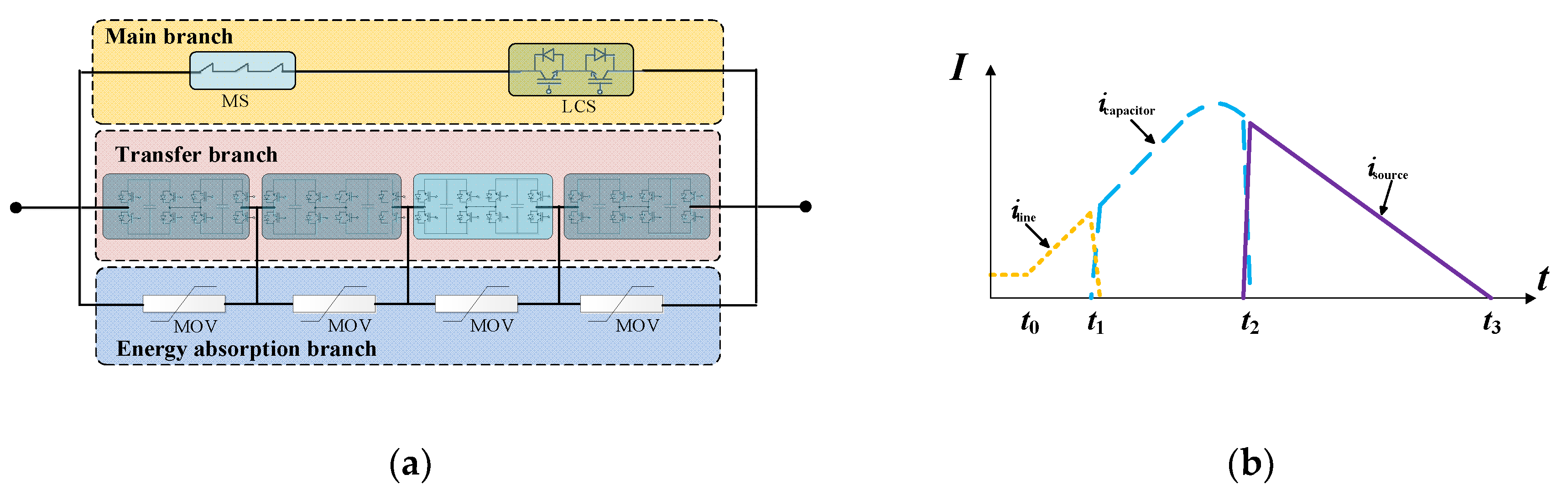
Figure 1a,b are the topological structure and current breaking process diagram of cascaded full bridge hybrid DCCB respectively.
In 
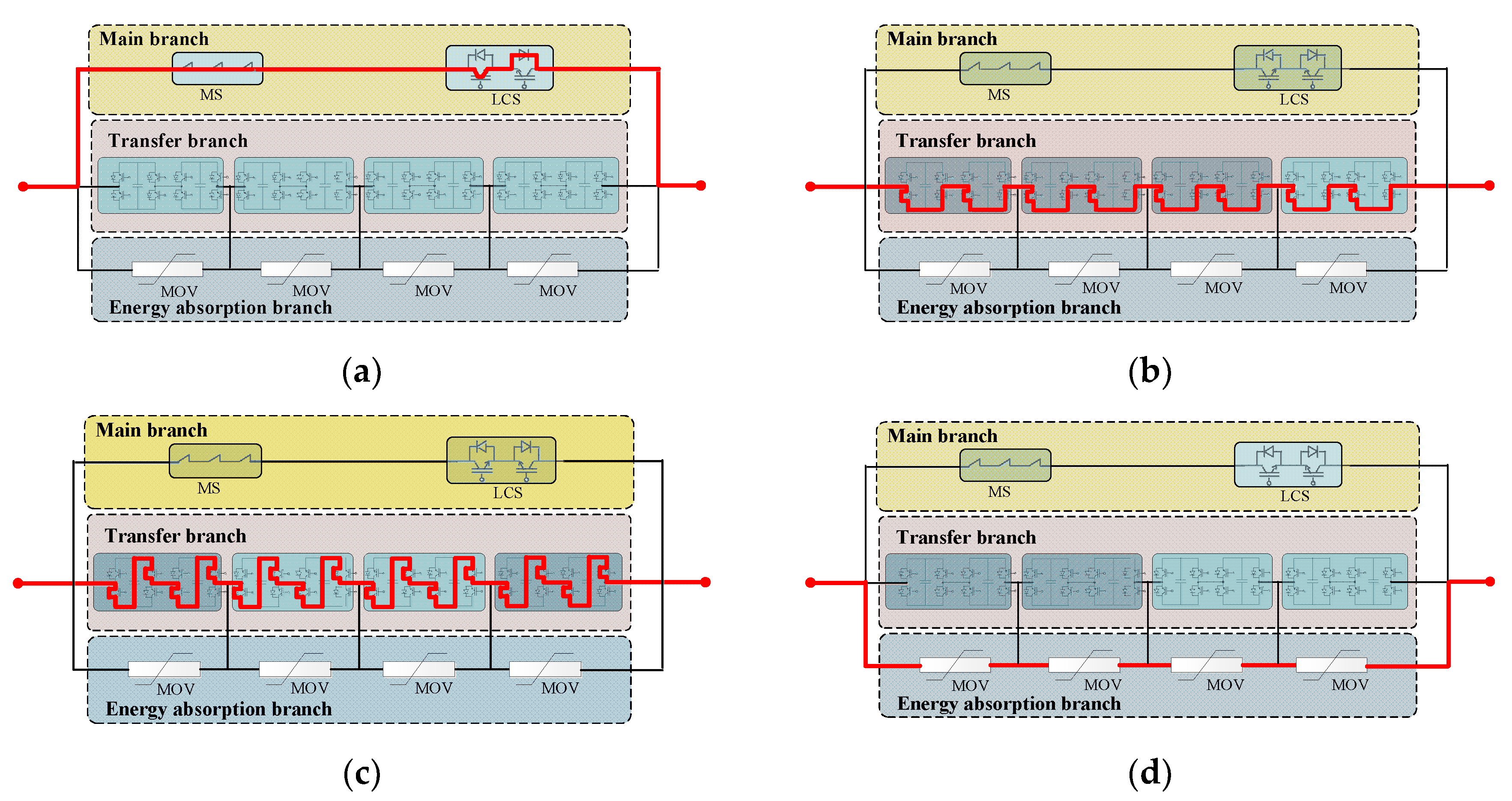
Figure 1a, the current flows through the main branch (MB), including the mechanical switch (MS) and load current switch (LCS) under the rated working condition. At this time, the main branch is equivalent to the impedance accessing line, as shown in Figure 2a (the impedance value is very small and can be ignored). At t0 moment, when the line occurs short-circuit fault, the DCCB remains in the working state as shown in Figure 2a before receiving the breaking command. After receiving the breaking command, the two down IGBTs of full bridge submodule of the transfer branch are closed, the load current switch is open, and the fault current is transferred to the transfer branch (TB), as shown in Figure 2b. At this time, the circuit breaker is still equivalent to the impedance (negligible). At t1 time, when the mechanical switch of the main branch is completely disconnected, the two down IGBTs of the full bridge submodule of the transfer branch is disconnected, and the fault current is the charging of the submodule capacitor. At this time, the circuit breaker is equivalent to the capacitor (the initial voltage of the capacitor is zero), as shown in Figure 2c. At t2 time, when the capacitor voltage of the submodule reaches the clamping voltage of the metal oxide varistor (MOV), the fault current is transferred to the energy absorption branch (EAB), as shown in Figure 2d. The energy absorption region should be in the linear region in the metal oxide varistor I-V characteristic curve [30], which means the energy absorption circuit can be equivalent to a DC voltage source connected in series to the circuit during this time. Therefore, in Figure 1b, t0–t1 time, the circuit breaker was equivalent to the impedance. At t1– t2 time, the circuit breaker was equivalent to the capacitor. At t2–t3 time, the circuit breaker was equivalent to the DC voltage source.

3. Equivalent Circuit of the Four-Terminal Bipole MMC DC System

This paper mainly analyzed the pole-to-pole short-circuit fault, because the pole-to-pole short-circuit fault is the most serious fault type of the DC side in the multi-terminal DC transmission system, and it is also the key factor to consider the breaking capacity of DCCB [28]. 
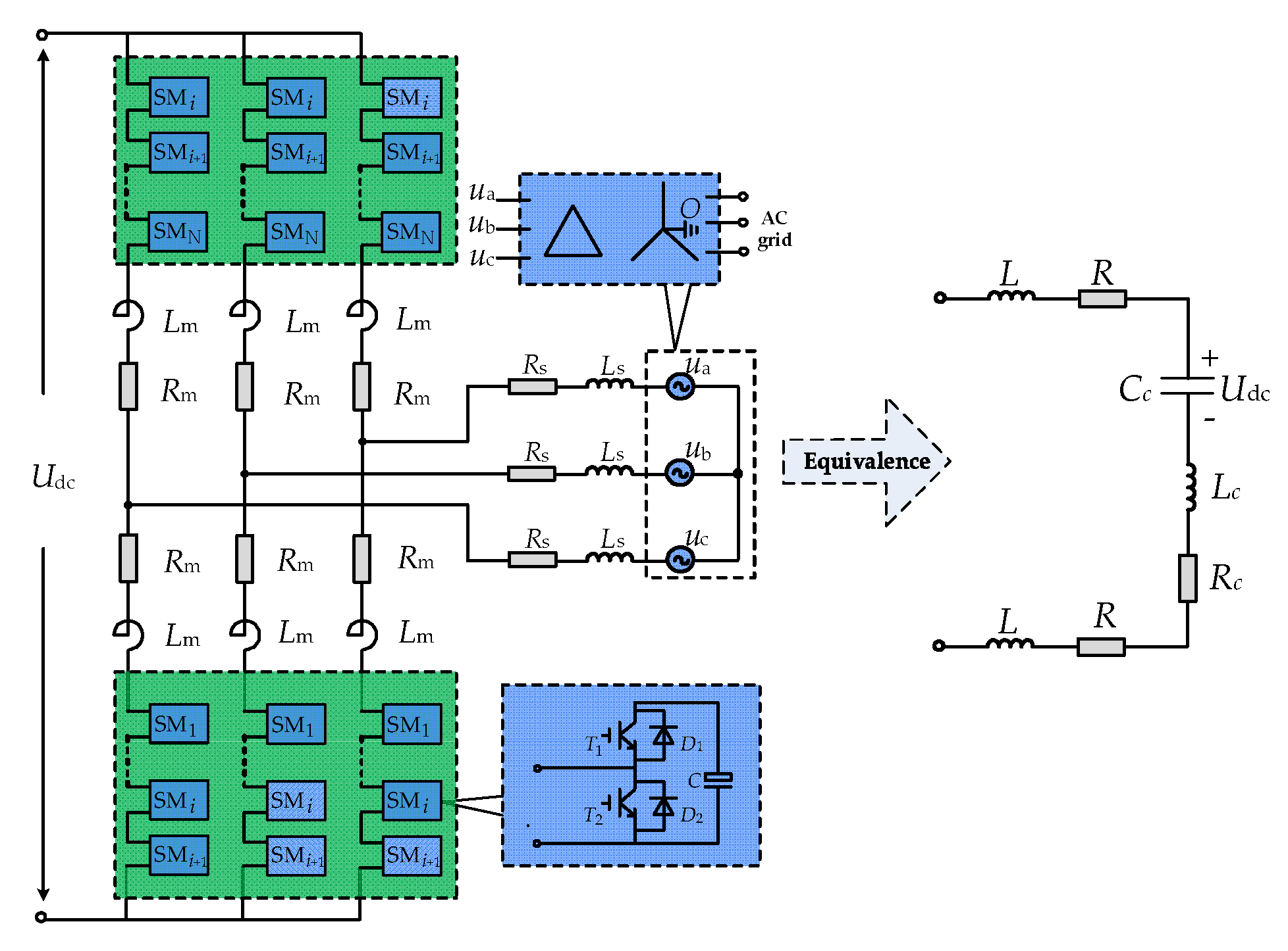
Figure 3 shows the basic structure of the typical three-phase MMC and half bridge submodule model. The converter of each pole is composed of three-phase six arms, each arm is composed of N submodules (SM) and an arm inductor Lm in series. If Rc, Lc, and Cc are used to represent the equivalent resistor, inductor and capacitor of MMC converter, the equivalent discharging circuit of the MMC converter as shown in Figure 3 can be obtained.
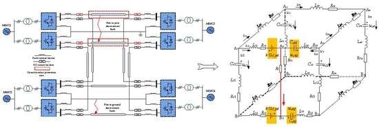
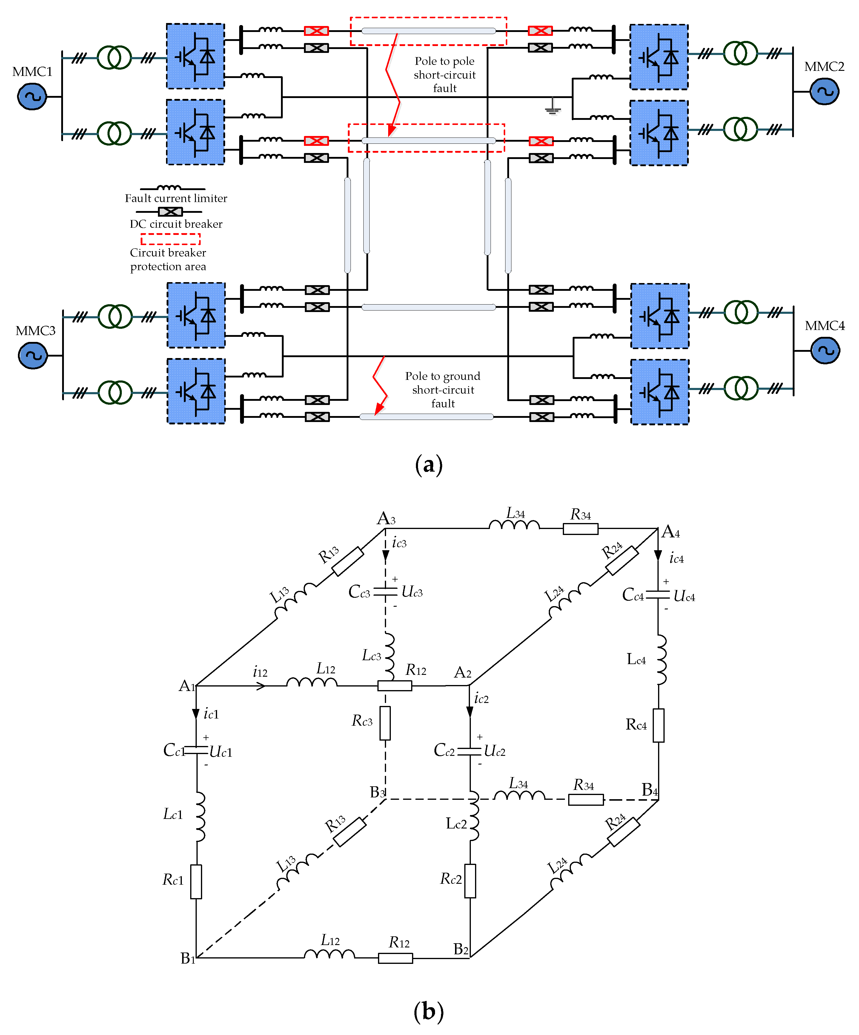
The schematic diagram of the four-terminal bipole MMC DC system with DCCB is shown in Figure 4a. The four-terminal ring topology structure was adopted, and two rectifier stations and two inverter stations were set in total. The DC side was the bipole structure.
In order to limit the rising rate of the fault current, a DC FCL is needed on the DC side. For the four-terminal DC grid, two configuration schemes of DC FCL are often used, which are centralized scheme and decentralized scheme [4,6,23]. The decentralized scheme is more conducive to limit the speed of fault expansion, and is suitable for different fault positions in the line. Therefore, in Figure 4a, the decentralized FCL was adopted, and both ends of each line were equipped with current limiting inductors. According to the four-terminal MMC system circuit in Figure 4a and the Figure 3 MMC discharge model, the four-terminal ring network equivalent model with the DC circuit breaker was obtained, as shown in Figure 4b.

4. Short Circuit Current Calculation of the Four-Terminal MMC System with DCCB

In order to analyze the influence of DCCB on the whole system, the equivalent model of a different breaking process of DCCB should be combined. DC circuit breakers are installed at both ends of each line. As shown in Figure 4a, both positive and negative poles of MMC1 and MMC2 are installed at the same time. When a short-circuit fault occurs on one side of the system, the circuit breakers on both sides of the fault point start to break at the same time after receiving the short-circuit fault command, and the positive and negative circuit breakers close to the same converter have the same action process. Due to the line impedance, the breaking action of the circuit breakers on both sides of the fault point is not completely consistent. Taking the DCCB between the A1A2 line and B1B2 line in Figure 4b as an example, the short circuit point is close to the A1B1, and the short circuit calculation model can be theoretically divided into the following 8 types (CB1 is the left circuit breaker at the fault point, which is the near circuit breaker; CB2 is the right circuit breaker at the fault point, which is the remote circuit breaker.), as shown in Table 1.
Note: the state of O indicates that the circuit breaker works at t0t1 in Figure 1b, and the impedance is the equivalent of the circuit breaker; the state of C indicates that the circuit breaker works at t1t2 in Figure 1b, and the capacitor is the equivalent of the circuit breaker; the state of S indicates that the circuit breaker works at t2t3 in Figure 1b, and the DC source is the equivalent of the circuit breaker; the state of B indicates that the circuit breaker is completely disconnected and the current drops to zero.
This paper considered that when the fault occurs, the breakers at both ends of the fault line would receive the breaking command at the same time and start to break. It should be noted that the breaking command is from the fault detection algorithm, and the fault detection algorithm depends on real-time monitoring. The paper’s short-circuit current calculation could be used as a reference value for the fault detection algorithm. By means of adjusting the current protecting value of the fault detection algorithm, the breaking command can be obtained rapidly.
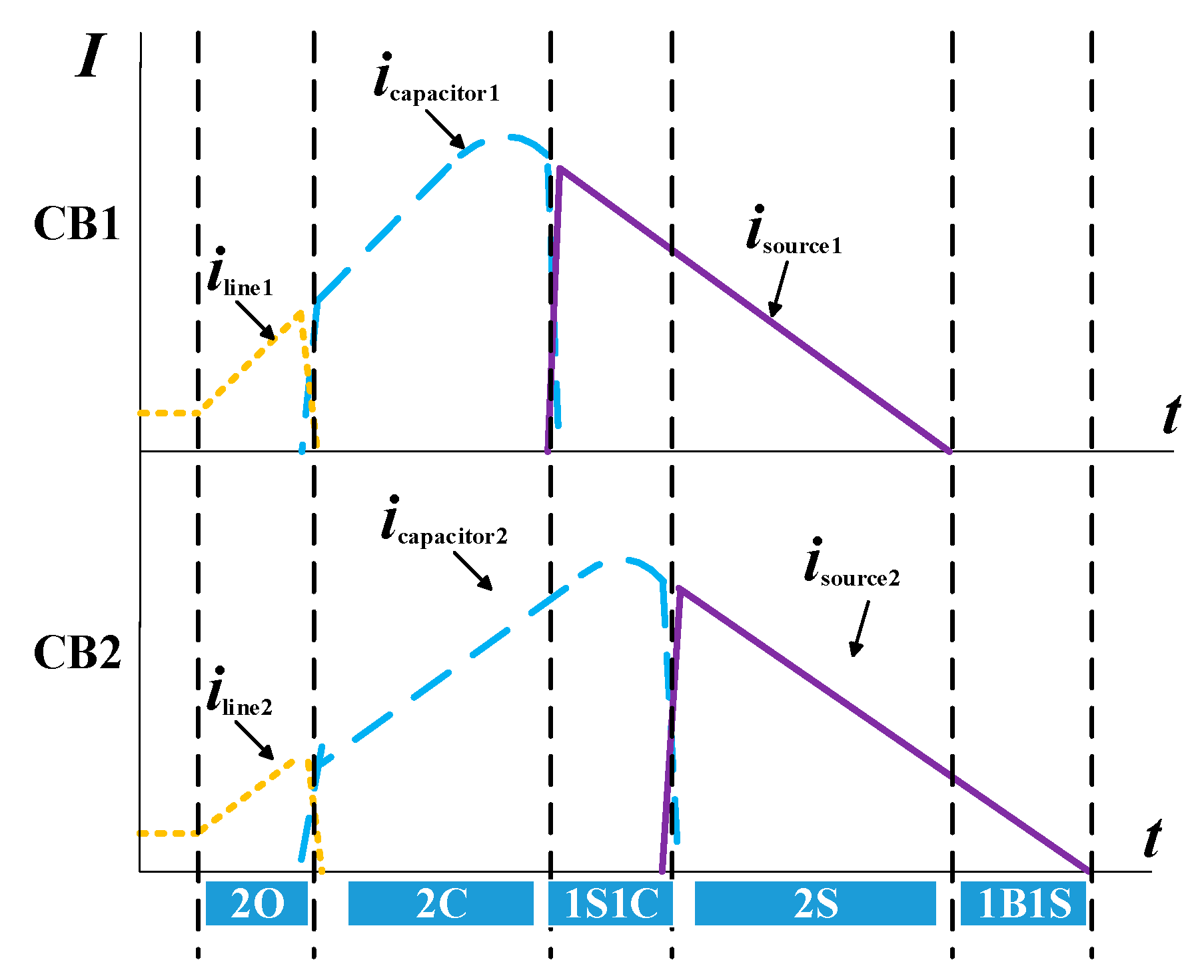
In the normal operation of the four-terminal flexible DC system, the equivalent circuit of each DC line is in the stage of 2O. When the system detects the fault and sends the breaking command to the DC circuit breakers at both ends, CB1 and CB2 start to break at the same time, and the fault current is transferred from the main branch to the submodule switching device branch at the same time, that is, from Figure 2a to Figure 2b. At this time, the system equivalent model is still in the state of 2O. Since CB1 and CB2 wait the same time for the mechanical switch to break completely, CB1 and CB2 switch to the capacitor branch of the submodule at the same time, that is to say, they switch from Figure 2b to Figure 2c. At this time, the system equivalent model is still 2C. Due to the small impedance between CB1 and the fault point, the current rise rate is high. Therefore, CB1 takes the lead in transferring the current to the energy absorption branch under the same clamping voltage of the MOV. At this time, the system equivalent model is 1S1C. When the capacitor of CB2 submodule reaches the clamping voltage of arrester, the current of two circuit breakers works in the energy absorption branch, and the system equivalent model is the state of 2S. Compared with the remote circuit breaker CB2, the near circuit breaker CB1 takes the lead in the stage of an equivalent DC source, and then completes the breaking of the fault current ahead of time. At this time, the system equivalent model is 1B1S. The fault isolation of MMC1-MMC2 is realized with the fault breaking of circuit breakers at both ends. Then the equivalent circuit of the four-terminal system after the near MMC1 fault has gone through five stages: 2O-2C-1S1C-2S-1B1S. The simplified diagram is shown in Figure 5.
In the following, equivalent circuit modeling and short circuit calculation analysis were carried out for the above five cases respectively.

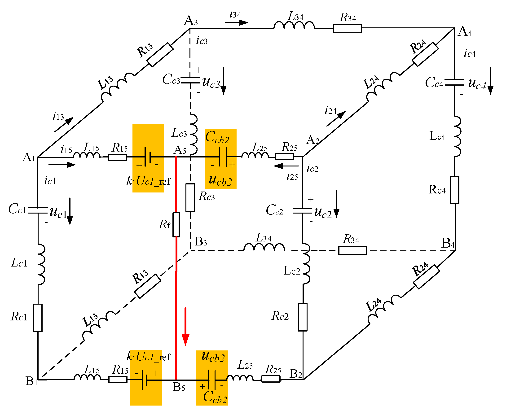
4.1. No Action of CB1 and CB2 (Step:2O)
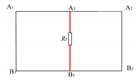
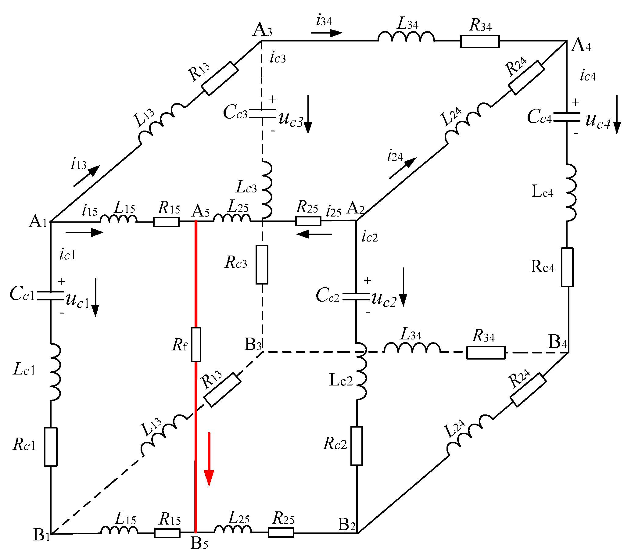
Assuming that at t0, the pole-to-pole short circuit fault occurs at A5 between A1 and A2 converter stations, the original A1A2 branch is divided into two parts. At this time, the circuit breaker has not yet operated, and the equivalent circuit of the system pole-to-pole fault is shown in Figure 6.
After the pole-to-pole short-circuit fault occurs in the system, the four side loops of the original model are divided into five loops by the short-circuit fault branch A5B5. The KVL equation can be obtained:
{ u c 1 = R c 1 i c 1 L c 1 d i c 1 d t + 2 R 15 i 15 + 2 L 15 d i 15 d t + ( i 15 + i 25 ) R f u c 2 = R c 2 i c 2 L c 2 d i c 2 d t + 2 R 25 i 25 + 2 L 25 d i 25 d t + ( i 15 + i 25 ) R f u c 1 u c 3 = R c 1 i c 1 L c 1 d i c 1 d t + 2 R 13 i 13 + 2 L 13 d i 13 d t + i c 3 R c 3 + L c 3 d i c 3 d t u c 3 u c 4 = R c 3 i c 3 L c 3 d i c 3 d t + 2 R 34 i 34 + 2 L 34 d i 34 d t + i c 4 R c 4 + L c 4 d i c 4 d t u c 2 u c 4 = R c 2 i c 2 L c 2 d i c 2 d t + 2 R 24 i 24 + 2 L 24 d i 24 d t + i c 4 R c 4 + L c 4 d i c 4 d t
According to KCL, each converter currents are obtained:
{ i c 1 = i 13 i 15 i c 2 = i 24 i 25 i c 3 = i 13 i 34 i c 4 = i 34 + i 24
Combining (2) to (1) yields:
{ u c 1 = R c 1 i 13 + ( R c 1 + 2 R 15 + R f ) i 15 + R f i 25 + L c 1 d i 13 d t + ( L c 1 + 2 L 15 ) d i 15 d t u c 2 = R f i 15 + R c 2 i 24 + ( R c 2 + 2 R 25 + R f ) i 25 + L c 2 d i 24 d t + ( L c 2 + 2 L 25 ) d i 25 d t u c 1 u c 3 = ( R c 1 + 2 R 13 + R c 3 ) i 13 + R c 1 i 15 R c 3 i 34 + ( L c 1 + 2 L 13 + L c 3 ) d i 13 d t + L c 1 d i 15 d t L c 3 d i 34 d t u c 3 u c 4 = R c 3 i 13 + R c 4 i 24 + ( R c 3 + 2 R 34 + R c 4 ) i 34 L c 3 d i 13 d t + L c 4 d i 24 d t + ( L c 3 + 2 L 34 + L c 4 ) d i 34 d t u c 2 u c 4 = ( R c 2 + 2 R 24 + R c 4 ) i 24 + R c 2 i 25 + R c 4 i 34 + ( L c 2 + 2 L 24 + L c 4 ) d i 24 d t + L c 2 d i 25 d t + L c 4 d i 34 d t
Combing (3) to (4) yields:
i 0 = [ i 15 i 25 i 13 i 34 i 24 ] T u 0 = [ u c 1 u c 2 u c 3 u c 4 ] T i c 0 = [ i c 1 i c 2 i c 3 i c 4 ] T
Therefore, the matrix shown in (3) can be written as:
A 0 · u 0 = R 0 · i 0 + L 0 · i 0 · i c 0 = A 0 T · i 0
where, A0 is the voltage correlation matrix of converter, R0 is the circuit resistance matrix and L0 is the circuit inductor matrix. The matrix expressions are:
A 0 = [ 1 0 0 1 0 0 0 0 1 0 1 0 0 0 1 1 0 1 0 1 ]
R 0 = [ R c 1 + 2 R 15 + R f R f R c 1 0 0 R f R c 2 + 2 R 25 + R f 0 0 R c 2 R c 1 0 R c 1 + 2 R 13 + R c 3 R c 3 0 0 0 R c 3 R c 3 + 2 R 34 + R c 4 R c 4 0 R c 2 0 R c 4 R c 2 + 2 R 24 + R c 4 ]
L 0 = [ L c 1 + 2 L 15 0 L c 1 0 0 0 L c 2 + 2 L 25 0 0 L c 2 L c 1 0 L c 1 + 2 L 13 + L c 3 L c 3 0 0 0 L c 3 L c 3 + 2 L 34 + L c 4 L c 4 0 L c 2 0 L c 4 L c 2 + 2 L 24 + L c 4 ]
So far, the parameter matrixes of the four-terminal ring network MMC equivalent mathematical model to calculate the short-circuit current under the pole-to-pole short-circuit fault are shown. According to Equation (5) and MMC capacitor differential equation, the final system simultaneous differential equation is obtained:
{ A 0 · u 0 = R 0 · i 0 + L 0 · i 0 · u 0 · = C · A T · i 0
where C is the equivalent capacitor matrix of each converter as:
C = d i a g [ 1 C c 1 1 C c 2 1 C c 3 1 C c 4 ]
As shown in Figure 1b, this equivalent circuit duration is t0t1. According to the rated operation state of the system, the initial conditions of each variable in Figure 6 can be obtained. According to the differential equation of Equation (9), the state at t1 can be solved as the initial conditions for the system to the next state.

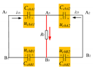
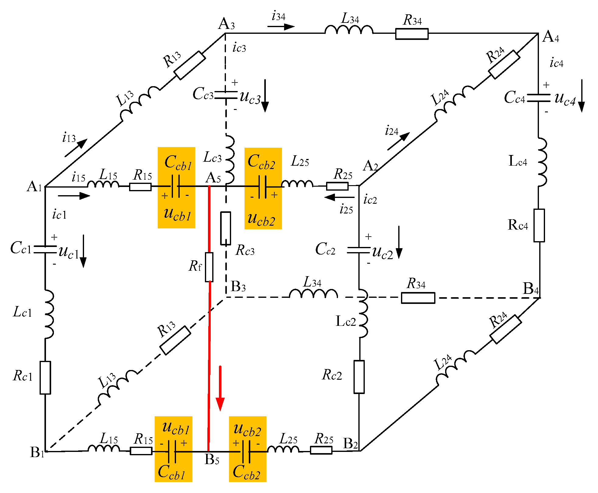
4.2. The Capacitor Equivalent State of CB1 and CB2 (Step:2C)

Since the CB1 and CB2 responds to the breaking command at the same time, in theory, the CB1 and CB2 at both ends of the fault point transfer to the submodule capacitor branch of the transfer branch at the same time. The CB1 and CB2 are equivalent to capacitors connected in series to the line, and the system equivalent circuit is shown in Figure 7. The final state in the state of 2O is the initial state of the system at this time. Similarly, according to KVL and KCL, the differential equations of the system in this state are obtained:
{ u c 1 2 u c b 1 = R c 1 i c 1 L c 1 d i c 1 d t + 2 R 15 i 15 + 2 L 15 d i 15 d t + ( i 15 + i 25 ) R f u c 2 2 u c b 2 = R c 2 i c 2 L c 2 d i c 2 d t + 2 R 25 i 25 + 2 L 25 d i 25 d t + ( i 15 + i 25 ) R f u c 1 u c 3 = R c 1 i c 1 L c 1 d i c 1 d t + 2 R 13 i 13 + 2 L 13 d i 13 d t + i c 3 R c 3 + L c 3 d i c 3 d t u c 3 u c 4 = R c 3 i c 3 L c 3 d i c 3 d t + 2 R 34 i 34 + 2 L 34 d i 34 d t + i c 4 R c 4 + L c 4 d i c 4 d t u c 2 u c 4 = R c 2 i c 2 L c 2 d i c 2 d t + 2 R 24 i 24 + 2 L 24 d i 24 d t + i c 4 R c 4 + L c 4 d i c 4 d t
{ A 0 · u 0 = R 0 · i 0 + L 0 · i 0 · u 0 · = C · A T · i 0
where:
i 0 = [ i 15 i 25 i 13 i 34 i 24 ] T u 0 = [ u c 1 2 u c b 1     2 u c b 2       u c 2 u c 3 u c 4 ] T i c 0 = [ i c 1 i c b 1 i c b 2 i c 2 i c 3 i c 4 ] T C = d i a g [ 1 C c 1 2 C c b 1     2 C c b 2     1 C c 2 1 C c 3 1 C c 4 ]
Since the fault point is close to the MMC1 converter (A1B1) and the fault current rise rate is high, the CB1 current is transferred to the energy absorption branch first, while CB2 still maintains the submodule capacitor branch.

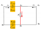
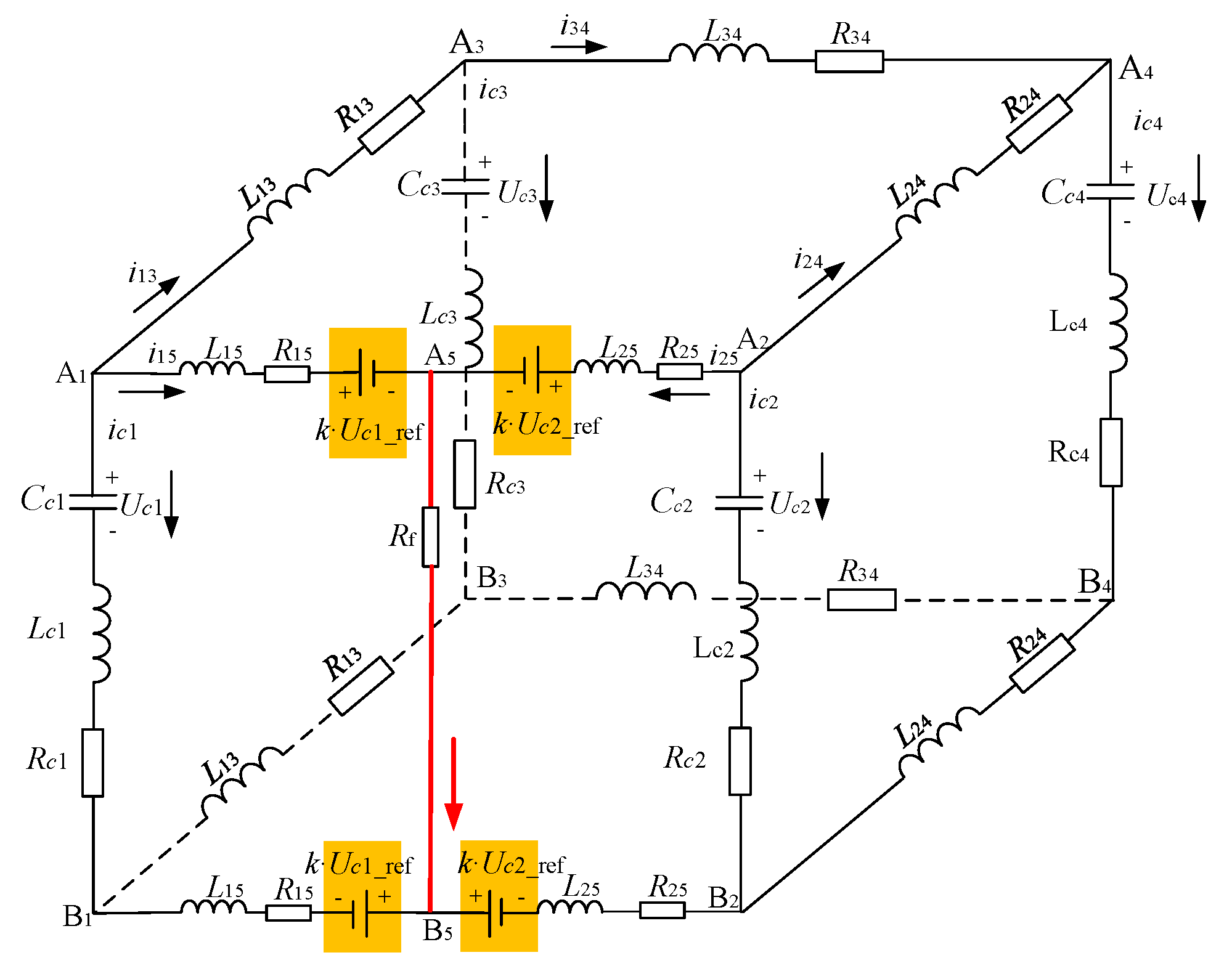
4.3. The DC Source Equivalent State of CB1 and the Capacitor Equivalent State of CB2 (Step:1S1C)

Equivalent circuit of the system in which the CB1 present DC source state and CB2 present capacitor state are shown in Figure 8, where k·Uc1_ref represents the clamping voltage of MOV. According to KVL and KCL, the differential equations of the system in this state are also obtained:
{ u c 1 = R c 1 i c 1 L c 1 d i c 1 d t + 2 R 15 i 15 + 2 L 15 d i 15 d t + ( i 15 + i 25 ) R f + 2 k u c 1 _ r e f u c 2 2 u c b 2 = R c 2 i c 2 L c 2 d i c 2 d t + 2 R 25 i 25 + 2 L 25 d i 25 d t + ( i 15 + i 25 ) R f u c 1 u c 3 = R c 1 i c 1 L c 1 d i c 1 d t + 2 R 13 i 13 + 2 L 13 d i 13 d t + i c 3 R c 3 + L c 3 d i c 3 d t u c 3 u c 4 = R c 3 i c 3 L c 3 d i c 3 d t + 2 R 34 i 34 + 2 L 34 d i 34 d t + i c 4 R c 4 + L c 4 d i c 4 d t u c 2 u c 4 = R c 2 i c 2 L c 2 d i c 2 d t + 2 R 24 i 24 + 2 L 24 d i 24 d t + i c 4 R c 4 + L c 4 d i c 4 d t
{ A 0 · u 0 = R 0 · i 0 + L 0 · i 0 · + B 0 · u r e f u 0 · = C · A T · i 0
where:
i 0 = [ i 15 i 25 i 13 i 34 i 24 ] T u 0 = [ u c 1 2 u c b 2       u c 2 u c 3 u c 4 ] T u r e f = [ 2 k u c 1 _ r e f 0 0 0 0 ] T i c 0 = [ i c 1 i c b 2 i c 2 i c 3 i c 4 ] T C = d i a g [ 1 C c 1 2 C c b 2       1 C c 2 1 C c 3 1 C c 4 ]

4.4. The DC Source Equivalent State of CB1 and CB2 (Step:2S)

When CB2 current is transferred to the energy absorption branch, CB1 and CB2 are equivalent to DC source at the same time, as shown in Figure 9. At this time, the system differential equation is as shown in Equations (17) and (18):
{ u c 1 = R c 1 i c 1 L c 1 d i c 1 d t + 2 R 15 i 15 + 2 L 15 d i 15 d t + ( i 15 + i 25 ) R f + 2 k u c 1 _ r e f u c 2 = R c 2 i c 2 L c 2 d i c 2 d t + 2 R 25 i 25 + 2 L 25 d i 25 d t + ( i 15 + i 25 ) R f + 2 k u c 2 _ r e f u c 1 u c 3 = R c 1 i c 1 L c 1 d i c 1 d t + 2 R 13 i 13 + 2 L 13 d i 13 d t + i c 3 R c 3 + L c 3 d i c 3 d t u c 3 u c 4 = R c 3 i c 3 L c 3 d i c 3 d t + 2 R 34 i 34 + 2 L 34 d i 34 d t + i c 4 R c 4 + L c 4 d i c 4 d t u c 2 u c 4 = R c 2 i c 2 L c 2 d i c 2 d t + 2 R 24 i 24 + 2 L 24 d i 24 d t + i c 4 R c 4 + L c 4 d i c 4 d t
{ A 0 · u 0 = R 0 · i 0 + L 0 · i 0 · + u r e f u 0 · = C · A T · i 0
where:
i 0 = [ i 15 i 25 i 13 i 34 i 24 ] T u 0 = [ u c 1 u c 2 u c 3 u c 4 ] T u r e f = [ 2 k u c 1 _ r e f 2 k u c 2 _ r e f 0 0 ] T i c 0 = [ i c 1 i c 2 i c 3 i c 4 ] T C = d i a g [ 1 C c 1 1 C c 2 1 C c 3 1 C c 4 ]

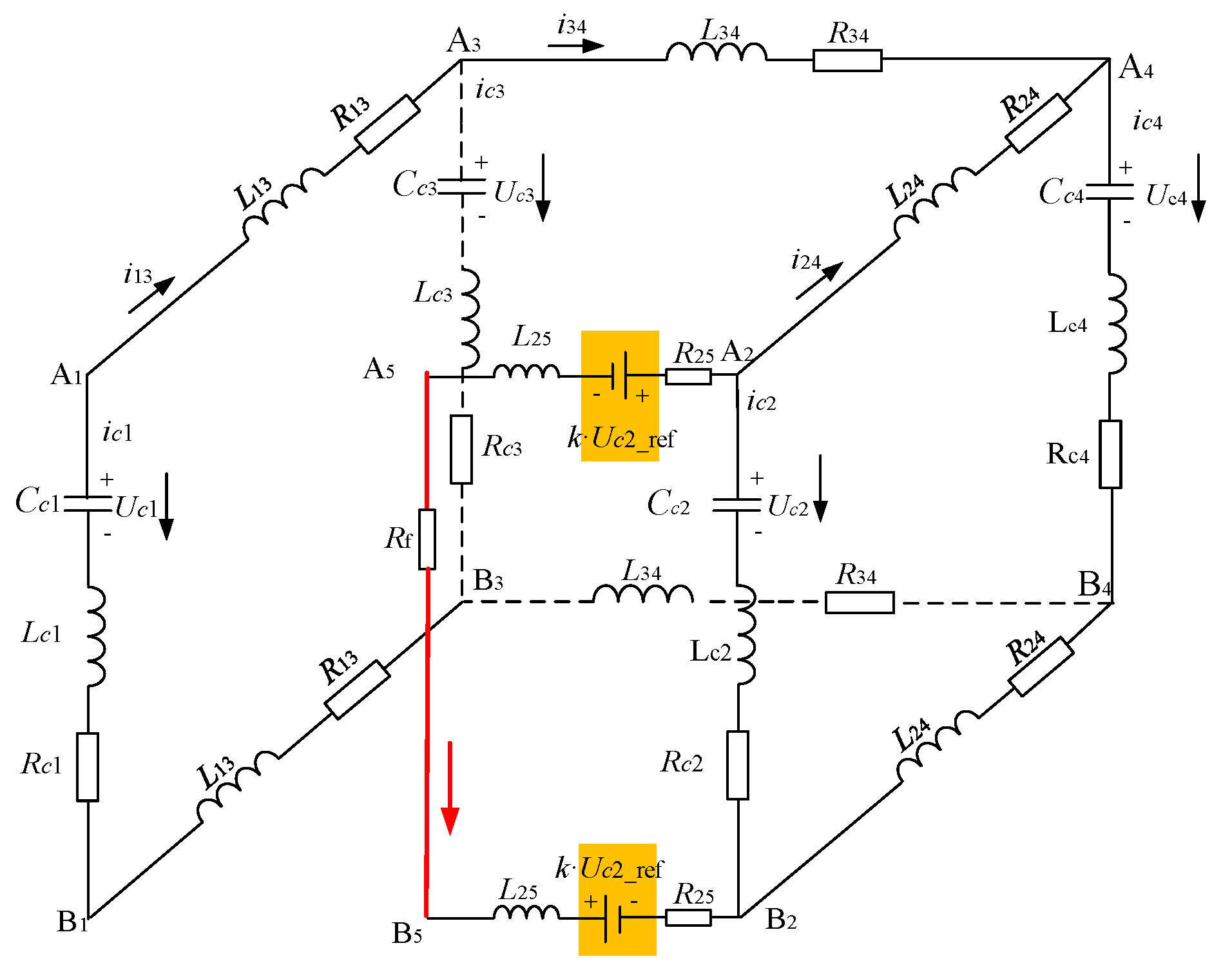
4.5. The Breaking Equivalent State of CB1 and the DC Source Equivalent State of CB2 (Step:1B1S)

When the CB1 current drops to zero, the fault is completely broken. At this time, the CB2 current is still in the energy absorption branch, as shown in Figure 10. At this time, the system differential equation is as follows:
{ u c 2 = R c 2 i c 2 L c 2 d i c 2 d t + 2 R 25 i 25 + 2 L 25 d i 25 d t + ( i 15 + i 25 ) R f + 2 k u c 2 _ r e f u c 1 u c 3 = R c 1 i c 1 L c 1 d i c 1 d t + 2 R 13 i 13 + 2 L 13 d i 13 d t + i c 3 R c 3 + L c 3 d i c 3 d t u c 3 u c 4 = R c 3 i c 3 L c 3 d i c 3 d t + 2 R 34 i 34 + 2 L 34 d i 34 d t + i c 4 R c 4 + L c 4 d i c 4 d t u c 2 u c 4 = R c 2 i c 2 L c 2 d i c 2 d t + 2 R 24 i 24 + 2 L 24 d i 24 d t + i c 4 R c 4 + L c 4 d i c 4 d t
{ A 0 · u 0 = R 0 · i 0 + L 0 · i 0 · + B 0 · u r e f u 0 · = C · A T · i 0
where:
i 0 = [ i 25 i 13 i 34 i 24 ] T u 0 = [ u c 1 u c 2 u c 3 u c 4 ] T u r e f = [ 0 2 k u c 2 _ r e f 0 0 ] T i c 0 = [ i c 1 i c 2 i c 3 i c 4 ] T C = d i a g [ 1 C c 1 1 C c 2 1 C c 3 1 C c 4 ]

4.6. Energy Absorption Power

The energy absorption power calculates is an important part of short circuit calculation. This part will take the DCCB at the MMC1 terminal as an example to calculate the energy absorption of the MOV.
During the energy absorption procedure, the energy absorbed by the MOV is mainly from two aspects: the energy storage of the fault line equivalent inductor and the energy injected by the MMC converter [31]. When the fault loop resistance is ignored (only the metallic short circuit fault is considered), the expression of Ear is as follows:
E a r r A 1 = E a r r B 1 = 1 2 I p e a k 2 L 15 + 0 t n o n i 15 u c 1
Here, Ipeak is the peak value of current flowing through DCCB and Tm is the energy absorption time of MOV. The first item on the right side of Equation (23) is the energy injected by the DC power supply in the fault circuit. The second item on the right side of Equation (23) is the energy storage in the DC line of the fault circuit. During the energy absorption procedure, the voltage at both ends of the MOV is approximately the constant clamping voltage (the protection level of the MOV), which is k times of Uc1_ref. As a result, the fault current reducing rate is:
i 15 · = ( k 1 ) U c 1 _ r e f L 15
During energy absorption, the i15 can be expressed as:
i 15 = ( k 1 ) U c 1 _ r e f L 15 t + I p e a k
Let i15 in Equation (25) be equal to zero, the time when the fault current drops to zero is obtained as:
t n o n = L 15 I p e a k ( k 1 ) U c 1 _ r e f
By substituting Equation (23) into (25), we can get the Emov expression of the energy absorption of the surge arrester as:
E m o v = k L 15 I p e a k 2 2 ( k 1 )

5. Simulation Results

5.1. Basic Parameters of the Simulation System

Matlab/Simulink was used to build a four-terminal pole-to-pole MMC system simulation model with DCCB. The simulation model adopted a four-terminal ring topology structure, with two rectifier stations and two inverter stations. The DC side is a pole-to-pole structure, as shown in Figure 4a, and the main parameters are shown in Table 2. In the simulation system, the main circuit parameters of the four-terminal converter station were the same, and each DC line was equipped with a DCCB at both ends. The DCCB adopted the topological structure shown in Figure 1, and the MMC module adopted the topological structure shown in Figure 3.
The line length and equivalent RL parameters between each converter station are shown in Table 3:
In this model, MMC1 and MMC2 were rectifier stations and MMC3 and MMC4 were inverter stations. Among them, MMC1 station was the main station, which adopted the constant DC voltage control mode to maintain the DC transmission system voltage at 500 kV; the MMC2, MMC3, and MMC4 stations adopted the constant active power control; the four converter stations and their rated capacity are shown in Table 4.

5.2. Short Circuit Calculation Verification

Since the fault current rise rate is the highest and the peak current is the largest when the near end pole-to-pole short-circuit fault occurs [18,19,20], therefore, the system parameter configuration should be designed according to this extreme fault conditions. In this paper, the pole-to-pole short circuit fault condition was used for short circuit calculation and verification.
Combining with the third section of this paper, the calculation process of the four-terminal ring network equivalent circuit with DCCB could complete the analytical solution under the fault. In the calculation process of the analytical solution, the end state of the previous stage of the system model is the initial state of the next stage. The analytical solution of the current and voltage can be obtained by substituting the parameter matrix of each stage into the differential equation of the corresponding equivalent circuit. Table 5 shows the voltage and current value of the system under the rated operation state, that is, the initial value of the voltage and current in Equation (5) before the fault.
The time from the DC protection system detecting the fault to the circuit breaker receiving the fault command was set as 1 ms, so the current and voltage values of each converter station after the fault occurring 1 ms could be obtained as the initial values of the state of 2C by differential Equation (12). The clamping voltage of the MOV and the value of submodule capacitor will directly affect the breaking fault current time and the maximum short-circuit current. At present, the breaking time of hybrid high-voltage DCCB is generally less than 3 ms [18], and the maximum short-circuit current that the circuit breaker can be set as 15 kA according to the rated current [19]. Through the above constraints, the transfer branch submodule capacitor of the circuit breaker is set as 50 uF, and the clamping voltage of the MOV is 800 kV. Since the fault point is set at the near port position of MMC1, L15 and R15 are zero, and R25 and L25 are all line impedance.
Figure 11 is the waveform of the system simulation model after the fault. At 3 s, line A1A2 and B1B2 occurred at the fault, and i15 and i25 rose rapidly. When the capacitor voltage of the submodule was greater than the line voltage, the fault current began to decline. Since the fault point was located near the MMC1, i15 began to decline first. When the capacitor voltage of the submodule exceeded the clamping voltage of the MOV, the MOV started to absorb energy, and the fault current gradually dropped to 0 A. When i15 and i25 were zero, the circuit breaker realized the complete isolation of the fault, and the four-terminal ring network system could still work continuously to maintain the new power transmission state.
According to the initial conditions in Table 5 and the system fault differential equation in Section 3, the analytical solution curve of i15 and i25 under fault was obtained and compared with the simulation curve in Figure 11, as shown in Figure 12. i15calc and i25calc were the calculation results, and i15sim and i25sim were the simulation results. It can be seen that the analytical solution of calculation results was basically consistent with the simulation results before the fault current began to decline. There was a certain difference between the calculation results of the current drop process and the simulation results, because the MOV in the simulation was a nonlinear model, and the calculation process was simplified to the DC voltage source model. The difference of the MOV equivalence did not affect the blocking time and the maximum value of the fault current, and did not affect the subsequent breaker parameter configuration and the selection of system protection setting value.

5.3. Parameter Configuration of DCCB

5.3.1. Submodule Capacitor Configuration

Figure 13 shows the calculation results of the fault current when the pole-to-pole fault occurred at the outlet of the DCCB near MMC1 under the clamping voltage of MOV Vmov = 600 kV and different values of the submodule capacitors of the transfer branch. The fault occurred at t = 0 s. It can be seen from Figure 13 that the smaller the capacitor value of the submodule, the smaller the peak short-circuit current and the shorter the breaking time under the other parameters remaining unchanged. However, too small a capacitor will bring about inconsistent voltage withstanding of switching devices. Theoretically, the capacitor value is zero, which is equivalent to the direct series connection of the switch device of the transfer branch. The larger the capacitor value is, the better the consistency of the voltage withstand of the switch device is. Therefore, when selecting the capacitor value, the capacitor value can be reduced as much as possible under the voltage withstanding the condition of the switching device.

5.3.2. Clamping Voltage Configuration of MOV

Figure 14 shows the calculation results of the fault current when pole-to-pole fault occurs at the outlet of the DCCB near MMC1 under the condition of transfer branch capacitor Ccb = 20 uF and different clamping voltage of MOV Vmov. It can be seen from Figure 14 that under the condition that other parameters remaining unchanged, the clamping voltage of the MOV did not affect the rise time of the fault current (that is the fault current breaking time), but affected the time for the fault current to drop to zero. The larger the clamping voltage of the MOV is, the shorter the time for the current to drop to zero, the less energy the MOV needs to absorb, and the less the reclosing time of the breaker. However, too large of a clamping voltage of the MOV leads to the high voltage withstanding by the submodule capacitor, the switching devices of the submodule also need to withstand high voltage. Therefore, considering the above two factors, the clamping voltage of the MOV was selected.

5.3.3. The Influence of Fault Location at Different Distances

In order to analyze the influence of fault location at different distances, the simulation of a different fault location is shown in Figure 15.
The fault location of Figure 15a is the middle of the line A1B1, and Figure 15b is the farthest distance from MMC1. Figure 11 has shown the fault point close to the A1B1. Three fault types are called respectively near the fault, middle fault, and far fault. Three fault simulations can be plotted together in the same diagram, as shown in Figure 16. The equivalent circuit of the near fault has gone through five stages: 2O-2C-1S1C-2S-1B1S. Since the current direction of the normal condition of line A1B1 is from A1 to B1, no matter the middle fault or the far fault, the equivalent circuit still goes through these five stages: 2O-2C-1S1C-2S-1B1S. The different influence of fault type is the peak fault current and the fault blocking time. For the i15, the near fault is the highest peak fault current, because the line impendence is the minimum from the MMC1 to fault point. Meanwhile the i15 of near fault firstly begins to decrease. On the contrary, the peak value of i25 of the near fault is the minimum because the impendence is the maximum from the MMC2 to the fault point. Since the near fault is the most serious fault for i15, the CB1 parameter design should consider this fault condition. In the same way, the CB2 parameter design should consider the far fault condition and the current direction is from B1 to A1.

5.3.4. Analysis of the Circuit Breaker Parameter Configuration

The main two factors that limit the selection of circuit breaker parameters include the breaking time of the circuit breaker and the maximum current that the line is allowed to flow under fault. It was set that the fault current started to decrease in 4 ms after the fault occurred (1 ms communication delay + 3 ms breaker action time). According to the above short circuit calculation method and system parameters, the maximum current Ipk under the line fault with a different submodule capacitor value and MOV clamping voltage is made, as shown in Figure 17. If 15 kA is taken as the value of the maximum current under line fault, the contour line of the 15 kA vertical coordinate is drawn in Figure 17, and the capacitor value below the red line and the clamping voltage of the MOV were both optional areas. This method could solve the parameter range of DCCB under different requirements, and provide solutions for the parameter design of the circuit breaker and system protection scheme design.

6. Application and Achievement

The aforementioned MMC four-terminal ring DC transmission system contains four MMC converters. In the other DC transmission system, this short-circuit fault current calculation method is still adaptive. In some application scenes, there are constant power loads. If the DC voltage is constant, the power loads is equivalent to the constant current source or resistor. Figure 18 shows the equivalent circuit if one of the four stations is the constant current source.
The short-circuit fault current calculation equations are as follow:
{ u c 1 = R c 1 i c 1 L c 1 d i c 1 d t + 2 R 15 i 15 + 2 L 15 d i 15 d t + ( i 15 + i 25 ) R f R s i R s = 2 R 25 i 25 + 2 L 25 d i 25 d t + ( i 15 + i 25 ) R f u c 1 u c 3 = R c 1 i c 1 L c 1 d i c 1 d t + 2 R 13 i 13 + 2 L 13 d i 13 d t + i c 3 R c 3 + L c 3 d i c 3 d t u c 3 u c 4 = R c 3 i c 3 L c 3 d i c 3 d t + 2 R 34 i 34 + 2 L 34 d i 34 d t + i c 4 R c 4 + L c 4 d i c 4 d t R s i R s u c 4 = 2 R 24 i 24 + 2 L 24 d i 24 d t + i c 4 R c 4 + L c 4 d i c 4 d t
According to KCL, each converter currents are obtained:
{ i c 1 = i 13 i 15 i R s = i 24 i 25 i s i c 3 = i 13 i 34 i c 4 = i 34 + i 24
Combining (28) to (27) yields:
{ u c 1 = R c 1 i 13 + ( R c 1 + 2 R 15 + R f ) i 15 + R f i 25 + L c 1 d i 13 d t + ( L c 1 + 2 L 15 ) d i 15 d t R s i s = R f i 15 + R s i 24 + ( R s + 2 R 25 + R f ) i 25 + 2 L 25 d i 25 d t u c 1 u c 3 = ( R c 1 + 2 R 13 + R c 3 ) i 13 + R c 1 i 15 R c 3 i 34 + ( L c 1 + 2 L 13 + L c 3 ) d i 13 d t                                   + L c 1 d i 15 d t L c 3 d i 34 d t u c 3 u c 4 = R c 3 i 13 + R c 4 i 24 + ( R c 3 + 2 R 34 + R c 4 ) i 34 L c 3 d i 13 d t + L c 4 d i 24 d t                                   + ( L c 3 + 2 L 34 + L c 4 ) d i 34 d t R s i s u c 4 = ( R s + 2 R 24 + R c 4 ) i 24 + R s i 25 + R c 4 i 34 + ( 2 L 24 + L c 4 ) d i 24 d t                                   + L c 4 d i 34 d t
Combining (29) to (30) yields:
i 0 = [ i 15 i 25 i 13 i 34 i 24 ] T u 0 = [ u c 1 R s i s u c 3 u c 4 ] T i c 0 = [ i c 1 i R s i c 3 i c 4 ] T
Therefore, the matrix shown in (30) can be written as:
A 0 · u 0 = R 0 · i 0 + L 0 · i 0 · i c 0 = A 0 T · i 0
where, A0 is the voltage correlation matrix of converter, R0 is the circuit resistance matrix, and L0 is the circuit inductor matrix. The matrix expressions are:
A 0 = [ 1 0 0 1 0 0 0 0 1 0 1 0 0 0 1 1 0 1 0 1 ]
R 0 = [ R c 1 + 2 R 15 + R f R f R c 1 0 0 R f R s + 2 R 25 + R f 0 0 R s R c 1 0 R c 1 + 2 R 13 + R c 3 R c 3 0 0 0 R c 3 R c 3 + 2 R 34 + R c 4 R c 4 0 R s 0 R c 4 R s + 2 R 24 + R c 4 ]
L 0 = [ L c 1 + 2 L 15 0 L c 1 0 0 0 L c 2 + 2 L 25 0 0 0 L c 1 0 L c 1 + 2 L 13 + L c 3 L c 3 0 0 0 L c 3 L c 3 + 2 L 34 + L c 4 L c 4 0 0 0 L c 4 2 L 24 + L c 4 ]
Equations (28)–(35) give the short fault matrix equations of another example. Considering the different transferring process of DCCB as show in Figure 2, the overall short-circuit process could be obtained. That means in a different DC transmission system, especially the MMC DC system, this method still can be extended.
The significance of this paper was offering the short-circuit fault current calculation method considering the DC circuit breaker, and the main achievements were as follows:
  • The commutating process of DC circuit breaker was analyzed, and the equivalent circuit of different transfer branches was obtained.
  • Combining the different transfer branches of DCCB, the short-circuit matrix equations was obtained and analytical values of system current and voltage of the whole DC system were acquired.
  • This method not only could be used in the multi-terminal ring DC system, but the multi-terminal DC system and point-to-point DC system were still applicable. Meanwhile, the DC source could be the MMC converter, DC current source, and power load.
  • The results of the short-circuit fault current calculation could be used to the DC circuit breaker parameters design, MMC converter protection design, and the DC system protection design.

7. Conclusions

In this paper, a method for calculating the fault current of the multi-terminal ring DC grid with a DC circuit breaker was proposed. According to the external characteristics of different branches of the hybrid DC circuit breaker, the equivalent model of each branch was obtained. For the MMC four-terminal ring DC transmission system, the equivalent mathematical model of the system under the fault was given. Combined with the equivalent models of different branches of the DC circuit breaker, the short circuit current calculation of the four-terminal MMC DC system considering the DC circuit breaker was completed.
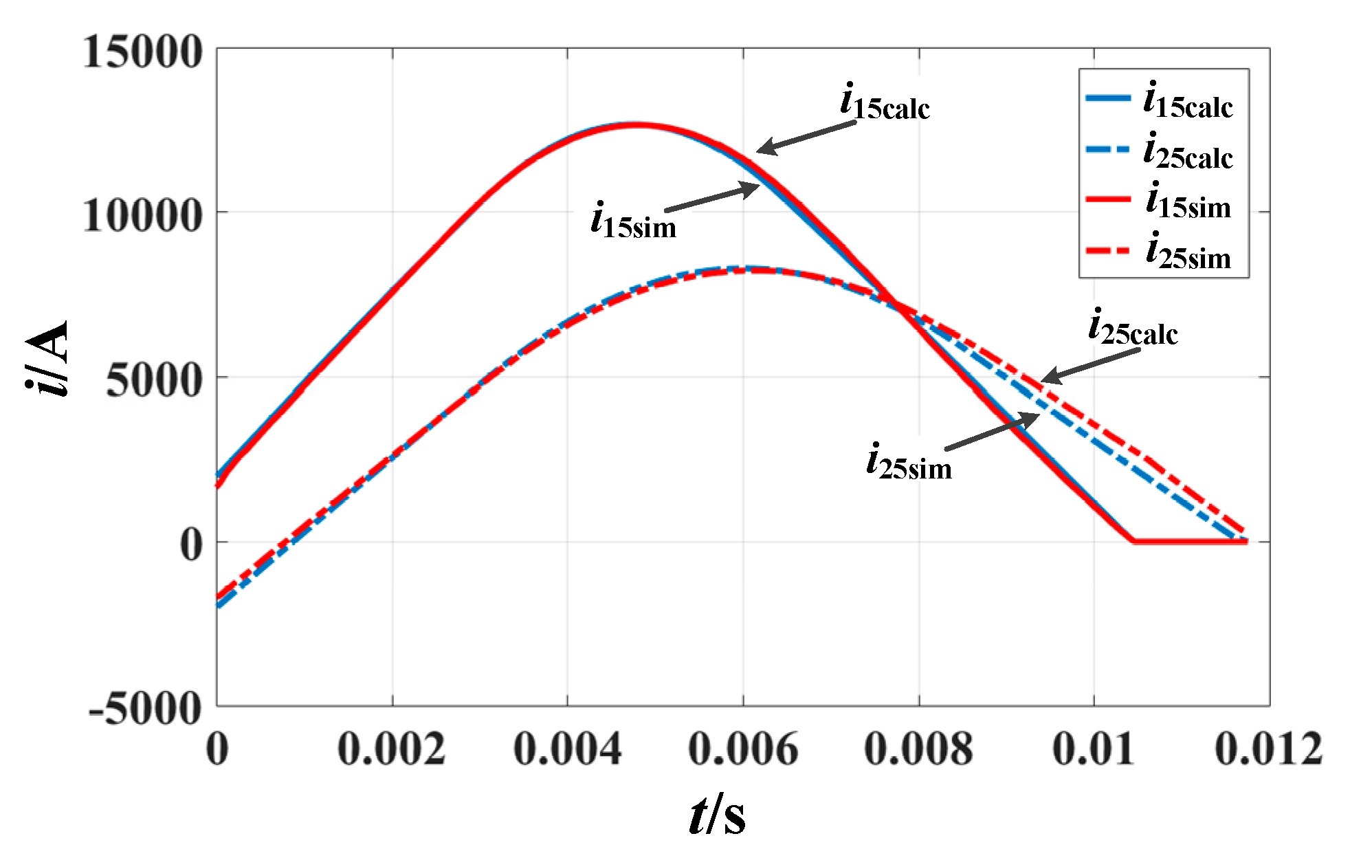
The correctness of the analytical calculation results of the short circuit current considering the DC circuit breaker was verified by system simulation. Combined with specific engineering constraints, the configuration of key parameters of DC circuit breaker was analyzed by using the analytical solution method proposed in this paper. This calculation method could accurately describe the overall trend of fault current, and provided the basis for the selection of DC line protection settings and DC circuit breaker related parameters.

Author Contributions

H.J. conceived and designed the study. J.Y., T.W. and Q.H. given suggestions, J.L. and L.W. revised the manuscript. All authors have read and agreed to the published version of the manuscript.

Funding

This research work was funded by the National Key Research and Development Program of China (2016YFB0900900), Project supported by National Natural Science Foundation of China (51607171), Chinese Academy of Sciences Youth Innovation Association (2017180), Research on the coordinated control technology of PET and FCL in AC/DC system (j2019131), China Postdoctoral Science Foundation (2019M652028).

Conflicts of Interest

The authors declare no conflict of interest.

References

  1. Tang, G.; Luo, X.; Wei, X. Multi-terminal HVDC and DC-grid technology. Proc. CSEE 2013, 33, 8–17. [Google Scholar]
  2. Zongqian, S.; Shenli, J. Research on high voltage direct current circuit breaker: A review. High. Volt. Appar. 2015, 51, 1–9. [Google Scholar]
  3. Wei, X.; Yang, B.; He, Z.; Gao, Y.; Chen, L.; Ke, J. Control strategy and physical dynamic simulation of cascaded full-bridge DC circuit breaker. Autom. Electr. Power Syst. 2016, 40, 129–135. [Google Scholar]
  4. Li, Y.; Shi, X.; Wang, F.; Tolbert, L.M.; Liu, J. DC fault protection of multi-terminal VSC-HVDC system with hybrid DC circuit breaker. In Proceedings of the IEEE Energy Conversion Congress and Exposition, Milwaukee, WI, USA, 18–22 September 2016; IEEE: Cincinnati, OH, USA, 2016; pp. 10–17. [Google Scholar]
  5. Bösche, D.; Wilkening, E.D.; Köpf, H.; Kurrat, M. Hybrid DC circuit breaker feasibility study. IEEE Trans. Compon. Packag. Manuf. Technol. 2017, 7, 354–362. [Google Scholar] [CrossRef]
  6. Xu, Y.; Tan, Z.; Xie, B.; Huang, H.; Lv, Q.; Ban, G.; Yuan, X. Research on Intelligent Protection Configuration Based on DC Breakers for Multi-terminal Flexible DC Distribution Network. Electr. Power Constr. 2018, 39, 69–77. [Google Scholar]
  7. Elserougi, A.A.; Abdel-Khalik, A.S.; Massoud, A.M.; Ahmed, S. A nine-arm modular multilevel converter (9A-MMC) for six-phase medium voltage motor drives. In Proceedings of the Conference of the IEEE Industrial Electronics Society, Yokohama, Japan, 9–12 November 2015; IEEE: New York, NY, USA, 2016. [Google Scholar]
  8. Fu, J.; Zhang, B.; Qiu, D. A novel nine-arm modular multilevel converter. In Proceedings of the Conference of the IEEE Industrial Electronics Society, Dallas, TX, USA, 29 October–1 November 2014; IEEE: New York, NY, USA, 2015. [Google Scholar]
  9. Elserougi, A.A.; Abdel-Khalik, A.S.; Massoud, A.M.; Ahmed, S. An asymmetrical six-phase induction motor drive based on nine-arm Modular Multilevel Converter (9AMMC) with circulating current suppression. In Proceedings of the International Conference on Electric Power & Energy Conversion Systems, Sharjah, UAE, 24–26 November 2015; IEEE: New York, NY, USA, 2015. [Google Scholar]
  10. Cai, X.; Song, G.; Gao, S.; Suonan, J.; Li, G. A novel fault-location method for VSC-HVDC transmission lines based on natural frequency of current. Proc. CSEE 2011, 31, 112–119. (In Chinese) [Google Scholar]
  11. Teng, S.; Song, X.; Li, G.K.; Ye, X.H.; Liu, T.; Zhong, W.Z. A survey on HVDC transmission with modular multilevel converters. Power Syst. Clean Energy 2012, 28, 43–50. (In Chinese) [Google Scholar]
  12. Wei, X.; Gao, C.; Luo, X.; Zhou, W.; Wu, Y. A novel design of high-voltage DC circuit breaker in HVDC flexible transmission grid. Autom. Electr. Power Syst. 2013, 37, 17. [Google Scholar]
  13. Tao, Y.; Jialiang, W.; Jinyuan, L.; Zhongyuan, C. A hybrid high voltage DC circuit breaker design plan with series-connected IGBTs. Power Syst. Technol. 2015, 39, 2484–2489. [Google Scholar]
  14. Davidson, C.C.; Whitehouse, R.S.; Barker, C.D.; Dupraz, J.P.; Grieshaber, W. A new ultra-fast HVDC Circuit breaker for meshed DC networks. In Proceedings of the IET International Conference on AC and DC Power Transmission, Birmingham, UK, 10–12 February 2015; IET: Birmingham, UK, 2015; pp. 1–7. [Google Scholar]
  15. Liu, G.; Xu, F.; Xu, Z.; Zhang, Z.; Tang, G. Assembly HVDC breaker for HVDC grids with modular multilevel converters. IEEE Trans. Power Electron. 2017, 32, 931–941. [Google Scholar] [CrossRef]
  16. Zhang, J.; Xiang, W.; Rao, H.; Wen, J. Research on DC Fault Protection Scheme of Overhead MMC Based DC Grid with DC Circuit Breaker. Proc. CSEE 2018, 38, 4631–4645. [Google Scholar]
  17. Zhang, G.; Qi, X.; Chen, Y.; Qi, L.; Yue, C. Characteristic analysis of modular multilevel converter under DC pole-to-pole short-circuit fault. Autom. Electr. Power Syst. 2016, 40, 151–157. [Google Scholar]
  18. Xu, Z.; Liu, G.; Zhang, Z. Research on fault protection principle of DC grids. High. Volt. Eng. 2017, 43, 1–8. [Google Scholar]
  19. Dong, X.; Tang, L.; Shi, S.; Qiu, Y.; Kong, M.; Pang, H. Configuration scheme of transmission line protection for flexible HVDC grid. Power Syst. Technol. 2018, 42, 1752–1759. (In Chinese) [Google Scholar]
  20. Wei, X.; Gao, C.; Luo, X. Study on a novel HVDC circuit breaker in flexible dc grid. Autom. Electr. Power Syst. 2013, 37, 95–102. [Google Scholar]
  21. Xu, J.; Ding, H.; Fan, S.; Gole, A.M.; Zhao, C. Enhanced high-speed electromagnetic transient simulation of MMC-MTdc grid. Int. J. Electr. Power Energy Syst. 2016, 83, 7–14. [Google Scholar] [CrossRef]
  22. Zhang, Z.; Xu, Z. Short-circuit current calculation and performance requirement of HVDC breakers for MMC-MTDC systems. IEEJ Trans. Electr. Electron. Eng. 2016, 11, 168–177. [Google Scholar] [CrossRef]
  23. Wang, W.; Barnes, M.; Marjanovic, O.; Cwikowski, O. Impact of DC breaker systems on multiterminal VSC-HVDC stability. IEEE Trans. Power Deliv. 2016, 31, 769–779. [Google Scholar] [CrossRef]
  24. Han, P.; Wang, S. Parameter coordination of modular multilevel converter for robust design during dc pole to pole fault. In Proceedings of the China International Conference on Electricity Distribution, Shanghai, China, 10–14 September 2012; pp. 1–5. [Google Scholar]
  25. Zhang, G.; Chen, Y.; Yue, C.; Qi, L.; Pan, J. DC pole-to-pole shortcircuit behavior analysis of modular multilevel converter. In Proceedings of the 2014 IEEE Energy Conversion Congress and Exposition (ECCE), Pittsburgh, PA, USA, 14–18 September 2014; pp. 5698–5702. [Google Scholar]
  26. Rafferty, J.; Xu, L.; Morrow, D.J. DC fault analysis of VSC based multi-terminal HVDC systems. In Proceedings of the IET International Conference on AC and DC Power Transmission (ACDC 2012), Birmingham, UK, 4–5 December 2012; pp. 1–6. [Google Scholar]
  27. CIGRE B4-52 Working Group. HVDC Grid Feasibility Study; International Council on Large Electric Systems: Melbourne, VIC, Australia, 2011. [Google Scholar]
  28. Zhao, C.; Li, T.; Yu, L. DC pole-to-ground fault characteristic analysis and converter fault recovery strategy of MMC-HVDC. Proc. CSEE 2014, 34, 3518–3526. (In Chinese) [Google Scholar]
  29. Li, C.; Zhao, C.; Xu, J.; Ji, Y.; Zhang, F.; An, T. A Pole-to-Pole Short-Circuit Fault Current Calculation Method for DC Grids. IEEE Trans. Power Syst. 2017, 32, 4943–4953. [Google Scholar] [CrossRef]
  30. Liu, S.; Popov, M. Development of HVDC system-level mechanical circuit breaker model. IEEE Trans. Power Deliv. 2018, 103, 159–167. [Google Scholar] [CrossRef]
  31. Liu, S.; Popov, M.; Mirhosseini, S.S.; Nee, S.; Modeer, T.; Ängquist, L.; Belda, N.A.; Koreman, K.; Van der Meijden, M. Modelling, Experimental Validation and Application of VARC HVDC Circuit Breakers. IEEE Trans. Power Deliv. 2019, 99. [Google Scholar] [CrossRef]
Figure 1. Basic structure of the cascade full bridge direct current circuit breaker (DCCB): (a) DCCB topology and (b) breaking process diagram of DCCB.
Energies 13 01347 g001
Figure 2. Fault current transfer process of cascade hybrid DCCB: (a) line normal conduction state; (b) two down IGBTs of full bridge submodule of transfer branch closed state; (c) transfer branch capacitor connected to main circuit state; and (d) energy absorption circuit connected to main circuit state.
Energies 13 01347 g002
Figure 3. Equivalent discharging model of modular multilevel converter (MMC).
Energies 13 01347 g003
Figure 4. Four-terminal ring network MMC DC system with DCCB: (a) four terminal ring network MMC topology and (b) four terminal MMC equivalent circuit with DCCB.
Energies 13 01347 g004
Figure 5. Process diagram of the breaking fault current and voltage with a near MMC1 fault.
Energies 13 01347 g005
Figure 6. Equivalent circuit of the system pole-to-pole fault.
Energies 13 01347 g006
Figure 7. Equivalent circuit of the system in which the CB1 and CB2 present capacitor state at the same time.
Energies 13 01347 g007
Figure 8. Equivalent circuit of the system in which the CB1 presents DC source state and CB2 presents capacitor state.
Energies 13 01347 g008
Figure 9. Equivalent circuit of the system in which the CB1 and CB2 present the DC source state at the same time.
Energies 13 01347 g009
Figure 10. Equivalent circuit of the system in which the CB1 presents the breaking state and CB2 presents the DC source state.
Energies 13 01347 g010
Figure 11. Simulation waveform of the DC line currents during a pole-to-pole fault.
Energies 13 01347 g011
Figure 12. Comparison between simulation results and calculation results of i15 and i25.
Energies 13 01347 g012
Figure 13. Calculation results of short circuit current under different capacitor values of the transfer branch.
Energies 13 01347 g013
Figure 14. Simulation results of the short circuit current under a different clamping voltage of the metal oxide varistor (MOV).
Energies 13 01347 g014
Figure 15. Simulation results of the different fault location: (a) fault location at the middle of the line A1A2 and B1B2 and (b) fault location at the farthest distance from MMC1.
Energies 13 01347 g015
Figure 16. Comparison of different fault locations.
Energies 13 01347 g016
Figure 17. The maximum current under the line fault with a different submodule capacitor value and MOV clamping voltage.
Energies 13 01347 g017
Figure 18. Equivalent circuit of the constant current source.
Energies 13 01347 g018
Table 1. Calculation model of a short circuit under different working conditions of DC circuit breakers at both ends of the fault point.
Serial NumberFault TimeFor ShortSimplified Equivalent Circuit Diagram of Circuit BreakerSerial NumberFault TimeFor ShortSimplified Equivalent Circuit Diagram of Circuit Breaker
1CB1:t0t1
CB2:t0t1
2O Energies 13 01347 i0012CB1:t1t2
CB2:t0t1
1C1O Energies 13 01347 i002
3CB1:t1t2
CB2:t1t2
2C Energies 13 01347 i0034CB1:t2t3
CB2:t1t2
1S1C Energies 13 01347 i004
5CB1:t2t3
CB2:t2t3
2S Energies 13 01347 i0056CB1:t2t3
CB2:t0t1
1S1O Energies 13 01347 i006
7CB1:t3
CB2:t1t2
1B1C Energies 13 01347 i0078CB1:t3
CB2:t2t3
1B1S Energies 13 01347 i008
Table 2. The parameters of the simulation model system.
ParameterValue
AC voltage Uac525 kV
Fundamental frequency f50 Hz
DC voltage Udc±500 kV
Three winding transformer and wiring mode525/66/250; YY
The capacitor of submodular C8000 μF
Arm inductor Lx75 mH
Arm resistance Rx0.147 Ω
Limiting current inductor Lm300 mH
Number of submodular N220
Table 3. The line length and equivalent impedance between converter stations.
Line ParameterResistance Per Unit Length (Ω/km)0.014
Inductor Per Unit Length (mH/km)0.22
Converter StationLength/kmResistance/ΩInductor/mH
MMC1-MMC2205.902.8845.30
MMC1-MMC349.600.7010.91
MMC2-MMC4188.102.6341.38
MMC3-MMC4208.402.9145.85
Table 4. The capacity of the converter station.
ConverterControl ModeRated Capacity
MMC1The constant DC voltage control mode1500 MVA
MMC2The constant active power control (outputting power)−1500 MVA
MMC3The constant active power control (inputting power)3000 MVA
MMC4The constant active power control (outputting power)−3000 MVA
Table 5. Initial values of branch currents and voltages.
Initial currents (kA)i15i25i13i34i24
1.98−1.98−0.4852.52−0.485
Initial voltages (kV)uc1uc2uc3uc4
1000100010001000

