Abstract
In this paper, a model predictive control (MPC) scheme with an enhanced active voltage vector region (AV2R) was developed and implemented to achieve better steady-state performance and lower total harmonic distortion (THD) of the output current for a vehicle-to-grid (V2G) inverter. Firstly, the existing MPC methods conducted with single vector and two vectors during one sampling period were analyzed and the corresponding AV2Rs were elaborated. Secondly, the proposed strategy was investigated, aiming at expanding the AV2R and improving the steady-state performance accordingly. A formal mathematical methodology was studied in terms of duty ratio calculation. Lastly, the proposed method was carried out through experimentation. For comparison, the experimental results of the three mentioned methods were provided as well, proving the effectiveness of the proposed algorithm.
1. Introduction
For the sake of fast development of electric vehicle (EV), pertinent research and studies, such as on motor drive [1], battery charger [2] and vehicle to grid (V2G), have received ever-increasing concern. In particular, the V2G system is increasingly emphasized due to its distinct advantages in terms of both EVs and the grid. With respect to EVs, the function can be expanded through the V2G system, and hence, the cost-effectiveness is increased [3]. Meanwhile, for the power grid, V2G creates some interesting features, e.g., the active and reactive power adjustment, the load balance and the frequency regulation, as well as the improvement of the efficiency, stability and reliability [4,5,6].
As a mobile energy storage unit, the capacity of a single EV is inevitably limited, such as the 4 kWh of the Toyota Prius plug-in hybrid EV and the 85 kWh of the Tesla Model S [3]. Therefore, with respect to the power grid, an individual V2G operation is insufficient and insufficient. However, research on V2G operation for the single EV is still meaningful to alleviate the undesired influence on the grid, especially the current harmonics. This paper concerns the V2G operation of single EV, as shown in Figure 1a. In essence, a V2G structure of the single EV is an inverter connected with the grid and powered by the EV battery. Generally, the mainstream control strategies of the inverter consist of hysteresis current control (HCC) method and proportional-integral (PI) or proportional resonance (PR) controller based on the pulse width modulation (PWM). Particularly, the classical HCC method introduces non-uniform switching frequency, thereby leading to its limited application [7]. To counter this issue, the hysteresis band was modified to operate a uniform switching frequency, while the updated process will inevitably complicate the calculation [8]. With respect to modulation-based control schemes, PI-PWM schemes are utilized to regulate the output current, voltage or power [9]. To obtain better power factor correction performance under the full range of modulation index, a hybrid modulation scheme was provided in [10], where the conventional space vector PWM (SVPWM) was combined with the virtual-vector-based SVPWM. In addition, it should be noticed that the PR-PWM regulator is an alternative solution in terms of the elimination of the steady-state error [11]. Normally, modulation-based PI or PR control strategies feature a good steady-state performance at expenses of reduced dynamic performance, while the parameters tuning in the PI or PR controller is a time-consuming and complex task as well. Another modulation-related method is the combination of model-based dead-beat and the SVM (DB-SVM) strategy [12]. Unlike PI (or PR)-PWM methods, the reference voltage vector in the DB-SVM scheme is directly determined according to the discretized mathematical model of inverter, leading to a faster dynamic response.
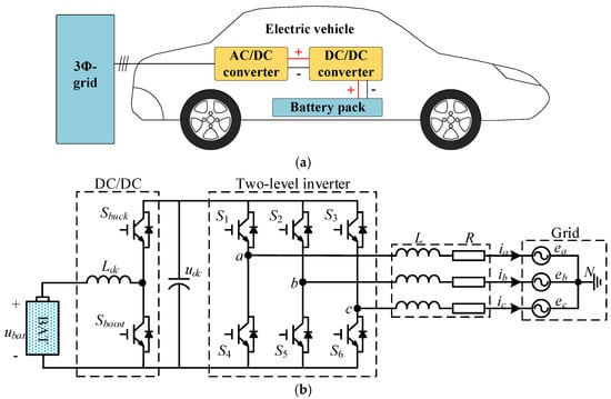
Figure 1.
Vehicle to grid (V2G) system for the single vehicle: (a) Representational figure; (b) The circuit topology.
Recently, the model predictive control (MPC) algorithm has come into the focus of attention since it is characterized by a fast dynamic response, feasible implementation of multi-objective control and strong dynamic decoupling performance [13,14,15,16,17,18,19,20,21]. It has to be mentioned that the MPC method has some drawbacks, including unfixed switching frequency, lower steady-state performance and undesired computation burden [22], and hence, this limits its implementation in industrial application. To perform the constant switching frequency as well as better steady-state performance, numerous improved MPC methods have been presented. In [23], an MPC using discrete space vector modulation (DSVM) is provided while it yields a higher computation burden [24,25], since 12 vectors must be evaluated during one sampling period. Moreover, a novel MPC scheme based on the space vector modulation (SVM) concept is studied and implemented for a three-level inverter in [26], where the optimum voltage vector is generated through nullifying the derivative of the cost function. In addition, an improved MPC with second modification has been successfully developed for a three-level converter in [27], where the duty-ratios of three vectors are reasonably regulated to achieve a better steady-state performance. In particular, when compared with the DB-SVM method, this scheme can readily realize the multi-objective control by the employment of cost function. Unfortunately, the computation burden is ultra high due to the second optimization for mickle combinations of cost function values [28]. On the whole, these improved arts are to extend the active voltage vector region (AV2R), which will be discussed in Section 2.2, while the computation burden is highly increased, thus complicating the optimization process.
To achieve enhanced AV2R and improved steady-state performance, this paper studies an MPC method in conjunction with SVM concept. Meanwhile, the good dynamic performance of traditional MPC is retained and fixed switching frequency can be acquired in a manner two adjacent active vectors and two null vectors are applied during one sampling period. Significantly, a formal mathematical methodology is conducted in terms of duty ratio calculation for null and active vectors. Moreover, an SVM-based PWM generation method is studied, aiming at reducing the on/off losses and unifying the switching frequency.
This paper is organized as follows: in Section 2, the mathematical model of two-stage grid-connected inverter for V2G is given and analyzed, which consists of a three-phase inverter and a DC/DC converter. Meanwhile, three existing MPC methods for inverter are analyzed and then the AV2Rs in these methods are elaborated. The proposed MPC method that comprises the duty-ratio calculation of the null vector and active vectors determination is conducted in Section 3, where the implementation of AV2R in the proposed method is also discussed. In Section 4, experimental results are examined to verify the effectiveness of the proposed method. Finally, conclusions are presented in Section 5.
2. Modeling and Control of Grid-Connected Inverter for V2G
2.1. Modeling of Two-Stage Grid-Connected Inverter
Referring to Figure 1b, a two-stage grid-connected inverter for V2G is studied in this paper. A DC/DC converter is employed to match the battery voltage and the dc-link voltage, while the two-level inverter converts DC power to AC power absorbed by the grid.
In general, the battery voltage of EV is rated from 300 V to 400 V. However, with respect to the grid-connected inverter, the restriction between dc-link voltage and grid-side voltage must be satisfied as:
where udc is the dc-link voltage of the inverter; eline is the line-voltage of the grid rated at 380 V as in China.
Due to the bidirectional circuit in the cascaded structure as shown in Figure 1, two operating modes can be initiated, i.e., charging mode and V2G mode. For charging mode, it has to be noticed that the DC/DC part is operated as a buck converter, while the two-level inverter is carried out as a rectifier. In turn, the system is powered by the battery if V2G mode is initiated. In this case, the DC/DC converter operated as a boost circuit upgrades the battery voltage to fulfill the requirement of udc. Out of the two modes, the V2G operation is targeted for this paper. Concerning the required DC/DC converter, the mathematical model can be derived as:
where Dboost is the duty cycle of Sboost; ubat means the battery voltage.
Next, according to the Kirchhoff voltage law, the mathematical model of the grid-connected inverter can be deduced as:
where L is the output filter inductance; R is the line resistance; ei and ii (i = a, b, c) are the grid voltages and output currents, respectively; uiN is the converter-side voltage, determined by the switching states Si. For the sake of conciseness, Si = 1 means the upper switch of phase i is ON, while Si = 0 means the down switch is ON.
Note that (3) is established at each instant, thus, regulation of the output currents can be realized by varying the states of Si. However, due to the inter-coupling relationship among three phases, the design of the control strategy based on (3) is very demanding. Generally, it is widely acknowledged that the decoupling methods can be implemented at two different coordinate planes, i.e., αβ and dq frames. In this study, a Park’s transformation with invariant amplitude criterion is applied as:
where θ is the angle of the d-axis relative to the a-axis.
Thereafter, the mathematical model of grid-connected inverter in dq frame can be deduced as:
where the subscripts d and q imply the d-q axis components; ω is the angle frequency of grid voltage.
In essence, the MPC method is a discrete solution to optimize the future behavior of the system, which is applicable in the digital controller. Thus, the continuous model shown in (5) should be transformed to the discrete model. For the sake of simplicity, the future behavior of the control variables is deduced by the forward Euler method as:
where the superscript k represents the kth sampling period; Ts is the sampling period.
2.2. Existing MPC Methods and Corresponding AV2Rs
For a two-level inverter, eight feasible voltage vectors (six active and two null voltage vectors) can be obtained according to the switching states, as presented in Figure 2a. In classical MPC method (termed as MPC1), the system can be simultaneously controlled by evaluating a cost function. With respect to the mentioned V2G inverter, the objective is to regulate the output current i = [id, iq]T. Hence, the cost function can be constructed as:
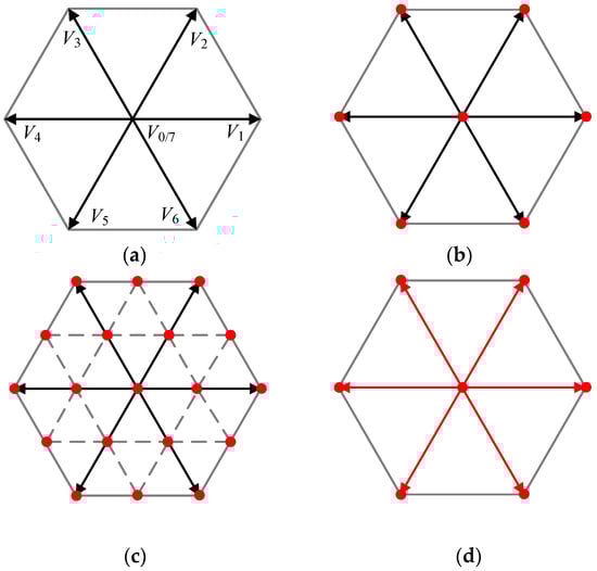
Figure 2.
Feasible voltage vectors and active voltage vector region (AV2R) of existing model predictive control (MPC) methods: (a) Feasible voltage vectors; (b) AV2R of MPC1; (c) AV2R of MPC2; (d) AV2R of MPC3.
Thereafter, eight feasible vectors are utilized to evaluate the cost function and the optimal vector is selected by minimizing the cost function. Nevertheless, since the switching state alternates between 0 and 1, the AV2R (highlighted with red) is insufficient and seven points are merely covered from the graphical subject of view, as observed in Figure 2b. As such, the applied vector is limited to these points. In this manner, the locus of applied vectors is necessarily discontinuous, and therefore, the control effect is also relatively limited.
To this end, an improved strategy using the DSVM method is studied in [23], termed as MPC2. Twelve virtual vectors in conjunction with eight actual vectors are evaluated during each sampling period. Hence, as illustrated in Figure 2c, the AV2R is extended to 19 points from seven points, which results in that the computation burden is increased extremely. Furthermore, a duty-ratio-based MPC is developed for a three-level inverter in [26], termed MPC3. Carrying out this algorithm in the two-level inverter, AV2R of six lines can be covered due to that the null vector is inserted as shown in Figure 2d. However, both of these two arts still suffer from the problem of an inadequate AV2R, and hence, the discontinuous locus of applied vectors.
Comparatively, the art proposed in [27] for a three-level converter is outperforming in terms of the AV2R. When this method is extended to the two-level inverter, the AV2R will reach the whole hexagon region. Nevertheless, all the actual vectors as well as the vector combinations of the six sectors should be assessed in the two-level inverter, which will introduce an exceptionally high computation burden.
3. Proposed MPC Method
From the aforementioned analysis, although MPC2 and MPC3 schemes can provide a better performance, both of them are weak if they stack up against the conventional PI-SVPWM method, which can yield an AV2R of the whole hexagon area. In order to address this issue, a four-vector-based MPC is proposed, in which two adjacent active vectors along with two null vectors are applied during each sampling period. In this way, a modulation-like behavior can be realized, yielding the desired steady-state performance and unifying the switching frequency. Meanwhile, it should be mentioned that the excellent dynamic response inherent to the classical MPC can be retained. The control diagram of the proposed MPC is presented in Figure 3. Each part is elaborated as follows.
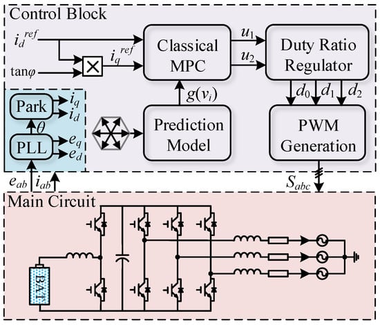
Figure 3.
Control block of the proposed MPC method.
3.1. Determination for Two Active Voltage Vectors
In the classical MPC, an optimal vector can be selected through the evaluation of cost function. Based on this concept, two active vectors are selected with a two-stage cascaded algorithm.
The first stage is to determine the optimal vector using conventional MPC. It is noteworthy that the number of voltage vector candidates is six (V1-V6) instead of eight. For the sake of convenience, the optimal vector is counted as u1. Next, the second stage is to decide the suboptimal vector (termed as u2) from the vectors adjacent to the optimal one. For instance, supposing that the optimal vector is V1, then V2 and V6 are the two adjacent vectors and selected as the candidates associated with the suboptimal vector. Then, if the cost function value generated by V2 is smaller than that generated by V6, V2 will be selected as the suboptimal vector and vice versa. In the same manner, the candidate vectors can be picked out for the other cases (as listed in Table 1), and the suboptimal vector can be determined.

Table 1.
Optimal vector and corresponding candidates associated with the suboptimal vector.
3.2. Duty Ratio Regulator
In fact, according to the traditional PI-SVPWM method, the locus of applied vectors is generally round in shape within the hexagon range illustrated in Figure 2a, where the null vectors are commonly adopted for the better steady-state performance. Therefore, apart from two active vectors determined in Section 3.1, two null vectors V0 and V7 (counted as u0) are inserted during each sampling period as well. This subsection introduces a formal mathematical methodology and targets the calculation of the duration for u0, u1 and u2.
Indeed, the value of cost function (7) expresses the square of current error, termed as ε2. Since the sampling period is extremely short in general, this error could be mentioned as a linear variable relevant to the duration of the corresponding vector [27]. Hence, considering the case where u0, u1 and u2 are applied and their durations are d0, d1 and d2, the value of cost function can be approximated as:
where ε(uk)2 (k=0, 1 or 2) is equal to the corresponding cost function value generated by uk.
Note that d0, d1 and d2 subject to the following constraints:
In this manner, the objective is to determine an optimal set of duty ratios with respect to a given (u0, u1, u2), thereby minimizing (8) accordingly. This optimization along with constraints is usually called as the conditional extremum problem, which could be effectively solved by employing the well-noted Lagrange multipliers method in conjunction with the Hessian matrix. By these means, the optimal set of duty ratios, termed as (d0*, d1*, d2*), can be calculated by the utilization of (10) and the Hessian matrix G is provided in (11). Particularly, G is a positive definite matrix with respect to the calculated (d0*, d1*, d2*); namely, this set of duty ratios corresponds to the minimum point of (8). In fact, this problem can be solved using the convex optimization theory and the same result can be deduced as well.
3.3. PWM Generation
For the power electronics and inverter-based machine drive, the PWM generation strategy is the final step of the digital implementation. Since both the proposed method and SVM strategy apply two adjacent active vectors and two null vectors during each sampling period, their PWM generations are essentially the same, as illustrated in Figure 4. For example, assuming that the two selected active vectors are V1 and V2, the sequence of vector actions is V0-V1-V2-V7-V2-V1-V0, as shown in Figure 4a. This operation provides two interesting features simultaneously. On the one hand, just one-phase switching state alters at any instant and reduces the switching loss to some extent. On the other hand, similar to the conventional PI-SVPWM method, the switching frequency is unified since the switching state changes twice during each sampling period. This feature creates an advantage worth mentioning in terms of filter design.
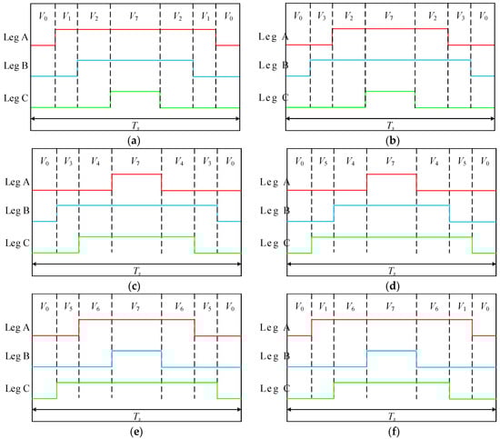
Figure 4.
The sequence of vector actions for different vector combinations: (a) V1 and V2; (b) V2 and V3; (c) V3 and V4; (d) V4 and V5; (e) V5 and V6; (f) V6 and V1.
3.4. AV2R Analysis and Summary of the Proposed MPC
Consequently, the proposed method can enhance the AV2R and improves the steady-state performance consequently. Note that (d0*, d1*, d2*) is calculated by solving the optimization problem with constraints shown in (10), which ensure (d0*, d1*, d2*) is a feasible solution. Hence, the proposed method can expand the AV2R to the region of the whole hexagon theoretically, as presented in Figure 5. Compared to three methods of MPC1-3, since all vectors within the hexagon can be generated, the proposed method yields a sufficient AV2R to create the continuous locus of applied vectors and hence leads to a better steady-state performance.
Figure 5.
AV2R of the proposed MPC method.
To sum up, the implementation of the Lagrange multipliers method to determine the duration of the null vector and two active vectors is the core idea of this paper. The process of the proposed algorithm steps can be listed as follows.
Step 1. Measurement of grid-voltage and output currents. Then, to calculate θ, id, iq, ed and eq using phase-locked-loop (PLL) and Park’s transformation.
Step 2. Determination of two active voltage vectors using MPC1, as discussed in Section 3.1.
Step 3. Duty ratio calculation for null and active vectors, as discussed in Section 3.2.
Step 4. PWM generation based on the SVM concept, as discussed in Section 3.3.
4. Experimental Results
In order to verify the effectiveness of the proposed method, a test prototype of the grid-connected inverter was conducted, as shown in Figure 6. For the AC-side, a 1 kW three-phase transformer was utilized. Both primary and secondary windings of the transformer were Y-connected, while the neutral point was not elicited, and the ratio was 10:1. Meanwhile, three inductors with 5 mH/0.7 Ω were employed as the output filter inductances. For DC-link, an adjustable dc power supply was used to emulate an EV battery and the dc/dc converter was not required consequently. The dc power supply could provide a maximum voltage of 300 V, while the tested voltage was 150 V. Moreover, the three-leg inverter consisted of three FF300R12ME4 (Infineon) modules. Two current sensors WHB25LSP3S1 were utilized to measure the output currents (ib and ic). The grid voltages (eab and ebc) and dc-link voltage were measured using three voltage sensors WHV05AS3S6. Furthermore, a TMS320F28335 digital signal processor was employed to implement the real-time control code, which was developed with C language in Code Composer Studio 6. 0. The sampling frequency was set to 10 kHz. What should be noted is that the grid voltage ea was exported to the oscilloscope through digital to analog (D/A) channel since the neutral point of the used transformer was not elicited. Here, a D/A chip AD5344BRU was utilized to implement the D/A function.
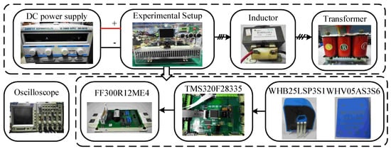
Figure 6.
Experimental setup.
4.1. Steady-State Performance Comparison
At first, the steady-state performance comparison was carried out. The d-axis current reference idref was set to 8 A and the power factor angle φ was set to 0. In this case, the inverter was operated under the unity power factor condition. The total harmonic distortion (THD) analysis was conducted using the fast Fourier transform (FFT) tool of the MATLAB/Simulink powergui block.
The results are presented in Figure 7. It can be observed that the four MPC methods yielded sinusoidal output currents and the peak-value of currents was about 8 A. Meanwhile, the unity power factor operation could be realized. However, MPC1, MPC2 and MPC3 provided THDs of 19.73%, 15.68% and 17.28%, respectively. Comparatively, the THD generated with the proposed MPC was within 10%. This extreme improvement was as expected since the proposed MPC can extend the AV2R to the whole hexagon instead of some points or lines in the existing arts. In other words, the proposed MPC can create a continuous-changed control signal, while the existing methods just created step-changed signals. This comparison proves that the steady-state performance can be greatly enhanced and the tracking accuracy can be realized using the proposed MPC.
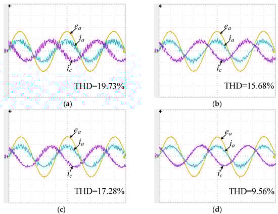
Figure 7.
Steady-state performance of four MPC methods (20 V/div, 10 A/div, 5 ms/div): (a) MPC1; (b) MPC2; (c) MPC3; (d) Proposed MPC.
4.2. Dynamic Performance Comparison
Next, the d-axis current reference step-change test was implemented to investigate the dynamic performance of the proposed MPC method. The d-axis current reference idref was suddenly changed from 8 A to 5 A. Meanwhile, it should be noticed that the power factor angle φ was maintained as 0 to ensure the unity power factor operation.
The experimental waveforms are illustrated in Figure 8. Four MPC methods can provide a fast transient of the current response. Meanwhile, the unity power factor operation can also be realized under the post-step-change condition. The peak-value of phase currents was about 8 A and 5 A in the two cases, respectively. This comparison indicates that the proposed art does not sacrifice the dynamic performance to generate a better steady-state performance. Indeed, MPC methods determined an optimal control signal to regulate the control variable and the proposed method provided a novel implementation of optimization process while it retained the excellent dynamic performance of the classic MPC method.
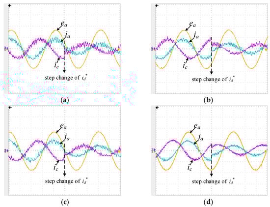
Figure 8.
Dynamic performance of four MPC methods (20 V/div, 10 A/div, 5 ms/div): (a) MPC1; (b) MPC2; (c) MPC3; (d) Proposed MPC.
4.3. Performance under Non-Unity Power Factor Conditions
With respect to the V2G system, the adjustment of active and reactive power was an essential task. To evaluate the gird-connection performance under the non-unity power factor conditions, two cases where the power factor angle φ was suddenly changed from 0 to π/6 and from 0 to –π/6 were implemented, respectively. The results are presented in Figure 9.
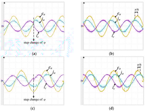
Figure 9.
Performance of non-unity power factor conditions (20 V/div, 10 A/div, 5 ms/div): (a) Dynamic performance under the condition of φ is suddenly changed from 0 to π/6; (b) Steady-state performance under φ is π/6; (c) Dynamic performance under the condition of φ is suddenly changed from 0 to -π/6; (d) Steady-state performance under φ is -π/6.
From Figure 9a,c, it can be found that excellent dynamic response can be achieved when φ had a sudden change. In particular, from Figure 9b, the phase current ia was shifted about π/6 with respect to ea and the peak-value of the phase current had a slight increase, which can be explained by the fact that iqref desires a non-zero value under non-unity power factor condition. A similar result can be seen in Figure 9d, and a shifted angle of –π/6 of phase current can be generated. These results validated that excellent performance under non-unity power factor conditions can be obtained using the proposed MPC.
4.4. Some Discussions
The obtained results verify that the proposed method can provide better steady-state performance and maintain the inherited dynamic capability. Nevertheless, there are several practice-related issues that should be further discussed.
On the one hand, with respect to the equal voltage value, a DC power supply performs the same electrical characteristic as a healthy battery pack installed onboard the EV when the consideration of battery internal resistance variation is ignored, hence, it is quite feasible to conduct the proof-concept prototype with a DC power supply. It should also be noted that this replacement will be ill-suited when the battery pack suffers from internal resistance variation during a long-term deep discharge process. In practice, the higher internal resistance will lead to a relatively lower output voltage, which may yield an unsatisfactory implementation of the V2G system.
On the other hand, when the grid current has a peak value of 8 A, the voltage loss on the filter inductor will be about 18% (with respect to the voltage of the transformer’s secondary side) due to the 0.7 Ω internal resistance of the filter inductor. To compensate for the voltage loss, the dc-link voltage must be increased, which in turn results in a large current ripple as observed in the experimental results. For the alleviation of the problems of the high dc-link voltage accompanied with the large current ripple, the filter inductor with lower internal resistance can be theoretically adopted. Moreover, the utilization of LCL filter can be regarded as an alternative solution because it holds the definite merit of a better performance in terms of the electromagnetic interference suppression.
5. Conclusions
In this paper, an MPC method with an enhanced AV2R was proposed for a two-level grid-connected inverter. First of all, three existing MPC methods and the corresponding AV2Rs were analyzed and discussed. Thereafter, to improve the steady-state performance of the MPC method, a formal mathematical methodology was studied in terms of duty-ratio calculation, in which the well-known Lagrange multipliers method and the Hessian matrix were applied. The AV2R of the proposed MPC method and an SVM-based PWM generation strategy were elaborated as well. Finally, the experimental results of the proposed MPC were presented. Moreover, to prove the effectiveness of the proposed method, three mentioned MPC methods were conducted. The comparative results verified that the proposed MPC method can improve the steady-state performance and retain the excellent dynamic performance of the classic MPC method simultaneously. Furthermore, the grid-connected operation under non-unity power factor conditions can also be realized using the proposed art, ensuring that the V2G system is characterized with excellent performance under different desired power factor.
Author Contributions
Conceptualization, L.X. (Lie Xia), L.X. (Lianghui Xu), F.Y.; Methodology, L.X. (Lie Xia); Software, L.X. (Lie Xia); Validation, L.X. (Lie Xia), L.X. (Lianghui Xu) and Q.Y.; Formal Analysis, L.X. (Lie Xia) and Q.Y.; Investigation, L.X. (Lie Xia); Resources, L.X. (Lianghui Xu) and Q.Y.; Data Curation, L.X. (Lie Xia) and L.X. (Lianghui Xu); Writing-Original Draft Preparation, L.X. (Lie Xia); Writing-Review & Editing, F.Y. and S.Z.; Visualization, L.X. (Lie Xia), L.X. (Lianghui Xu) and Q.Y.; Supervision, S.Z. Project Administration, S.Z.; Funding Acquisition, Q.Y. All authors have read and agreed to the published version of the manuscript.
Funding
This research was funded by the National Key Research and Development Program of China (2018YFB1500705).
Conflicts of Interest
The authors declare no conflict of interest.
References
- Cheng, M.; Yu, F.; Chau, K. Dynamic performance evaluation of a nine-phase flux-switching permanent-magnet motor drive with model predictive control. IEEE Trans. Ind. Electron. 2016, 63, 4539–4549. [Google Scholar] [CrossRef]
- Yu, F.; Zhang, W.; Shen, Y. A nine-phase permanent magnet electric-drive-reconstructed onboard charger for electric vehicle. IEEE Trans. Energy Convers. 2018, 33, 2091–2101. [Google Scholar] [CrossRef]
- Chau, K. Electric Vehicle Machines and Drives: Design, Analysis and Application; Wiley Press: Hoboken, NJ, USA, 2015. [Google Scholar]
- Koyanagi, F.; Uriu, Y. A strategy of load leveling by charging and discharging time control of electric vehicles. IEEE Trans. Power Syst. 1998, 13, 1179–1184. [Google Scholar] [CrossRef]
- Yilmaz, M.; Krein, P.T. Review of the impact of vehicle-to-grid technologies on distribution systems and utility interfaces. IEEE Trans. Power Electron. 2013, 28, 5673–5689. [Google Scholar] [CrossRef]
- Nunna, H.; Battula, S.; Doolla, S. Energy management in smart distribution systems with vehicle-to-grid integrated microgrids. IEEE Trans. Smart Grid 2018, 9, 4004–4016. [Google Scholar] [CrossRef]
- Rahman, K.; Khan, M.; Choudhury, M. Implementation of programmed modulated carrier HCC based on analytical solution for uniform switching of voltage source inverters. IEEE Trans. Power Electron. 2003, 18, 188–197. [Google Scholar] [CrossRef]
- Komurcugil, H.; Bayhan, S.; Abu-Rub, H. Variable- and fixed-switching-frequency-based HCC methods for grid-connected VSI with active damping and zero steady-state error. IEEE Trans. Ind. Electron. 2017, 64, 7009–7018. [Google Scholar] [CrossRef]
- Gonçalves, A.; Aguiar, C.; Bastos, R. Voltage and power control used to stabilise the distributed generation system for stand-alone or grid-connected operation. IET Power Electron. 2016, 9, 491–501. [Google Scholar] [CrossRef]
- Jiang, W.; Du, S.; Chang, L. Hybrid PWM strategy of SVPWM and VSVPWM for NPC three-level voltage-source inverter. IEEE Trans. Power Electron. 2010, 25, 2607–2619. [Google Scholar] [CrossRef]
- Zmood, D.; Holmes, D. Stationary frame current regulation of PWM inverters with zero steady-state error. IEEE Trans. Power Electron. 2003, 18, 814–822. [Google Scholar] [CrossRef]
- Cheng, C.; Nian, H.; Wang, X. Dead-beat predictive direct power control of voltage source inverters with optimised switching patterns. IET Power Electron. 2017, 10, 1438–1451. [Google Scholar] [CrossRef]
- Pedro, G.; Sérgio, C.; André, M. Finite control set model predictive control of six-phase asymmetrical machines—An overview. Energies 2019, 12, 4693. [Google Scholar]
- Wang, W.; Lu, Z.; Hua, W. Simplified model predictive current control of primary permanent-magnet linear motor traction systems for subway applications. Energies 2019, 12, 4144. [Google Scholar] [CrossRef]
- Yu, F.; Liu, X.; Zhang, X. Model predictive virtual-flux control of three-phase Vienna rectifier without voltage sensors. IEEE Access 2019, 7, 169338–169349. [Google Scholar] [CrossRef]
- Formentini, A.; Trentin, A.; Marchesoni, M. Speed finite control set model predictive control of a PMSM fed by matrix converter. IEEE Trans. Ind. Electron. 2015, 62, 6786–6796. [Google Scholar] [CrossRef]
- Siami, M.; Khaburi, D.; Rivera, M. A computationally efficient lookup table based FCS-MPC for PMSM drives fed by matrix converters. IEEE Trans. Ind. Electron. 2017, 64, 7645–7654. [Google Scholar] [CrossRef]
- Daniel, W.; Ryszard, S. Sensorless predictive control of three-phase parallel active filter. In Proceedings of the AFRICON 2007, Windhoek, South Africa, 26–28 September 2007. [Google Scholar]
- Krzysztof, K. Model predictive control of five-level ANPC converter with reduced number of calculations. In Proceedings of the 2019 PRECEDE, Quanzhou, China, 31 May–2 June 2019. [Google Scholar]
- Abousoufiane, B.; Kamel, K.; Aissa, C. Prediction-based deadbeat control for grid-connected inverter with L-filter and LCL-filter. Electr. Power Compon. Syst. 2014, 42, 1266–1277. [Google Scholar]
- Novak, M.; Dragicevic, T. Supervised imitation learning of finite set model predictive control systems for power electronics. IEEE Trans. Ind. Electron. 2020. [Google Scholar] [CrossRef]
- Aguirre, M.; Kouro, S.; Rojas, C. Switching frequency regulation for FCS-MPC based on a period control approach. IEEE Trans. Ind. Electron. 2018, 65, 5764–5773. [Google Scholar] [CrossRef]
- Hassine, I.; Naouar, M.; Mrabet-Bellaaj, N. Model predictive-sliding mode control for three-phase grid-connected converters. IEEE Trans. Ind. Electron. 2017, 64, 1341–1349. [Google Scholar] [CrossRef]
- Vazquez, S.; Leon, J.; Franquelo, L. Model predictive control with constant switching frequency using a discrete space vector modulation with virtual state vectors. In Proceedings of the 2009 IEEE International Conference on Industrial Technology, Gippsland, VIC, Australia, 10–13 February 2009. [Google Scholar]
- Alam, K.; Xiao, D.; Akter, M. Modified model predictive control with extended voltage vectors for grid-connected rectifier. IET Power Electron. 2018, 11, 1926–1936. [Google Scholar] [CrossRef]
- Sebaaly, F.; Vahedi, H.; Kanaan, H. Novel current controller based on MPC with fixed switching frequency operation for a grid-tied inverter. IEEE Trans. Ind. Electron. 2018, 65, 6198–6205. [Google Scholar] [CrossRef]
- Donoso, F.; Mora, A.; Cárdenas, R. Finite-Set model-predictive control strategies for a 3L-NPC inverter operating with fixed switching frequency. IEEE Trans. Ind. Electron. 2018, 65, 3954–3965. [Google Scholar] [CrossRef]
- Xiao, D.; Alam, K.; Norambuena, M. Modified modulated model predictive control strategy for a grid-connected converter. IEEE Trans. Ind. Electron. 2020. [Google Scholar] [CrossRef]


© 2020 by the authors. Licensee MDPI, Basel, Switzerland. This article is an open access article distributed under the terms and conditions of the Creative Commons Attribution (CC BY) license (http://creativecommons.org/licenses/by/4.0/).