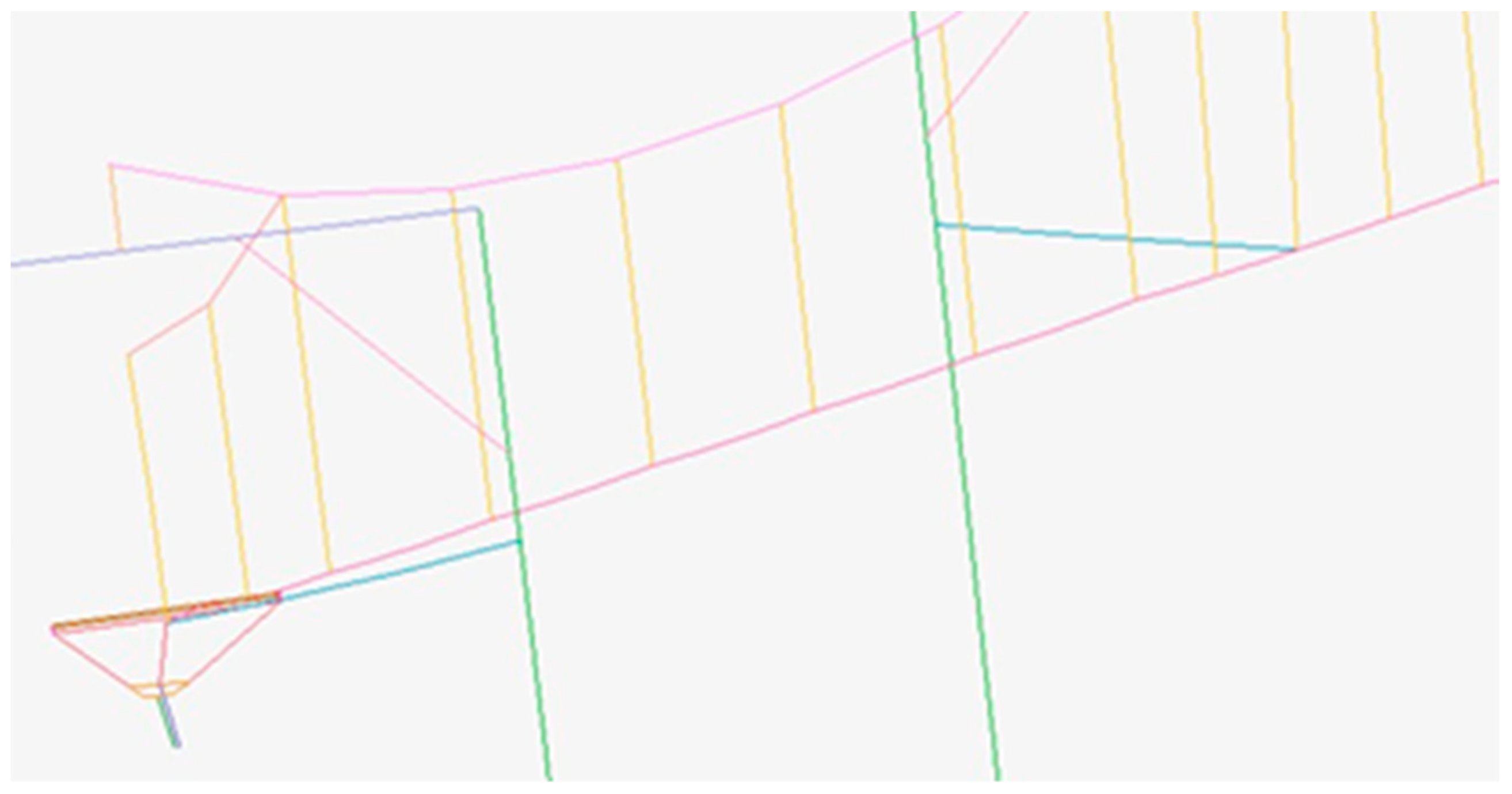
Article

Dynamic Performance Simulation and Stable Current Collection Analysis of a Pantograph Catenary System for Trolley Wire Overhead Electrically Actuated LHD

1
School of Mechanical Engineering, University of Science and Technology Beijing, Beijing 100083, China
2
Beijing Construction Engineering Research Institute Co., Ltd., Beijing 100039, China
3
Beijing Anchises Technologies Co., Ltd., Beijing 100083, China
*
Author to whom correspondence should be addressed.
Energies 2020, 13(5), 1015; https://doi.org/10.3390/en13051015
Submission received: 1 January 2020 / Revised: 21 February 2020 / Accepted: 23 February 2020 / Published: 25 February 2020
(This article belongs to the Special Issue Coal Mining Sustainable Development)

Abstract

:
The pantograph catenary system plays an important role in the power performance of electric mining vehicles. A pantograph catenary system combining both a pantograph and a catenary is one of the most promising solutions. As a case study, this paper discusses the dynamic performance and the stable current collection of a pantograph catenary system for a 14 ton underground overhead wire electrical actuated load, haul, dump machine (LHD). First, based on the optimized finite element simulation process, finite element models of the pantograph system and the catenary system are established. Second, the motion equation of the catenary is improved, and the finite element model of the pantograph catenary system is established. Finally, a dynamic simulation experiment is performed to determine the dynamic performance of the pantograph catenary system. The results show that when the radius of the contact wire is set to 0.00564 m and the tension of contact wire is set to 30 KN, the current collection indexes of the pantograph catenary system meet the requirements of stable current collection and are superior to the simulation results of related references. Therefore, the validity of the finite element model is verified; thus, the pantograph catenary system can stably charge and supply energy for the trolley wire overhead electrically actuated LHD and ensure sufficient power.

Graphical Abstract

1. Introduction

With the rapid development of society and the economy, the demand for mineral resources has increased sharply. The mining of resources has gradually shifted from surface to large-scale deep underground mining, and underground mining has brought higher requirements for the power performance and working efficiency of mining equipment. The load, haul, dump machine (LHD), which directly determines the modern mining technology level and production capacity of the mining work, is a key piece of equipment for trackless mining in underground mines. However, traditional scrapers use diesel engines for power [1]. Due to the large amount of energy consumption, closed working environment, and limited ventilation conditions, the emissions of carbon dioxide and nitrogen oxides produced by the traditional fuel LHD can cause great damage to the underground environment and human health [2,3,4].
In recent years, with the promotion of the concept of sustainable development and the improvement of environmental protection awareness, the traditional fuel scrapers have been gradually replaced by the electrically actuated LHD [5,6]. However, the poor power performance of electrically actuated LHD and the lack of continuous power for short working hours have limited their application. Therefore, a pantograph catenary system must be developed to charge and power the electrically actuated LHD to ensure that the power of the electrically actuated LHD is sufficient and sustainable. Then, the power performance of the electrically actuated LHD must be improved, to improve the mining efficiency and produce economic benefits with the electrically actuated LHD.
At present, the scheme for charging and supplying power to an electrically actuated LHD is mainly done through a towing cable system and trolley wire overhead electric supply system. The performance of the power supply system will directly affect the power performance of the electrically actuated LHD [7,8]. Bu Qing Feng et al. [9] analyzed the towing cable system of the electrically actuated LHD model TORO1400E. The closed-loop control of Programmable Logic Controller (PLC) is used to synchronize the coiled wire and the vehicle speed to achieve efficient and safe operation of the electrically actuated LHD.
Yue Hongbo [10] carried out a comparative analysis of three types of cable guide for electrically actuated LHD, introduced the structural characteristics of three types of cable guide, and analyzed the advantages, disadvantages, and development trend of cable guides for different structures. Xu Yan et al. [11] conducted a comparative study on the control strategies of the cable winding device of the electrically actuated LHD. Sui Furen et al. [12] analyzed and compared the two electric cable reeling systems of the Sandvik electrically actuated LHD and combined practical experience with the technical transformation of the cable reeling system to avoid the problems that exist in actual use.
Trolley wire overhead electric supply systems have also been studied. Li Qingyu et al. [13] studied the DC power supply between the pantograph and the overhead wire. Zhou Ying [14] studied the DC power supply protection system of trolley wire overhead electric locomotives for mining, which ensures the safe and stable operation of trolley wire overhead electric locomotives, provides technical support for similar mining equipment, and yields good social benefits. Wu Baolong [15] studied the application of variable frequency speed regulation technology in trolley wire overhead electric locomotives for mining.
However, the towing cable system of the electrically actuated LHD studied in the above literature has not been popular, which has limited the mobility and the running distance range of the electrically actuated LHD. At the same time, in the research of trolley wire overhead electric supply systems, the contact force and lifting amount between the pantograph and contact line are not calculated and analyzed, and no relevant literature was found that studied the dynamic characteristics and stable current collection between a pantograph and catenary of the trolley wire overhead electric LHD.
The trolley wire overhead electric supply system is a safe and reliable way to supply power to the electric LHD. The trolley wire overhead electric LHD is especially suitable for the long-distance transportation of mineral materials in a fixed working place. However, due to the laying technology of the trolley wire overhead, the quality requirements of the roadway top and the road surface are high, and the maintenance of the trolley wire overhead at the roadway top is not convenient. The towed cable electric LHD has limited carrying cables and can only work for short distances; thus, research and development of the trolley wire overhead electric LHD for long-distance transportation is of particular value.
Due to the complexity of mining operation conditions, there are higher requirements for the power and mobility of the electrically actuated LHD. The towing cable electrically actuated LHD is shown in Figure 1 [16]. As the cable always bears a large tensile force, the service life of the cable is short; at the same time, the transportation distance of the electric LHD is limited by the length of the cable, which limits the mobility and running distance of the electric LHD. However, extra time is needed for wiring, disconnecting, handling, and cable assembly design and repair [17], thus reducing the performance of the towed cable electrically actuated LHD. If the electric LHD is powered by overhead wires, like the mine electric trolley, the electric energy will be introduced into the electric LHD through the pantograph head slide plate. The electric motor drives the electric LHD to work, which can not only increase the haul distance of the electric LHD and reduce the cable loss but can also simplify the cable winding mechanism of the electric LHD and improve the operability and mobility of the electric LHD. According to our actual design parameters, a three-dimensional model of the trolley wire overhead electric supply system was established using the finite element method [18] to allow the lifting amount and the contact force between the pantograph and the catenary to be accurately calculated and analyzed.
Therefore, this paper focuses on the 14 ton trolley wire overhead electrically actuated LHD designed by our laboratory group as an example. According to the relevant design parameters, the finite element models of the pantograph system and the catenary system are established by using the advanced nonlinear finite element software Marc. The finite element model of the pantograph catenary system of the trolley wire overhead electrically actuated LHD is established through contact.
Our main contributions are in the following three areas: (1) the scheme, where the trolley wire overhead electric supply system is used as the pantograph catenary system of the 14 ton electrically actuated LHD to charge and supply energy, is put forward; (2) we optimize and subdivide the finite element simulation process of the pantograph catenary system, improve the motion equations of the contact wire and bearing cable, and establish the finite element model of the pantograph catenary system of trolley wire overhead electrically actuated LHD; and (3) the stable current collection performance of the pantograph catenary system of the trolley wire overhead electrically actuated LHD is analyzed.
The main contents of this paper are as follows: The second section introduces the current collection principle of the pantograph catenary system of the electrically actuated LHD and optimizes the finite element simulation process of the pantograph catenary system. In Section 3, the finite element model of the pantograph catenary system of the trolley wire overhead electrically actuated LHD is established. First, the structure and geometry of the pantograph system are introduced, and the finite element model of the pantograph system is established. Secondly, the structure of the catenary system is introduced, and the components of the catenary system are simulated as Euler Bernoulli straight beams. The kinematics equations of the contact wire and bearing cable are improved, and the finite element model of the catenary system is established. Finally, the bowhead of the pantograph and the contact wire of the catenary are set as a beam-to-beam contact, thereby establishing the finite element coupling model of the pantograph system and the catenary system.
In Section 4, under the condition that the running speed of the trolley wire overhead electrically actuated LHD is constant and that other parameters of the pantograph and the catenary are unchanged, the characteristics of the pantograph catenary system are simulated under different contact wire radii and different contact wire tensions, and the stable current collection of the charging and the energy supply of the trolley wire overhead electrically actuated LHD through the pantograph catenary system are analyzed. Section 5 summarizes the conclusions.

2. Current Collection Principle and Finite Element Simulation Process of the Pantograph Catenary System of Trolley Wire Overhead Electrically Actuated LHD

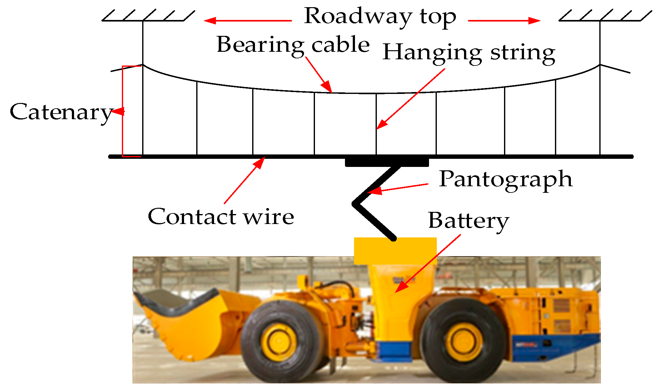
The current collection for the pantograph catenary system of the trolley wire overhead electrically actuated LHD is achieved by the sliding contact between the pantograph and the catenary [19,20], as shown in Figure 2. When the trolley wire overhead electrically actuated LHD operates to collect current, the random vibrations between the pantograph and the catenary have a great impact on the catenary. To avoid offline situations and sparks between the pantograph and the catenary, the contact force should not be too small, and the contact force should not be too large, as this will cause excessive wear between the pantograph and the catenary [21,22,23]. Therefore, it is necessary to study the contact state between the pantograph and catenary [24,25,26]. However, due to the high cost of conducting physical field tests, one of the effective ways to study the contact state between a pantograph and catenary is to establish a three-dimensional finite element model of the pantograph catenary system by using the finite element method for calculation and simulation analysis [27,28,29].
In this study, according to the actual design parameters, the finite element models of the pantograph system and the catenary system were established using the advanced nonlinear finite element software MARC. The dynamic performance of the pantograph catenary system of trolley wire overhead electrically actuated LHD was simulated and analyzed. The finite element simulation process presented in [30,31] was subdivided and optimized to improve the calculation accuracy and efficiency to obtain the finite element simulation process of the pantograph catenary system of the trolley wire overhead electrically actuated LHD, as shown in Figure 3.

3. Finite Element Modeling of the Pantograph Catenary System

3.1. A Finite Element Model of the Pantograph in the Pantograph Catenary System

The pantograph system is a very complicated spatial structure composed of an upper frame, lower frame, pushrod, balance rod, base, bowhead, skateboard, and other components [32,33,34]. Figure 4 shows the single-arm pantograph and its geometric structure. The structural requirements of the pantograph system are different for different applications and different operating speeds. The actual pantograph system includes many parts, such as rods, hinges, and other parts; therefore, it is very difficult to establish a three-dimensional model that fully reflects the structure of the actual pantograph system [35].
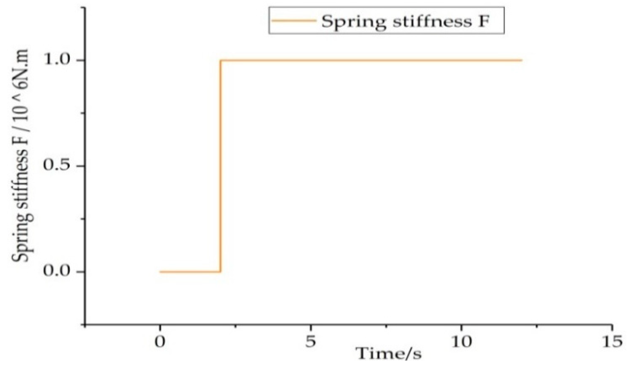
When establishing a three-dimensional finite element model of the pantograph system, we simplified the actual pantograph system accordingly. We ignored certain fine structures of the pantograph system and simplified them as equivalent components with a certain quality and elasticity [36,37,38]. This model is more intuitive and more accurate than the model established by the reduction quality method that has been used in previous studies [39]. The simplified pantograph system is mainly composed of a pushrod and frame, upper frame, bowhead, and slide plate; these three parts are connected through a hinge and a nonlinear spring [40]. The hinge and the nonlinear spring only allow relative rotation of the connecting parts along the x-axis direction. The slide plate on the pantograph head is pushed along the end of the pushrod in the negative z-axis direction. Once the slide plate reaches the final position, the hinge locks itself immediately. We realized the self-locking function through a spring stiffness value function about time, as shown in Figure 5.
When the pantograph head is raised, the spring stiffness value is 0. Once the pantograph head reaches the final position, the spring stiffness value is set to 106 [41]. Considering that the pantograph system is mainly composed of rods, a straight beam element was used to simulate each part of the pantograph system. For the simulation, the finite element model of the pantograph system had 20 straight beam elements and two shell elements. The geometric parameters and material properties of the main components in the finite element model of the pantograph system are shown in Table 1. The finite element model of the pantograph system, established by the advanced nonlinear finite element simulation software Marc, is shown in Figure 6.

3.2. Finite Element Model of the Catenary System in the Pantograph Catenary System

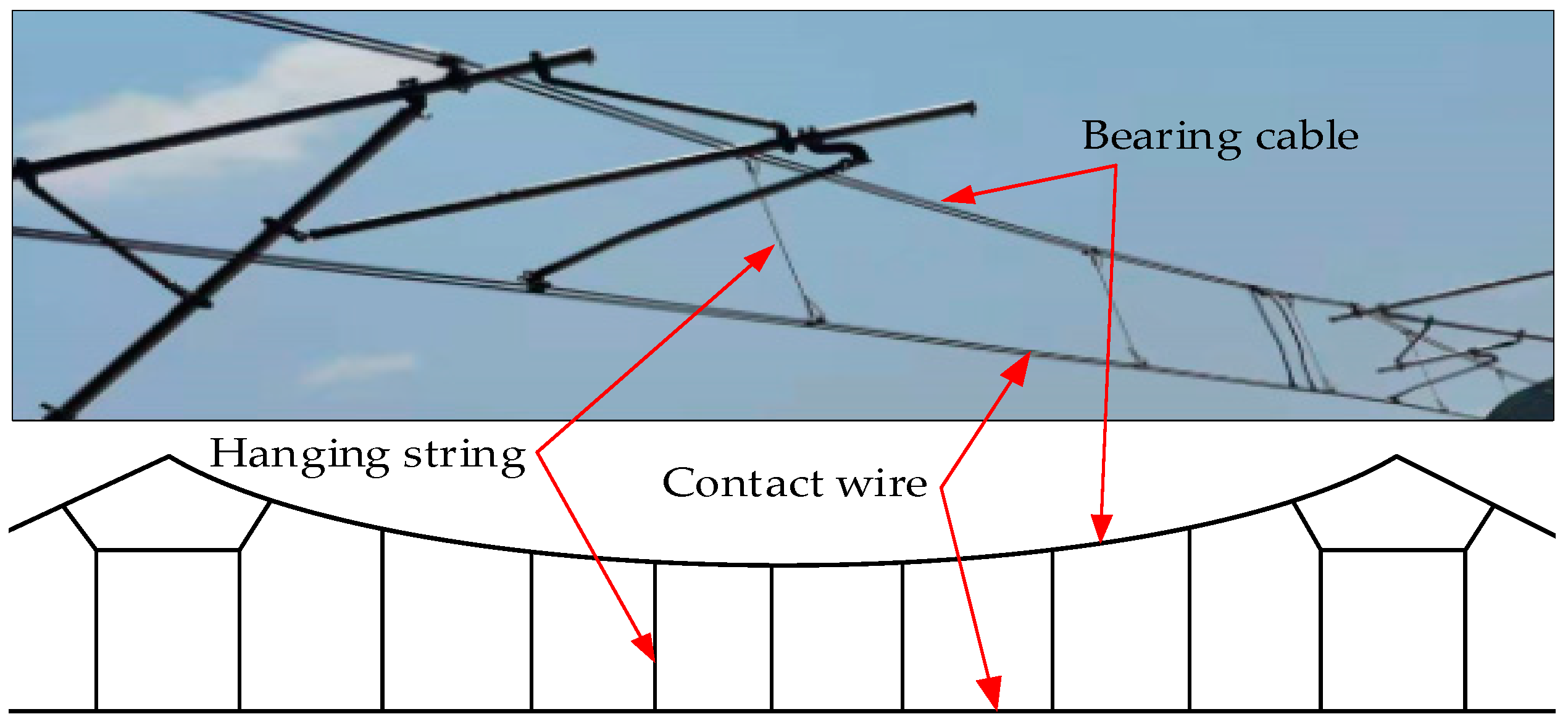
The catenary system is mainly composed of a contact wire, bearing cable, hanging string, fixed device, and a pillar [42]. In Figure 7, we show a simple chain suspension catenary and its structure [43]. We established a finite element model of a simple chain suspension catenary system. In the modelling process, the problem of neglecting the transverse vibration of a catenary in reference [44] was supplemented, and the following approximate assumptions were made:
(1) The contact wire, bearing cable, hanging string, fixing device, and pillar are equivalent to Euler Bernoulli straight beams, and the equivalent mass is evenly distributed on the catenary model unit;
(2) We considered the vertical vibration and lateral vibration of the catenary system at the same time.
We used Euler Bernoulli straight beams to approximate the components of the catenary system. In this paper, the motion equation of the catenary presented in [45,46] was improved without considering the impact force of the positioning device to obtain the motion equation of the contact wire (1) and the motion equation of the bearing cable (2), which adapts to the complexity of the running road conditions of the trolley wire overhead electrically actuated LHD.
m c 2 u c t 2 + 2 x 2 ( E I c 2 u c x 2 ) x ( T c u m x ) + K d ( u m u c ) ( x x n ) + K s u m ( x x s ) = P δ ( x V t )
m m 2 u m t 2 + 2 x 2 ( E I m 2 u m x 2 ) x ( T m u m x ) + K d ( u m u c ) δ ( x x n ) + K s u m ( x x s ) δ ( x x n ) = 0
In these formulas, E I c is the bending stiffness of the contact wire, T c is the tension of the contact wire, m c is the unit mass of the contact wire, u c is the displacement of the contact wire; E I m is the bending stiffness of the bearing cable, T m is the tension of the bearing cable, m m is the unit mass of the bearing cable, u m is the displacement of the bearing cable; δ is the impact function, K d is the stiffness of the hanging string, K s is the equivalent stiffness of the positioning device, P is the contact force between the pantograph and the catenary, x is the position of the scraper, x m is the distance of the hanging string from the moving point, x n is the distance from the positioning point to the moving point, and x s is the displacement at the positioning.
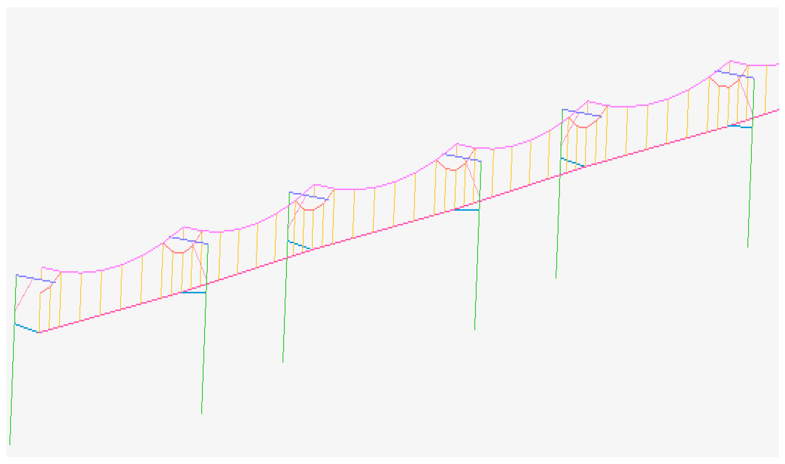
We used the advanced nonlinear finite element simulation software Marc to build a finite element model of a catenary system with a length of 25 m, six spans, and seven pillars, in which the span was 4.2 m, the distance between the suspension strings was 0.6 m, and the pull-out value of the bearing cable and the contact wire through the erection of the pillars was 300 mm. To ensure the accuracy of the simulation, the contact wire model was meshed in detail, while other elements of the catenary system were roughly meshed to improve the efficiency of the simulation. The divided finite element model of the catenary system has a total of 430 straight beam elements, each of which has 12 degrees of freedom. The gravity of the catenary system was applied to the divided finite element. The geometric parameters and material properties of the main components in the finite element model of the catenary system are shown in Table 2. The finite element model of the catenary system of the pantograph catenary system for the trolley wire overhead electrically actuated LHD is shown in Figure 8.

3.3. The Finite Element Model of the Pantograph Catenary System

In the pantograph catenary system of the trolley wire overhead electrically actuated LHD, the pantograph system and the catenary system are coupled as a whole model through contact. The contact wire and the pantograph head slide plate are set as the elastic contact body and rigid contact body, respectively, both of which are regarded as horizontal beam elements. That is, the boundary condition is set as a beam–beam contact [47]. The established finite element model of the pantograph catenary system for the trolley wire overhead electrically actuated LHD is shown in Figure 9.
The pantograph catenary system of trolley wire overhead electrically actuated LHD is charged and powered by both the pantograph system and the catenary system. The operation process of the pantograph system and catenary system generally includes three load cases [48]: (1) Apply tension to the contact wire and the bearing cable, and apply gravity to the finite element units of the pantograph system and the catenary system; six of the seven pillars can move freely in the operation direction of the pantograph and are limited in the degrees of freedom in other directions; (2) push the lower end of the pushrod in the direction opposite to the operation of the pantograph to raise the pantograph bowhead and contact the catenary; and (3) the pantograph runs a distance of 25 m along the catenary.

4. Simulation Experiment and Results Comparison Analysis

According to our design parameters, under the condition that the running speed of the trolley wire overhead electrically actuated LHD is kept constant and the other parameters of the pantograph and the catenary are unchanged, simulation experiments were carried out to analyze the characteristics and the stable current collection of the pantograph catenary system of the electrically actuated LHD under different contact wire radii and different contact wire tensions.

4.1. Analysis of the Influence of the Contact Wire Radius on the Stable Current Collection of the Pantograph Catenary System

Trolley wire overhead electrically actuated LHDs obtain their current through direct contact between the pantograph head slide plate and the contact wire in the pantograph catenary system, which then provides the power. Therefore, changing the contact wire section radius has a key influence on what is needed for sufficient power with the stable current collection of the pantograph catenary system.
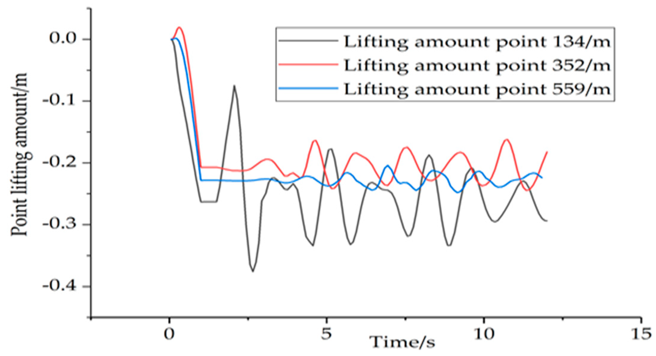
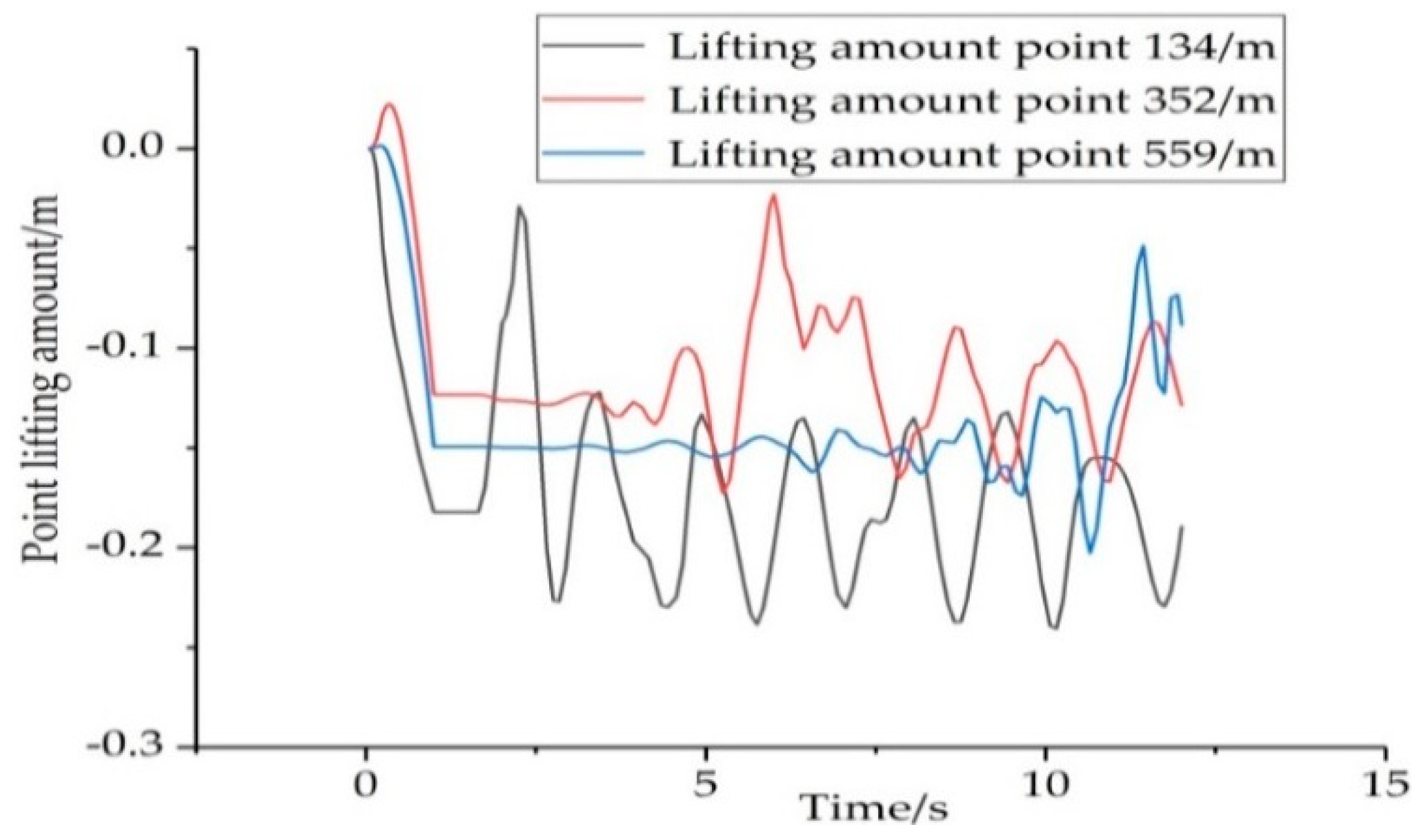
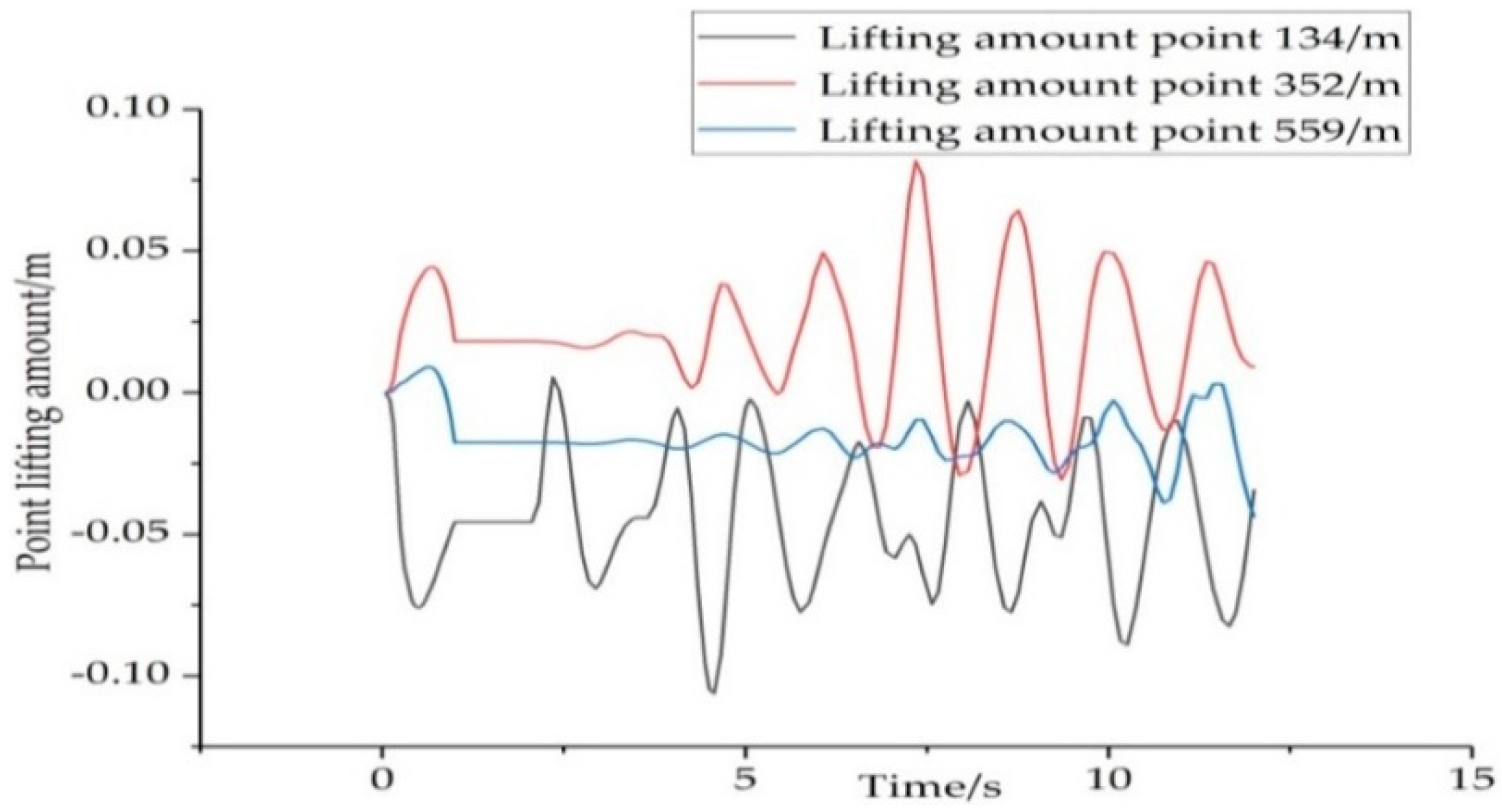
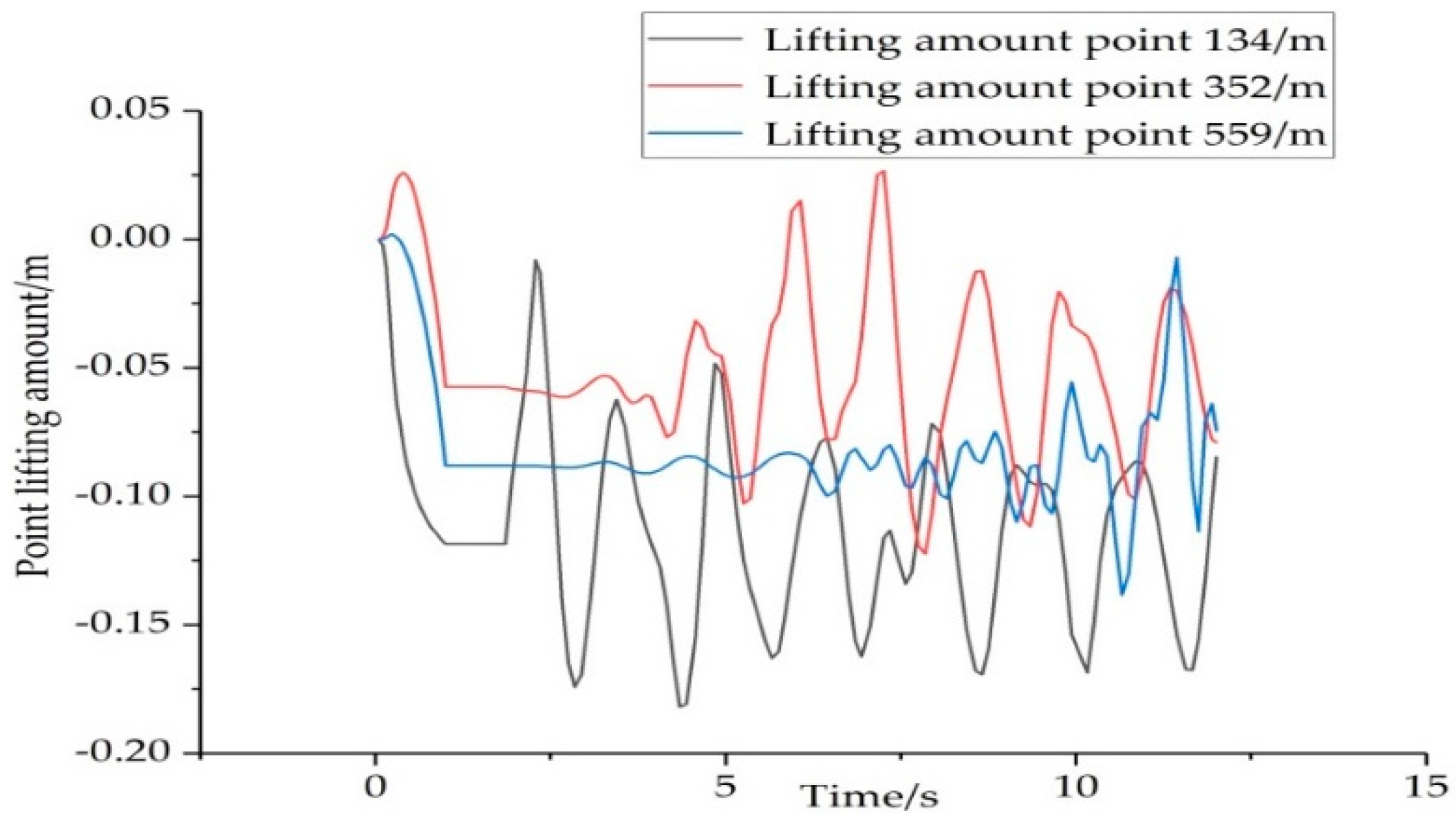
In this paper, based on the finite element model of the pantograph catenary system of the trolley wire overhead electrically actuated LHD, as established above, under the condition that the running speed of the trolley wire overhead electrically actuated LHD is kept constant and other parameters of the pantograph and the catenary are unchanged, a simulation experiment was carried out on the changes in the lifting amount of the catenary at three different points under different section radii of the contact wire. Then, the stable current collection of the pantograph catenary system was analyzed. At present, the maximum contact wire section radius specified in the European standard EN50318 [49] and used in the field is 0.00691 m. In this paper, we chose four different contact wire section radii, 0.00691, 0.00618, 0.00564, and 0.00505 m, to simulate the stable current collection of the pantograph catenary system of the trolley wire overhead electrically actuated LHD and selected the second, fourth, and sixth points among the seven points on the catenary as representatives. The lifting amounts of 134, 352, and 559 for location points under different contact wire section radii were extracted, and the curves were plotted. The changes are shown in Figure 10, Figure 11, Figure 12 and Figure 13:
We used the unique extraction function of the simulation data in Marc software to carry out statistical calculations and analysis for all specific data in the above simulation result graphs under different conditions, as shown in Table 3.
According to the analysis data in Table 3, we can conclude that with a decrease in the section radius of the contact wire, the lifting amount value of each location point shows a decreasing trend overall; the maximum value of the lifting amount is 0.08259 m less than the maximum value of the lifting amount in reference [50]—0.08700 m. According to the European standard, EN50318, the reference range of the lifting amount that meets the stable current collection is 0–0.2 m. When the contact wire section radius is set as 0.00505 m, the minimum and the maximum lifting amounts (minimum, maximum) of the three location points (points 134, 352, and 559) are (0.10470, 0.18359) m, (0.05741, 0.12300) m, and (0.07636, 0.13881) m. When the contact wire section radius is set as 0.00564 m, the minimum and the maximum lifting amounts (minimum, maximum) of the three location points (points 134, 352, 559) are (0.03970, 0.10695) m, (0.01063, 0.08209) m, and (0.00913, 0.04371) m.
Therefore, the lifting amounts of the three location points are within the reference range, 0–0.2 m, but the maximum value of the lifting amount at each point when the contact wire section radius is 0.00564 m is smaller than when the contact wire section radius is 0.00505 m, so the fluctuation of the catenary is more stable, and the stable current collection of the catenary is better. When the section radii of the contact wire are 0.00618 m and 0.00691 m, respectively, the amplitudes of the lifting amounts of the three location points are in a large range, including (0.07681, 0.23830) m, (0.03413, 0.16807) m, (0.03286, 0.20266) m, (0.00204, 0.37602) m, (0.09715, 0.24479) m, and (0.08873, 0.24816) m. We can see that when the radius of the contact wire is large, the maximum value of the lifting amount of each locating point exceeds the maximum value of the reference range by 0.2 m; thus, the catenary has large fluctuations and the stable current collection is poor.
From the data in Figure 10, Figure 11, Figure 12 and Figure 13 and Table 3, we can conclude that, under the finite element model parameters of the pantograph catenary system of the trolley wire overhead electrically actuated LHD established in this paper, when the section radius of the contact wire is set to 0.00564 m, the lifting amount is within the standard reference range, the fluctuation of the catenary is small, and the stable current collection of the pantograph catenary system is effective.

4.2. Analysis of the Influence of Contact Wire Tension on the Stable Current Collection of the Pantograph Catenary System

Under the condition of keeping the section radius of the contact wire unchanged at 0.00564 m, increasing the tension of the contact wire properly is a favorable measure to improve the stable current collection of the pantograph catenary system [51]. Generally, increasing the tension will reduce the elasticity of the catenary, increase the wave propagation speed of the contact wire, and then improve the operation speed of the electrically actuated LHD. However, in some cases, an excessive increase in the tension of the catenary, especially the tension on the bearing cable, will make the elasticity of the catenary worse [52].
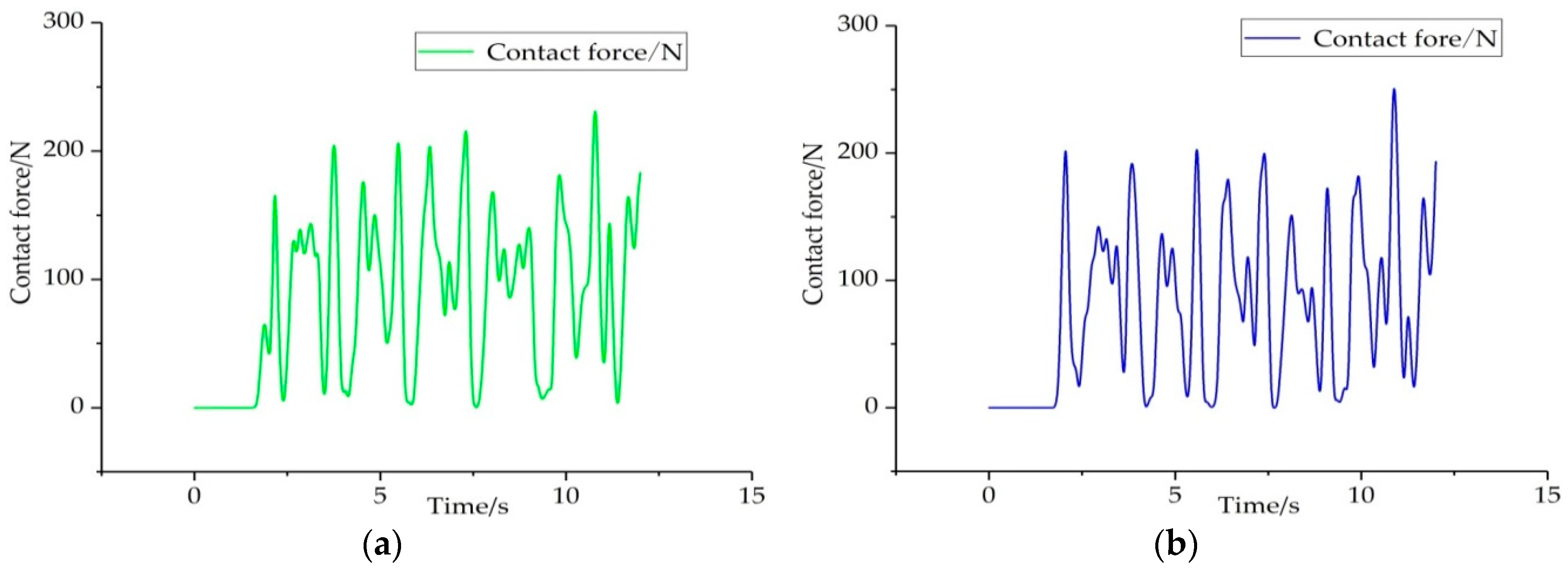
Therefore, to analyze the influence of the tension of the contact wire on the stable current collection, based on the finite element model of the pantograph catenary system established above and keeping other parameters unchanged, the tension value of the fixed catenary was set at 21 N, and the changes of contact force between the pantograph and the catenary under different contact wire tensions were calculated. According to the change in the contact force, the stable current collection index of the pantograph catenary system of the trolley wire overhead electrically actuated LHD was analyzed and calculated. We selected six different contact wire tension values of 29, 30, 31, 32, 33, and 34 KN to simulate the change in contact force between the pantograph and catenary. The simulation results are shown in Figure 14, Figure 15 and Figure 16.
From the above contact force graphs, Figure 14, Figure 15 and Figure 16, it can be concluded that as the tension of the contact wire increases, the contact force between the pantograph and the catenary changes drastically, and the offline rate also increases; however, the maximum value does not exceed the maximum value of 250 N specified in standard EN50318. We used the unique data extraction function of the Marc software to provide statistics on the offline situation between the pantograph and the catenary. The offline situation indicated that the contact force between the pantograph and catenary is 0. The offline rate was calculated based on the offline time, as shown in Table 4.
From the statistical data shown in Table 4 above, it can be concluded that under the condition of keeping the tension of the bearing cable and other parameters of the pantograph and catenary unchanged, different contact wire tensions have a great influence on the offline situation between the pantograph and catenary. With an increase in the contact wire tension, the offline time between the pantograph and the catenary gradually increases. When the contact wire tension is set to 30 KN, the corresponding offline time is T = 0.0625 s < 0.1 s and the offline rate is S = 5.21% < 10%, which meets the European standard EN50318 and China’s specified reference range for the maximum offline time (T < 0.1 s) and offline rate (S < 10%). When the contact wire tension is set to 31, 32, 33, and 34 KN, it can be seen from Table 4 that the offline time and offline rate gradually increase. At 31 KN, the offline time, T = 0.2938 s, does not satisfy the reference range (T < 0.1 s). When the contact force tension is set to 29 KN, the offline time is T = 0.1562 s and the offline rate is S = 10.4%, which does not meet the reference range (T < 0.1 s, S < 10%).
In conclusion, when the tension of the contact wire is set at 30 KN, the offline situation between the pantograph and catenary is ideal. However, with an increase in contact wire tension, the offline situation between the pantograph and catenary will become more and more serious. It can be seen from the table that both the maximum offline time and offline rate are far beyond the standard reference range (T < 0.1 s, S < 10%), which will seriously affect the stable current collection of the pantograph catenary system, and the trolley wire overhead electrically actuated LHD will not be able to be charged and supplied in time to provide sufficient power. Then, this will affect the production efficiency and related economic benefits of mining operations.

5. Conclusions

Aiming at resolving the problems of insufficient power and discontinuity of the electrically actuated LHD, a pantograph catenary system was proposed to charge and supply energy to a 14 ton underground trolley wire overhead electrically actuated LHD. To accurately analyze the stable current collection of the pantograph catenary system, we subdivided and optimized a finite element simulation process of the pantograph catenary system to improve the calculation accuracy and efficiency. Three-dimensional finite element models of the pantograph system, catenary system, and pantograph catenary system were established by using the advanced nonlinear finite element software Marc. As the pantograph system is mainly composed of rods, the straight beam unit was used to simulate the parts of the pantograph system, and the parts were connected by hinges and nonlinear springs. Similarly, all parts of the catenary system were modelled as Euler Bernoulli straight beams, and the problems of the equation of motion of the catenary, without considering the impact force of the positioning device, were improved.
Under the condition that the running speed for the trolley wire overhead electrically actuated LHD is constant and other parameters of the pantograph and the catenary are unchanged, simulation experiments of the stable current collection of the pantograph catenary system under different contact wire radii and different contact wire tensions were carried out. The results show that the lifting amount and offline rate meet the standard reference range requirements, which verifies the validity and correctness of the finite element model.
The important findings are summarized as follows:
(1) The finite element simulation process of the pantograph catenary system of the trolley wire overhead electrically actuated LHD was optimized and subdivided, and the motion equations of the contact wire and the bearing cable were improved, so that the efficiency of the simulation calculation and the accuracy of the results were improved. The lifting amount and offline rate were completely within the standard reference range.
(2) With the decrease of the section radius of the contact wire, the maximum value of the lifting amount of each location point showed a decreasing trend. When the contact wire section radius was set to 0.00564 m, the lifting amount of each positioning point was within the EN50318 standard reference range 0–0.2 m, the fluctuation of the catenary was small, and the stable current collection of the pantograph catenary system was good.
(3) Under the condition of keeping the tension of the bearing cable and other parameters of the pantograph and the catenary unchanged, the offline time between the pantograph and the catenary gradually increased with the increase in the tension of the contact wire. When the tension of the contact wire was set to 30 KN, the corresponding offline time was T = 0.0625 s < 0.1 s and the offline rate was S = 5.21% < 10%, which are both within the reference range of the European standard, EN50318 and the Chinese standard for offline time (T < 0.1 s) and offline rate (S < 10%), thereby meeting the requirements for stable current collection of a pantograph catenary system.
(4) The research results of this paper provide a theoretical reference for the next step of field construction and testing of the stable current collection of the 14 ton underground trolley wire overhead electrically actuated LHD through a pantograph catenary system. It is of reference value to further promote the rapid development of new energy engineering machinery.
From an energy perspective, we make the following contributions. On the one hand, we further promote the application of sustainable energy electricity in new energy engineering machinery. The pantograph catenary system composed of a pantograph and catenary is used to charge and power a 14 ton underground trolley wire overhead electrically actuated LHD, thereby ensuring the power adequacy and continuity of the electrically actuated LHD. On the other hand, traditional fuel scrapers produce a lot of pollution and noise. At the same time, the towed cable electrically actuated LHD has poor mobility and a limited running distance. The trolley wire overhead electrically actuated LHD not only achieves zero emissions, low pollution, and low noise, it also has good mobility and an unlimited running distance.

Author Contributions

Conceptualization, Y.L., T.J. and K.Y.; methodology, Y.L., T.J.; software, Y.L., K.Y.; validation, Y.L., T.J.; investigation, Y.L., K.Y.; writing—original draft preparation, Y.L.; writing—review and editing, T.J., L.L.; supervision, L.L.; project administration, T.J., L.L.; funding acquisition, L.L., T.J. All authors have read and agreed to the published version of the manuscript.

Funding

This research was funded by the National Key Research and Development Program of China, grant number 2018YFE9102900. Scientific Research Fund Subsidized Project of BGRIMM Technology Group, grant number JTKJ1827.

Conflicts of Interest

The authors declare no conflict of interest. The funders had no role in the design of the study; in the collection, analyses, or interpretation of data; in the writing of the manuscript, or in the decision to publish the results.

Nomenclature

L1Lower arm AD and length
L2The length of DQ on the upper frame
L3The length of CD on the upper frame
L4The length of BC
L5The length between AE
L6The length of balance bar EF
L7The length of the bow QF
aThe longitudinal distance between the two points A and B
bThe lateral distance between the two points A and B
cThe angle between DQ and CD
gThe angle between AE and AD
E I c The bending stiffness of the contact wire
T c The tension of the contact wire
m c The unit mass of the contact wire
u c The displacement of the contact wire
E I m The bending stiffness of the bearing cable
T m The tension of the bearing cable
m m The unit mass of the bearing cable
u m The displacement of the bearing cable
δ The impact function
K d The stiffness of the hanging string
K s The equivalent stiffness of the positioning device
P The contact force between pantograph and catenary
x The position of the scraper
x m The distance of the hanging string from the moving point
x n The distance from the positioning point to the moving point
x s The displacement at the positioning
TOffline time between pantograph and catenary
SOffline rate between pantograph and catenary

References

  1. Su, X.J. Application and Development of LHDs in China. MIining Res. Dev. 2006, 26, 89–92. [Google Scholar] [CrossRef]
  2. Machedon-Pisu, M.; Borza, P. Are Personal Electric Vehicles Sustainable? A Hybrid E-Bike Case Study. Sustainability 2020, 12, 23. [Google Scholar] [CrossRef] [Green Version]
  3. Turoń, K.; Kubik, A.; Chen, F. Operational Aspects of Electric Vehicles from Car-Sharing Systems. Energies 2019, 12, 4614. [Google Scholar] [CrossRef] [Green Version]
  4. Kaboli, A.; Carmichael, D. Optimum scraper load time and fleet size for minimum emissions. Int. J. Constr. Manag. 2014, 14, 209–226. [Google Scholar] [CrossRef]
  5. Wei, S.G.; Bian, R.L. Development and Application of Jin-0.4 Electric LHD. Metal Mine. 2003, 23, 42–43. [Google Scholar] [CrossRef]
  6. Wang, J.Y. Discussion on the feasibility of using of electric LHD in Tieshan Mine. Nonferrous Met. 2016, 68, 21–23. [Google Scholar]
  7. Li, H.Z. Improvement of Cable Roller Support for WJD-0.75 Electric Scraper. Copper Eng. 2018, 6, 87–88, 101. [Google Scholar] [CrossRef]
  8. Chang, L.X. Research on Match of Driveline of Electrically Actuated LHD. Master’s Thesis, Lanzhou University of Technology, Lanzhou, China, 2012. [Google Scholar]
  9. Bu, Q.F.; Shi, G.L. TORO1400E Electric LHD Cable Reeling System Analysis. Coal Mine Mach. 2015, 36, 53–54. [Google Scholar] [CrossRef]
  10. Yue, H.B. Comparisons of Three Types of Rolling Cable Guide Devices for Electrically Actuated LHD. Min. Mach. 2014, 42, 139–141. [Google Scholar] [CrossRef]
  11. Xu, Y.; Zhang, W.X. The control strategy research of the electric LHD’s roll-cable devise. Mach. Des. 2005, 24, 24–26. [Google Scholar] [CrossRef]
  12. Sui, F.R. Research and Improvement on Warping System of Sandvik Electrical Scraper. Mech. Eng. Autom. 2018, 4, 122–123. [Google Scholar] [CrossRef]
  13. Li, Q.Y.; Qin, H.B. Research and Design of a Trolley Type Electric Scraper. Constr. Mach. Equip. 2007, 38, 24–28. [Google Scholar] [CrossRef]
  14. Zhou, Y. Research on Power Supply Protection System of Direct Current Trolley in Mining Electric Locomotive. Shanxi Coking Coal Sci. Technol. 2015, 1, 21–24. [Google Scholar] [CrossRef]
  15. Wu, B.L. Study on Application of frequency control technology in mine trolley locomotive. Shandong Coal Sci. Technol. 2015, 7, 91–92. [Google Scholar] [CrossRef]
  16. Han, Y.Y.; Zhang, Z.G.; Zhu, K.G. An Improved Design of the Cable Arrangement Device for the Electric Scooptram. J. Liaoning Inst. Sci. Technol. 2016, 18, 20–22. [Google Scholar] [CrossRef]
  17. Wu, J.B. Structural design of flexible cable winding device of the electrically actuated LHD. Nonferrous Met. 2000, 5, 29–32. [Google Scholar] [CrossRef]
  18. Yao, R.; Huang, X.B. Analysis of Finite Element Modeling of Overhead Conductor. Sci. Technol. Inf. 2013, 24, 103–104. [Google Scholar] [CrossRef]
  19. Liu, W.X.; Liu, Y.C.; Niu, S.Y.; Liu, Z.Q. Assessment Method for Substation Capacity Credit of Generalized Power Source Considering Grid Structure. Sustainability 2017, 9, 928. [Google Scholar] [CrossRef] [Green Version]
  20. Chen, Z.H.; Shi, Y.L.; Shi, G.; Wang, Z.Y.; Kang, L.Q. Calculation Model of the Contact resistance between Pantograph Slide and Contact Wire. Trans. China Electrotech. Soc. 2013, 28, 188–195. [Google Scholar] [CrossRef]
  21. Wu, G.; Gao, G.; Wei, W.; Yang, Z. Electrical Contact of Pantograph and Catenary System. In The Electrical Contact of the Pantograph-Catenary System; Springer: Berlin/Heidelberg, Germany, 2019; Volume 4, pp. 978–981. [Google Scholar]
  22. Jung, S.; Kim, Y.; Paik, J.; Park, T. Estimation of Dynamic Contact Force Between a Pantograph and Catenary Using the Finite Element Method. J. Comput. Nonlinear Dyn. 2012, 7, 41006–41019. [Google Scholar] [CrossRef]
  23. Song, H.L.; Wu, J.Y.; Wu, Y.; Zheng, J.H.; Zheng, Q.L. Influence of Aerodynamic to High Speed Pantograph Current Collection Characteristics. Electr. Railw. 2010, 21, 28–32. [Google Scholar] [CrossRef]
  24. Rauter, F.; Pombo, J.; Ambrosio, J.; Chalansonnet, J.; Bobillot, A.; Pereira, M. Contact Model for The Pantograph-Catenary Interaction. J. Syst. Des. Dyn. 2007, 3, 447–457. [Google Scholar] [CrossRef] [Green Version]
  25. Su, Y.C. On the contradiction between catenary and pantograph. Opencast Mining Technol. 2012, 6, 55–57. [Google Scholar] [CrossRef]
  26. Kia, S.; Bartolini, F.; Mabwe, A.; Ceschi, R. Pantograph-catenary interaction model comparison. In Proceedings of the IECON 2010-36th Annual Conference on IEEE Industrial Electronics Society, Glendale, AZ, USA, 7–10 November 2010. [Google Scholar]
  27. Alberto, A.; Benet, J.; Arias, E.; Cebrian, D.; Rojo, T.; Cuartero, F. A high performance tool for the simulation of the dynamic pantograph–catenary interaction. Math. Comput. Simul. 2008, 79, 652–667. [Google Scholar] [CrossRef]
  28. Zhao, S.P.; Zhang, C.R.; Zhang, Y.P.; Wang, S.H. Influence of Partial Arc on Electric Field Distribution of Insulator Strings for Electrified Railway Catenary. Energies 2019, 12, 3295. [Google Scholar] [CrossRef] [Green Version]
  29. Guan, J.F.; Wu, J.Q. Finite element analysis of pantograph-catenary dynamic interaction. Arch. Transp. 2016, 39, 77–85. [Google Scholar] [CrossRef]
  30. Zdziebko, P.; Uhl, T. Investigations on the effects of friction modeling in finite element simulation of machining. Int. J. Mech. Sci. 2010, 52, 31–42. [Google Scholar] [CrossRef]
  31. Zhao, F. Dynamic Performance Simulation Based on a Pantograph-Catenary System of High-Speed Railway and Analysis Based on the Finite Element Method. Master’s Thesis, Southwest Jiaotong University, Chengdu, China, 2014. [Google Scholar]
  32. Zhao, F.; Liu, Z.G.; Zhang, X.X. Simulation of High-speed Pantograph-catenary System Dynamic Performance Based on Finite Element Mode. J. China Railw. Soc. 2012, 34, 33–38. [Google Scholar] [CrossRef]
  33. Zhou, S.; Zhu, Z.R.; Jia, F. Optimization design of pantograph structure parameters for subway trains. Mech. Electr. Inf. 2015, 15, 150–153. [Google Scholar] [CrossRef]
  34. Jia, H.L.; Zhao, Y.H.; Zhou, Y.M.; Song, Y. Research and Analysis of the Structural Strength of Pantograph. Railw. Locomot. Car 2018, 38, 29–31. [Google Scholar] [CrossRef]
  35. Chen, K. Study of 3D Multi-body Dynamics Model of Pantograph for Electric Locomotive. Electr. Drive Locomot. 2006, 5, 11–14. [Google Scholar] [CrossRef]
  36. Zhou, N.; Zhang, W.H.; Wang, D. Lumped Mass Model for Dynamic Performance Simulation of Pantograph. J. Southwest Jiaotong Univ. 2011, 46, 398–403. [Google Scholar] [CrossRef]
  37. Yu, S.J.; Yang, J.; Fang, Y.; Chen, X.L. On Equivalent Mass of Urban Rail Transit Vehicle’s Pantograph. Urban Mass Transit 2010, 13, 39–41. [Google Scholar] [CrossRef]
  38. Benet, J.; Cuartero, N.; Cuartero, F.; Rojo, T.; Tendero, P.; Arias, E. An advanced 3D-model for the study and simulation of the pantograph catenary system. Transp. Res. Part C Emerg. Technol. 2013, 36, 138–156. [Google Scholar] [CrossRef]
  39. Jiang, J.; Liu, Z.G.; Song, Y. Simulation Study on Dynamic Behavior of Pantograph-Catenary Considering the Nonlinear Characteristics of Pantograph. Comput. Simul. 2015, 32, 170–174. [Google Scholar] [CrossRef]
  40. Wang, W.; Sun, J.; Yu, D.Y.; Ma, X.R. Analytical model for a complex joint with the latch mechanism of space structure. J. Astronaut. 2004, 25, 1–4. [Google Scholar] [CrossRef]
  41. Lu, M.W.; Yang, X.; Lu, C. The Space Electric Connector Wave Spring Performance Analysis. Modul. Mach. Tool Autom. Manuf. Tech. 2014, 2, 150–153. [Google Scholar] [CrossRef]
  42. Sun, L.J. Analysis on Dynamic Response of Suspension System Supposed by Overhead Contact System Based on Wind Load. Railw. Stand. Des. 2010, 6, 119–121. [Google Scholar] [CrossRef]
  43. Yan, Z.S. Static Simulation of Stitched Simple Trolley-type Catenary. Railw. Transp. Econ. 2013, 35, 57–62. [Google Scholar] [CrossRef]
  44. Wu, Y. Research on Dynamic Performance and Active Control Strategy of the High-Speed Pantograph-Cate-Nary System. Ph.D. Thesis, Beijing Jiaotong University, Beijing, China, 2011. [Google Scholar]
  45. Li, F.L.; Li, M.; Tang, J.X. Differential equations of catenary’s motion influenced by gravity. J. Cent. South Univ. 2005, 36, 673–677. [Google Scholar] [CrossRef]
  46. Liu, S.B.; Wang, Y. Research on Dynamic Simulation of High-speed Pantograph-coupling System. J. East China Jiaotong Univ. 2014, 31, 68–71. [Google Scholar] [CrossRef]
  47. Liu, Y.; Duan, Z.D.; Zhou, D.C. Updating semi-rigidity of joints and boundary conditions of structures using a hybrid finite element. J. Vib. Shock 2009, 28, 39–47. [Google Scholar] [CrossRef]
  48. Wu, Y.; Wu, J.Y.; Zheng, J.H. A Simulation Study on Current Collection of High-Speed Pantograph-Cate -nary. J. Beijing Jiaotong Univ. 2009, 33, 61–64. [Google Scholar]
  49. Finner, L.; Poetsch, G.; Sarnes, B. Program for catenary–pantograph analysis, PrOSA statement of methods and validation according to EN 50318. Veh. Syst. Dyn. 2015, 53, 305–313. [Google Scholar] [CrossRef]
  50. Guo, J.B.; Yang, S.P.; Gao, G.S. Analysis on stable current-collecting of pantograph-catenary system. J. Dyn. Control. 2004, 2, 60–63. [Google Scholar] [CrossRef]
  51. Xie, Q.; Zhi, X. Wind Tunnel test of tension effects on vibration responses of the catenary system. J. Southwest Jiaotong Univ. 2018, 53, 1009–10106. [Google Scholar] [CrossRef]
  52. Zhou, D.P.; Wu, J.Y.; Wu, Y. Finite element simulation on the pantograph-catenary dynamic system for Beijing-tian jin intercity high-speed railway. J. Traffic Transp. Eng. 2009, 9, 0025–0029. [Google Scholar]
Figure 1. Towed cable electrically actuated load, haul, dump machine (LHD).
Energies 13 01015 g001
Figure 2. Schematic diagram of the current collection principle of a pantograph catenary system for a trolley wire overhead electrically actuated LHD.
Energies 13 01015 g002
Figure 3. Finite element simulation flowchart of the pantograph catenary system of trolley wire overhead electrically actuated LHD.
Energies 13 01015 g003
Figure 4. Schematic diagram of a single-arm pantograph and its geometric structure.
Energies 13 01015 g004
Figure 5. Simulation function diagram of the spring stiffness value related to time.
Energies 13 01015 g005
Figure 6. The finite element model of the pantograph system in the pantograph catenary system for trolley wire overhead electrically actuated LHD.
Energies 13 01015 g006
Figure 7. Simple chain suspension catenary and structure diagram.
Energies 13 01015 g007
Figure 8. The finite element model of the catenary system in the pantograph catenary system of trolley wire overhead electrically actuated LHD.
Energies 13 01015 g008
Figure 9. The finite element model of the pantograph catenary system for the trolley wire overhead electrically actuated LHD.
Energies 13 01015 g009
Figure 10. The lifting amount changes of three location points when the contact wire section radius is 0.00691 m.
Energies 13 01015 g010
Figure 11. The lifting amount changes of three location points when the contact wire section radius is 0.00618 m.
Energies 13 01015 g011
Figure 12. The lifting amount changes of three location points when the contact wire section radius is 0.00564 m.
Energies 13 01015 g012
Figure 13. The lifting amount changes of three location points when the contact wire section radius is 0.00505 m.
Energies 13 01015 g013
Figure 14. The change in contact force between the pantograph and catenary. (a) when the tension of the contact wires is 29; (b) when the tension of the contact wires is 30 KN.
Energies 13 01015 g014
Figure 15. The change in contact force between the pantograph and catenary. (a) when the tension of the contact wires is 31 KN; (b) when the tension of the contact wires is 32 KN.
Energies 13 01015 g015
Figure 16. The change in contact force between the pantograph and catenary. (a) when the tension of the contact wires is 33 KN; (b) when the tension of the contact wires is 34 KN.
Energies 13 01015 g016
Table 1. Geometric parameters and material characteristics of the main components of the pantograph system.
Design ParametersL1L2L3L4L5L6L7abcg
Parameter value175018002301208175018101187701400.350.017
MaterialCarbon steelAluminum alloyCarbon steelCarbon steelCar-bon steelAluminum alloyAluminum alloyN/AN/AN/AN/A
Table 2. The geometric parameters and material properties of the main components of the catenary system.
ComponentTensile Modulus/GPaPoisson’s RatioMass Density/(kg.mm−3)Section AreaMaterial
Contact wire1200.338900150AgCu110
Bearing cable1200.338900150JTMH120
Hanging string1200.33890010Copper–magnesium alloy
Locator2100.3027002700Aluminum bronze
Inclined arm2100.3078505026Corrosion resistant steel
Table 3. The lifting amounts of location points under different contact wire radii.
Contact wire Radius/mLocation PointLifting Amount MaxLifting Amount MinimumLifting Amount Average
0.00691 mpoint 1340.376020.002040.24825
point 3520.244790.097150.19841
point 559 0.248160.088730.21876
0.00618 mpoint 134 0.238300.076810.17269
point 352 0.168070.034130.11200
point 559 0.202660.032860.13963
0.00564 mpoint 134 0.106950.039700.04552
point 352 0.082090.010630.01944
point 559 0.043710.009130.01627
0.00505 mpoint 134 0.18359 0.104700.11400
point 352 0.123000.057410.05127
point 559 0.138810.076360.08259
Table 4. The offline condition between the pantograph and catenary under different contact wire tensions.
Contact Wire TensionBearing Cable Tension 21 KN
Maximum Offline Time/sOffline Rate/%
29 KN0.156210.4%
30 KN0.06255.21%
31 KN0.293818.3%
32 KN0.343819.1%
33 KN0.406328.1%
34 KN0.500035.5%