Abstract
Enhancements in heat transfer, and consequently the thermohydraulic performance of solar air heaters (SAHs), are necessary to widen and optimize their use in many applications such as solar drying or heating buildings. In this investigation, two techniques were used. A novel solar selective coating combined with broken arc ribs roughness was employed with a SAH and the evaluation of the energetic and exergetic performance was applied under four airflow working conditions compared to a smooth absorber SAH coated with the same coating. The results revealed that the Nusselt number of roughened SAH with the new coating exhibited a notable improvement compared to a smooth absorber SAH and a roughened SAH without a coating. Furthermore, the thermal efficiency increased with the increase in the air flow rate and the maximum rise was 18.8% compared to a smooth SAH. The highest increase in exergy was 51.6% with minimum values of exergy destruction and improvement potentials. In brief, the roughened SAH with 4% CNTs/CuO-black paint under the airflow rate of 0.0244 m3/s (condition C) exhibited the best energetic and exergetic performance.
1. Introduction
Solar air collectors (SAHs) are the main component of solar energy utilization systems that absorb incoming solar radiation, transforming it into thermal energy and conveying the energy to the collector’s fluid [1]. Despite the huge range of applications of SAHs such as building heating, solar dryers, and water desalination as a consequence of their simple construction, low cost, and ease to build and maintain [2], their thermal efficiency is low especially of flat-plate SAHs because of the low convective heat transfer coefficient between the air and the absorber sheet [3]; in addition, the heat losses to the surrounding environment massively rise with an increase in the absorber plate temperature, specifically under lower airflow rates that cause a lower thermal efficiency [4].
As a result of the intrinsic drawback of SAHs, which is weak thermal efficiency, the use of expanded heat transfer elements like porous and corrugated surfaces as well as finned absorbers, is a necessary solution [5]. Furthermore, other techniques have been proposed to improve the heat transfer coefficient such as different shaped baffles [6], chemical surface treatments [7], reorganizing the flow directions [8], and impinging air jets [9].
Solar selective coatings are recommended to be deposited on the surface of the SAH’s absorber for their ability to enhance the SAH’s performance [10]. Absorber spectral selectivity is identified by its high absorptance(α) in the short-wavelength band (0.3–3 μm) of the solar radiation and low emittance (ε) at the far-infrared band of the spectrum related to the blackbody thermal emittance at the operational absorber temperature, which is accomplished by solar selective coatings [7]. A novel solar selective coating was prepared and applied to a flat plate SAH, where the thermal efficiency was improved by up to 24% compared to commercial black paint [11]. AlShamaileh [12] tested black paint boosted by a 6% NiAl alloy where the thermal efficiency of the solar water heater increased and the water temperature was higher by 5 °C compared to the black paint.
Along the same vein, artificial roughness plays a significant role in enhancing the SAH’s performance by generating turbulence and reordering the airflow near the surface of the absorber (laminar sublayer), leading to a boost in the heat transfer between the airflow and heated plate [1,13]. Some artificial roughness geometries recommended by Kabeel et al. [2] included a grouping of transversal I-designed and V-up (or V-down) wire rib roughness, chamfered, circular rib, semi-circular, and grooved roughness. Furthermore, for better overall thermo-hydraulic performance, multiple arc ribs and multiple arc ribs with gaps are recommended by Singh and Singh [14].
Hans et al. [15] experimentally investigated employing broken arc ribs to the SAH, then the influence of roughness parameters such as Reynold’s number, relative ( roughness height, pitch, gap position, and gap width ) and arc angle on the Nusselt number and friction factor. The maximum increase in Nusselt number and friction factor over that of the smooth duct were 2.63 and 2.44 times, respectively. The same effect of artificial roughness on the Nusselt number and friction has been reported in many other studies [16,17,18,19,20].
Experimentally, Karmare and Tikekar [21] studied the thermo-hydraulic output of RSAHs with metallic rib grits, since then, significant changes of thermal efficiency ranging from 10 to 35% over SSAHs have been accomplished.
Bayrak et al. [22] evaluated five types of SAHs by inserting different porous baffles by means of energy and exergy analysis methods under two airflow rates. They found that a SAH with baffles of 6 mm thickness at the air mass flow of 0.025 kg/s was the highest thermal efficiency. In addition, the energy and exergy efficiency values ranged from 39.35–77.57% to 21.55–54.54%, respectively, for the five different studied collectors.
Fudholi et al. [5] developed a finned double pass SAH under a mass flow range of 0.03–0.1 kg/s. The maximum energy efficiency was about 77%, which was observed at a 0.09 kg/s mass flow rate. The finned double-pass SAH’s optical efficiency was about 70–80 %. Improvement potential ranges were 740–1070 W for exergy efficiency values from 15 to 28% under a solar radiation of 425–790 W/m2.
From the previous narrative, both solar selective coatings and artificial roughness play a significant role in improving the SAH performance; in this study, broken arc ribs were used as roughness elements according to Singh and Singh’s [14] recommendations regarding their better overall thermo-hydraulic performance. Additionally, they recommended that future work should be combined with surface enhancement techniques such as selective coatings with arched absorber plates because of the lack of these kinds of investigations.
The main aim of this study was to evaluate the energetic and exergetic performance of a SAH artificially roughened by broken arc ribs and coated with a new solar selective coating to enhance its potentials for use in building heating or drying agricultural material.
2. Materials and Methods
2.1. Coating Preparation
Carbon nanotubes (CNTs) and cupric oxide (CuO) nanoparticles that were combined as a 1:1 weight ratio were then dispersed at different mass proportions from 0 to 5% of the CNTs/CuO composite in the black paint. The solution was diluted by liquid thinner, then sonicated and stirred for about 1 hour. The solar absorptance, α, (measured by Lambda 750 S UV/VIS/NIR spectrophotometer) and thermal emittance, ε, (measured by a Fu Liye FTIR5700 spectrometer) of the small coated Al samples were calculated [23], respectively, by
Then, the spectral selectivity was calculated by the following:
As suggested by International Energy Agency (IEA) Task 27 report on solar heating and cooling [24]. The optical and morphological characterization of the new coatings have been discussed in detail in our previous study [11]. Briefly, the results showed that 4% CNTs/CuO-black paint was the best composite with solar absorptance and thermal emittance reaching 0.964 and 0.124, respectively, with the highest solar selectivity as illustrated in Figure 1.
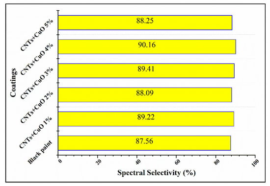
Figure 1.
Spectral selectivity of several mass percentages from 0% to 5% of Carbon Nanotubes/Cupric Oxide powder embedded in the black paint.
2.2. The Solar Air Heaters (SAHs) Installation
At the factory at the engineering college (Huazhong Agricultural Uni., Wuhan, China), two units of SAHs were built with a duct volume 0.2 m3 (2 × 1 × 0.1 m length, width, height, respectively). Double glass covers (thickness of 4 mm and a 20 mm gap in between) were used. Furthermore, the SAHs’ bottom (0.08 m thickness) and sides (0.06 m thickness) were insulated with polyurethane slabs (heat conductivity ≤0.025 W/m K).
Aluminum plates (2 mm thick) were used as absorbers, then Al ribs were used to make artificial roughness for one SAH and the other one was left with a smooth absorber. Table 1 shows the roughness geometry parameters employed in the experiment following the recommendation of Hans et al. [15] by employing broken arc ribs of Al on the surface of one absorber. The roughened and smooth absorber sheets were painted with CCu–BP using a spray method for both. A centrifugal fan from the lower side of the collector pushed the ambient air. Fully south-oriented solar air heaters were inclined 30° to the horizontal plane to maximize the incident solar radiation in the daytime, as shown in Figure 2.

Table 1.
Roughness geometry parameters employed in the experiment.
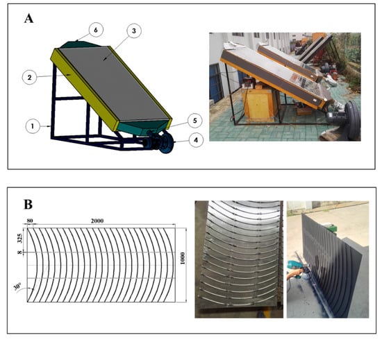
Figure 2.
(A) Schematic and photographic of SAHs: (1)collector stand, (2) Insulation material, (3) glass covers, (4) air fan, (5) air inlet, (6) air outlet; (B) Roughness arrangement and absorber plate with broken arc shape ribs.
2.3. Performance Analysis of the Flat Plate Solar Air Heaters
For the evaluation of RSAH and SSAH energetic and exegetic performances, many variables have been measured. Since the SAHs were fixed and oriented to face the south and inclined with 30° to the horizon. Next, k-type thermocouples connected to a datalogger recorded the absorber, fluid, and glass cover temperatures every three minutes. In addition, the ambient temperature and wind velocity were recorded by a weather station. At the top of the SAH, a pyranometer was fixed to measure the global solar radiation. To circulate the air across the SAHs, a centrifugal fan (TB125, 380 V, 60 Hz, 33–39 m3/min) was used and a digital anemometer (AS8556) was used to measure its discharges.
2.4. Energetic and Exergetic Performance
Energy analysis is an essential tool to understand the basic design and performance of any thermal system. The first thermodynamic energy balance law was determined by applying the measured measurements from the experiment, the thermal energy balance:
where , , and are the absorbed, useful, and lost energy, respectively. Based on Duffie and Beckman [25], the useful heat gain from the collector is:
The radiation absorbed by the absorber surface is described as:
The that implies the quantity that relates a collector’s actual useful energy gain to the useful gain if the entire collector’s surface was at the temperature of the fluid inlet.
The collector’s overall loss coefficient is the sum of the top, lower, and edges loss coefficients:
Top losses for the numerous covers:
Klein [26] produced an empirical equation for Ut that is beneficial for assessing both hand and computer calculations:
where for 0° < β < 70°; for 70° < β < 90°, use β = 70°, .
Loss of energy through the collector’s bottom is
where k is the thermal conductivity and L is the insulation thickness.
The losses within the edge should be referenced to the collector area. If the edge loss coefficient–area product is the (U/A) edge, then the edge loss coefficient, with regard to the collector area Ac, is
The thermal efficiency of the SAH according to ASHRAE is:
The heat transfer coefficient (h) for the absorber is [15]:
where the heat transfer coefficient was used to determine the Nusselt number (Nu) by using the following equation [27]:
The exergy efficiency can be written based on the Second Law of Thermodynamics as the ratio of the absorbed exergy of air divided by the exergy of solar radiation on the collector [28,29]:
The parameters of this equation are represented as [30,31]:
The Exu,p actual exergy delivered, considering pressure drop of collector fluid, is calculated by [30]:
where is the fan motor efficiency taken equal to 0.9 [30].
The input exergy (the exergy of sun radiation) is defined as:
where Ta and Tsun represent the temperatures of ambient and solar intensity. For the solar intensity temperature, 5600 K was assumed.
Van Gool [32] indicated that the optimum exergy efficiency gains for a system or process were naturally achieved by reducing exergy destruction . When evaluating different economic processes or industries, it is useful to use the idea of an “improvement opportunity” [5,29]. The improvement potential (IP) of a system or process is given by
2.5. Uncertainty Analysis
The associated independent variables quantified the relative uncertainty of thermal efficiency, and the uncertainty of thermal efficiency was obtained through the strategy of error propagation. The uncertainty in the estimation of different parameters was evaluated based on the uncertainty of all the associated independent variables in the measurement. If result R is a function of independent variables x1, x2, x3, …, xn such that [33,34]:
Then, the relative uncertainty [28,31] is
The uncertainties of mass flow rate was measured by a digital anemometer (AS8556) (air velocity from 0–45 m/s and accuracy ±2.5% ± 0.1), the inlet and outlet temperatures and were measured by the K-type (measuring ranges −50 to 300 °C and accuracy ±0.1 °C, and solar radiation intensity were measured by a pyranometer (measuring range 0 to 2500 W/m2 and accuracy ≤±5%). , , and can be considered as the exact value in Equation (23). Thus, the maximum relative uncertainty for thermal efficiency is 5.59%. () is calculated as:
3. Results and Discussion
In this study, the performance of a solar air heater with broken arc ribs coated with a new solar selective coating compared to a smooth SAH was evaluated. The SAHs were tested under clear sky conditions for several days in October and November (2018) since each airflow rate was conducted for three different days, and one sunny day was selected to represent each airflow rate. Under the climatic conditions of Wuhan, China (latitude: N30.58, longitude: E114.26), a number of experiments were performed in different modes as shown in Table 2.
Table 2.
Conditions of the Solar Air Heaters (SAHs).
3.1. Variation of Solar Radiation, Ambient Temperature, SAHs Air Outlet, and Inlet Temperature Differences for Roughened and Smooth Solar Air Heaters, Respectively
Figure 3 illustrates the solar radiation (W/m2) and ambient temperature (°C) through experiments since each experiment started from 9:00 am to 15:36 pm and the data were recorded every three minutes. For solar radiation, which was considered as the most important parameter in the experiment, for all days, the solar radiation curves followed a parabolic shape where the peak occurred at noontime. Despite the changeable and cloudy climate of Wuhan city, almost all clear days were selected to represent the experiment. The maximum value that was reached was 922 W/m2 on 29 October, but the averages of the solar radiation for all days were 767.8, 754.8, 729.2, and 762.1 W/m2 on 28 October, 29 October, 31 October, and 9 November, respectively. The performance of the SAHs was highly influenced by the environment, which involves many parameters like wind velocity and ambient temperature, etc. As plotted in Figure 3, the ambient temperatures on the 28, 29, and 31 October were congruent, except that the ambient temperature on 9 November was lower than that of the other days. The ambient temperatures ranged from 26.7 to 32.9 with an average of 28.8 (°C) on 28 October, from 25.7 to 36.7 with an average of 30.1 (°C) on 29 October, from 26.8 to 32.9 with an average of 30.3 (°C) on 31 October and from 12.9 to 26.9 with average of 20.8 (°C) on 9 November.

Figure 3.
Solar radiation (W/m2) and ambient temperature (°C) during the experiment’s selected days.
Similar to the solar radiation curve pattern, the air outlet and the inlet temperature difference (°C) follow a parabolic shape since Figure 4 obviously shows (outlet–inlet) temperatures (°C) of roughened and smooth SAHs with CCu–BP versus daytime. The difference between the SAH outlet and inlet temperatures for either the roughened or smooth SAH reached a peak in the period from 12:00 to 13:00 because the solar radiation was also at its peak during this period. It is clear that the relationship between the temperature differences and airflow rates is inversely related where the highest differences occurred in case A and ranged from 23.9 to 56.3 with an average value of 47 °C and from 22.3 to 57.3 with an average of 47.6 °C for smooth and roughened SAHs, respectively. The lowest differences were obtained in case D and ranged from 6.2 to 22.8 with an average value of 18 °C and from 4.2 to 24.3 with an average of 18.6 °C for the smooth and roughened SAHs, respectively. On the other hand, the roughened SAH exhibited the best when compared to the smooth SAH in case C where the values ranged from 8.4 to 30.3 with an average of 21.7 °C and from 7 to 33.6 with an average of 26 °C for the smooth and roughened SAHs, respectively.
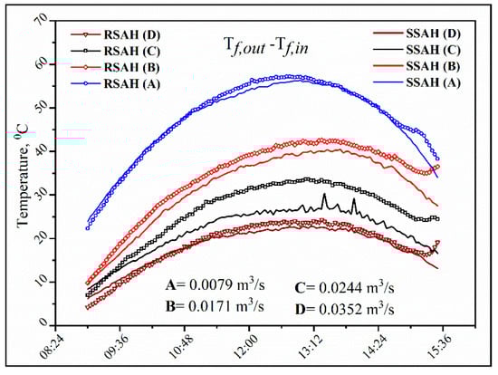
Figure 4.
Air outlet and inlet temperature difference (°C) versus daytime for the roughened and smooth SAHs at the experiment airflow rates.
It can be inferred that under stable solar radiation, the new coating with a broken arc roughness could raise the difference between the outlet and inlet temperatures of the air across the SAH compared to the smooth duct due to the increase in the heat transfer coefficient due to the turbulence effect of the employed roughness. Furthermore, the RHAS’s was higher than that of the SSAH by 1.3, 8, 19.8, and 3.3% for the A, B, C, and D airflow conditions, respectively.
3.2. Useful Energy (W), Thermal Efficiency (%,) and Nusselt Number Variation Under Different Working Conditions
The thermal efficiency of the RSAH and SSAH with CCu–BP was investigated under four airflow rates for several days, then one sunny day was selected to represent each airflow rate due to the unstable weather of Wuhan city.
Figure 5 and Figure 6 demonstrate the useful energy (W), which is calculated by Equation (5) and thermal efficiency (%), which is computed by Equation (11), respectively, under the same working conditions for both the RSAH and SSAH coated with CCu–BP. As seen in Figure 5, RSAH showed a remarkable rise in useful energy compared to the SSAH for all airflow conditions due to the high-temperature differences across the RSAH duct with respect to those across the SSAH duct. The useful energy averages were 405.18, 641.72, 711.25, and 761.20 (W) and 402.10, 599.46, 598.44, and 745.38 for the RSAH and SSAH, respectively, under working conditions A, B, C, and D.
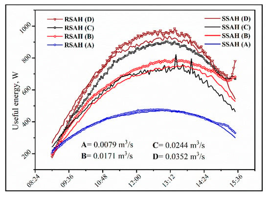
Figure 5.
Useful energy (W) variation at different airflow rates versus time for the roughened and smooth SAHs coated with CCu–BP.
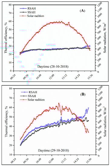
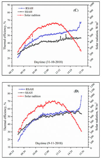
Figure 6.
Instantaneous thermal efficiency (%) of roughened and smooth SAHs coated with CCu–BP at different airflow rates (A, B, C, and D) against time.
Consequently, the instantaneous thermal efficiency of RSAH and SSAH had the same tendency of useful energy gained by the used fluid. RSAH clearly showed a higher instantaneous thermal efficiency (%) compared to the SSAHs as seen in Figure 6. The instantaneous thermal efficiency for each airflow condition ranged as follows:
- Condition A ranged from 20.5 to 30.3 with an average of 26.3 (%), and from 21.9 to 28.5 with an average of 26.1 (%) for RSAH and SSAH, respectively.
- Condition B ranged from 20.4 to 59.5 with an average of 42.1 (%), and from 19.8 to 49.3 with an average of 39.2 (%) for RSAH and SSAH, respectively.
- Condition C ranged from 21.1 to 67.3 with an average of 48.2 (%), and from 25.3 to 51.2 with an average of 40.7 (%) for RSAH and SSAH, respectively.
- Condition D ranged from 18.1 to 76.9 with an average of 49.3 (%), and from 26.6 to 57.2 with an average of 48.4 (%) for RSAH and SSAH, respectively.
It was noticeable that either the useful energy or thermal efficiency was lower for the RSAH than for the SSAH at the beginning of the experiments, and this decline was increased by the decrease in the ambient temperature as in condition D, which is because the cooled material of the Al ribs has a high heat capacity (921 J/Kg.k), so needs more energy to heat up compared to absorber without Al ribs then some of the absorbed solar radiation is lost for that purpose, which decreases the useful energy and consequently the thermal efficiency. The inverse effect occurred at the end of the experiment since the stored energy in the material of the ribs recovered to the working air and led to a higher useful energy and then a higher thermal efficiency. For more illustration, Figure 7 shows the variation in the temperature parameters ∆T/GT with thermal efficiencies of SSAH and RSAH at the mass flow rates of A, B, C, and D. Furthermore, the empirical relations and regression coefficients between them are tubulated in Table 3.
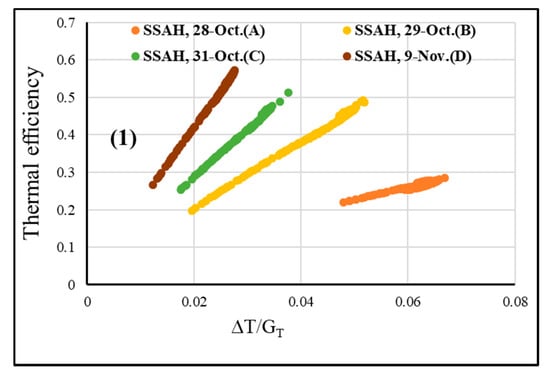
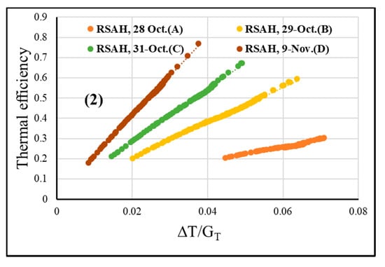
Figure 7.
Variation of thermal efficiency with ∆T/GT at different mass flow rates for (1) SSAH and (2) RSAH.
Table 3.
The empirical relations and regression coefficients for the variation of the temperature parameters ∆T/GT with the thermal efficiencies of SSAH and RSAH under working conditions.
It can be concluded that the new coating with broken arc roughness enhanced the heat transfer coefficient between the absorber plate and working fluid (air), leading to a noteworthy improvement in useful energy (W). In addition, for both useful energy and thermal efficiency, there was a positive correlation with the increase in airflow rates. Besides, the thermal efficiency of RSAH under working conditions A, B, C, and D increased by 0.8, 7.4, 18.4, and 1.9%, respectively.
The comparison of the averaged thermal efficiencies of RSAH under airflow condition C for several days is tabulated in Table 4. As illustrated in Equations (5)–(11), thermal efficiency is a function of many parameters such as solar radiation, working fluid temperature differences, heat removal factor, and overall losses coefficient. Consequently, thermal efficiency is massively affected by any variation of those variables. As seen in Table 4, despite operating the RSAH under the same airflow, the averaged thermal efficiency varied because of the different amount of incident averaged solar radiation for each day and this clearly appeared on the 24 November, which showed the lowest averaged solar radiation and the lowest thermal efficiency. To calculate the lost energy, estimating the overall heat transfer coefficient(W/m2.°C) is necessary and many parameters could affect the overall heat transfer coefficient (W/m2.°C) since there is a direct relationship between Ulos. and (Tp –Ta). The more (Tp – Ta) occurred, the more lost energy there was. The same manner was used for wind velocity, consequently the wind–heat transfer coefficient. (W/m2.°C) as mentioned in [35,36]. Despite 11 October being the day with the highest incident solar radiation, the thermal efficiency was lower than on 31 October since on 11 October, the (Tp – Ta) was the highest; also, the wind heat transfer coefficient that dramatically increased the amount of lost energy by radiation and convection consequently decreased the thermal efficiency.
Table 4.
The averages of some environmental parameters and their effect on the RSAH averaged thermal efficiency at airflow condition C on different days.
The influence of operating and the new coating with roughness parameters on the Nusselt number and heat transfer coefficient for broken arc rib roughened duct and smooth duct are discussed in the following part.
The variation of the heat transfer coefficient (W/m2.°C) and Nusselt number with the four working conditions are plotted in Figure 8 for the roughened and smooth SAHs. As predicted with the increase in the air flow rate (Reynolds number), heat transfer coefficient (W/m2.°C), and Nusselt number increases for the RSAH since an improvement in turbulent strength takes place. This might be due to the role of artificial roughness, in addition to the more volumetric airflow rates, and the greater rise in the turbulent dissipation rate aside from the turbulent kinetic energy in the flow that brings an important development in wall heat transfer rates.
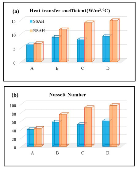
Figure 8.
Comparison between the roughened and smooth SAHs with (a) the heat transfer coefficient (W/m2. °C) and (b) the Nusselt number (dimensionless) at different volumetric air flowrates.
To conclude, the RSAH with CCu–BP showed a higher heat transfer coefficient (W/m2 °C), consequently, the Nusselt number was compared to the SSAH with CCu–BP for each working volumetric airflow rate.
3.3. Exergy Efficiency (%) and Improvement Potentials (W) for RSAH and SSAH with the New Coating
For both the RSAH and SSAH coated with CCu–BP, the second law efficiency (exergy efficiency) under different volumetric airflow rates was computed. The results are plotted in Figure 9, and the averages are tabulated in Table 5. Furthermore, the averages of exergy input (W), exergy destruction (W), and improvement potentials (W) in Equations (14)–(20) were used. It is obvious, as plotted in Figure 9, that the exergy efficiency followed the change of instantaneous output or absorbed exergy (W) within the first hour of the experiment for all working conditions; the exergy efficiency and absorbed exergy showed approximate values, and reached its peak during the period of 12:30–13:30 with a big variation between RSAH and SSAH for the benefit of RSAH because at this time, the solar radiation was in peak and RSAH could maintain a higher difference between the air outlet and inlet than the SSAH. The RSAH with CCu–BP increased the exergy efficiency by 5.9, 20, 51.6, and 29.8% for conditions A, B, C, and D, respectively, compared to SSAH with the same coating.
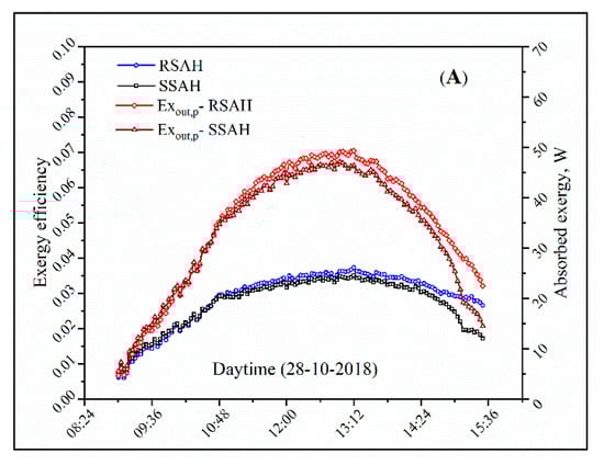
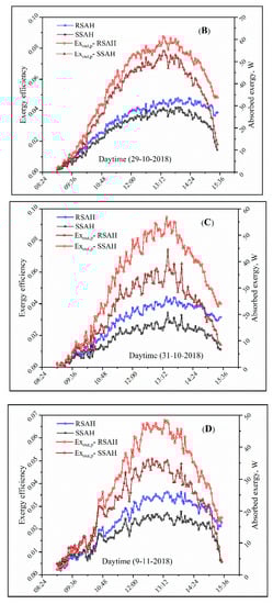
Figure 9.
Absorbed exergy (W) and exergy efficiency (fractional) comparison of the roughened and smooth SAHs coated with CCu–BP at different airflow rates (A, B, C, and D) versus time.
Table 5.
Exergy input (W), exergy destruction (W), exergy efficiency (%), and improvement potentials (W) for the roughened and smooth SAHs under the experimental working conditions.
The irreversibility of both RSAH and SSAH and their “improvement potentials” were estimated and the results revealed in Table 5, where there is a reciprocal relationship between exergy destruction and exergy efficiency as well as a temperature difference since the exergy loss is minimal when the thermal efficiency is optimum. The RSAH showed lower energy destruction and improvement potentials compared to SSAH. Furthermore, for the RSAH, the airflow rate in case D was the highest in energy destruction and improvement potentials compared to cases A, B, and C because of the high-pressure drop across the duct. In contrast, the RSAH in case C showed the lowest values of the exergy destruction and improvement potentials.
In brief, the RSAH with CCu–BP exhibited the highest increment of exergy efficiency (51.6%) under an airflow rate of 0.0244 m3/s (condition C) compared to the SSAH with the same coating. Since, in the case of condition C (Re = 2850), which lay in the transition region, from the laminar to turbulent flow showed a decline in exergy performance in this region (this behavior was noted in [11,30]). In the current study, the decline was much more for the SSAH, but for RSAH, the declination was lower because of the increase in turbulent intensity with the steady effect of the lost energy due to the increased flow rate of air. Therefore, in airflow condition C, the ratio between the RSAH and SSAH was higher and had the lowest values of exergy destruction and improvement potentials.
4. Conclusions
Artificial roughness in the form of repeated ribs is an effective way to improve the quality of SAHs. Ribs split the viscous sub-layer and created local wall turbulence due to fluid separation and reattachment without disrupting the central turbulent stream, resulting in an increase in the convective heat transfer coefficient between the air and heated surface. Therefore, in this study, a novel solar selective coating consisting of 4% CNTs/CuO-black paint was used to coat a SAH roughened with aluminum broken arc ribs. Under four airflow rates, the RSAH was evaluated in light of the First and Second Laws of Thermodynamics and compared to the SSAH coated with the same coating. The results can be concluded as follows:
(1) The maximum value of incident solar radiation was 922 W/m2 on 29 October, and the averaged ambient temperature ranged from 20.8 °C to 30.3 °C during the experiment days.
(2) The difference between the outlet and inlet of RHAS increased by 1.3, 8, 19.8, and 3.3 % for A, B, C, and D airflow conditions, respectively, over that of the SSAH.
(3) RSAH with CCu–BP showed a higher heat transfer coefficient (W/m2.°C) and Nusselt number compared to the SSAH for each working volumetric airflow rate.
(4) Employing broken arc ribs on the surface of the SAH’s absorber coated with 4% CNTs/CuO-black paint increased the thermal efficiency by 0.8, 7.4, 18.4, and 1.9 % for cases A, B, C, and D, respectively, compared to the SSAH.
(5) The thermal efficiency averages of the RSAH with CCu–BP under an air flow rate of 0.0244 m3/s (condition C) were 46.49, 48.2, and 42.82% with averages of incident solar radiation of 821.7, 729.2, and 621.4 W/m2 on 11 October, 31 October, and 24 November, respectively.
(6) The RSAH with CCu–BP exhibited the highest increment of exergy efficiency (51.6%) under an airflow rate of 0.0244 m3/s (condition C) compared to the SSAH with the same coating and had in addition, the lowest values of exergy destruction and improvement potentials.
(7) Overall, the RSAH with CCu–BP under the airflow rate of 0.0244 m3/s (condition C) exhibited the best energetic and exergetic performance.
Author Contributions
Conceptualization, T.K.A.; methodology, T.K.A, E.S.G. and S.W.; writing—original draft preparation, T.K.A.; writing—review and editing, Q.F.; supervision, Y.Z.; funding acquisition, Q.F. All authors have read and agreed to the published version of the manuscript.
Funding
This research was funded by the Ministry of Agriculture and Rural Affairs of the P.R. China as part of the project entitled the Special Fund for Agro-Scientific Research in the Public Interest (No. 201503135-11), and the Chinese Scholarships Council Foundation (No. 2016818T67).
Conflicts of Interest
The authors declare no conflict of interest.
Nomenclature
| Collector area (m2) | Useful energy (W) | ||
| Constant pressure-specific heat of the air (J/Kg. °C) | Uncertainty | ||
| Constant volume-specific heat of the air (J/Kg. °C) | Relative uncertainty for thermal efficiency | ||
| Global solar radiation (W/m2) | The effective product transmittance–absorptance. | ||
| Ambient temperature (°C) | Collector tilt (deg.) | ||
| Inlet temperature (°C) | Density (kg/m3) | ||
| Outlet temperature (°C) | Absorbed exergy of air (W) | ||
| Mean fluid temperature (°C) | Absorbed exergy of air ignoring pressure drop (W) | ||
| Mean plate temperature (°C) | Destroyed exergy (W) | ||
| Mass flowrate (kg/s) | The exergy of solar radiation (W) | ||
| The collector heat removal factor (dimensionless) | Exergy Efficiency (dimensionless) | ||
| Dh | Hydraulic diameter (m) | R | Ideal gas constant |
| Ka | Thermal conductivity of air (W/m.°C) | ||
| h | Heat transfer coefficient (W/m2.°C) | RSAH | Roughened solar air heater |
| Overall losses heat transfer coefficient (W/m2.°C) | SSAH | Smooth solar air heater | |
| Glass cover thermal emittance (%) | CNTs | Carbon nanotubes | |
| Absorber thermal emittance (%) | CuO | Cupric oxide | |
| Solar radiation power at AM1.5 | CCu-BP | 4% CNTs/CuO-black paint | |
| Spectral reflectance | N | Number of glass covers | |
| ∆T | Spectral black body emissive power at room temperature. | ||
| ASHRAE | The American Society of Heating, Refrigerating and Air-Conditioning Engineers |
References
- Hu, J.; Zhang, G. Performance improvement of solar air collector based on airflow reorganization: A review. Appl. Therm. Eng. 2019, 155, 592–611. [Google Scholar] [CrossRef]
- Kabeel, A.E.; Hamed, M.H.; Omara, Z.M.; Kandeal, A.W. Solar air heaters: Design configurations, improvement methods and applications—A detailed review. Renew. Sustain. Energy Rev. 2017, 70, 1189–1206. [Google Scholar] [CrossRef]
- El-Sebaii, A.A.; Al-Snani, H. Effect of selective coating on thermal performance of flat plate solar air heaters. Energy 2010, 35, 1820–1828. [Google Scholar] [CrossRef]
- Hernández, A.L.; Quiñonez, J.E. Experimental validation of an analytical model for performance estimation of natural convection solar air heating collectors. Renew. Energy 2018, 117, 202–216. [Google Scholar] [CrossRef]
- Fudholi, A.; Sopian, K.; Othman, M.Y.; Ruslan, M.H.; Bakhtyar, B. Energy analysis and improvement potential of finned double-pass solar collector. Energy Convers. Manag. 2013, 75, 234–240. [Google Scholar] [CrossRef]
- Ghiami, A.; Ghiami, S. Comparative study based on energy and exergy analyses of a baffled solar air heater with latent storage collector. Appl. Therm. Eng. 2018, 133, 797–808. [Google Scholar] [CrossRef]
- Yianoulis, P.; Giannouli, M.; Kalogirou, S.A. Solar Selective Coatings; Elsevier Ltd.: Amsterdam, The Netherlands, 2012; Volume 3, ISBN 9780080878737. [Google Scholar]
- Oztop, H.F.; Bayrak, F.; Hepbasli, A. Energetic and exergetic aspects of solar air heating (solar collector) systems. Renew. Sustain. Energy Rev. 2013, 21, 59–83. [Google Scholar] [CrossRef]
- Chauhan, R.; Thakur, N.S. Investigation of the thermohydraulic performance of impinging jet solar air heater. Energy 2014, 68, 255–261. [Google Scholar] [CrossRef]
- Pandey, K.M.; Chaurasiya, R. A review on analysis and development of solar flat plate collector. Renew. Sustain. Energy Rev. 2017, 67, 641–650. [Google Scholar] [CrossRef]
- Abdelkader, T.K.; Zhang, Y.; Gaballah, E.S.; Wang, S.; Wan, Q.; Fan, Q. Energy and exergy analysis of a flat-plate solar air heater coated with carbon nanotubes and cupric oxide nanoparticles embedded in black paint. J. Clean. Prod. 2019, 250, 119501. [Google Scholar] [CrossRef]
- AlShamaileh, E. Testing of a new solar coating for solar water heating applications. Sol. Energy 2010, 84, 1637–1643. [Google Scholar] [CrossRef]
- Singh Bisht, V.; Kumar Patil, A.; Gupta, A. Review and performance evaluation of roughened solar air heaters. Renew. Sustain. Energy Rev. 2018, 81, 954–977. [Google Scholar] [CrossRef]
- Singh, I.; Singh, S. A review of artificial roughness geometries employed in solar air heaters. Renew. Sustain. Energy Rev. 2018, 92, 405–425. [Google Scholar] [CrossRef]
- Hans, V.S.; Gill, R.S.; Singh, S. Heat transfer and friction factor correlations for a solar air heater duct roughened artificially with broken arc ribs. Exp. Therm. Fluid Sci. 2017, 80, 77–89. [Google Scholar] [CrossRef]
- Kumar, A.; Saini, R.P.; Saini, J.S. Heat transfer and friction factor of solar air heater having duct roughened artificially with discrete multiple v-ribs. J. Renew. Sustain. Energy 2012, 4. [Google Scholar] [CrossRef]
- Alam, T.; Saini, R.P.; Saini, J.S. Experimental Investigation of Thermohydraulic Performance of a Rectangular Solar Air Heater Duct Equipped with V-Shaped Perforated Blocks. Adv. Mech. Eng. 2014, 6, 948313. [Google Scholar] [CrossRef]
- Ravi, R.K.; Saini, R.P. Experimental investigation on performance of a double pass artificial roughened solar air heater duct having roughness elements of the combination of discrete multi V shaped and staggered ribs. Energy 2016, 116, 507–516. [Google Scholar] [CrossRef]
- Deo, N.S.; Chander, S.; Saini, J.S. Performance analysis of solar air heater duct roughened with multigap V-down ribs combined with staggered ribs. Renew. Energy 2016, 91, 484–500. [Google Scholar] [CrossRef]
- Kumar, A.; Kumar, R.; Maithani, R.; Chauhan, R.; Sethi, M.; Kumari, A.; Kumar, S.; Kumar, S. Correlation development for Nusselt number and friction factor of a multiple type V-pattern dimpled obstacles solar air passage. Renew. Energy 2017, 109, 461–479. [Google Scholar] [CrossRef]
- Kramer, K.S.; Thoma, C.; Mehnert, S.; Fahr, S. Testing solar air-heating collectors. Energy Procedia 2014, 48, 137–144. [Google Scholar] [CrossRef][Green Version]
- Bayrak, F.; Oztop, H.F.; Hepbasli, A. Energy and exergy analyses of porous baffles inserted solar air heaters for building applications. Energy Build. 2013, 57, 338–345. [Google Scholar] [CrossRef]
- Liu, H.D.; Wan, Q.; Lin, B.Z.; Wang, L.L.; Yang, X.F.; Wang, R.Y.; Gong, D.Q.; Wang, Y.B.; Ren, F.; Chen, Y.M.; et al. The spectral properties and thermal stability of CrAlO-based solar selective absorbing nanocomposite coating. Sol. Energy Mater. Sol. Cells 2014, 122, 226–232. [Google Scholar] [CrossRef]
- Carlsson, B.; Köhl, M. Recommended qualification test procedure for solar absorber surface durability. IEA SHC Task 2004, 27, 1–28. [Google Scholar]
- Duffie, J.A.; Beckman, W.A. Solar Engineering of Thermal Processes, 4th ed.; John Wiley & Sons, Inc.: Hoboken, NJ, USA, 2013; ISBN 9780470873663. [Google Scholar]
- Klein, S.A. Calculation of the monthly-average transmittance-absorptance product. Sol. Energy 1979, 23, 547–551. [Google Scholar] [CrossRef]
- Kumar, R.; Goel, V.; Singh, P.; Saxena, A.; Kashyap, A.S.; Rai, A. Performance evaluation and optimization of solar assisted air heater with discrete multiple arc shaped ribs. J. Energy Storage 2019, 26, 100978. [Google Scholar] [CrossRef]
- Rabha, D.K.; Muthukumar, P. Performance studies on a forced convection solar dryer integrated with a paraffin wax–based latent heat storage system. Sol. Energy 2017, 149, 214–226. [Google Scholar] [CrossRef]
- Akpinar, E.K.; Koçyiĝit, F. Energy and exergy analysis of a new flat-plate solar air heater having different obstacles on absorber plates. Appl. Energy 2010, 87, 3438–3450. [Google Scholar] [CrossRef]
- Bahrehmand, D.; Ameri, M.; Gholampour, M. Energy and exergy analysis of different solar air collector systems with forced convection. Renew. Energy 2015, 83, 1119–1130. [Google Scholar] [CrossRef]
- Alta, D.; Bilgili, E.; Ertekin, C.; Yaldiz, O. Experimental investigation of three different solar air heaters: Energy and exergy analyses. Appl. Energy 2010, 87, 2953–2973. [Google Scholar] [CrossRef]
- Van Gool, W. Energy policy: Fairy tales and factualities. In Innovation and Technology—Strategies and Policies; Springer: Berlin, Germany, 1997; pp. 93–105. [Google Scholar]
- Holman, J.P.; Gajda, W.J. Experimental Methods for Engineers, 8th ed.; McGraw-Hill: New York, NY, USA, 2012. [Google Scholar]
- El Khadraoui, A.; Bouadila, S.; Kooli, S.; Guizani, A.; Farhat, A. Solar air heater with phase change material: An energy analysis and a comparative study. Appl. Therm. Eng. 2016, 107, 1057–1064. [Google Scholar] [CrossRef]
- Salman, A.Z.; Hamdi, R.T.A. Theoretical Technique for Studying the Effecting Factors for Loss Coefficients Theoretical Technique for Studying the Effecting Factors for Loss Coefficients in Solar Collectors. Int. J. Trend Res. Dev. 2018, 5, 1–6. [Google Scholar]
- Maheshwari, B.K.; Karwa, R.; Gharai, S.K. Performance Study of Solar Air Heater Having Absorber Plate with Half-Perforated Baffles. ISRN Renew. Energy 2011, 2011, 1–13. [Google Scholar] [CrossRef]


© 2020 by the authors. Licensee MDPI, Basel, Switzerland. This article is an open access article distributed under the terms and conditions of the Creative Commons Attribution (CC BY) license (http://creativecommons.org/licenses/by/4.0/).