Comparison of Saturated and Superheated Steam Plants for Waste-Heat Recovery of Dual-Fuel Marine Engines


Abstract
1. Introduction
2. WHR Steam Plants Overview
3. Case Study
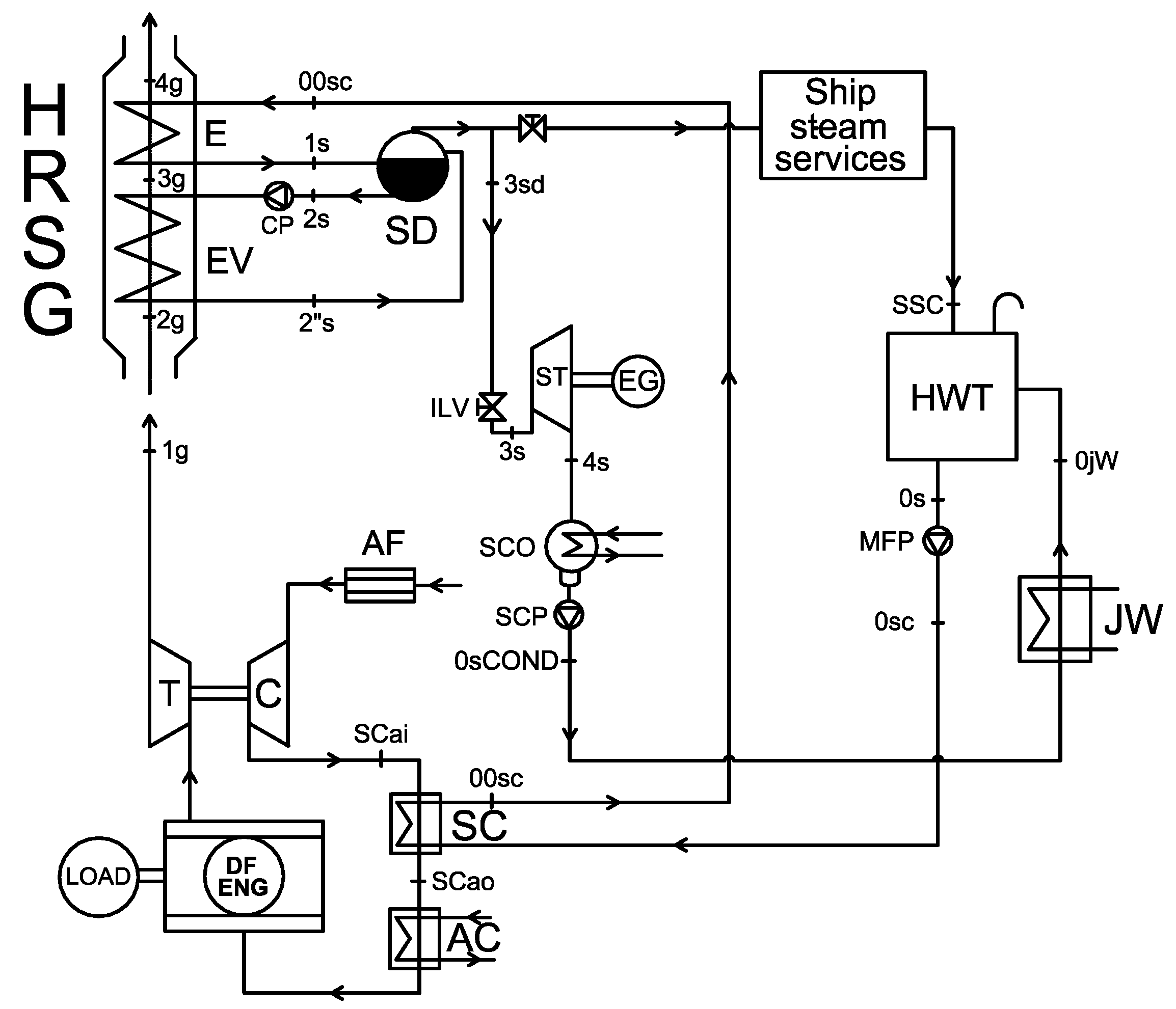
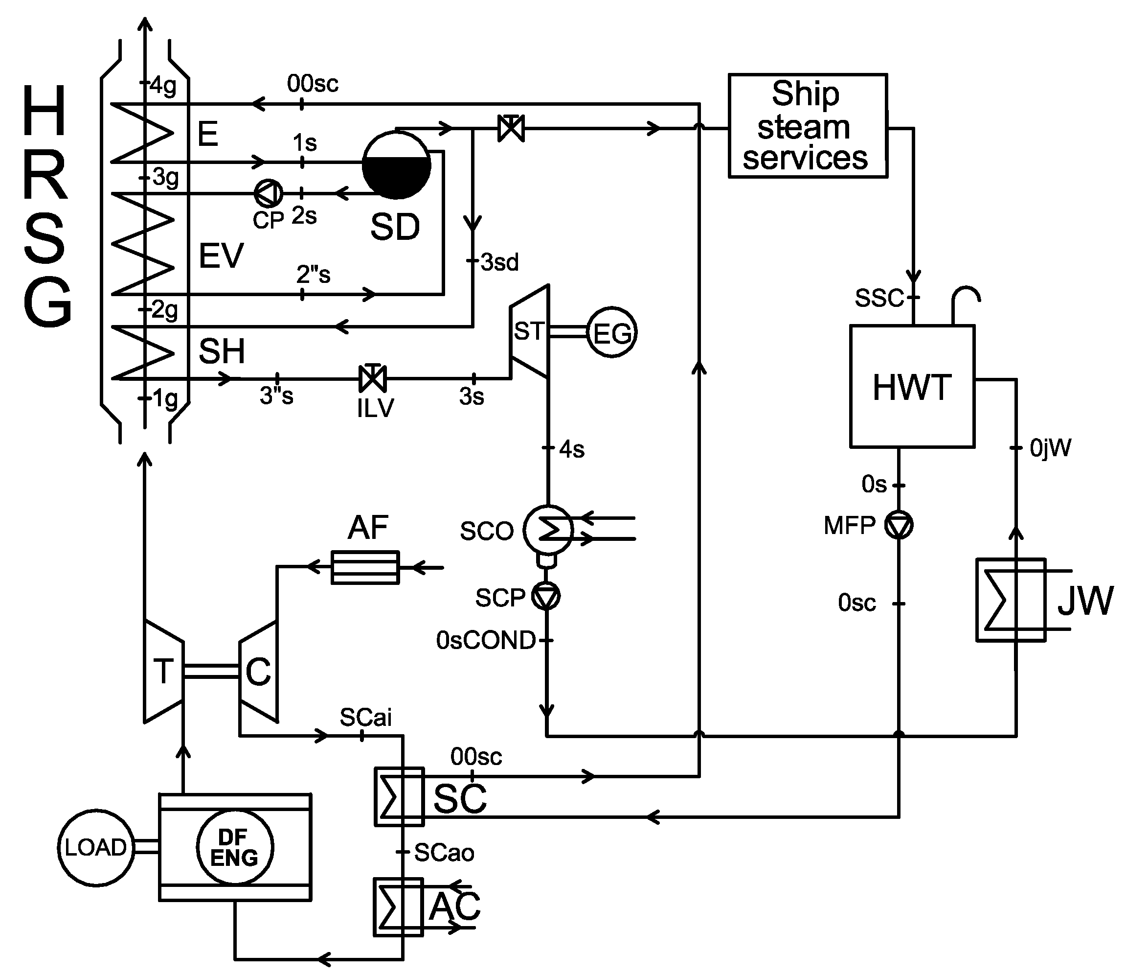
4. Schemes of the Selected WHR Steam Plants
5. WHR Steam-Plant Simulation Models
6. WHR Steam-Plant Optimization
7. WHR Steam-Plants Comparison
7.1. WHR Steam Plants Performance in Design Working Conditions
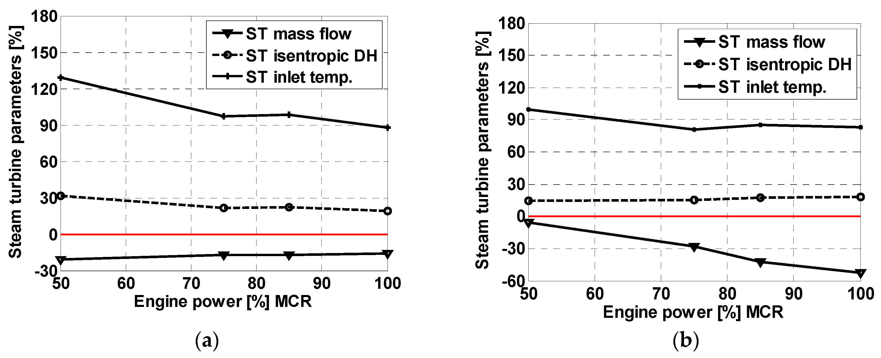
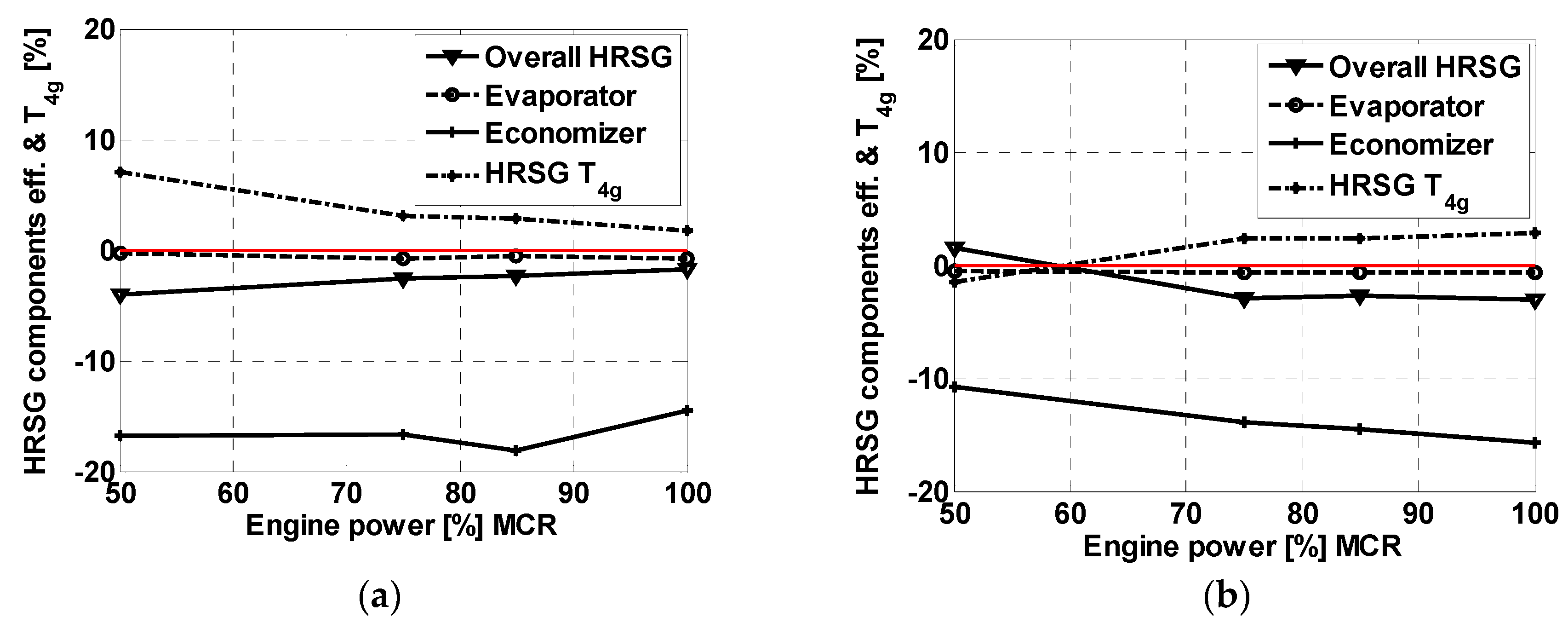
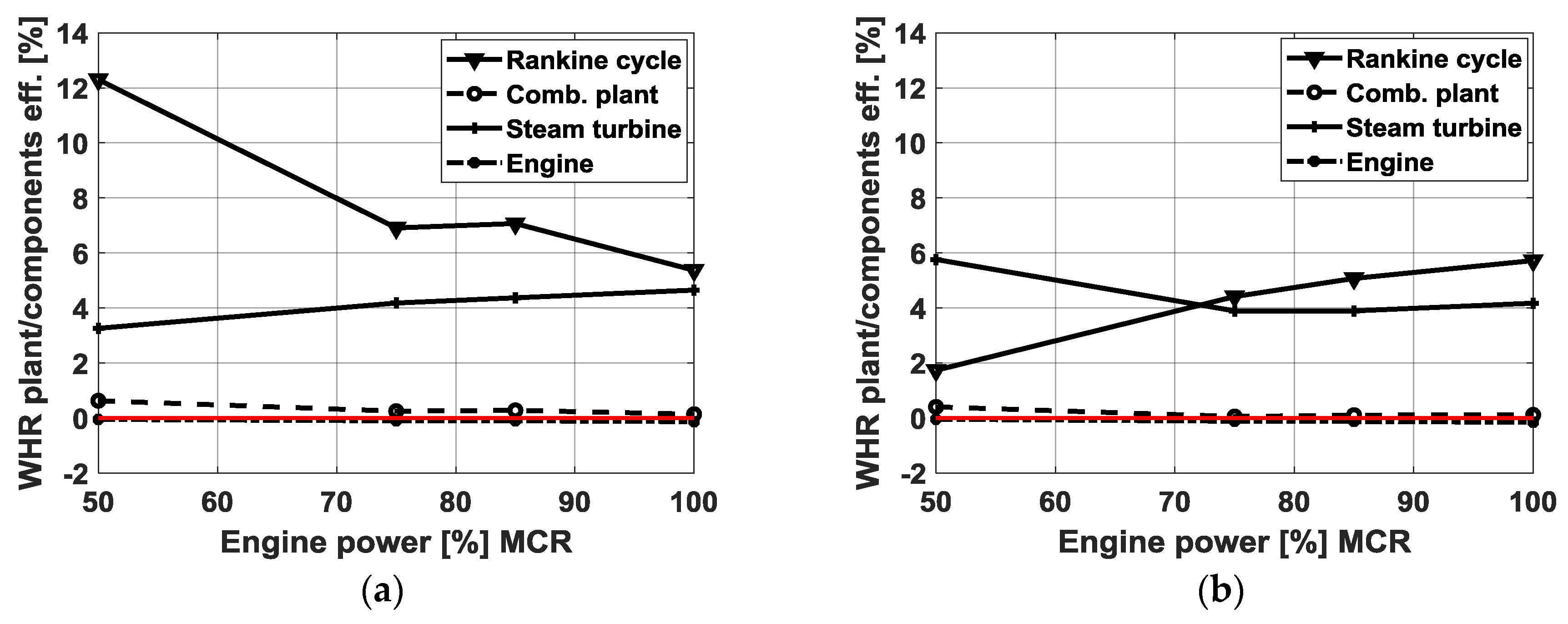
7.2. WHR Steam-Plants Performance in Off-Design Working Conditions
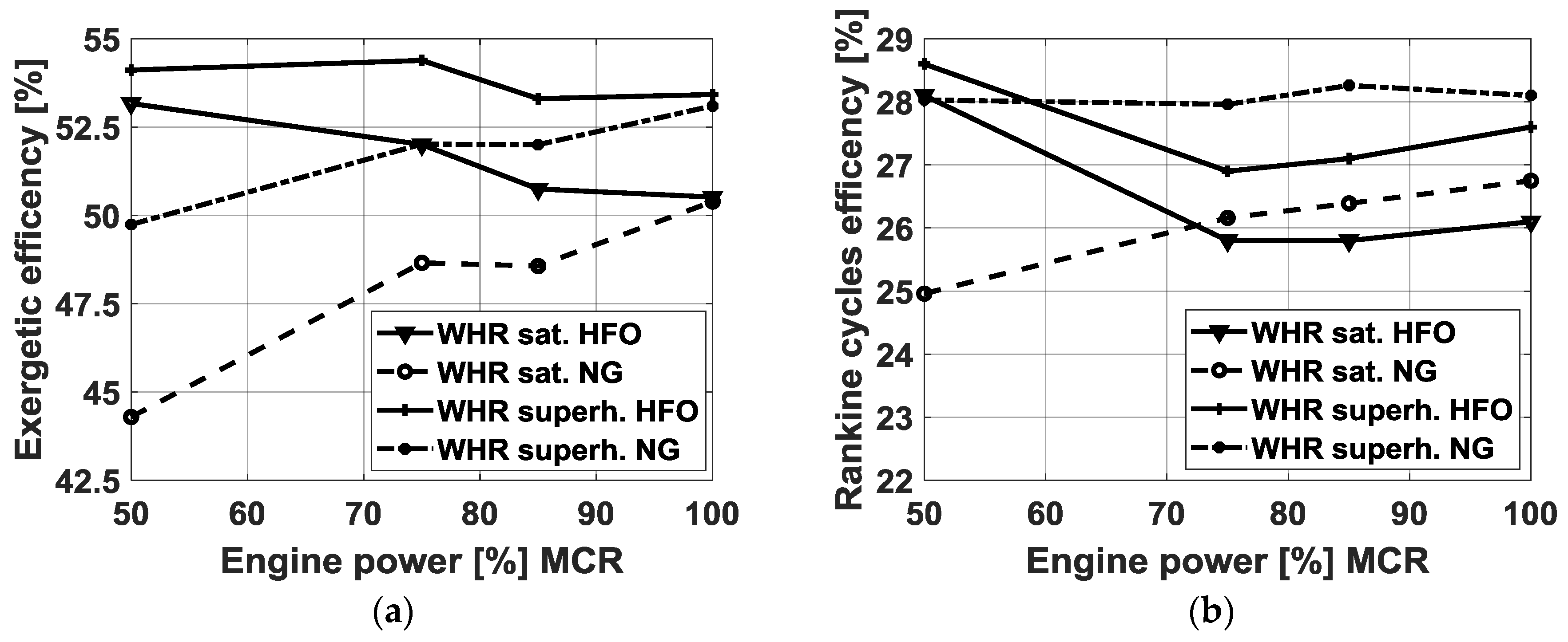
8. Exergetic Analysis
9. Conclusions
Author Contributions
Funding
Acknowledgments
Conflicts of Interest
Abbreviations List
| AC | Aftercooler |
| B.m.e.p. | Brake mean effective pressure |
| C | Turbocharger compressor |
| DF | Dual fuel |
| Diff | Difference |
| E | Economizer |
| EG | Electric generator |
| EV | Evaporator |
| HFO | Heavy fuel oil |
| HRSG | Heat recovery steam generator |
| HWT | Heat water tank |
| ILV | Isenthalpic lamination valve |
| JW | Jacket water |
| MCR | Maximum continuous rating |
| MDO | Marine diesel oil |
| MFP | Main feed pump |
| NCR | Normal continuous rating |
| NG | Natural gas |
| Sat | Saturated steam |
| SC | Scavenging system |
| SCO | steam condenser |
| SCP | Steam condenser pump |
| SD | Steam drum |
| ST | Steam turbine |
| Superh | Superheated steam |
| T | Turbocharger turbine, temperature |
| WHR | Waste heat recovery |
References
- Le Fevre, C.N. A Review of Demand Prospects for LNG as a Marine Fuel; Oxford Institute for Energy Studies: Oxford, UK, 2018; ISBN 978-1-78467-114-3. [Google Scholar]
- International Maritime Organization (IMO). Report of the Marine Environment Protection Committee (MEPC) on its Fifty-Seventh Session; IMO: London, UK, 2008. [Google Scholar]
- Marine Environment Protection Committee (MEPC). Resolution, MECP 212 (63/23), Annex 8. Adopted on 2 March 2012. Guidelines to the Method of Calculation of the Attained Energy Efficiency Design Index (EEDI) for New Ships. Available online: http://www.imo.org/en/KnowledgeCentre/IndexofIMOResolutions/Marine-Environment-Protection-Committee-%28MEPC%29/Documents/MEPC.212%2863%29.pdf (accessed on 22 December 2019).
- Marine Environment Protection Committee (MECP). In Proceedings of the International Maritime Organization (IMO), 66th Session, London, UK, 31 March–4 April 2014.
- Altosole, M.; Benvenuto, G.; Campora, U.; Laviola, M.; Zaccone, R. Simulation and Performance Comparison between Diesel and Natural Gas Engines for Marine Applications. Proc. Inst. Mech. Eng. Part M J. Eng. Marit. Environ. 2017, 231, 690–704. [Google Scholar] [CrossRef]
- Livanos, G.A.; Theotokatos, G.; Pagonis, D.N. Techno-economic investigation of alternative propulsion plants for Ferries and RoRo ships. Energy Convers. Manag. 2014, 79, 640–651. [Google Scholar] [CrossRef]
- Serrano, J.R.; Olmeda, P.; Tiseira, A.; García-Cuevas, L.M.; Lefebvre, A. Theoretical and experimental study of mechanical losses in automotive turbochargers. Energy 2013, 55, 888–898. [Google Scholar] [CrossRef]
- Altosole, M.; Benvenuto, G.; Campora, U.; Silvestro, F.; Terlizzi, G. Efficiency Improvement of a Natural Gas Marine Engine Using a Hybrid Turbocharger. Energies 2018, 11, 1924. [Google Scholar] [CrossRef]
- Mamat, A.M.; Romagnoli, A.; Martinez-Botas, R.F. Characterisation of a low pressure turbine for turbocompounding applications in a heavily downsized mild-hybrid gasoline engine. Energy 2014, 64, 3–16. [Google Scholar] [CrossRef]
- Poran, A.; Thawko, A.; Eyal, A.; Tartakovsky, L. Direct injection internal combustion engine with high-pressure thermochemical recuperation-Experimental study of the first prototype. Int. J. Hydrog. Energy 2018, 43, 11969–11980. [Google Scholar] [CrossRef]
- Choi, Y.; Negash, A.; Kim, T.Y. Waste heat recovery of diesel engine using porous medium-assisted thermoelectric generator equipped with customized thermoelectric modules. Energy Convers. Manag. 2019, 197. [Google Scholar] [CrossRef]
- Javani, N.; Dincer, I.; Naterer, G.F. Thermodynamic analysis of waste heat recovery for cooling systems in hybrid and electric vehicles. Energy 2012, 46, 109–116. [Google Scholar] [CrossRef]
- Altosole, M.; Benvenuto, G.; Campora, U.; Laviola, M.; Trucco, A. Waste Heat Recovery from Marine Gas Turbines and Diesel Engines. Energies 2017, 10, 718. [Google Scholar] [CrossRef]
- Tu, H.; Fan, H.; Lei, W.; Zhou, G. Options and Evaluations on Propulsion Systems of LNG Carriers; IntechOpen©: London, UK, 2019. [Google Scholar] [CrossRef]
- Fernández, I.A.; Gómez, M.R.; Gómez, J.R.; Insua, Á.B. Review of propulsion systems on LNG carriers. Renew. Sustain. Energy Rev. 2017, 67, 1395–1411. [Google Scholar] [CrossRef]
- Ioannidis, J. Thermo Efficiency System (TES) for Reduction of Fuel Consumption and CO2 Emission; Aalborg A.G.: Copenhagen, Denmark, 1984. [Google Scholar]
- Hansen, J.P. Diesel engine waste Heat Recovery-Possibilities and Limitations. In Proceedings of the ICMES 90, Maritime Systems Integrity, the University of Newcastle-upon-Tyne, Great Britain, UK, 19–21 September 1990. [Google Scholar]
- Shmid, H. Less Emissions through Waste Heat Recovery; Wartsila Switzerland Ltd.: Winterthur, Switzerland, 2004. [Google Scholar]
- Tien, W.K.; Yeh, R.H.; Hong, J.M. Theoretical Analysis of Cogeneration System for Ships. Energy Convers. Manag. 2007, 48, 1965–1974. [Google Scholar] [CrossRef]
- Dzida, M.; Muchasrki, J. On the Possible Increasing of Efficiency of Ship Power Plant with the System Combined of marine Diesel Engine, Gas Turbine and Steam Turbine, at the Main Engine-Steam Turbine Mode of Cooperation. Polish Marit. Res. 2009, 16, 47–52. [Google Scholar] [CrossRef]
- Grimmelius, H.; Boonen, E.J.; Nicolai, H.; Stapersma, D. The integration of Mean Value First Principle Diesel Engine models in Dynamic Waste Heat and Cooling Load Analysis. In Proceedings of the CIMAC Congress, Bergen, Norway, 14‒17 June 2010; p. 280. [Google Scholar]
- Dimopoulos, G.G.; Georgopoulou, C.A.; Kakalis, N.M.P. Modelling and Optimisation of an Integrated Marine Combined Cycle System. In Proceedings of the ECOS 2011, Novi Sad, Serbia, 4–11 July 2011; pp. 1283–1298. [Google Scholar]
- MAN Diesel & Turbo. Waste Heat Recovery System (WHRS) for Reduction of Fuel Consumption, Emissions and EEDI; MAN Diesel & Turbo Society: Copenhagen, Denmark, 2011. [Google Scholar]
- Benvenuto, G.; Campora, U.; Trucco, A. Optimization of Waste Heat Recovery from the Exhaust Gas of Marine Diesel Engines. Proc. Inst. Mech. Eng. Part M J. Eng. Marit. Environ. 2014, 230, 83–94. [Google Scholar] [CrossRef]
- Zymaris, A.S.; Alnes, Ø.Å.; Knutsen, K.E.; Kakalis, N.M.P. Towards a model-based condition assessment of complex marine machinery systems using systems engineering. Energy Res. 2016, 10, 75–85. [Google Scholar] [CrossRef]
- Altosole, M.; Campora, U.; Laviola, M.; Zaccone, R. Waste Heat Recovery from Dual-Fuel Marine Engine. In Maritime Transportation and Harvesting of Sea Resources; Soares, C.G., Teixeira, À.P., Eds.; Taylor and Francis Group: London, UK, 2018; ISBN 978-0-8153-7993-5. [Google Scholar]
- Altosole, M.; Campora, U.; Laviola, M.; Zaccone, R. Deterioration effects on the performance of a steam plant for the waste heat recovery from a marine diesel engine. Ships Offshore Struct. 2019. [Google Scholar] [CrossRef]
- Andreasen, J.G.; Meroni, A.; Haglind, F. A Comparison of Organic and Steam Rankine Cycle Power Systems for Waste Heat Recovery on Large Ships. Energies 2017, 10, 547. [Google Scholar] [CrossRef]
- Benvenuto, G.; Campora, U.; Laviola, M.; Zaccone, R. Comparison of Waste Heat Recovery Systems for the Refitting of a Cruise Ferry. In Proceedings of the NAV 2015, 18th International Conference on Ships and Shipping Research, Lecco, Italy, 24–26 June 2015; Altosole, M., Francescutto, A., Eds.; pp. 404–415, ISBN 978-88-940557-1-9. [Google Scholar]
- MAN Diesel & Turbo. MAN 51/60DF Project Guide, Marine Four Stroke Dual Fuel Engine; MAN Diesel & Turbo: Copenhagen, Denmark, 2014. [Google Scholar]
- Cohen, H.; Rogers, G.F.C.; Saravanamuttoo, H.I.H. Gas Turbine Theory, 3rd ed.; Longman Scientific and Technical: Harlow, Essex, UK, 1987. [Google Scholar]
- Gundersen, T. An introduction to the concept of exergy and energy quality. Energy Process Eng. 2011, 4, 1–26. [Google Scholar]
- Baldi, F.; Gabrielli, C. A feasibility analysis of waste heat recovery systems for marine applications. Energy 2015, 80, 654–665. [Google Scholar] [CrossRef]


| Engine Parameters | Current Engine | New Engine |
|---|---|---|
| Wärtsilä 16V 46C | MAN 51/60 18V DF | |
| Length (mm) | 12,871 | 13,644 |
| Height (mm) | 5854 | 5517 |
| Width (mm) | 4678 | 4713 |
| Dry weight (tons) | 233 | 265 |
| Cylinders number | 16 | 18 |
| Bore (mm) | 460 | 510 |
| Stroke (mm) | 580 | 600 |
| Fuel type | HFO | HFO/NG |
| MCR power (kW) at 500 rpm | 16,800 | 17,550 |
| B.m.e.p. (bar) | 26.14 | 19.09 |
| Injection type | single | double |
| Efficiency (%) | 45.97 | 47.68 (NG) |
| Design-Code Results | % Error |
|---|---|
| HPTi: turbine inlet high pressure | 0.01 |
| LPTi: turbine inlet low pressure | 0.00 |
| MS HP: turbine inlet steam mass-flow rate | 0.05 |
| MS LP: turbine inlet steam mass-flow rate | 0.52 |
| ToutG: HRSG outlet gas temperature | 0.54 |
| PST: steam turbine power | 0.75 |
| Fixed WHR Plant Parameters | NG Fuel |
|---|---|
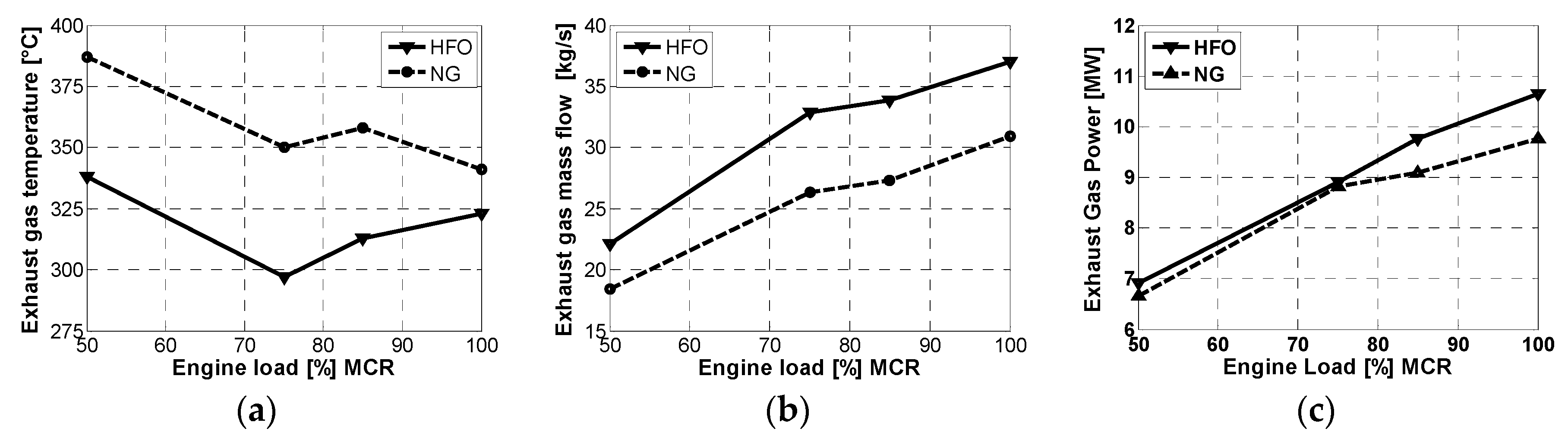
| Engine exhaust gas mass flow rate (kg/s) | 26 |
| Engine exhaust gas temperature (°C) | 352 |
| Condenser pressure (bar) | 0.08 |
| Plan dimensions of the HRSG (m × m) | 1.85 × 2.10 |
| HRSG Optimization Parameters | Variation Range | Variation Steps |
|---|---|---|
| HRSG steam drum pressure (bar) | 5–20 | 0.1 |
| Pinch point temp. differences: ΔT pp (°C) | 5–20 | 1 |
| Approach point temperature diff.: ΔT ap (°C) for superheated steam plant | 5–35 | 1 |
| Optimized HRSG Parameters | NG Fuel | ||
|---|---|---|---|
| WHR Saturated Steam | WHR Superheated Steam | WHR Difference (%) | |
| HRSG steam drum pressure (bar) | 7.6 | 8 | 5.26 |
| Pinch point temp. difference: ΔT pp (°C) | 5.1 | 5 | −1.96 |
| Approach point temp difference: ΔT ap (°C) | - | 17 | - |
| Optimized Main HRSG Data | |||
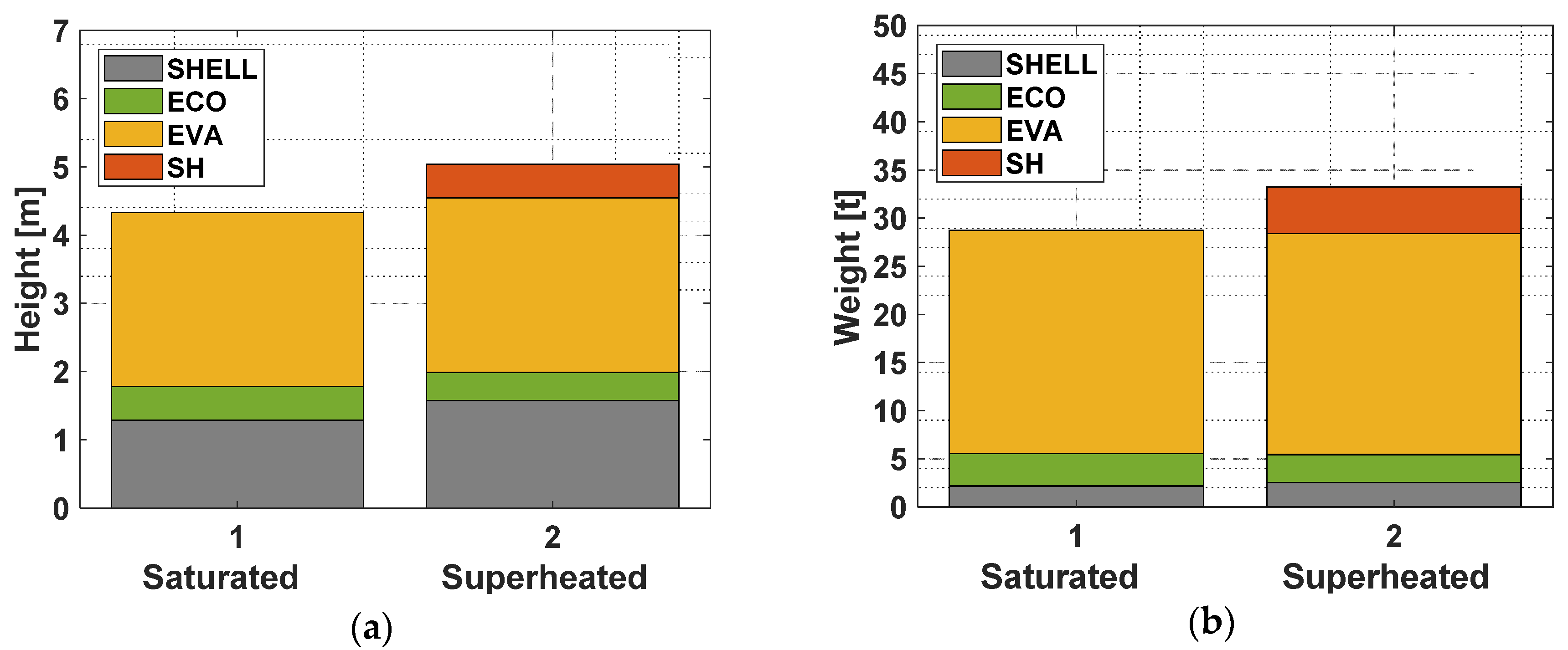
| HRSG height [m] | 4.33 | 5.04 | 16.26 |
| HRSG weight [t] | 28.75 | 33.26 | 15.67 |
| Economizer pipe number | 7 | 6 | −14.29 |
| Evaporator pipe number | 34 | 34 | 0.0 |
| Superheater pipe number | - | 7 | - |
| HRSG Parameters | HFO Fuel | ||
|---|---|---|---|
| WHR Saturated Steam | WHR Superheated Steam | WHR Difference (%) | |
| HRSG steam drum pressure (bar) | 7.1 | 7.3 | 2.81 |
| Pinch point temp. difference: ΔT pp (°C) | 7.2 | 7.9 | 9.72 |
| Approach point temp difference: ΔT ap (°C) | - | 7.3 | - |
| WHR Plants Data | |||
| ST inlet pressure (% of pSD) | 70 | 70 | 0.0 |
| HRSG gas outlet temperature (°C) | 165.3 | 169.3 | 2.38 |
| HRSG Parameters | NG Fuel | HFO Fuel | |||||
|---|---|---|---|---|---|---|---|
| WHR Sat. Steam | WHR Superh. Steam | WHR Diff. (%) Δx/x 100 | WHR Sat. Steam | WHR Superh. Steam | WHR Diff. (%) Δx/x 100 | ||
| 1 | Overall HRSGeff (%) | 58.37 | 56.85 | −2.61 | 48.40 | 46.95 | −2.99 |
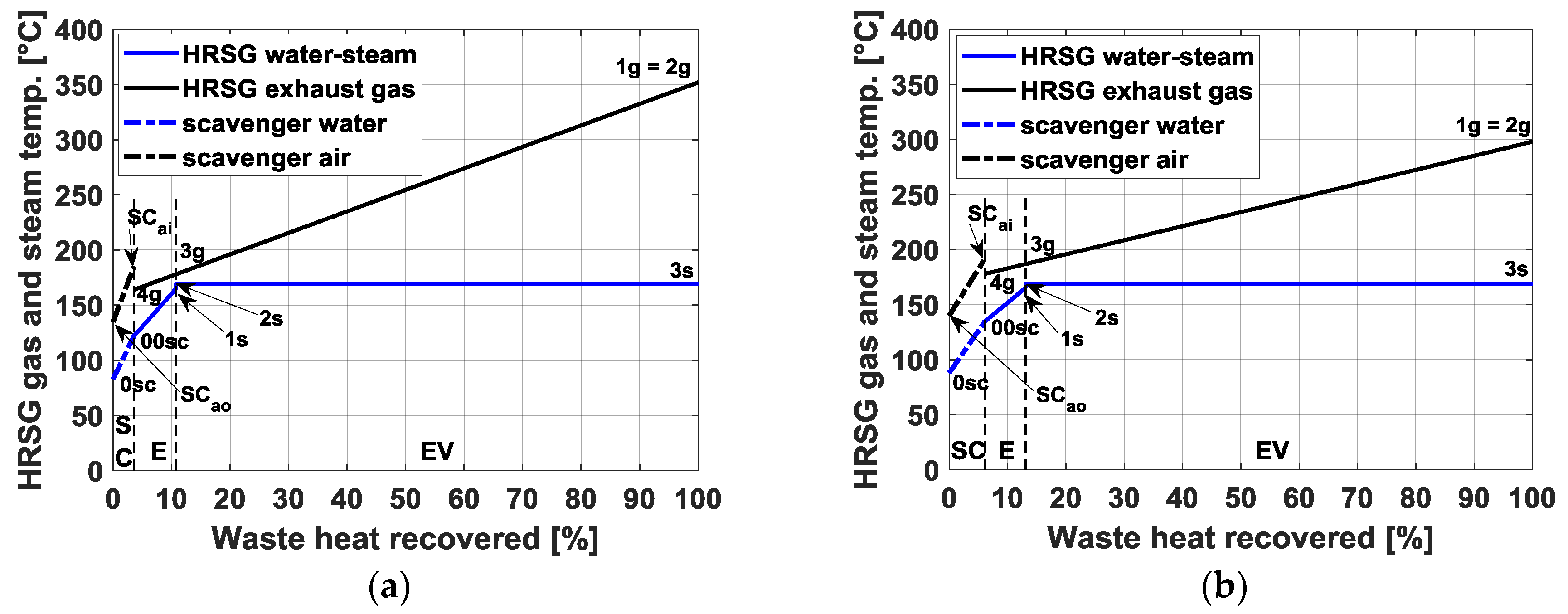
| 2 | HRSG gas outlet temperature (°C) | 160.3 | 165.2 | 3.08 | 165.3 | 169.3 | 2.38 |
| 3 | HRSG gas side pressure loss (mbar) | 30.01 | 34.94 | 16.46 | 43.03 | 50.27 | 16.52 |
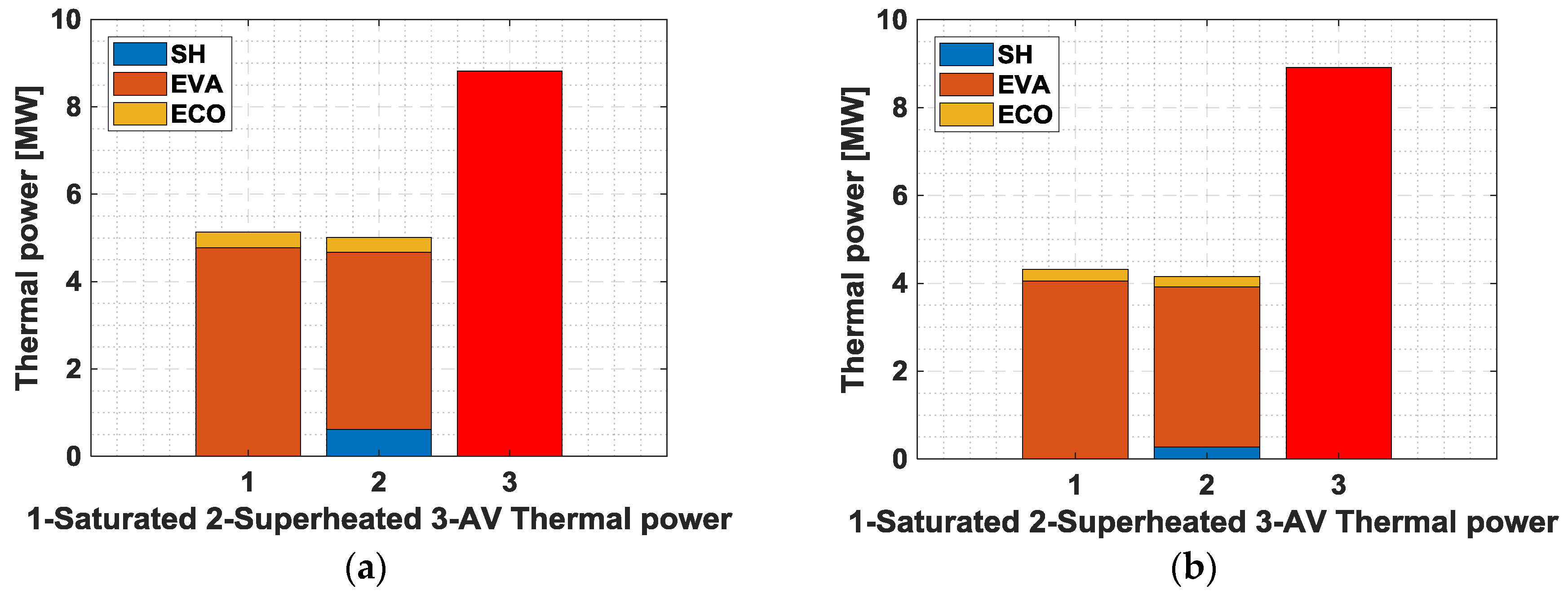
| 4 | Exchanged E thermal power (MW) | 0.36 | 0.32 | −10.66 | 0.26 | 0.24 | −7.15 |
| 5 | E water-mass flow rate (kg/s) | 2.27 | 1.91 | −15.85 | 2.44 | 2.18 | −10.65 |
| 6 | E water inlet temperature (°C) | 121.1 | 125.3 | 3.47 | 134.2 | 136.8 | 1.94 |
| 7 | E water outlet temperature (°C) | 157.8 | 161.7 | 2.47 | 165.2 | 166.1 | 0.54 |
| 8 | E gas inlet temperature (°C) | 174.1 | 177.8 | 2.16 | 173.4 | 176.8 | 2.00 |
| 9 | E efficiency (%) | 26.26 | 21.87 | −16.72 | 20.96 | 18.03 | −13.94 |
| 10 | EV exchanged thermal power (MW) | 4.77 | 4.04 | −15.35 | 4.06 | 3.64 | −10.18 |
| 11 | EV steam drum temperature (°C) | 168.3 | 170.4 | 1.24 | 165.6 | 166.7 | 0.66 |
| 12 | EV gas inlet temperature (°C) | 350 | 328 | −6.29 | 297.0 | 287.6 | −3.17 |
| 13 | EV efficiency (%) | 97.19 | 96.46 | −0.75 | 94.46 | 93.80 | −0.71 |
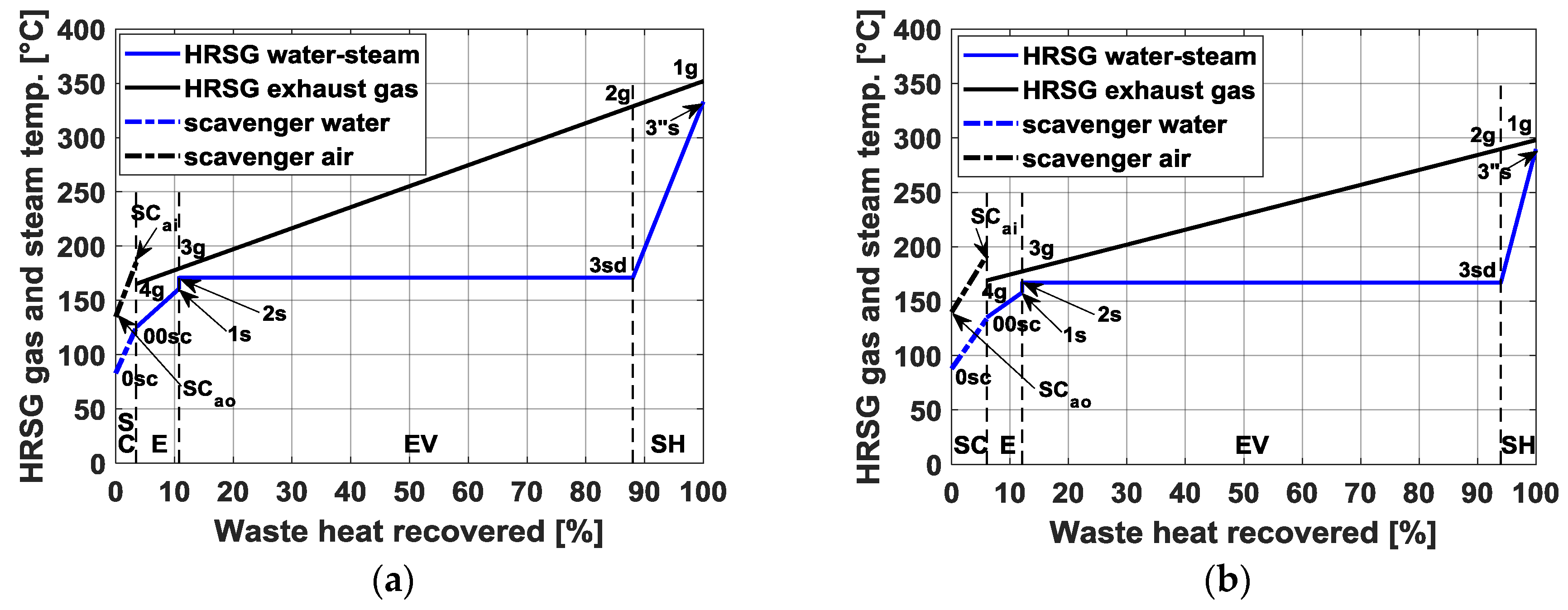
| 14 | SH exchanged thermal power (MW) | - | 0.62 | - | - | 0.27 | - |
| 15 | SH steam outlet temperature (°C) | - | 332.9 | - | - | 289.7 | - |
| 16 | SH gas inlet temperature (°C) | - | 350.0 | - | - | 297.0 | - |
| 17 | SH efficiency (%) | - | 12.43 | - | - | 6.14 | - |
| Engine, Steam-Plant Components, and Combined Plant Data | NG Fuel | HFO Fuel | |||||
|---|---|---|---|---|---|---|---|
| WHR Sat. Steam | WHR Superh. Steam | WHR Diff. (%) Δx/x 100 | WHR Sat. Steam | WHR Superh. Steam | WHR Diff. (%) Δx/x 100 | ||
| 1 | HRSG p loss. Esfc incr. (g/kWh) | 0.92 | 1.07 | 16.46 | 1.31 | 1.52 | 16.50 |
| 2 | ηE (%) | 47.28 | 47.23 | −0.10 | 45.67 | 45.61 | −0.12 |
| 3 | ηRankine (%) | 26.16 | 27.96 | 6.91 | 25.80 | 26.91 | 4.41 |
| 4 | ηCP (%) | 50.88 | 51 | 0.25 | 47.93 | 47.95 | 0.05 |
| 5 | NCR engine power (kW) | 13162.5 | 13162.5 | 0.0 | 13162.5 | 13162.5 | 0.0 |
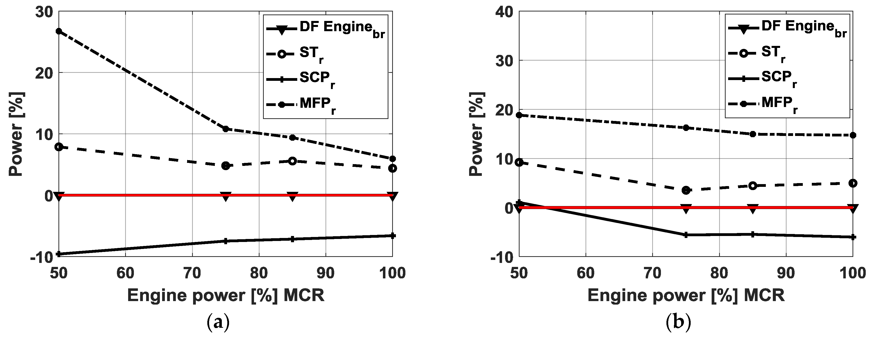
| 6 | ST power (kW) | 1014.0 | 1062.5 | 4.81 | 657.2 | 679.6 | 3.41 |
| 7 | ST inlet pressure (% of pSD) | 100 | 100 | 0.0 | 70 | 70 | 0.0 |
| 8 | ST ΔHid (kJ/kg) | 678.2 | 825.7 | 21.76 | 494.1 | 570.4 | 15.43 |
| 9 | ST mass flow rate (kg/s) | 2.10 | 1.74 | −17.38 | 1.87 | 1.61 | −13.90 |
| 10 | ST efficiency (%) | 71.0 | 74.0 | 4.18 | 71.2 | 74.0 | 3.89 |
| 11 | ST outlet steam quality | 0.87 | 0.97 | 12.00 | 0.87 | 0.95 | 9.40 |
| 12 | condenser thermal power (kW) | 4390 | 4074.6 | −7.18 | 3918.7 | 3591.1 | −5.81 |
| 13 | SCP pump power (kW) | 17.63 | 16.32 | −7.46 | 11.63 | 10.98 | −5.57 |
| 14 | MFP pump power (kW) | 4.51 | 4.99 | 10.8 | 3.58 | 4.16 | 16.24 |
| 15 | SSS mass flow rate (kg/s) | 0.17 | 0.17 | 0.0 | 0.57 | 0.57 | 0.0 |
© 2020 by the authors. Licensee MDPI, Basel, Switzerland. This article is an open access article distributed under the terms and conditions of the Creative Commons Attribution (CC BY) license (http://creativecommons.org/licenses/by/4.0/).
Share and Cite
Altosole, M.; Benvenuto, G.; Zaccone, R.; Campora, U. Comparison of Saturated and Superheated Steam Plants for Waste-Heat Recovery of Dual-Fuel Marine Engines. Energies 2020, 13, 985. https://doi.org/10.3390/en13040985
Altosole M, Benvenuto G, Zaccone R, Campora U. Comparison of Saturated and Superheated Steam Plants for Waste-Heat Recovery of Dual-Fuel Marine Engines. Energies. 2020; 13(4):985. https://doi.org/10.3390/en13040985
Chicago/Turabian StyleAltosole, Marco, Giovanni Benvenuto, Raphael Zaccone, and Ugo Campora. 2020. "Comparison of Saturated and Superheated Steam Plants for Waste-Heat Recovery of Dual-Fuel Marine Engines" Energies 13, no. 4: 985. https://doi.org/10.3390/en13040985
APA StyleAltosole, M., Benvenuto, G., Zaccone, R., & Campora, U. (2020). Comparison of Saturated and Superheated Steam Plants for Waste-Heat Recovery of Dual-Fuel Marine Engines. Energies, 13(4), 985. https://doi.org/10.3390/en13040985