1. Introduction
There are a number of changes simultaneously taking place in electricity supply systems, which include: the increasing deployment of Variable Renewable Energy Sources (VRES), such as wind and solar energy; and the desire to electrify more of the current demand, including heat (domestic, commercial and industry) and transport (mainly via the deployment of electric vehicles) [
1]. Any single one of these changes creates challenges for the electricity supply system due to the extra demand and greater difficulties in forecasting potential imbalances between demand and production [
2,
3]. However, there are also opportunities available to minimise these challenges with the adoption of Demand Side Management (DSM) to help mitigate against imbalances [
2].
With the increase in VRES, there is already a need to deploy nuclear power plants in a flexible manner. The current power manoeuvrability limitations on Light Water Reactors (LWRs) are well documented [
4] but the fundamental reason for these limitations is not adequately captured in the open-literature. The economics of operating plants will not be discussed here and the focus is on the technical potential, with the fundamental reasoning behind certain operation constraints which are not captured in the literature discussed. The emphasis in this study is on Pressurised Water Reactors (PWRs) given that they make up the majority of existing LWR systems deployed to date [
5].
In the context of flexible power operation, the main parameters for any power plant (including nuclear plants) are the following [
6]:
Ramp rates (rate of change in power and the power increment);
Minimum power output permitted for long-term operation; and
Restart times (from shutdown).
It is important to distinguish between the different manners in which nuclear power plants can achieve flexible power operation, these are [
6]:
Frequency responsive operation, where the plant is set to operate at less than full load, and its output varies in response to changes in the system frequency.
Profile operation in which the operator offers periodic load changes to create a profile which varies across the day (typically this involves “two shifting” over a 24 h period with reduced output overnight).
Load following, where the operator is instructed by the system operator to carry out manoeuvres at short notice to change the output in accordance with changing system requirements.
In the literature the term load following is sometimes used to refer to the above definitions of load following and profile operation. In this report the distinct flexible power operating modes will be differentiated using the above definitions. In addition to the above, it is important to consider other services the reactors can offer, principally inertia and frequency response, which are discussed in
Section 3.
After briefly considering options to accommodate mismatches in supply and demand that do not rely on power plants undergoing power manoeuvres, we outline the important role Nuclear Power Plants (NPPs) currently play in many markets in maintaining grid stability via services related to inertia, frequency control and power manoeuvres. Furthermore, we provide details on how NPPs undertake profile operation and load following, both in the context of UK and international experience. We also provide a detailed summary of the current power manoeuvrability characteristics of NPPs, along with a comparison to other conventional plants, focusing on: ramp rates, minimum power levels and restart times. This is followed by a discussion on the reactor physics considerations when operating plants in a flexible manner and also other mechanisms, principally fatigue, that limit flexible operation in NPPs. Finally, we consider alternative means to provide large rapid power changes in NPPs. Whilst this study focuses on current PWR plants, it also considers Small Modular Pressurised Water Reactor (SM-PWR) plants which might offer benefits with respect to improved power manoeuvrability. In this study there is a particular focus, for the first time in the open-literature, on UK experience with operating LWR plants in a flexible manner. Therefore, we have undertaken discussions with plant operators in the UK when considering the implications on increasing power manoeuvrability in NPPs.
2. Mechanisms to Accommodate Mismatches in Supply and Demand
There is interest in using DSM and battery technology to address challenges with greater electrification of demand and increasing deployment of VRES but both approaches have their limitations. Most DSM discussed in the literature is sufficient for dealing with intra-day fluctuations, for example by delaying washing, controlling the timing of electric vehicle charging to minimise demand at peak times, modifying some elements of industrial energy demand and modifying the timing when air-conditioning units are activated [
2,
7,
8,
9]. Note that there are only limited domestic and commercial demands that can be delayed for periods of longer than a day [
2]. There are additional challenges associated with varying industrial demand since: (1) many industries are operating near 100% capacity and unable to increase demand; (2) they have very small buffers making varying output very difficult; and (3) it can take several hours or days to achieve stable output after a pause in production [
10].
To deal with fluctuations in demand lasting for periods of time longer than is amenable via DSM there will be a need to reduce the power outputs of different plants (including nuclear plants) for some time or potentially increase power output at short notice. In the case of fluctuations in demand and production lasting for weeks, the only viable mechanism to deal with this is large-scale storage or having plants operating in standby (active reserve) for much of the year, which can then be called upon at short notice [
11,
12,
13]. Nevertheless, greater flexibility in power plants and DSM can provide useful mechanisms to ensure demand is met, apart from in the most challenging scenarios [
2]. The challenges are dependent on the extent of VRES supply, particularly in meeting the around 400 h of demand when supply is low and demand high (namely in winter months) [
2,
14].
There is a general trend for reactors to operate at lower capacity (part load) as more VRES is deployed [
14]. An alternative approach is to use additional facilities to transform excess energy when demand is low to another useful product, e.g., hydrogen created using an electrolysis plant. This approach would allow the reactor to operate at a higher capacity factor. However, simply aiming to capture nuclear power via an additional facility, for instance through the production of hydrogen, needs to factor in the low capacity factors of the hydrogen plant for much of the year. The low capacity factor of the additional facility will have negative economic impacts when considering the whole system cost (i.e., the cost of the nuclear plant and hydrogen plant) [
15]. Flexible power production can help over short periods of time and when there is excess demand. However, when demand is high there will be the need for large-scale storage or peak load production which is likely to be reliant on gas plants due to their low capital cost and high running costs. As the demand on gas plants increases, the impact on greenhouse gas production can be high. There is interest in the adoption of flexible gas plants with Carbon Capture and Storage (CCS) but challenges exist in making flexible CCS economically viable (for instance the extra systems, such as intermediate storage tanks, required to improve flexibility, can add to the capital cost of the plant) [
16,
17].
3. The Role of Nuclear Power in Supporting Grid Stability
3.1. Inertia, Response and Reserve
Conventional power plants (nuclear, fossil fuel and those burning biomass) exhibit inertia in the event a fault occurs at the plant [
18]. That is to say the power plants do not immediately stop producing energy but the powerful turbines these plants utilise start to spin down resulting in a noticeable reduction of grid frequency over a period of ∼10 s. The fact that the frequency reduction is not immediate means that other systems, in particular power plants which exhibit frequency response, have time to respond and are able to halt further falls in grid frequency.
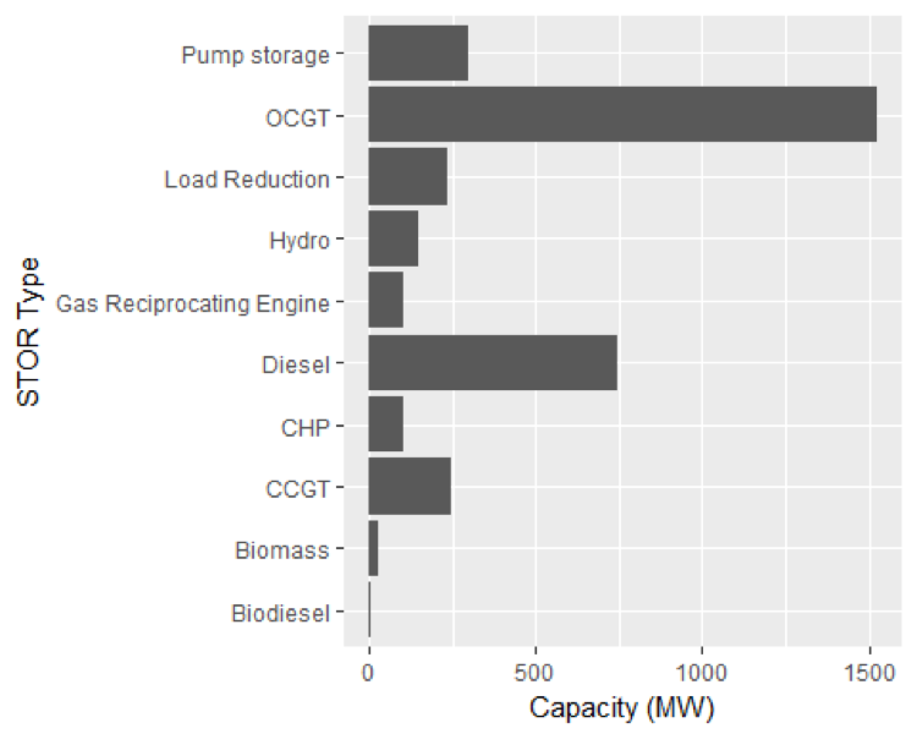
To return grid frequency back to normal, fast reserve, such as pumped storage, is able to respond within two minutes of the initial drop in frequency and starts to return grid frequency back to its nominal frequency [
2]. Fast reserve is expected to operate no longer than approximately 20 minutes and beyond this time period Short Term Operating Reserve (STOR) must begin to take over from fast reserve and provide a longer term replacement to the initially lost generation. As can be seen from
Figure 1, in the UK STOR is dominated by gas (Open Cycle (OC) and Closed Cycle Gas Turbines (CCGT)) and diesel generators, all of which are carbon intensive energy sources.
Systems such as wind turbines and solar panels cannot by themselves provide the ancillary services (inertia, response and reserve) that electricity grids demand since neither systems have large turbines directly coupled to the electricity grid. These ancillary services become increasingly more important in energy scenarios with greater deployment of VRES [
2].
3.2. Frequency Control
Frequency control can be classified into primary and secondary frequency control. The need for frequency control relates to the fact that power demand can never be exactly known in advance and thus there is a certain random variation of demand resulting in frequency fluctuations, typically of less than 20 mHz. Nuclear and conventional power plants operating with primary frequency response have to monitor the frequency on the grid and immediately adapt their level of generation in order to keep the frequency stable at the desired value. Primary frequency control allows short-term adjustment of electricity production and demand in the time frame of about 2 to 30 s after the deviation is observed [
20].
Secondary frequency control acts over longer periods (from several seconds to several minutes), varying the power output of participating plants to restore the grid’s target frequency by calculating an average frequency deviation over a period of time [
20].
3.3. Profile Operation
In order to minimise demands on frequency control and more readily address imbalances in demand and production, some plants, including NPPs, are required to undertake profile operation. The required profile operation a plant must undertake is determined by the grid operator and the utilities based on a forecast of the demand. The ramp rates in profile operation can vary from around 1% per minute up to 5% per minute; however, generally slower ramps (∼1% per minute) take place [
20,
21]. Typical profiles are outlined in
Figure 2.
3.4. Load Following
Load following, as defined earlier, is a fairly rare occurrence with profile operation and frequency control, coupled with reserve units (such as gas power plants and pumped hydro) able to generally accommodate the daily variations in power changes. The changes in power associated with load following can be similar to profile operation or the plants can be shutdown. In the case of load following the notice period given by the system operator (Réseau de Transport d’Électricité (RTE) in the case of France) to an operator (e.g., EdF) is typically one or two days ahead but can be as low as ∼1 h [
22]. The short notice period is generally not less than a few days because it is normally easy to forecast that there will be mismatch in demand a few days ahead, for instance due to excess production from wind [
22]. In the case of France, the operator is able to provide an approximate estimated load profile for the profile operation a couple of days ahead to the system operator but it is mandatory to submit a day in advance the profile operation for each plant to RTE. The mandatory profile operation submission contains, for each plant, information relating to plant output, the plant’s technical requirements and the increase/decrease balancing offers (relating to changes in power over specified time periods) for the following day. We note that the balancing offers are not always accepted by RTE. Each supplier can update and resubmit the profile operation for the next hour, 24 times during a given day (i.e., each hour over the entire day) but only with the approval of the system operator.
Shorter notice periods (as little as ∼1 h) can occur with load following manoeuvres; however, such events are very rare and are typically associated with faults occurring on the grid, such as a plant tripping. In such situations frequency response and reserve are unable to accommodate the mismatch in supply and demand for more than a few tens of minutes and other plants connected to the system must take action at relatively short notice periods [
22].
4. Current Flexible Operation of Nuclear Power Plants
The attributes associated with load following and profile operation pertain to: ramp rates, minimum power levels and restart times. Some of these key attributes for nuclear and fossil-fired power plants are summarised in
Table 1 using data from the international literature. In this section, these limits and the relative importance for grid operators are outlined in relation to nuclear power plants. It is worth noting that the UK experience with PWRs (as also noted in
Section 4.3) is with ramp rates during power operation at no more than 1%/minute [
21]. Note that the data in
Table 1 appears higher than other literature [
20], the authors’ believe this relates to the fact that
Table 1 pertains to the German experience with Konvoi plants—information in the open-literature has these amongst the highest ramp rates of all PWRs.
4.1. Ramp Rates
Whilst ramp rates are useful discriminators between different power systems it must be noted that the importance of ramp rates relating to electricity system reliability is highly dependent on the level of predictability of electricity supply and demand. The easier it is to predict any mismatch in supply and demand, the easier it is to schedule a means to counteract a predicted mismatch, such as calling upon pumped storage, gas and/or interconnectors.
Demand is generally easier to predict and many forms of energy supply are also fairly predictable, including nuclear, gas and wind—current wind forecasting is sufficiently accurate over time horizons up to a few days [
24]. However, solar PV is much more challenging to predict due to the sensitivity and challenges associated with accurately predicting cloud coverage and mass [
25,
26]. Therefore, the importance of ramp rates will be dependent on the level of solar PV connected to the grid. In the case of the UK, with its relatively low solar fluence, ramp rates above what are already achievable are likely to be of limited value. This is supported by UK upper forecasts for solar PV penetration in the year 2050 which are around 140 TWh/yr [
1], whereas for comparison, offshore wind upper forecasts are much higher at around 430 TWh/yr [
1].
4.2. Startup Ramp Rates
In nuclear plants, the limitations on startup ramp rates are dominated by limitations relating to fuel failure concerns. Fuel rod failures, i.e., a breach in the cladding that retains the hazardous fission products, can arise during rapid reactor power increases at the beginning of the cycle, with the probability of failure being sensitive to the rate at which the power increases. In particular, Light Water Reactors are susceptible to fuel rod failure after shutdown related to refuelling, which is thought to be because handling operations allow pellet fragments to relocate within the fuel rods. If trapped between fuel pellet and cladding, the relocated pellet fragments can impose large localised stresses in the cladding. To limit the extent of this stress concentration, very slow ramp rates—that is, power increases of ∼3% per hour above a threshold power level—are prescribed to minimise the likelihood of clad failure during reactor startup [
27]. Below the threshold value (which can be as high as 30%), the ramp rates are significantly less restrictive (e.g., ∼15% per hour) [
27].
There is additional time required in a start-up procedure due to certain procedural hold points that take place at intermediate power levels in PWRs. These procedural hold points must be adhered to during a typical restart and are summarised in
Table 2.
Taking into account the hold point durations and the ramp rates between the hold points (varying from ∼3% of nominal power per hour to ∼15% of nominal power per hour), the whole process to take the reactor back to nominal power after a refuelling shutdown can take 72 to 100 h. Startup rates after a shutdown without refueling can be faster than the 3% per hour, with rates as high as 10% per hour [
21]. In addition, typical manoeuvring rates during power operation can be much faster than the startup rates described here, as outlined in the next section.
4.3. Ramp Rates During Power Operation
Ramp rate limits during power operation are in place to reduce the likelihood of fuel rod failure. The likelihood of fuel failure is greatly increased in situations where the pellet-clad thermo-mechanical equilibrium is perturbed. Hence, large changes in reactor power output over relatively short periods of time can result in fuel failure. Therefore, power manoeuvres can significantly increase the likelihood of fuel failure if not carefully controlled.
During power manoeuvres fuel rods are susceptible to failure from a phenomenon referred to as Pellet-Clad Interaction (PCI) [
28]. PCI failures occur due to mechanical and chemical interactions between the zirconium-based cladding material and the fuel pellets, the latter of which will contain chemically aggressive fission products once energy has been generated within the fuel. Hence, ensuring PCI failure does not take place results in strict limitations on the speed of load following operations.
The initial pellet-clad gap is present to accommodate the diameter increase of the fuel pellets, due to thermal expansion and swelling (as a result of fission product accumulation), during irradiation. The closure of the gap due to pellet thermal expansion and swelling is accelerated by clad creepdown—that is, by compressive creep of the cladding due to the high pressure coolant surrounding it.
Once the pellet-clad gap has closed, any further expansion/swelling of the fuel pellets, for instance due to an increase in power, will lead to hard mechanical interaction between the pellets and the cladding material (that is to say, an increase in clad stresses). However, since the clad has significant ductility, mechanical interactions alone are unlikely to result in failure of the cladding. It is the production and release of chemically aggressive fission products during power changes, which react with the cladding material and weaken it, which makes the cladding material susceptible to failure from mechanical interactions (via cracking); this is the reason for PCI failure being the dominant failure mechanism during load following manoeuvres.
Of all the various power manoeuvre scenarios, the one most likely to result in PCI failure is so-called Extended Reduced Power Operation (ERPO). ERPO can result in reactors operating at powers of around 30% of nominal power for periods of time ranging from several days to several months [
29]. Utilities can be forced to operate at reduced power either due to grid constraints (e.g., high priority being given to renewable energy sources) or technical constraints (e.g., loss of performance of cooling towers) [
29]. ERPO results in higher risks of PCI failure as: (a) initially the pellets will shrink because of thermal contraction as the reactor power decreases, causing the pellet-clad gap to reopen; (b) if sufficient time passes then shrinking of the pellets is followed by clad creepdown. The cladding will then be in a state where a sustained period of rapid pellet expansion will result in considerable stress imposed on the cladding.
Rapid thermal expansion of the pellet can arise, for example, during an operator-induced ramp that returns the reactor to full power from its low power state in a very short period of time, which is then followed by a frequent fault overpower transient [
30]. We note that frequent faults are defined as incidents with moderate frequency (of the order of 10
/year/reactor) which can occur any time during normal plant operation.
If operator-induced ramp rates were too high then in the presence of a frequent fault overpower transient there is a considerable risk of PCI failure taking place. Hence, most utilities do not increase reactor power at a rate above 5%/minute during load following manoeuvres based on information in the international literature. UK experience with the currently operating PWR system is based on much smoother changes, with ramp rates during power operation no faster than 1%/minute [
21].
4.4. Minimum Power Output
The minimum power a power plant can operate at is one of the most important characteristics in relation to grid services, since allowing the plant to operate at low power levels ensures the plant does not need to be shutdown and can still provide services relating to inertia and frequency response. The minimum power outputs for nuclear power plants are broadly similar to those of fossil-fired power plants, as summarised in
Table 1. However, for a nuclear power plant the minimum power levels allowable during power manoeuvres varies as a function of time. During the first 65% of the fuel cycle, power manoeuvres are allowed from 100% of nominal power to around 25% of nominal power. Then, power changes are gradually reduced from 25% to 80% of nominal power since the limited excess reactivity and corresponding low boron concentrations limit the extent of power manoeuvres; in particular, the last 20% of the fuel cycle is limited heavily by the ability to reduce boron concentration as outlined in
Section 5 [
31].
As
Table 2 indicates, it is possible to operate a nuclear plant at power levels as low as 10%; however, the minimum power output (as with many conventional power plants) is around 20% (see
Table 1). It is unusual to operate a nuclear plant as low as 10% for extended periods of time. The reason for not going below 20% of nominal power is unclear but could be due to a number of reasons, including [
21]:
uncertainties regarding plant stability at such low power levels;
invalidation of assumptions in the safety case; and/or
possibility of undergoing a transient overshoot under certain fault sequences when starting from a lower power level.
4.5. Restart Times
In the event a plant experiences an unplanned outage or must be shutdown as part of a load following requirement, then the time it takes to restart the plant is also an important attribute. Being able to call upon a shutdown plant at short notice is envisaged to significantly help address imbalances in production and demand, particularly in scenarios with high VRES [
2].
Published data by Siemens for nuclear power plant restart times are outlined in
Table 3, with coal and combined-cycle gas plant restart times included as comparators. An important aspect not captured in
Table 3 is that, in the event of an unplanned outage, restart times are often limited by the need to understand the event that caused the unplanned outage before the plant can be brought back online, which can significantly prolong the startup time [
21]. To the authors’ knowledge, based on international experience to date, shutdowns related to load-following manoeuvres do not have extra regulatory requirements compared with those associated with startup partway through cycle (i.e., startup without refuelling).
An important point to note is that the nuclear plant data in
Table 3 indicates much more aggressive operational schedules than is typical based on UK experience. Currently, cold startup times are usually around 80 to 100 h as noted in
Section 4.2. Furthermore, the hot and warm startup times in
Table 3 are relatively fast compared with UK experience, where hot and warm startup times are significantly longer (closer to 10 h) assuming the turbine is already synchronised [
21].
5. Reactor Physics Considerations on Flexible Operation
As mentioned in previous sections, there are a number of reactor physics constraints that impact power manoeuvrability. These constraints relate to reactivity control mechanisms and the spatial and temporal behaviour of key fission products as outlined in this section.
5.1. Reactivity Control
In PWRs, there are normally two reactivity control mechanisms: (i) control rods; and (ii) soluble boron in the primary coolant. Routine reactivity control is carried out by varying the concentration of boron and therefore the amount of neutron absorbing B in the coolant, with less reliance on control rods (CRs), to minimise adverse impact on core power distribution. The main use of control rods during power operation is to control the axial power distribution in the core. The power level often exerts a very strong influence over the axial power distribution/shape; so given that many plants operate within a strict allowance “window” of axial shape, control rod insertion is necessary to keep the plant within the window.
As the core is most reactive at the beginning of each ∼18 month fuel cycle, when around 30–45% of the fuel assemblies contain fresh fuel, the coolant contains a relatively high concentration of boron (around 1600 ppm) to accommodate excess reactivity and achieve a critical configuration. The critical boron concentration in the coolant then decreases by around 3 ppm per day until it falls below ∼10 ppm, at which time the reactor must be shutdown and refuelled.
During a power manoeuvre the reactor can be controlled using a combination of variations in boron concentration and control rod movements. The reactor operator can opt to favour control rod movements over boron concentration variations or vice versa.
Boron is introduced into the coolant in the form of boric acid (HBO). If the boric acid concentration variation is favoured (in conjunction with control rod movements) the reactor maintains a reactivity reserve enabling a fast return to full power if required (via control rod withdrawal). However, the volume of effluents associated with the use of the Chemical and Volume Control System (CVCS) for boric acid regulation is increased. Conversely, if control rod variation is preferred as a means of reactivity control (in conjunction with smaller boric acid concentration variations) the CVCS effluent production is decreased. However, the reactor may be unable to quickly return to full power if required since the control rods could already be fully withdrawn (in order to compensate for negative reactivity introduced by xenon build-up).
Variation in the boric acid concentration or control rod movements is used to compensate for xenon-135 build-up when reducing the reactor power during power manoeuvre. Xe is an extremely strong neutron absorber, primarily produced via beta decay of the iodine-135 fission product. I has a 6.6 h half-life, so after a power reduction the production of Xe continues via I decay, but the removal mechanism (neutron absorption by the Xe) decreases since the neutron flux is lower at the lower power level. The net result is an increase in Xe concentration which must be compensated for during load follow manoeuvres by either a decrease in boron concentration or control rod withdrawal. It should be noted that in the event of a power reduction, there will almost certainly be some control rod insertion, with the subsequent control of xenon relying on control rods or soluble boron. Both reactivity control mechanisms become more limited towards the end of cycle, when the excess reactivity is almost exhausted.
5.2. Returning to Power After Reactor Shutdown
The previous section mentions the negative reactivity effect of Xe build-up following a decrease from full to partial power. Similarly, when a reactor is shutdown, Xe continues to be produced via beta-decay of I. The Xe concentration reaches a maximum after ∼11 h. If the reactor needs to be restarted during this period it must contain sufficient excess reactivity to overcome (or “override”) the negative reactivity introduced by Xe neutron absorptions. Conventional GWe-class PWRs possess this excess reactivity enabling a restart even during peak xenon; however, there may be limitations towards the end of a PWR’s operating cycle.
Note that a typical commercial PWR would take approximately 1 h to go from hot zero power standby conditions (e.g., immediately after a trip) to full power and ∼80 h to go from cold zero power conditions (e.g., after refuelling) to full power [
27]. However, in the instance of a reactor trip, whilst it is possible to restart the system relatively quickly, it is necessary to understand the cause of the trip before taking the system back to full power. Often discovering what caused the trip is the largest contributor to prolonging the restart of the nuclear power plant.
5.3. Stability to Xenon Oscillations
The previous section discusses the increase in Xe concentration which occurs following a decrease in reactor power. Similar effects can be observed on a local level as a result of control rod insertion. If a control rod is partially inserted in a PWR (e.g., during a power manoeuvre) the neutron flux increases towards the bottom of the core and decreases towards the top where the control rods absorb neutrons. The concentration of Xe will then decrease towards the bottom of the core due to increased neutron capture. Conversely, the concentration of Xe will increase towards the top of the core due to the lower neutron flux and the associated decrease in neutron capture. This effect results in a skewing of the axial power distribution towards the core bottom.
As the core continues to undergo fission, the distribution of Xe’s precursor, I, evolves such that less I is produced at the top of the core relative to the bottom of the core. Eventually, this results in less Xe at the top of the core relative to the bottom, thereby skewing the power distribution towards the top of the core. Therefore, there is an axial power oscillation set up due to a Xe transient for a period of approximately a day.
The axial power distribution tends to be inherently unstable in large PWRs (due to the core dimensions being much greater than the neutron migration area) in response to these axial xenon oscillations in that, if left unchecked, the power swing will grow in magnitude, potentially leading to fuel failures due to excessive fuel rod powers [
32]. Measures are therefore taken to dampen the oscillations via additional control rod movements and by altering the soluble boron concentration, thereby ensuring the reactor operates within all constraints (e.g., axial offset, inlet and outlet temperatures). Soluble boron is used with control rods to compensate for reactivity changes associated with the movement of control rods. UK experience with PWRs has shown that the axial xenon oscillations naturally reduce in magnitude—apart from in the first fuel cycles [
21]. However, this reduction is relatively slow (over the course of days); hence, the operators take positive action rather than relying on the inherent decay of xenon oscillations.
In smaller reactors, e.g., Small Modular PWRs (SM-PWRs), the shorter active core lengths (e.g., ∼2 m compared with the ∼3.5 m height of a conventional GWe-class PWR) will result in a reactor that is more stable to axial xenon oscillations, which is advantageous during power operation [
33]. In addition to the small active core length, some SM-PWRs intend to operate without soluble boron, which is discussed in the next section.
5.4. Soluble Boron Free Operation in SM-PWRs
SM-PWRs that operate without soluble boron present in the primary coolant during operation (for example, the SMR-160 [
34], CAREM [
35] and SMART [
36] systems) can benefit from the following operational advantages [
37]:
Elimination of a whole series of potential accident scenarios related to uncontrolled boron dilution;
The creation of a far simpler (and therefore cheaper to construct, maintain and operate) Chemical and Volume Control System (CVCS) by removing the need to accommodate boron chemistry control within the CVCS; and
Improved load following characteristics, especially towards the end of the fuel cycle, since boron dilution rates no longer restrict power changes.
However, operating an SM-PWR without soluble boron does exhibit drawbacks related to:
Poorer uranium utilisation as the concentration of neutron absorbing boron can no longer be readily adjusted via dilution throughout the fuel cycle;
Less uniform core power profiles; and
Increased complexity, and therefore cost, in core design associated with the need for more control rods and control rod drive mechanisms to control reactivity throughout cycle length and far greater core heterogeneity.
In large PWRs, the above drawbacks tend to favour the operation of the reactor with boron present in the primary coolant. Some SM-PWRs vendors aim to take advantage of the lower power density of the reactor core (compared with conventional GWe-class PWRs), which permits less uniform core power profiles as the fuel can now withstand elevated power peaking factors [
32]. However, it is still necessary to limit the extent of power variations in the core by employing more variation in the fuel pellet constituents by altering the fissile and burnable poison concentrations radially and axially (increased heterogeneity). This greater variation in fuel make up will have a negative impact on manufacturing costs as a larger number of pellet types must be manufactured. In addition, with the increased core heterogeneity there is a greater risk of fuel loading errors occurring.
There is also the potential to use alternative burnable poisons to the conventional Gd
O
used in most LWR fuel today to compensate for the lack of soluble boron reactivity control and reduce the reliance on control rods [
38]. Er
O
is one alternative burnable poison that has been considered for cores without soluble boron and that has already been employed in commercial PWRs [
37]. However, experience is limited to relatively low concentrations of Er
O
(around 2 wt.%) and there will be an associated economic cost due to the residual poison penalty.
The combination of a shorter active core length (which makes the core less susceptible to xenon oscillations) and operation without soluble boron, will enable SM-PWRs that adopt such core design strategies to offer improved power manoeuvrability relative to larger GWe-class PWRs. Moreover, there is the potential to improve the power manoeuvrability in both large and small PWRs via a more significant means than the elimination of soluble boron and reduced susceptibility to xenon oscillations, namely the use of condensers to manage large rapid power changes as detailed in
Section 7.
6. Other Considerations When Operating Plants Flexibly
Another failure mechanism that can occur during repeated variations in fuel rod powers is fatigue failure. Fatigue failure occurs when damage accumulates in the material due to repeated cyclic loading that may be well below the yield point for the material of interest.
Repeated power manoeuvres, where the cladding is repeatedly exposed to varying loads caused by pellet expansion and contraction as powers increase and decrease, can result in fatigue failure of the cladding [
39]. Fatigue failure is dependent on both the amplitude of the applied stress change and the number of cycles, with larger stress change amplitudes requiring fewer cycles for fatigue failure to transpire relative to smaller stress change amplitudes. However, even though PWR fuel has been exposed to large variations in power over many cycles in commercial reactors (with power variations between 25% and 100% occurring repeatedly throughout rod life in French PWRs [
20]), fatigue failure has not been observed. PCI failure is far more likely, and therefore places more burdensome limits on reactor operation than those resulting from fatigue failure.
The limitations imposed during load following manoeuvres (i.e., the rate and magnitude of power changes) to ensure fuel rod failures do not occur are sufficiently restricting that large components have not been observed to suffer fatigue failure due to load following operation. (Currently, large components in PWRs are acknowledged to be able to withstand 200 cycles of load following operation per year over their operational lifetime (60 years) without impacting their longevity [
20].) It seems unlikely that a utility would operate a reactor outside of these limitations, but if the rate and magnitude of power changes were to increase, and/or the number of cycles were to increase, then there is the risk that large components may require more frequent replacement.
For small components, such as valves, there is some impact of load following on the need to increase their replacement rate [
20]. However, the impact of load following on decreasing a unit’s availability factor is very small (1–2%) [
20].
7. Alternative Means to Provide Large Rapid Power Changes
In the previous sections the ability to improve power manoeuvrability of nuclear plants has focused on understanding the reason behind the limitations (such as boron dilution rates) and where possible considering mechanisms to improve or remove constraints (for instance, relying more on control rods as a means to control reactivity without the reliance on soluble boron). However, greater gains in power manoeuvrability can be achieved by considering more fundamental changes in how to provide rapid power changes. One option for large and small PWRs would be to rely on the use of condensers to enable large power changes, whilst minimising disturbances on the reactor power distribution and associated negative impacts on fuel (namely PCI) and avoiding the use of control rods and soluble boron. Another option that relates to SM-PWRs that are co-located would be to adjust the output of individual plants, including shutting down certain plants on site, to enable rapid power changes.
The use of condensers to allow for large rapid power changes would be based on the turbines running at a lower load and the rest of the steam being passed through the steam dump system into the condenser. This assumes that a suitable control system would be able to distribute steam between the turbines and the steam dump system so as to give rapid changes in output without disturbing the reactor. However, whilst this mode of operation would allow for rapid changes in power, there appears to be limited international experience operating an LWR system in this manner. One potential issue with this process in the current design of PWRs is that current LWRs have to account for a potentially severe fault transient associated with the rapid cooldown of the core if the steam dump valves were to fail open at power [
21]. To avoid the possibility of steam dump valves failing in the open position, interlocks are employed which prevent the valves opening unless certain thresholds are met in terms of sudden loss of load (e.g., generator load rejection).
In the case of a GWe-class PWR the condensers can nominally handle around 60% of the main steam flow and thus 60% of the power generated under full power [
21]. Hence it is conceivable that the core could be operated at around 40–50% of power with the turbine bypassed to result in no net electricity generation. The core could be relatively quickly returned to power, noting the higher ramp rates achievable at power levels above 50%, see
Table 1. In addition, the amount of steam bypassed into the condenser could be very quickly used for power production if required. However, this assumes steam parameters in the turbine and condenser can be adequately controlled over the time period this operation is performed. This would need to be confirmed via detailed system code calculations and optimisation. There would also be concerns relating to continued operation of the condenser in this domain for long periods of time, which is outside of existing operational experience and the design conditions (e.g., higher inlet pressures as well as temperature).
It is important to note the considerable challenges of undertaking an operating regime based heavily on condensers to improve power manoeuvrability in an existing plant due to: (1) the potential need to make modifications in an already built plant; (2) changes to the operating regime of an already existing and licensed facility; and (3) changes to the safety case. The latter item would very likely be the most challenging since modification to the plant and how it operates would need to carefully consider the impacts of the required changes on many other safety systems. This could potentially invalidate a number of assumptions in the safety case and/or the need to modify safety related interlocks and protection systems. For these reasons, the use of condensers to improve power manoeuvrability is likely to only be adopted in new plant designs, where the above challenges are greatly reduced, since the required changes would be taken into account as part of the design evaluation. A key point to note is that the operation of nuclear plants is inherently conservative since moving to a new operational regime would require detailed assessment of the safety implications. This will be made more difficult by the lack of experience and the potential for failure mechanisms to occur in one of the systems within the nuclear plant associated with the new operating regime.
Some SM-PWRs envisage multiple plants located on one site, which could allow for plants on site to be shutdown at short notice and other plants to operate at reduced power. For plants with multiple units, there is no clear preference between operating many plants at part load vs. having some plants shutdown. The suitability of the two operating regimes will be dependent on how long the decrease in electricity demand could last (hours or days). For relatively short periods of time it may be better to operate certain plants at high power and have others shutdown, since for short periods of time the reactors can be brought back online relatively quickly as outlined in
Table 3. If there is a need to restart many of the plants after an extended period of time, then it may be preferable to operate many plants at part power (above power thresholds that result in restrictive ramp rates related to PCI) and minimise the number of plants that shutdown, since restarting plants, after extended periods of shutdown, can be a prolonged process and may make it difficult to meet projected electricity demand. There are also other services the plants can offer when online and operating with part-load, namely frequency response and inertia, which may create other drivers to keep units connected to the grid and minimise the number of plants that shutdown. Therefore, the potential advantages associated with smaller co-located plants over large plants is unclear, when factoring the time period the demand change could last for and services related to inertia and frequency response.
8. Conclusions
Nuclear power plants in the UK have not to date been required to operate in flexible response modes, because historically other generating types have been able to meet the limited flexibility demands. This is likely to change in the future because of the changing demands on the grid system and the changing mix of generation types to meet decarbornisation targets. The increasing contribution of Variable Renewable Energy Sources (VRES), amongst other factors and decreasing reliance on gas generation will likely lead to nuclear plants being required to respond more flexibly. This paper has reviewed the technical limitations on ramp rates, restart times and minimum power levels that determine how flexible large and small PWRs can be. Ramp rates are generally of lower importance, assuming the ability to predict in advance any mismatch between supply and demand is possible. With respect to restart times, there are a number of nonreactor specific constraints related to synchronising the plant and performing tests that are difficult to circumvent except by avoiding restarts where possible. Minimum power output is considered to have the greatest impact since it can determine the level to which the power output of the system can be modified to accommodate significant mismatches in supply and demand. Moreover, the lower the minimum power output, the less likely a plant will be required to shutdown for large mismatches in supply and demand.
This report has highlighted that the international community has much more experience in nonstationary operation of nuclear power plants than the UK. Currently, the ramp rates applied in the UK are much lower than the ones outlined in the international literature, with minimum power levels and restart times also being less aggressive. There is a clear reason for this in that there is currently limited demand for flexible operation from nuclear plants. As a result, in the event that flexible nuclear power plant operation becomes necessary, operational experience with rapid power changes and low power operation would have to be developed first, even if the flexibility of the plant has already been envisaged in the design. This is essential to demonstrate the ability of the operator to manage the arising challenges, which will be demanded by the regulator.
There is the potential to operate systems more flexibly via novel operation routes that could allow for more significant gains than the adoption of SM-PWRs that operate without soluble boron and are less susceptible to xenon oscillation, via the use of condensers. However, this poses a number of challenges that require further investigation and optimisation studies to address, in particular concerns related to severe fault mechanisms related to overcooling and concerns regarding condenser performance when operated for prolonged periods of time in this manner. Furthermore, the use of condensers to allow for greater power manoeuvrability is likely to only be adopted in advanced LWR plant designs due to the challenges associated with modifying a plant, its operating regime and most importantly, the effort required to update an existing safety case.
Finally, this study has highlighted the increasing role of nuclear in providing rotational inertia for the grid. With the trend towards increasing VRES and decreasing reliance on fossil plants, nuclear may need to be relied on as the principal contributor to system inertia. Since inertia strongly influences stability, there is a potential role for the nuclear plants to provide inertia as a service to the grid in addition to power generation and flexible response.
Author Contributions
Conceptualisation, A.P.; methodology, A.P.; validation, B.M.; formal analysis, A.P.; investigation, A.P.; writing—original draft preparation, A.P.; writing—review and editing, B.M. and K.H.; visualisation, A.P.; supervision, B.M. and K.H. All authors have read and agreed to the published version of the manuscript.
Funding
This research was funded by the UK government’s Department for Business, Energy and Industrial Strategy, as part of the Nuclear Innovation Programme (Nuclear Facilities and Developing a Strategic Toolkit) grant number 13070002346.
Acknowledgments
The authors would like to gratefully acknowledge input received from Paul Bryce (EDF Energy) and Anes Dallagi (EDF Energy).
Conflicts of Interest
The authors declare no conflict of interest. The funders had no role in the design of the study; in the collection, analyses, or interpretation of data; in the writing of the manuscript, or in the decision to publish the results.
References
- 2050 Pathways Analysis; Technical Report; HM Government: London, UK, 2010.
- Boster, A.; Thomas, H. Managing Flexibility Whilst Decarbonising the GB Electricity System; Technical Report; Energy Research Partnership: London, UK, 2015. [Google Scholar]
- European Utility Requirements for LWR Nuclear Power Plants; Technical Report; EUR: Lyon, France, 2012; Volume 2, Chapter 3.
- Feutry, S. Production renouvelable et nucléaire: deux énergies complémentaires. Revue Générale Nucléaire 2017, 1, 23–28. [Google Scholar] [CrossRef]
- WNA. Nuclear Power Reactors; World Nuclear Association: London, UK; Available online: https://www.world-nuclear.org/information-library/nuclear-fuel-cycle/nuclear-power-reactors/nuclear-power-reactors.aspx (accessed on 14 February 2020).
- Nuclear Energy Factsheets Load following Capabilities of Nuclear Power Plants; Technical Report; SNETP: Paris, France, 2017.
- Dunkelberg, H.; Sondermann, M.; Meschede, H.; Hesselbach, J. Assessment of flexibilisation potential by changing energy sources using Monte Carlo simulation. Energies 2019, 12, 711. [Google Scholar] [CrossRef]
- De Filippo, A.; Lombardi, M.; Milano, M. User-aware electricity price optimization for the competitive market. Energies 2017, 10, 1378. [Google Scholar] [CrossRef]
- Marchiori, F.; Belloni, A.; Benini, M.; Cateni, S.; Colla, V.; Ebel, A.; Lupinelli, M.; Nastasi, G.; Neuer, M.; Pietrosanti, C.; et al. Integrated dynamic energy management for steel production. Energy Procedia 2017, 105, 2772–2777. [Google Scholar] [CrossRef]
- Lindberg, C.F.; Zahedian, K.; Solgi, M.; Lindkvist, R. Potential and Limitations for Industrial Demand Side Management. Energy Procedia 2014, 61, 415–418. [Google Scholar] [CrossRef]
- DECC. The Future of Heating: Meeting the Challenge; Technical Report; Department of Energy and Climate Change: London, UK, 2013.
- DECC. The Future of Heating: Meeting the Challenge—Evidence Annex; Technical Report; Department of Energy and Climate Change: London, UK, 2013.
- DECC. The Future of Heating: A Strategic Framework for Low Carbon Heat in the UK; Technical Report; Department of Energy and Climate Change: London, UK, 2012.
- Burtin, A.; Silva, V. Technical and Economic Analysis of the European Electricity System with 60% RES; Technical Report; EDF: London, UK, 2015. [Google Scholar]
- Bartels, J.; Pate, M.; Olson, N. An economic survey of hydrogen production from conventional and alternative energy sources. Int. J. Hydrog. Energy 2010, 35, 8371–8384. [Google Scholar] [CrossRef]
- Nimtz, M.; Krautz, H.J. Flexible Operation of CCS Power Plants to Match Variable Renewable Energies. Energy Procedia 2013, 40, 294–303. [Google Scholar] [CrossRef]
- Domenichini, R.; Mancuso, L.; Ferrari, N.; Davison, J. Operating Flexibility of Power Plants with Carbon Capture and Storage (CCS). Energy Procedia 2013, 37, 2727–2737. [Google Scholar] [CrossRef]
- ERP. Potential Role of Hydrogen in the UK Energy System; Technical Report; Energy Research Partnership: London, UK, 2016. [Google Scholar]
- Short Term Operating Reserve: Fuel Type Analysis—Season 8.5. Available online: https://www.nationalgrid.com/sites/default/files/documents/STOR%20%20Fuel%20Type%20Analysis%20Summary%20%28By%20Capacity%29%20-%20Season%208.5%20-%20Final_0.pdf (accessed on 18 December 2017).
- Technical and Economic Aspects of Load Following with Nuclear Power Plants; Technical Report; OECD-NEA: Paris, France, 2011.
- EDF. Private communication with P. Bryce, 2018.
- EDF. Private communication with A. Dallagi, 2019.
- Balling, L. Flexible Future for Combined Cycle. Mod. Power Syst. 2010, 30, 61–65. [Google Scholar]
- Wang, X.; Guo, P.; Huang, X. A Review of Wind Power Forecasting Models. Energy Procedia 2011, 12, 770–778. [Google Scholar] [CrossRef]
- Mandal, P.; Madhira, S.T.S.; Haque, A.U.; Meng, J.; Pineda, R.L. Forecasting Power Output of Solar Photovoltaic System Using Wavelet Transform and Artificial Intelligence Techniques. Procedia Comput. Sci. 2012, 12, 332–337. [Google Scholar] [CrossRef]
- Wang, P.; van Westrhenen, R.; Meirink, J.F.; van der Veen, S.; Knap, W. Surface solar radiation forecasts by advecting cloud physical properties derived from Meteosat Second Generation observations. Sol. Energy 2019, 177, 47–58. [Google Scholar] [CrossRef]
- Yagnik, S.; Sunderl, D.J.; Cheng, B.C. Effect of PWR Re-start Ramp Rate on Pellet-Cladding Interactions. In Proceedings of the Cadarache Seminar on Pellet-Clad Interaction in LWR Fuel, Aix-en-Provence, France, 9–11 March 2004. [Google Scholar]
- Paulin, P. Operational constraints related to SCC-PCI. In Pellet-Clad Interaction (PCI) in Water-Cooled Reactors; OECD-NEA: Paris, France, 2016. [Google Scholar]
- Bessiron, V.; Jamet, N.; Gressier, C.; Sautereau, A.; Schuh, K.D.; Paul, T.; Royere, C. AREVA’s PCI Methodologies for PWR Enhanced Plant Maneuverability. In Proceedings of the WRFPM; Atomic Energy Society of Japan: Tokyo, Japan, 2014. [Google Scholar]
- Beguin, S. PCI-Related Constraints on EDF PWRs and Associated Challenges. In Proceedings of the Cadarache Seminar on Pellet-Clad Interaction in LWR Fuel, Aix-en-Provence, France, 9–11 March 2004. [Google Scholar]
- Waeckel, N. General overview of the French effort to address the SCC-PCI issue. In Pellet-Clad Interaction (PCI) in Water-Cooled Reactors; OECD-NEA: Lucca, Italy, 2016. [Google Scholar]
- EPRI. Elimination of Soluble Boron for a New PWR Design; Technical Report; Electric Power Research Institute: Palo Alto, CA, USA, 1989. [Google Scholar]
- Ingremeau, J.; Cordiez, M. Flexblue core design: Optimisation of fuel poisoning for a soluble boron free core with full or half core refuelling. EPJ Nucl. Sci. Technol. 2015, 1, 11. [Google Scholar] [CrossRef]
- SMR-160 Essential Information; Technical Report; Holtec International: Jupiter, FL, USA, 2017.
- Magan, H.B.; Delmastro, D.F.; Markiewicz, M.; Lopasso, E.; Diez, F.; Giménez, M.; Rauschert, A.; Halpert, S.; Chocrón, M.; Dezzutti, J.C.; et al. CAREM prototype construction and licensing status. In IAEA-CN-164-5S01; IAEA: Vienna, Austria, 2014. [Google Scholar]
- Rhamdhani, R.; Prastyo, P.A.; Waris, A.; Kurniadi, R. Neutronics Analysis of SMART Small Modular Reactor using SRAC 2006 Code. J. Phys. Conf. Ser. 2017, 877, 012067. [Google Scholar] [CrossRef]
- Peakman, A.; Owen, H.; Abram, T. The core design of a Small Modular Pressurised Water Reactor for commercial marine propulsion. Prog. Nucl. Energy 2019, 113, 175–185. [Google Scholar] [CrossRef]
- Peakman, A.; Grove, C.; Fitzgerald, K.; Gregg, R. Development of an equilibrium loading pattern and whole-core fuel performance assessment in the Advanced Boiling Water Reactor (ABWR) with UO2 and U3Si2 fuels. Prog. Nucl. Energy 2019, 117, 103053. [Google Scholar] [CrossRef]
- O’Donnel, W.; Langer, B. Fatigue Design Basis for Zircaloy Components. Nucl. Sci. Eng. 1964, 20, 1–12. [Google Scholar] [CrossRef]
© 2020 by the authors. Licensee MDPI, Basel, Switzerland. This article is an open access article distributed under the terms and conditions of the Creative Commons Attribution (CC BY) license (http://creativecommons.org/licenses/by/4.0/).


