Article

Numerical Study on the Elastic Deformation and the Stress Field of Brittle Rocks under Harmonic Dynamic Load

1
Institute of Petroleum Engineering, Northeast Petroleum University, Daqing 163318, China
2
Centre for Applied Dynamics Research, School of Engineering, University of Aberdeen, Aberdeen AB24 3UE, UK
*
Author to whom correspondence should be addressed.
Energies 2020, 13(4), 851; https://doi.org/10.3390/en13040851
Submission received: 30 December 2019 / Revised: 8 February 2020 / Accepted: 11 February 2020 / Published: 15 February 2020

Abstract

:
In order to study the deformation displacement and the stress field of brittle rocks under harmonic dynamic loading, a series of systematic numerical simulations are conducted in this paper. A 3D uniaxial compression simulation is carried out to calibrate and determine the property parameters of sandstone and a model of the cylindrical indenter intruding the rock is proposed to analyze the process of elastic deformation. Four main parameters are taken into account, namely the position on the rock, the frequency and the amplitude of dynamic load, the type of indenter and the loading conditions (static and static-dynamic). Based on the analysis undertaken, it can be concluded that both of the deformation displacement and stress field of the rock change in a harmonic manner under the static-dynamic loads. The frequency and the amplitude of harmonic dynamic load determine the period and the magnitude of the rock response, respectively. In addition, the existence of harmonic dynamic load can aggravate the fatigue damage of the rock and allow a reduction in static load. Our investigations confirm that the static-dynamic loads are more conducive to rock fracture than static load.

1. Introduction

In order to improve the crushing efficiency of hard rocks or some unconventional resources [1], some auxiliary rock-breaking tools, such as axial hydraulic impactor [2], and few emerging rock-breaking methods, such as Resonance Enhanced Drilling (RED) [3,4] and ultrasonic drilling [5,6], have been proposed. There is one thing in common in terms of the working principle that they all apply an additional periodic dynamic load to the rock based on static load to achieve Rate of Penetration (ROP) improvement. Moreover, compared to other kinds of periodic dynamic loads, the dynamic load in the harmonic form which changes in a cosine (or sine) law with time has been proven to be the most effective [7,8]. In short, the dynamic load plays an increasingly important role in rock fragmentation.
The intrusion of indenter into the rock is considered an ideal method to analyze the mechanical problems during excavation, which has been widely used in various engineering fields including oil drilling, mining, tunneling and so on [9,10,11,12]. The interaction between the rock and the indenter has been studied mainly focusing on two aspects: deformation and stress field [13,14,15], and fracture and fragmentation of the rock [16,17,18,19]. Both of them are of great significance to the mechanism research, optimization of operation parameters and process of mechanical tools for rock fragmentation.
At present, a large number of studies on the indenter intrusion process have been proposed for different geometries of indenters such as spherical, pyramidal, conical and flat-ended cylindrical indenters through theoretical, numerical and experimental methods [20,21,22,23]. Elastic mechanics is the most common theoretical approach for studying the deformation and stress field of rocks [24,25,26,27]. The finite element method (FEM), the boundary element method (BEM) and the discrete element method (DEM) are three widely used methods to simulate the indenter intrusion process [28,29,30,31,32]. Many experimental tests have been carried out to verify the theoretical results and explore more complex issues [33,34,35,36]. Based on these studies, a basic understanding of the indenter intrusion process has been developed.
However, most existing research on the indenter intrusion process considers only static load. A few works are conducted under dynamic load, and the impact velocity is the main factor to be considered [37,38,39]. There are few studies on the mechanical behavior of rocks under indenter intrusion with the harmonic dynamic load. Besides, rock often suffers brittle failure under external force due to its internal defects [40,41,42]. When the stress in which the brittle rock is subjected exceeds the fracture strength of the rock, the rock will be instantaneously damaged without exhibiting significant plastic strain, which means that the elastic deformation is the main stage before the rock fracture. As the mechanical properties of the brittle rock at the elastic stage are the key to its fracture, in order to investigate the effect of harmonic dynamic load on the mechanical behavior of rock under indenter intrusion, the elastic deformation and the stress field of the brittle rock under static-dynamic load are analyzed through FE numerical simulation.
The paper is organized as follows. In Section 2, a 3D uniaxial compression simulation is carried out based on the experimental data to calibrate the rock model. Then, the 3D FE model is established and the mesh size sensitivity analysis is conducted to ensure the accuracy of results in Section 3. Finally, the effects of loading conditions, parameters of the dynamic load and the type of indenter on the deformation displacement and stress field of the brittle rock are analyzed and discussed in Section 4. Finally, the conclusions of this study are presented in Section 5.

2. The 3D Uniaxial Compression Simulation

The lithology used in the simulation, through this study, is sandstone. The 3D uniaxial compression simulation is firstly carried out to calibrate and determine the property parameters of the sandstone adopted in the numerical simulation according to the uniaxial compression experiment. The FE model consists of a cylinder in the size of Ø54 mm × 116 mm and two rigid disks in the size of Ø108 mm × 0.5 mm, as shown in Figure 1a. A fully fixed constraint is applied to the lower disk and a compressive displacement load of 5 mm is applied to the upper disk which only has a z-direction degree of freedom. Finally, the sandstone undergoes the same shear fracture as in the experiment, as shown in Figure 1b.
The stress–strain curve of sandstone from the numerical simulation with a good match with the experimental results is obtained (as shown in Figure 2), through a series of parameter calibrations. Thus, the property parameters of sandstone adopted in the simulation are determined, as shown in Table 1.
In addition, it is observed through the experimental and numerical results that the sandstone has obvious brittleness. When the applied stress reaches the fracture strength of the formation, it is damaged directly without plastic deformation. Therefore, to improve the calculation efficiency, only the elastic parameters of sandstone are set and its plastic and damaged properties are ignored in the following simulations.

3. Numerical Model of Indenter Intrusion

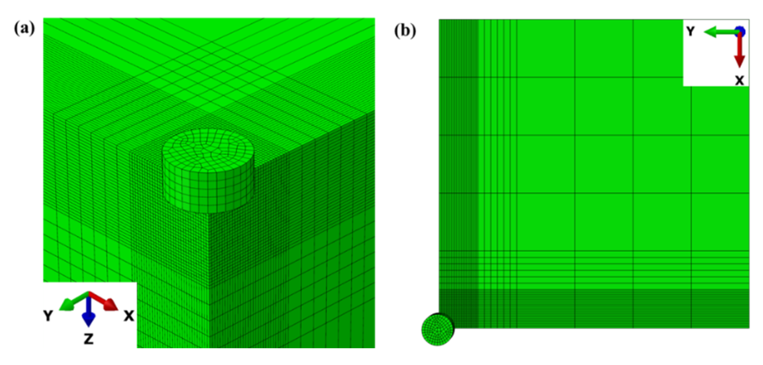
3.1. The 3D Finite Element Modeling

The deformation displacement and the stress field of the rock under static and static-dynamic loads are analyzed through the process of the cylindrical indenter intruding the rock. The 3D FE model is shown in Figure 3a, where the tool steel indenter is a cylinder with a diameter of 5 mm, and the rock is a cube of 100 mm × 100 mm × 100 mm. The rock is much larger than the indenter so that the influence of its boundaries on the deformation displacement and the stress field can be ignored. Since the geometric shape and force distribution of the model are symmetric, a quarter of the model is adopted as shown in Figure 3b, in order to reduce computational time. Besides, the cylindrical indenter is regarded as a rigid body, on which a reference point is set to bind with it, limiting its freedom only in the Z-direction. Meanwhile, fully fixed constraints are applied to the rock bottom, and symmetrical constraints which are perpendicular to X and Y axes are applied to the A and B side of the rock, respectively.

3.2. Parameter Settings

The property parameters of the rock and the indenter used in the simulations are shown in Table 2, assuming the indenter as a rigid body, the rock only with its elastic stage in this numerical study.
In the simulation, the static load of 1 kN is applied and the influence of dynamic load on the deformation displacement and the stress field of rock are analyzed by changing its frequency between 100 Hz and 150 Hz and its amplitude between 0.5 kN and 1 kN.

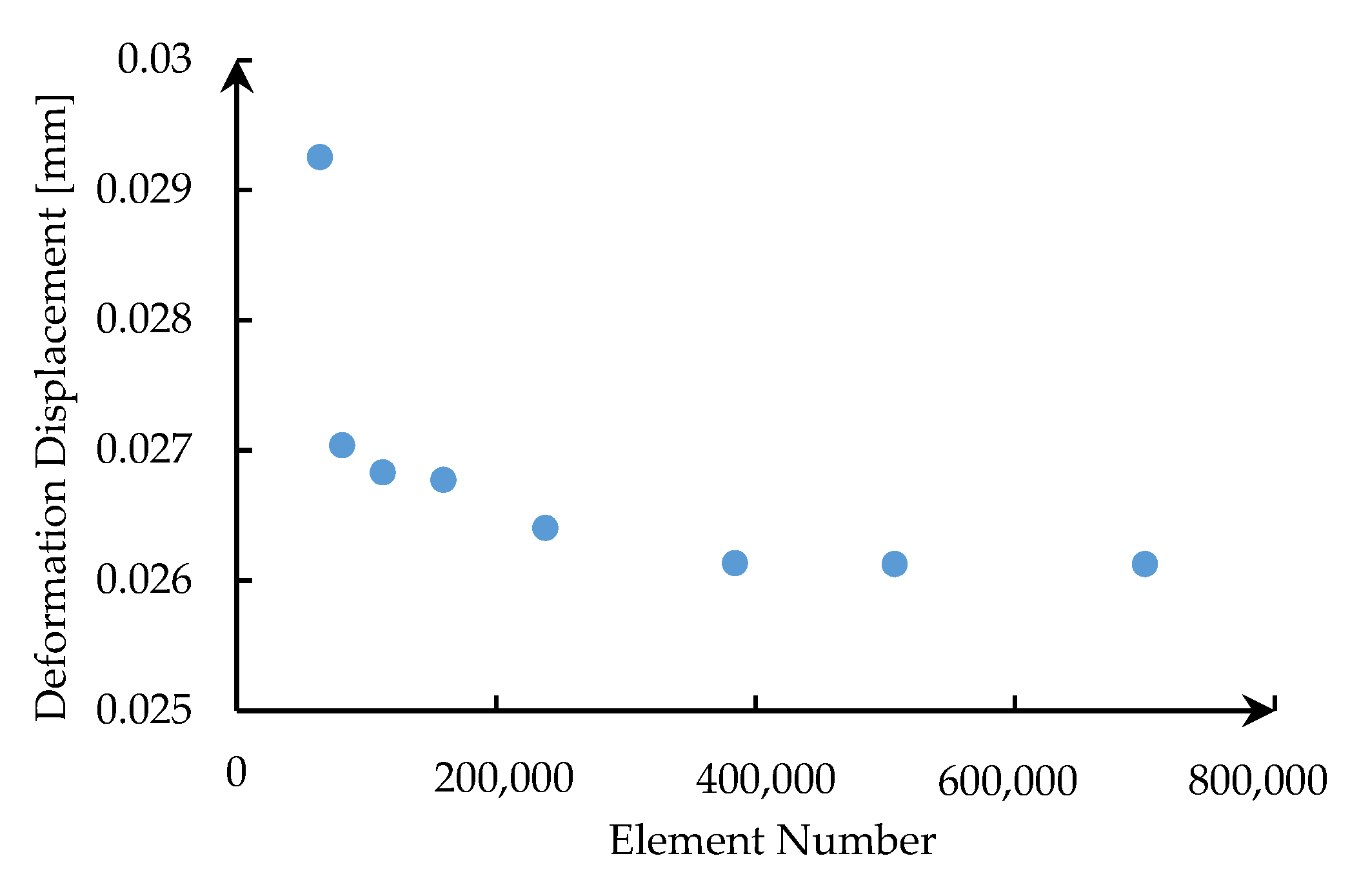
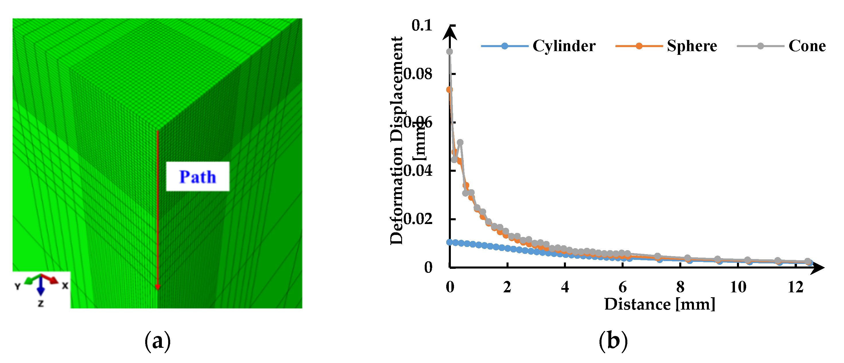
3.3. Mesh Size Sensitivity Analysis

As the results of the FE model are highly sensitive to mesh size, mesh size sensitivity analysis is conducted to minimize the influence of the grid size on the results. The model was run with various numbers of elements and the deformation displacements of the same point on the rock surface under static load are compared to each other.
As displayed in Figure 4, when the number of elements exceeds 400,000, the deformation displacement of rock starts to converge and tends to a constant value. At this point, the corresponding mesh size is 0.25 mm. Meanwhile, based on the interaction area between the indenter and the rock obtained from the simulation results, in order to maximize the computational efficiency, the FE model is meshed, as shown in Figure 5. The grid is 0.2 mm in the area below and adjacent to the indenter, 1 mm in the next area and 10 mm in the area away from the indenter.

4. Results and Analysis

4.1. Influence of the Position on the Rock

A static load of 1 kN and a harmonic dynamic load with an amplitude of 1 kN and a frequency of 100 Hz are applied to the rock, and the deformation displacements of the rock under the static-dynamic loads are compared. In Figure 6a, the contact area between the cylindrical indenter and the rock has been circled with a dotted red line. Four points on the surface of the rock have been selected, among which points A and B are below the indenter, point C is near the indenter and point D is away from the indenter.
Figure 6b depicts the relationship of deformation displacement versus time at different positions on the rock surface. It can be seen from Figure 6b that under the combined action of static load and harmonic dynamic load, the deformation displacement of the rock presents a stable harmonic variation after the initial unstable fluctuation (transient response). With the increase of the distance from the center of the indenter, the deformation displacement of the rock decreases. It should be noted that in the contact area between the indenter and the rock, the deformation displacements of points A and B are very close, and the amplitude of the deformation displacement decreases slightly. However, the deformation displacements of point C and D decrease significantly when the area is outside the indenter.
Previous research results [23] have given that deformation displacement on the rock surface under static load for a cylindrical indenter can be expressed outside the contact area between the indenter and the rock as
w = 4 ( 1 μ 2 ) q r π E [ 0 π / 2 1 a 2 r 2 sin 2 θ d θ ( 1 a 2 r 2 ) 0 π / 2 d θ 1 a 2 r 2 sin 2 θ ]
Within the contact area between the indenter and the rock as
w = 4 ( 1 μ 2 ) q a π E 0 π / 2 1 r 2 a 2 sin 2 φ d φ
where μ and E are the Poisson’s ratio and elastic modulus of the rock, respectively; a is the radius of the indenter, m; r is the distance from the center of the indenter, m; q is the static load per unit area, N/m2. Based on the above-mentioned formulas, it can be also concluded that the deformation displacement on the rock surface under static load decreases with increasing distance from the center of the indenter.
Compared with the static load, the static-dynamic loads are equivalent to adding a dynamic load which changes periodically with time. For a certain moment, it can still be regarded as a static load problem with the superposition of two loads. Therefore, Equations (1) and (2) are still applicable to these static-dynamic loads’ problem, just replace the q with q + q(t), where q(t) is the dynamic load per unit area. That is why similar results are obtained from static and static-dynamic loads conditions.

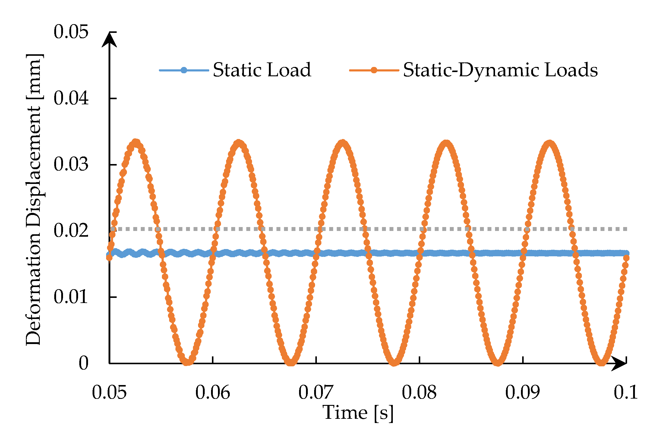
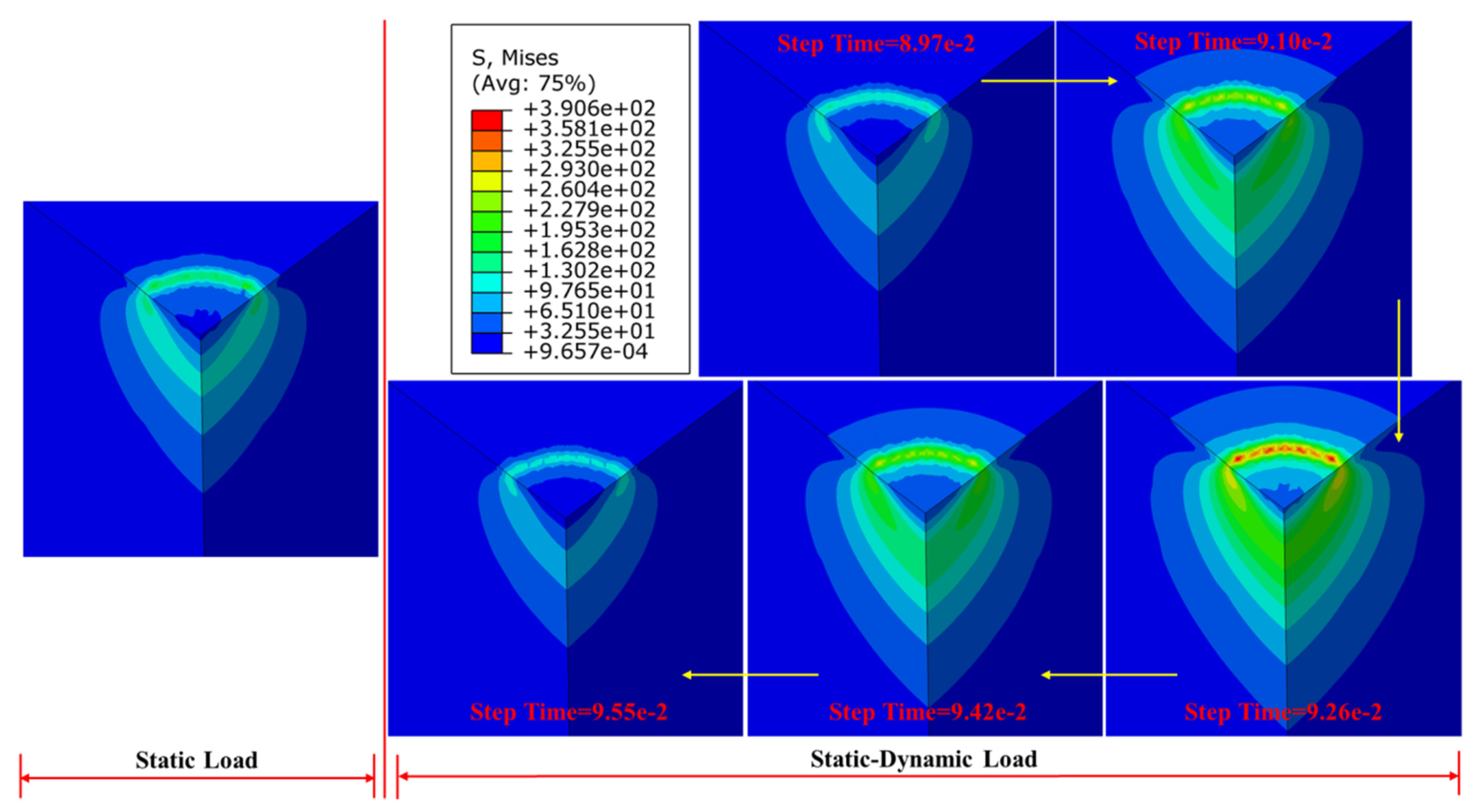
4.2. Static Load vs. Static-Dynamic Loads

Static load and static-dynamic loads are applied to the cylindrical indenter separately, both static loads are 1 kN and the dynamic load is a harmonic load with an amplitude of 1 kN and a frequency of 100 Hz. Then, the deformation displacement and the stress field of the rock under two kinds of loading conditions are compared.
Figure 7 shows the curves of deformation displacement at the same position on the rock surface under two loading conditions. As shown in Figure 7, the deformation displacements of the rock under two types of loads are obviously different, which converges to a constant value under static load and varies in a harmonic form under static-dynamic load, respectively. In addition, there is a grey dotted line representing the failure displacement of the rock in the figure as a reference line, of which the value is determined from the uniaxial compression simulation in Section 2.
By comparing the three curves in Figure 7, it can be seen that at the same position on the rock surface, the deformation displacement of the rock under static load does not exceed its failure displacement which would result in no fracture occurring, while the fracture can occur under static-dynamic loads because of its larger deformation displacement. This also explains why static-dynamic load is beneficial to rock fracture from the perspective of deformation. In addition, we know from Section 4.1 that as the distance from the indenter increases, the deformation displacement of the rock decreases, which is also applicable to static load conditions. We can draw a conclusion from the results in this section that the deformation displacement of the rock under static-dynamic loads is greater than that under static load at the same position of the rock, which means that although the area under the indenter may fracture under both kinds of loading conditions, the static-dynamic loads can work on a wider range than static load in the rock area which is away from the indenter.
The 3D stress contour plots of the rock under two loading conditions are given in Figure 8. As shown in Figure 8, the distribution of the stress field of the rock under static load is stable, and the maximum stress is generated at the boundary of the indenter and a certain depth below the rock. Five representative stress contour plots of the rock in an impact period under static-dynamic loads are shown. It can be seen that the stress field of the rock also presents periodic changes due to the existence of harmonic dynamic load. When the direction of dynamic load is opposite to static load, the stress field of the rock gradually decreases and eventually becomes lower than that under static load. While when the direction of dynamic load is consistent with the static load, the stress field of rock increases and exceeds that under static load. In addition, the response range of the stress field of the rock caused by static-dynamic loads is larger than that under static load. Therefore, it also can be concluded from the perspective of the stress field that when the fracture strength of the rock is between the stress strength under static and static-dynamic loads, the latter is more advantageous to rock fracture.

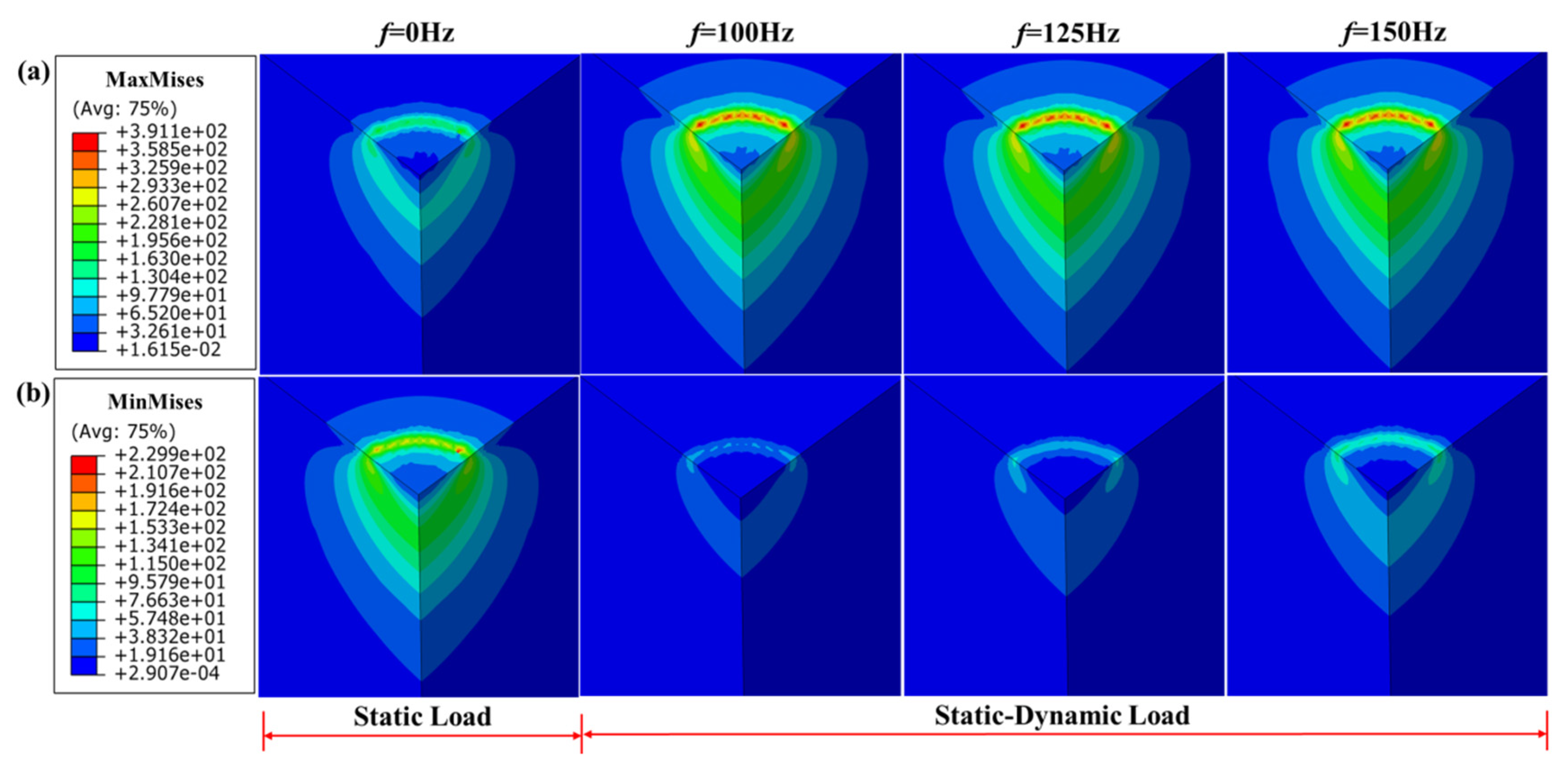
4.3. Influence of the Frequency of Dynamic Load

The frequency of dynamic load is one major parameter that could influence the deformation displacement and the stress field of the rock under the cylindrical indenter. Therefore, a constant static load of 1 kN and a dynamic load of 1 kN with the frequencies of 100 Hz, 125 Hz and 150 Hz, are applied to the rock in the three simulations.
Figure 9 depicts the relationship between deformation displacement versus time at the same position on the rock surface with different frequencies of dynamic load. It is obvious that the variation in the frequency of dynamic load only changes the period of rock deformation response without changing the magnitude of its deformation displacement. Within the same time, the higher the frequency of dynamic load is, the more the reciprocating times of deformation are. Based on the above analysis, it can be further found that even if the deformation displacement of the rock under static-dynamic loads does not reach its failure level, high-frequency dynamic load also promotes the rock fracture, which is due to the high-frequency reciprocating motion will aggravate the fatigue damage of the rock. Actually, the selection of the frequency of dynamic load should also take into account the resonance frequency range of rocks and the allowable range of practical conditions.
Figure 10 shows the maximum and minimum stress of the rock under static-dynamic loads with different frequencies, and compares them with the stress field of the rock under static load, respectively. In Figure 10a, it can be seen that the maximum stress of the rock under static-dynamic loads with different frequencies is greater than that under static load, but the maximum stress is almost the same with the change of the frequency of dynamic load. Similarly, it can be seen in Figure 10b that the minimum stress of the rock is less than that under static load, and its value does not change much, either. Therefore, we can conclude that the variation of the frequency of dynamic load does not affect the amplitude of the stress field of the rock, but static-dynamic loads with any frequency have a better effect on the rock fracture than static load only.
Note that if we do not change the amplitude of load, as expected we do not get any different level of deformation and stress as the model does not consider fracture. Nevertheless, we can still see the significance of the change in frequency, which changes the response period and affects the fatigue life of the rock.

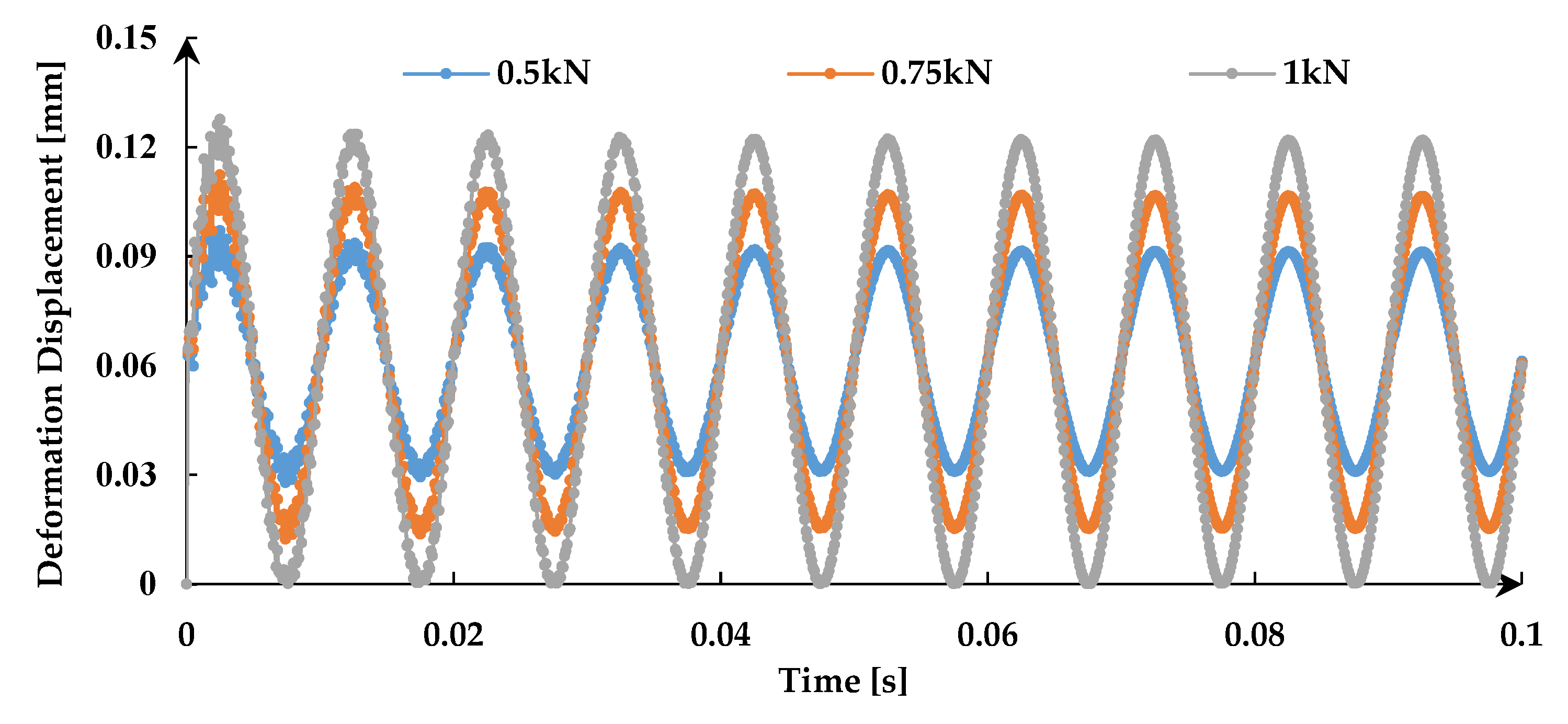
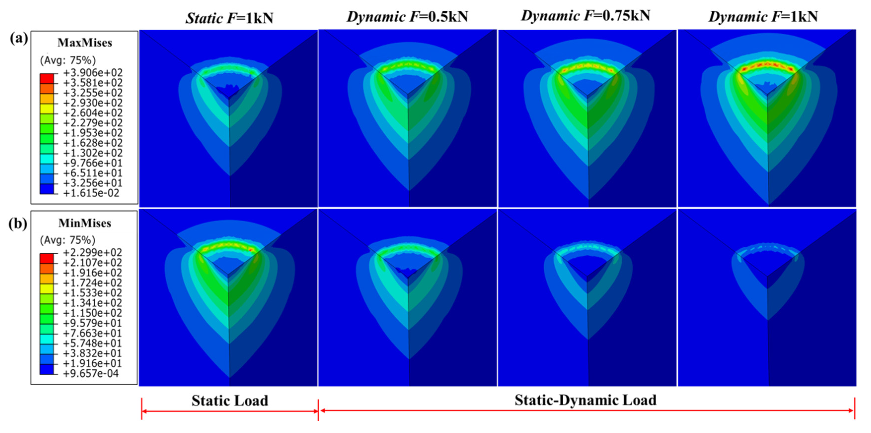
4.4. Influence of the Amplitude of Dynamic Load

The amplitude of dynamic load is another main factor affecting the intrusion effect under the static-dynamic loads. Therefore, a constant static load of 1 kN and dynamic load with a frequency of 100 Hz are adopted, and only the amplitude of dynamic load is set to 0.5 kN, 0.75 kN and 1 kN, to analyze the deformation displacement and stress field of the rock in this section.
The deformation displacement is simulated for the varying amplitude of dynamic load giving the results shown in Figure 11. The magnitude of deformation displacement of the rock increases with the increase of the amplitude of dynamic load, but the frequency of fluctuations of the deformation displacement does not change. The greater the amplitude of dynamic load is, the more serious the deformation of the rock is, which is more conducive to rock fracture. However, it is worth noting that the amplitude of dynamic load cannot be increased optionally, its maximum value needs to be less than or equal to the static load. This is because if the dynamic load is greater than the static load, the indenter would be lifted at some time instead of intruding the rock, which is unfavorable for the rock fragmentation. In addition, it can be also concluded that the rock can be broken even under a smaller static load because the dynamic load would aggravate the deformation of the rock on the basis of static load, which implies that for drilling application, a smaller weight on the bit can be allowed when drilling under the static-dynamic loads.
Figure 12 demonstrates 3D contour plots of the maximum and minimum stress of the rock under static and static-dynamic loads with different amplitudes of dynamic load, respectively. As shown in Figure 12a, the maximum stress of the rock increases with the increase of the amplitude of dynamic load and is higher than that under static load, while in Figure 12b, it can be seen that the minimum stress of the rock decreases as the amplitude of the dynamic load increases, and is lower than that under static load, which means that the amplitude of dynamic load has an effect on the magnitude of the stress field of the rock. It can be also concluded that when the rock does not break under static load, adding dynamic load and adjusting the amplitude of dynamic load can make the stress of the rock exceed its fracture limit and break even if its minimum stress decreases.

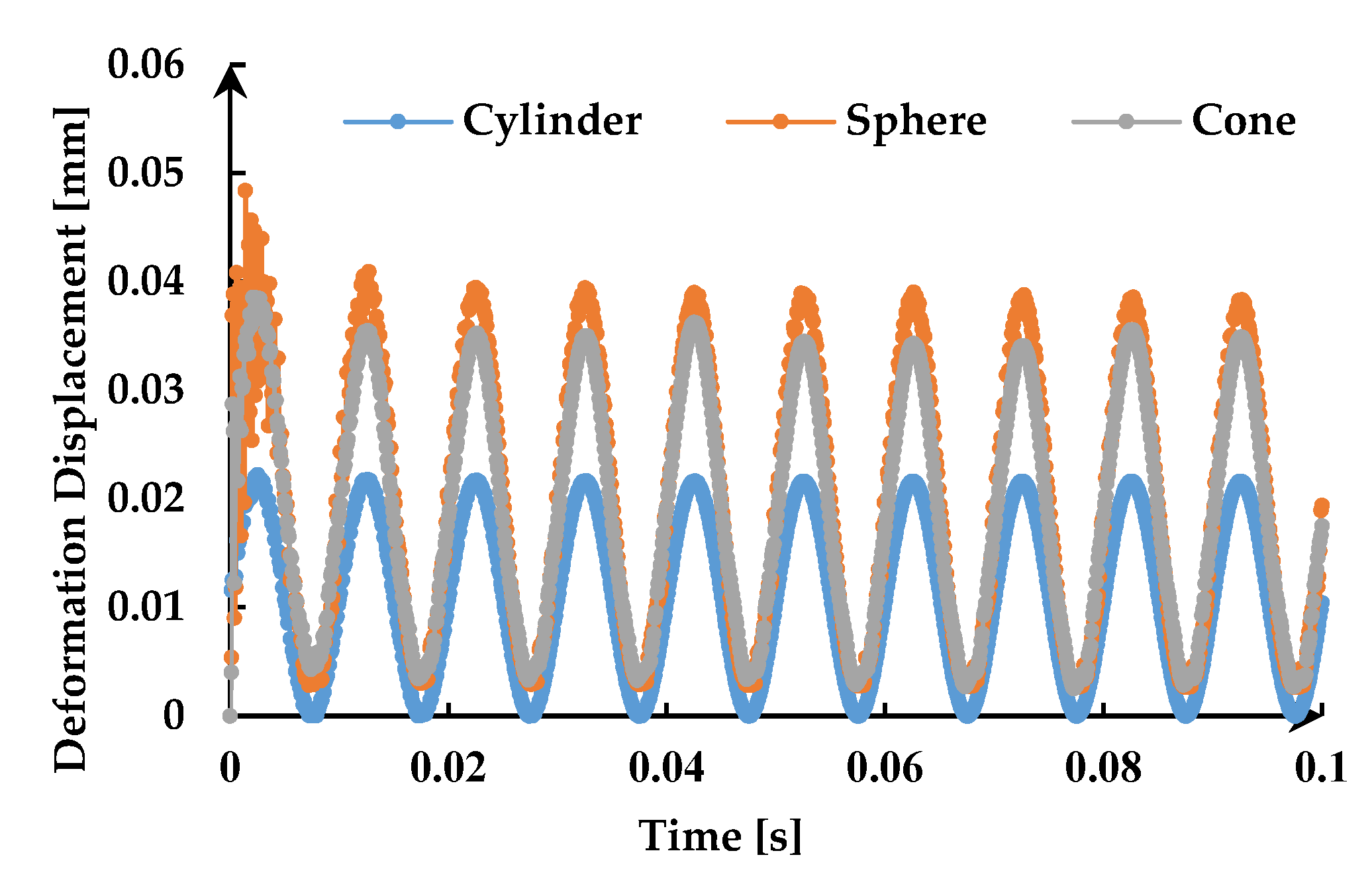
4.5. Influence of the Type of Indenter

In addition to the cylindrical indenter, the spherical and conical indenters are also common types of indenters. Therefore, in order to study the influence of the type of indenter on the deformation displacement and stress field of the rock under static-dynamic loads, the same numerical simulations are carried out by replacing the indenter in sequence. As shown in Figure 13, these three kinds of indenters have a diameter of 5 mm, and a reference point PR is set at the center of the upper surface of each indenter, which is also the position applied by static-dynamic loads. Besides, in order to satisfy the conditions for the convergence of the three models, the static load applied is 100 N and the harmonic dynamic load is 100 N, with a frequency of 100 Hz.
Firstly, in order to analyze the influence of the type of indenter on the deformation of the rock under static-dynamic loads, the deformation displacements of the rock in the horizontal and vertical directions are compared, as shown in Figure 14 and Figure 15.
Figure 14 shows the deformation at the same position on the rock surface for three indenters. It can be seen from Figure 14 that the amplitudes of deformation displacement of the rock for the spherical and conical indenters are close to each other, and are higher than that of the cylindrical indenter under the same static-dynamic loads. Figure 15a displays the selected path in the vertical direction of the rock, and the corresponding deformation displacement at t = 0.1 s is plotted in relation to the distance from the indenter in Figure 15b. As shown in the figure, all the deformation displacements of the rock for three indenters decrease with the increase of the distance from the rock surface. The deformation displacement of the rock for the spherical and conical indenter near the rock surface is obviously higher than that of the cylindrical indenter, but as the distance increases, the deformation magnitude of the rock for the three indenters tends to be the same. In summary, the deformation displacements of the rock under the static-dynamic loads for the spherical and conical indenters are similar, and the deformation degree of the rock is significantly greater than that of the cylindrical indenter.
Subsequently, the influence of the type of indenter on the stress field of the rock under static-dynamic loads is discussed. Figure 16 demonstrates the maximum and minimum stress counterplots for the three types of indenters under static-dynamic loads, respectively. Please note the color code for each experiment which present maximum and minimum stress for each figure. It can be seen from Figure 16a that the maximum stress of rock under the conical indenter is the largest, followed by the spherical indenter, and it is the smallest for cylindrical indenter. Similarly, the same conclusion can be drawn from the minimum stress of the rock in Figure 16b. This indicates that the average stress of the rock under the conical indenter is higher than that of the other two indenters under the same static-dynamic loads. However, from the point of view of the response range of the stress field, the one under the cylindrical indenter is the largest, while that under the conical indenter is the smallest, which is exactly contrary to the previous conclusion. The reason for the above results is mainly due to the difference in the contact area between the three types of indenters and the rock, which implies that a small contact area creates a large stress field but a small response range of the rock. Thus, the extreme value of stress and the response range of the rock should be considered comprehensively when the type of indenter is optimized for operation.

4.6. Discussion

In fact, although the static-dynamic loads have an additional harmonic dynamic load compared to the static load, the average force applied to the indenter is the same under two loading conditions, which means that no extra work is done on the indenter. This point can also be proven from the equilibrium position of the deformation displacement of the rock under static-dynamic loads, whose average value is also the same as that under static load. However, the beneficial effects of static-dynamic loads on rock fracture are obvious due to the existence of harmonic dynamic load. It can not only change the deformation shape of the rock making it easier to reach the failure level, but also cause the rock to vibrate periodically aggravating its fatigue damage, so that fatigue fracture may occur in the rock even if the fracture limit is not reached. In addition, the static-dynamic loads expand the response degree and range of the rock, which is also beneficial for rock fragmentation. As rock fragmentation is a critical component for many field operations, such as drilling and mining, the application of harmonic dynamic load will help improve the efficiency of these field operations. In other words, it is meaningful to study the response of the rock under static-dynamic loads. This paper only focuses on the deformation displacement and the stress field of the brittle rock which is the process before fracture. However, there are still many works, such as the effect of static-dynamic loads on the plastic deformation, fracture and crack propagation of the rock, which need to be done in the future.

5. Conclusions

This work has presented a detailed numerical study on the deformation displacement and the stress field of the brittle rock under static-dynamic loads. The 3D uniaxial compression simulation is firstly carried out to calibrate and determine the property parameters of the rock and the failure displacement in the simulation is obtained. Then, the 3D modeling of the cylindrical indenter intrusion the rock is proposed and mesh size sensitivity analysis is performed to ensure that the grid does not affect the results. At last, four main parameters are considered, namely the position on the rock, the frequency and the amplitude of dynamic load and the type of the indenter to discuss the effect of static-dynamic loads on the deformation displacement and stress field of the rock. Besides, the numerical results are compared between the static and static-dynamic loading conditions.
Based on the simulation undertaken, three main conclusions can be drawn as follows:
  • The deformation displacement of the rock presents a harmonic variation under static-dynamic loads and decreases as the distance from the center of the indenter increases. The frequency of dynamic load only changes the fluctuation period of the deformation displacement of the rock without changing its amplitude, while the amplitude of dynamic load has the opposite effect on it. Besides, the deformation displacement of the rock increase with the decrease of the contact area between the rock and the indenter.
  • The stress field of the rock also presents periodic changes due to the existence of harmonic dynamic load. The magnitude of the stress field of the rock increases with the increase of the amplitude of dynamic load and does not change with the change of the frequency of dynamic load. In addition, a small contact area between the rock and the indenter creates a large stress field but a small response range of the rock.
  • Compared with the deformation displacement and the stress field of the rock under the same static load, the deformation displacement of the rock is more likely to exceed its failure level and the maximum stress generated is also larger, and the response degree and range of the rock is wider under static-dynamic loads.
In addition, the static-dynamic loads can also aggravate the fatigue damage of the rock and allow less static load, which is more conducive to rock fracture. Therefore, it is meaningful to further study the mechanism of rock fragmentation under static-dynamic loads.

Author Contributions

X.L. and S.T. conducted the 3D uniaxial compression simulation; S.L. and W.L. performed the indenter intrusion simulation; M.K. and V.V. analyzed the simulation results; S.L. wrote the paper. All authors have read and agreed to the published version of the manuscript.

Funding

The support of National Natural Science Foundation of China (No. 51704074) and Youth Science Foundation of Heilongjiang Province (No. QC2018049) are gratefully acknowledged. The work is also supported by Talent Cultivation Foundation (No. SCXHB201703; No. ts26180119; No. td26180141) and Youth Science Foundation (No. 2019QNL-07) of Northeast Petroleum University.

Conflicts of Interest

The authors are aware of the ethical responsibilities and they declare that they have no conflict of interest.

List of Symbols

μPoisson’s ratio
EElastic modulus, Pa
aRadius of the indenter, m
rDistance from the center of the indenter, m
qStatic load per unit area, N/m2
q(t)Dynamic load per unit area, N/m2

References

  1. Jia, B.; Tsau, J.S.; Barati, R. A review of the current progress of CO2 injection EOR and carbon storage in shale oil reservoirs. Fuel 2019, 236, 404–427. [Google Scholar] [CrossRef]
  2. Aguiar, R.R.; Weber, H.I. Mathematical modeling and experimental investigation of an embedded vibro-impact system. Nonlinear Dyn. 2011, 65, 317–334. [Google Scholar] [CrossRef]
  3. Pavlovskaia, E.; Hendry, D.C.; Wiercigroch, M. Modelling of high frequency vibro-impact drilling. Int. J. Mech. Sci. 2015, 91, 110–119. [Google Scholar] [CrossRef] [Green Version]
  4. Wiercigroch, M.; Vaziri, V.; Kapitaniak, M. RED: Revolutionary Drilling Technology for Hard Rock Formations. In Proceedings of the 2017 SPE/IADC Drilling Conference, The Hague, The Netherlands, 14–16 March 2017; pp. 1234–1241. [Google Scholar]
  5. Potthast, C.; Twiefel, J.; Wallaschek, J. Modelling approaches for an ultrasonic percussion drill. J. Sound Vib. 2007, 308, 405–417. [Google Scholar] [CrossRef]
  6. Bai, D.; Quan, Q.; Wang, Y.; Tang, D.; Deng, Z. A longitudinal & longitudinal-torsional vibration actuator for rotary-percussive ultrasonic planetary drills. Adv. Space Res. 2019, 63, 1065–1072. [Google Scholar]
  7. Li, S.Q.; Yan, T.; Li, W.; Bi, F.Q. Modeling of vibration response of rock by harmonic impact. J. Nat. Gas Sci. Eng. 2015, 23, 90–96. [Google Scholar] [CrossRef]
  8. Dong, G.; Chen, P. 3D numerical simulation and experiment validation of dynamic damage characteristics of anisotropic shale for percussive-rotary drilling with a full-scale PDC bit. Energies 2018, 11, 1326. [Google Scholar] [CrossRef] [Green Version]
  9. Bilgin, N.; Copur, H.; Balci, C. Effect of replacing disc cutters with chisel tools on performance of a TBM in difficult ground conditions. Tunn. Undergr. Space Technol. 2012, 27, 41–51. [Google Scholar] [CrossRef]
  10. Bejari, H.; Hamidi, J.K. Simultaneous effects of joint spacing and orientation on TBM cutting efciency in jointed rock masses. Rock Mech. Rock Eng. 2013, 46, 897–907. [Google Scholar] [CrossRef]
  11. Souissi, S.; Hamdi, E.; Sellami, H. Microstructure effect on hard rock damage and fracture during indentation process. Geotech. Geol. Eng. 2015, 33, 1539–1550. [Google Scholar] [CrossRef]
  12. Zhao, X.B.; Yao, X.H.; Gong, Q.M.; Ma, H.S.; Li, X.Z. Comparison study on rock crack pattern under a single normal and inclined disc cutter by linear cutting experiments. Tunn. Undergr. Space Technol. 2015, 50, 479–489. [Google Scholar] [CrossRef]
  13. Alehossein, H.; Detournay, E.; Huang, H. An analytical model for the indentation of rocks by blunt tools. Rock Mech. Rock Eng. 2000, 33, 267–284. [Google Scholar] [CrossRef]
  14. Momber, A.W. Deformation and fracture of rocks loaded with spherical indenters. Int. J. Fract. 2004, 125, 263–279. [Google Scholar] [CrossRef]
  15. Zhang, H.; Huang, G.; Song, H.; Kang, Y. Experimental investigation of deformation and failure mechanisms in rock under indentation by digital image correlation. Eng. Fract. Mech. 2012, 96, 667–675. [Google Scholar] [CrossRef]
  16. Huang, H.; Detournay, E. Discrete element modeling of tool-rock interaction II: Rock indentation. Int. J. Numer. Anal. Met. 2013, 37, 1930–1947. [Google Scholar] [CrossRef]
  17. Liu, T.; Lin, B.; Yang, W.; Zou, Q.; Kong, J.; Yan, F. Cracking process and stress field evolution in specimen containing combined flaw under uniaxial compression. Rock Mech. Rock Eng. 2016, 49, 3095–3113. [Google Scholar] [CrossRef]
  18. Wang, X.; Wen, Z.J.; Jiang, Y.J. Time–space effect of stress field and damage evolution law of compressed coal-rock. Geotech. Geol. Eng. 2016, 34, 1933–1940. [Google Scholar] [CrossRef]
  19. Ma, L.F.; Yari, N.; Wiercigroch, M. Shear stress triggering brittle shear fracturing of rock-like materials. Int. J. Mech. Sci. 2018, 146, 295–302. [Google Scholar] [CrossRef]
  20. Hogan, J.D.; Boonsue, S.; Spray, J.G.; Rogers, R.J. Micro-scale deformation of gypsum during micro-indentation loading. Int. J. Rock Mech. Min. 2012, 54, 140–149. [Google Scholar] [CrossRef]
  21. Ajibose, O.K.; Wiercigroch, M.; Akisanya, A.R. Experimental studies of the resultant contact forces in drill bit–rock interaction. Int. J. Mech. Sci. 2015, 91, 3–11. [Google Scholar] [CrossRef] [Green Version]
  22. Kitamura, M.; Hirose, T. Strength determination of rocks by using indentation tests with a spherical indenter. J. Struct. Geol. 2017, 98, 1–11. [Google Scholar] [CrossRef]
  23. Shariati, H.; Saadati, M.; Bouterf, A.; Weddfelt, K.; Larsson, P.L.; Hild, F. On the inelastic mechanical behavior of granite: Study based on quasi-oedometric and indentation tests. Rock Mech. Rock Eng. 2019, 52, 645–657. [Google Scholar] [CrossRef] [Green Version]
  24. Yoffe, E.H. Elastic stress fields caused by indenting brittle materials. Philos. Mag. A 1982, 46, 617–628. [Google Scholar] [CrossRef]
  25. Feng, G.; Qu, S.; Huang, Y.; Nix, W.D. An analytical expression for the stress field around an elastoplastic indentation/contact. Acta Mater. 2007, 55, 2929–2938. [Google Scholar] [CrossRef]
  26. Weddfelt, K.; Saadati, M.; Larsson, P.L. On the load capacity and fracture mechanism of hard rocks at indentation loading. Int. J. Rock Mech. Min. 2017, 100, 170–176. [Google Scholar] [CrossRef]
  27. Zhu, X.; Liu, W.; He, X. The investigation of rock indentation simulation based on discrete element method. KSCE J. Civ. Eng. 2017, 21, 1201–1212. [Google Scholar] [CrossRef]
  28. Liu, H.Y.; Kou, S.Q.; Lindqvist, P.A.; Tang, C.A. Numerical simulation of the rock fragmentation process induced by indenters. Int. J. Rock Mech. Min. 2002, 39, 491–505. [Google Scholar] [CrossRef]
  29. Li, X.; Wang, S.; Ge, S. Numerical simulation of rock fragmentation during cutting by conical picks under confining pressure. Compt. Rendus Mec. 2017, 345, 890–902. [Google Scholar] [CrossRef]
  30. Yari, N.; Kapitaniak, M.; Vaziri, V.; Ma, L.F.; Wiercigroch, M. Calibrated FEM Modelling of Rock Cutting with PDC Cutter. MATEC Web Conf. 2018, 148, 16006. [Google Scholar] [CrossRef] [Green Version]
  31. Li, H.S.; Liu, S.Y.; Xu, P.P. Numerical simulation on interaction stress analysis of rock with conical picks. Tunn. Undergr. Space Tech. 2019, 85, 231–242. [Google Scholar] [CrossRef]
  32. Liu, W.; Qian, X.; Li, T.; Zhou, Y.; Zhu, X. Investigation of the tool-rock interaction using Drucker-Prager failure criterion. J. Petrol. Sci. Eng. 2019, 173, 269–278. [Google Scholar] [CrossRef]
  33. Zhang, H.; Song, H.; Kang, Y.; Huang, G.; Qu, C. Experimental analysis on deformation evolution and crack propagation of rock under cyclic indentation. Rock Mech. Rock Eng. 2013, 46, 1053–1059. [Google Scholar] [CrossRef]
  34. Li, X.; Wang, S.; Wang, S. Experimental investigation of the influence of confining stress on hard rock fragmentation using a conical pick. Rock Mech. Rock Eng. 2018, 51, 255–277. [Google Scholar] [CrossRef]
  35. Wang, S.; Li, X.; Du, K.; Wang, S. Experimental investigation of hard rock fragmentation using a conical pick on true triaxial test apparatus. Tunn. Undergr. Space Tech. 2018, 79, 210–223. [Google Scholar] [CrossRef]
  36. Fang, K.; Zhao, T.; Zhang, Y.; Qiu, Y.; Zhou, J. Rock cone penetration test under lateral confining pressure. Int. J. Rock Mech. Min. 2019, 119, 149–155. [Google Scholar] [CrossRef]
  37. Shan, R.; Jiang, Y.; Li, B. Obtaining dynamic complete stress-strain curves for rock using the Split Hopkinson Pressure Bar technique. Int. J. Rock Mech. Min. 2000, 37, 983–992. [Google Scholar] [CrossRef]
  38. Saksala, T. Damage-viscoplastic consistency model with a parabolic cap for rocks with brittle and ductile behavior under low-velocity impact loading. Int. J. Numer. Anal. Meth. Geomech. 2010, 34, 1362–1386. [Google Scholar] [CrossRef]
  39. Wang, S.Y.; Sloan, W.; Liu, H.Y.; Tang, C.A. Numerical simulation of the rock fragmentation process induced by two drill bits subjected to static and dynamic (impact) loading. Rock Mech. Rock Eng. 2011, 44, 317–332. [Google Scholar] [CrossRef]
  40. Duan, K.; Kwo, C.Y.; Tham, L.G. Micromechanical analysis of the failure process of brittle rock. Int. J. Numer. Anal. Met. 2015, 39, 618–634. [Google Scholar] [CrossRef]
  41. Chen, G.; Li, T.; Guo, F.; Wang, Y. Brittle mechanical characteristics of hard rock exposed to moisture. Bull. Eng. Geol. Environ. 2017, 76, 219–230. [Google Scholar] [CrossRef]
  42. Liu, G.; Cai, M.; Huang, M. Mechanical properties of brittle rock governed by micro-geometric heterogeneity. Comput. Geotech. 2018, 104, 358–372. [Google Scholar] [CrossRef]
Figure 1. The 3D modeling of uniaxial compression test of sandstone: (a) The finite element (FE) model consists of a cylinder and two thin disks. The highlighted arrow represents that the upper disk is subjected to a downward displacement load of 5 mm. (b) Contour plot of uniaxial compression damage of sandstone.
Energies 13 00851 g001
Figure 2. Stress–strain curves of sandstone obtained from experiment and numerical simulation.
Energies 13 00851 g002
Figure 3. The 3D finite element model: (a) The whole model. (b) A quarter of the model.
Energies 13 00851 g003
Figure 4. Deformation displacements from the FE model for different element numbers.
Energies 13 00851 g004
Figure 5. Meshing elements of the rock: (a) Part view. (b) Top view.
Energies 13 00851 g005
Figure 6. Numerical results showing deformation displacements of different positions on the surface of the rock for cylindrical indenter: (a) Top view of the rock surface. (b) The relationships of deformation displacement versus time of points A, B, C and D.
Energies 13 00851 g006
Figure 7. Numerical results showing deformation displacement versus time relationships of the rock for cylindrical indenter under two kinds of loading conditions.
Energies 13 00851 g007
Figure 8. The comparison of 3D Mises stress contour plots under static and static-dynamic loads for cylindrical indenter during an impact period.
Energies 13 00851 g008
Figure 9. Numerical results showing deformation displacement versus time relationships of the rock for cylindrical indenter under static-dynamic loads with different frequencies of dynamic load.
Energies 13 00851 g009
Figure 10. The comparison of Mises stress contour plots under static and static-dynamic loads with different frequencies of dynamic load for cylindrical indenter: (a) MaxMises. (b) MinMises.
Energies 13 00851 g010
Figure 11. Numerical results showing deformation displacement versus time relationships of the rock for cylindrical indenter under static-dynamic loads with different amplitudes of dynamic load.
Energies 13 00851 g011
Figure 12. The comparison of Mises stress contour plots under static and static-dynamic loads with different amplitudes of dynamic load for cylindrical indenter: (a) MaxMises. (b) MinMises.
Energies 13 00851 g012
Figure 13. 3D finite element models of indenters: (a) cylinder; (b) sphere; (c) cone. RP, Fs and Fd represent the reference point, static and dynamic load, respectively.
Energies 13 00851 g013
Figure 14. Deformation displacement versus time relationships of the rock for three types of indenters under static-dynamic loads.
Energies 13 00851 g014
Figure 15. Comparison of deformation displacement of three types of indenters under static-dynamic loads: (a) The selected path in the vertical direction of the rock. (b) Deformation displacement versus distance from the rock surface.
Energies 13 00851 g015
Figure 16. Comparison of the stress field for three types of indenters under static-dynamic loads: (a) Maximum Mises. (b) Minimum Mises. As there are large differences between the maximum and minimum stress for the three types of indenters, the uniform legend is not applicable here. Please note the color code for each experiment which present maximum and minimum stress for each figure.
Energies 13 00851 g016
Table 1. Property parameters of sandstone in the simulation.
MaterialParameterValueParameterValue
SandstoneDensity (t/mm3)2.7 × 10−9Angle of Friction (°)50
Elastic Modulus (MPa)7228Dilation Angle (°)8
Poisson’s Ratio0.3Flow Stress Ratio0.8
Failure Displacement (mm)0.02Yield Stress (MPa)67
Fracture Strain5 × 104
Table 2. Property parameters of the rock and the indenter in the simulation.
MaterialParameterValueParameterValue
SandstoneDensity (t/mm3)2.7 × 10−9Elastic Modulus (MPa)7228
Poisson’s Ratio0.3
IndenterDensity (t/mm3)7.85 × 10−9Elastic Modulus (MPa)2.06 × 10⁵
Poisson’s Ratio0.3

