Article

Solvent-Dictated Sodium Sulfur Redox Reactions: Investigation of Carbonate and Ether Electrolytes

1
Xi’an Institute of Flexible Electronics (IFE), Northwestern Polytechnical University (NPU), 127 West Youyi Road, Xi’an 710072, Shaanxi, China
2
Helmholtz Institute Ulm, Helmholtzstraße 11, 89081 Ulm, Germany
3
Karlsruhe Institute of Technology (KIT), D-76021 Karlsruhe, Germany
4
Institute of Surface Chemistry and Catalysis, Ulm University, Albert-Einstein-Allee 47, D-89081 Ulm, Germany
*
Author to whom correspondence should be addressed.
Energies 2020, 13(4), 836; https://doi.org/10.3390/en13040836
Submission received: 9 January 2020 / Revised: 3 February 2020 / Accepted: 12 February 2020 / Published: 14 February 2020
(This article belongs to the Special Issue Novel Technologies for Metal-Ion and Metal Batteries)

Abstract

:
Sulfur-based cathode chemistries are essential for the development of high energy density alkali-ion batteries. Here, we elucidate the redox kinetics of sulfur confined on carbon nanotubes, comparing its performance in ether-based and carbonate-based electrolytes at room temperature. The solvent is found to play a key role for the electrochemical reactivity of the sulfur cathode in sodium–sulfur (Na–S) batteries. Ether-based electrolytes contribute to a more complete reduction of sulfur and enable a higher electrochemical reversibility. On the other hand, an irreversible solution-phase reaction is observed in carbonate solvents. This study clearly reveals the solvent-dependent Na–S reaction pathways in room temperature Na–S batteries and provides an insight into realizing their high energy potential, via electrolyte formulation design.

Graphical Abstract

1. Introduction

The identification of efficient and effective but low-cost energy storage technologies is still a challenge, preventing the full integration of renewable energy sources into the grid at present. Rechargeable batteries represent one of the best promises for such a target, at least for a number of applications. Here, electrical energy can be efficiently stored and released according to demand, and their compact size makes them highly suitable for use at small grid-scale. Among the most promising electrode materials for such applications is certainly sulfur, which can potentially enable lithium metal anode batteries with about five times higher specific energy compared to current lithium–ion batteries, while being rather inexpensive [1]. Nonetheless, there is still concern with the foreseen resource and supply risks of lithium [2].
Therefore, sodium–sulfur (Na–S) batteries appear to be an ideal candidate due to the rather low economic and geopolitical impact of their raw materials [3,4]. The theoretical capacity of a Na–S battery is ~1672 mAh g−1, based on the sulfur with final product of Na2S. Despite the success of high-temperature Na–S batteries (>300 °C) for grid-scale application, the problems associated with the solid electrolyte and/or cell sealing integrity failures, resulting in the risk of molten sodium explosive reactions, motivate the exploration for alternatives. A decrease in operation temperature could, in fact, offer the opportunity to improve the durability and safety of the Na–S battery [5]. Thus, the development of room temperature (RT) Na–S batteries with conventional, organic solvent-based electrolytes is triggering tremendous research interest [6]. In fact, considering their expected low cost, RT Na–S batteries may be the solution for the future of stationary and large-scale energy storage, enabling efficient and effective use of sustainable energy sources [6,7]. So far, most of the work has focused on the exploration of polymer electrolytes, either gel-polymer or solid-polymer, to suppress the polysulfides’ shuttle pathway [8,9,10,11,12]. Moreover, attempts to fabricate sodium polysulfides’ electrodes with carbonaceous interlayers and functional separators have been demonstrated to enhance the cycling stability of Na–S batteries [13,14,15]. However, RT Na–S batteries are still suffering from low reversible capacity and poor cycling stability. The low reversible capacity is mainly ascribed to the low electric conductivity of bulk sulfur and the sluggish reaction kinetics between sulfur and sodium, resulting in the poor utilization of the sulfur cathode [9]. In addition, the high self-discharge rate and rapid capacity fading due to sodium polysulfides’ formation and shuttling across the electrolyte appear almost inevitable for RT Na–S batteries. Recently, intensive efforts have been made to identify and prepare highly efficient S-host substrates from functional carbons and inorganic metal oxides (sulfide), improving the utilization of the sulfur active material [16,17,18,19,20,21,22,23].
Although the understanding of the sulfur reduction reactions in conventional organic electrolytes is a precondition for the realization of high performance RT Na–S batteries, only very few studies have directly been devoted to unfold the sulfur conversion reaction and intermediates under battery conditions, in these carbon frameworks. A few studies have demonstrated the pronounced effects of the organic electrolytes’ solvation properties on the lithium–sulfur (Li–S) redox reactions [24,25,26,27]. Thus, understanding the solvent–dependent Na–S redox processes, i.e., how the solvent affects the Na–S redox reactions, may provide significant insight, allowing the design of improved electrolytes for high performance Na–S batteries.
In this work, we systematically investigate the electrolyte solvent on the sulfur redox reaction pathway in RT Na-S batteries, comparing its performance in ether- and carbonate-based electrolytes. The use of tetraethyleneglycol-dimethyl-ether (TEGDME) ether-based electrolyte contributes to a more complete reduction of sulfur and enables a higher electrochemical reversibility. On the other hand, an irreversible solution phase reaction is observed in carbonate solvents. Both in situ X-ray diffraction (XRD) and ex situ X-ray photoelectron spectroscopy (XPS) measurements were performed to reveal the sulfur redox reaction process. This study presents a basic understanding on the solvent-dependent sulfur redox reactions, providing a solid basis for the systematic development of room temperature Na–S batteries.

2. Results and Discussion

In order to address the major problem originating from the insulating nature of sulfur, the sulfur/carbon nanotube (S/CNT) composite was synthesized by a simple melt-diffusion method, which is briefly described in the Experimental section [28]. Results on the characterization of the as-prepared S/CNT composite are presented in Figure S1 (see Supporting Information). The scanning electron microscopy (SEM) images, revealing the morphology of the S/CNT composite, show no obvious aggregation of the sulfur particles, which indicates a homogenous distribution of the active sulfur in the carbon host. The XRD pattern confirms the orthorhombic crystal structure of cyclo-S8 (PDF#74-1465). The broad diffraction peak located at 25° can be attributed to the graphitic CNT. The TG curve shows a single-stage sulfur loss, by evaporation between 200 and 300 °C. Quantitative evaluation yields a sulfur content of about 69 wt.%. Initially, the S/CNT electrode was investigated in the Li–S battery to confirm its activity. As shown in Figure S2 (panels a and b), the composite shows a specific discharge capacity of 1020 mAh g−1 (based on sulfur) at 100 mA g−1 and maintained 490 mAh g−1 at 1675 mA g−1, without any capacity fading over 75 cycles.
The solvent-dependent redox kinetics and the reaction behavior of the RT Na–S cells were further investigated in two different electrolytes, namely, 1.5 M NaClO4 in TEGDME with 0.2 M NaNO3 and 1.0 M NaClO4 in propylene carbonate/ethylene carbonate (PC/EC, 1:1 v/v) with 5 wt.% fluoroethylene carbonate (FEC), which are commonly used for Na–S batteries. The CV scans of S/CNT electrodes in these electrolytes are shown in Figure 1. The test of the cell employing the TEGDME-based electrolyte (panel a) shows three cathodic peaks at 2.2, 1.6, and 1.0 V, supporting for a three-step reduction of sulfur in the presence of Na ions. Two broad anodic peaks centered at 2.0 and 2.4 V indicate, however, that the oxidation occurs in two steps. In contrast, for the cell employing the PC/EC-based electrolyte, we only find a single clear reduction peak at 2.1 V (panel b), followed by two other features barely distinguishable at lower potentials. No peaks are detected during the anodic scan. Such a complete irreversibility may result from a rapid nucleophilic attack of reduced sulfur species on the carbonate solvents, as it was reported for the analogous lithium system [
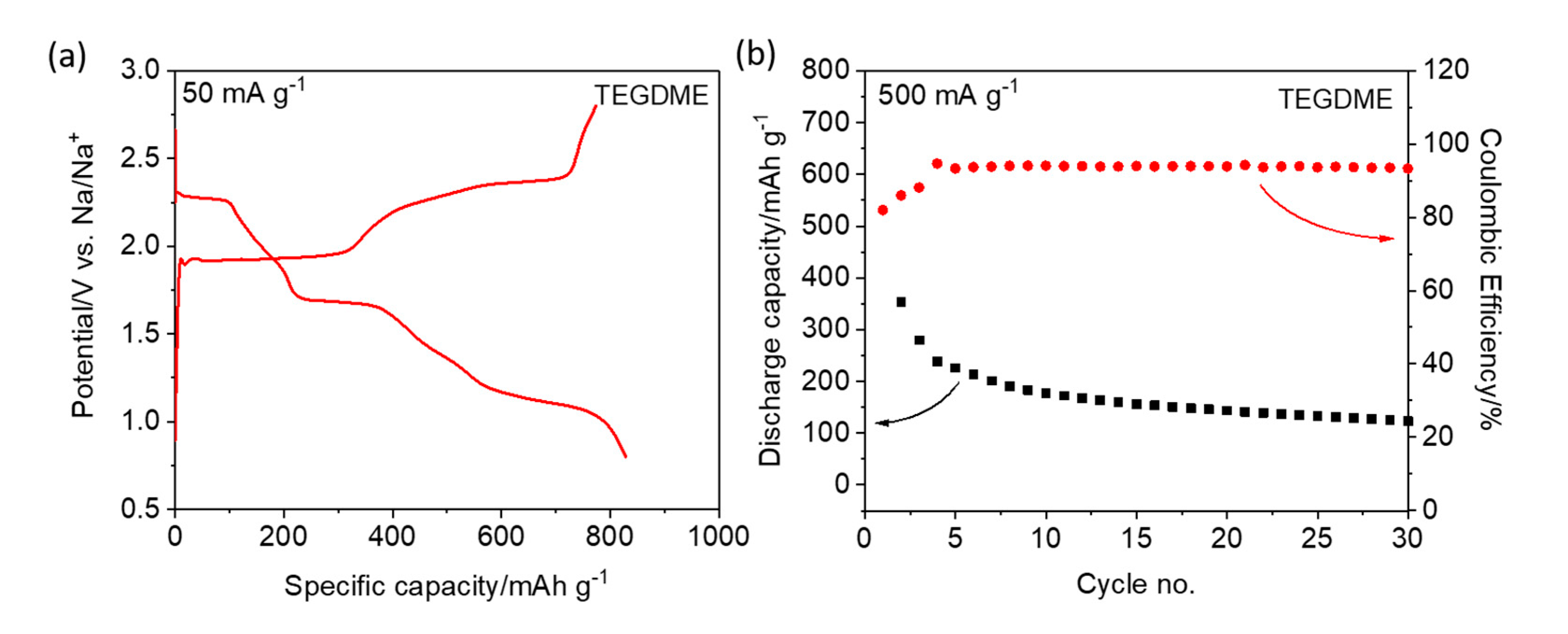
24]. The first galvanostatic charge/discharge profiles of the S/CNT electrode at 50 mA g−1 are presented in Figure 2a and Figure S3 (see Supporting Information). Three distinct voltage plateaus are observed at 2.3, 1.7, and 1.1 V during the discharge of the TEGDME-based cell, which is consistent with the CV results. The electrode shows an initial specific discharge capacity of 828 mAh g−1 and a specific charge capacity of 774 mAh g−1, resulting in an initial Coulombic efficiency of 93.5%. The high coulombic efficiency is attributed to the presence of NaNO3, which is proposed to reduce/suppress self-discharge. However, at higher specific currents (e.g., 500 mA g−1), both the Coulombic efficiency and the reversible capacity are rather poor (c.f., Figure S4). Compared with the Li–S chemistry (c.f., Figure S2a,b), the Na–S cells exhibit a different voltage (kinetics) and long-term cycling behavior. In fact, a rapid capacity fade occurs, which may be due to the dissolution of sodium polysulfides and their migration through the electrolyte (see Figure 2b). Using the PC/EC-based electrolyte, the S/CNT electrode shows a lower specific discharge capacity (i.e., 420 mAh g−1, corresponding to an average reduction state of S42−) and negligible charge capacity (see Figure S3 in Supporting Information). Such an extremely poor reversibility makes the carbonate-based electrolyte unsuitable for Na/S batteries, at least under these conditions.
Electrochemical impedance spectroscopy (EIS) was applied on the assembled cells after resting (3 h) at the open circuit voltage (OCV) to obtain information on the self-discharge behavior. The impedance spectra exhibit two distorted semicircles in the high and medium frequency regions, followed by a steep increase in the low frequency regions. These represent the resistance of the passivation layer, the charge transfer resistance and the solid-state diffusion, respectively [29]. The intercept with the x axis at high frequency is attributed to the electrolyte resistance. The passivation layer resistance is associated with the unstable solid-electrolyte interphase (SEI), caused by the shuttle effect in the cathode and sodium dendrites on the anode. Nyquist plots recorded using the ether and carbonate electrolytes, respectively, are presented in Figure 3. As seen in Figure 3a, the cell using a TEGDME electrolyte has a higher film resistance than that employing carbonate. This results from the dissolution of polysulfides and the side reaction of the sodium metal electrode with the electrolyte, leading to a thicker passivation layer in the ether-based electrolyte than in the carbonate electrolyte [30,31]. The cell employing the TEGDMA electrolyte shows much higher electrolyte and SEI resistances, resulting from polysulfide dissolution. This indicates a clear role of dissolved sodium polysulfides in the formation of the passivation layer. Overall, the TEGDME-based Na–S cell shows a much smaller charge transfer resistance than the carbonate-based cell, indicating faster redox kinetics in the former case.
The sodiation overpotentials and kinetics of the S/CNT electrodes in the two electrolytes were evaluated by galvanostatic intermittent titration techniques (GITT), using specific current pulses of 50 mA g−1 per one hour, each followed by a rest period of 6 h. The resulting voltage profiles are shown in Figure 3c,d [27]. The overall voltage profiles of the two cells during sodiation resemble those obtained during the galvanostatic discharge (c.f., Figure 2a and Figure S3). The overpotential of the S/CNT electrode in the PC/EC-based electrolyte increases sharply with the state of discharge (SoD), reflecting the decreasing kinetics. In contrast, the electrode tested in the TEGDME-based electrolyte shows a moderate overpotential at the beginning of the sodiation, indicating that the electrode kinetics for the conversion of S8 to long-chain polysulfides are rather fast. However, an increased polarization can be observed in the low voltage range. This phenomenon can be explained by the slow reaction kinetics for the conversion of the long-chain polysulfides into short-chain polysulfides, which is generally considered as a two-phase liquid-solid reaction. At the end, we find a small decrease on the overpotential, possibly due to the slight decrease of mass transport resistance at the end of the conversion reaction [32]. The different overpotentials for the sodiation process, which are mainly caused by the activation overpotentials, clearly indicate different activation energies for the RT Na–S reaction in carbonate and in ether-based electrolytes. It should be noted that the discharge capacity in the GITT measurement is higher than that obtained during continuous galvanostatic discharge, indicating that the milder GITT conditions (low pulse current and long rest periods) promote the utilization of sulfur and/or polysulfides in the carbon host, which has also been noted in Li–O2 batteries [33].
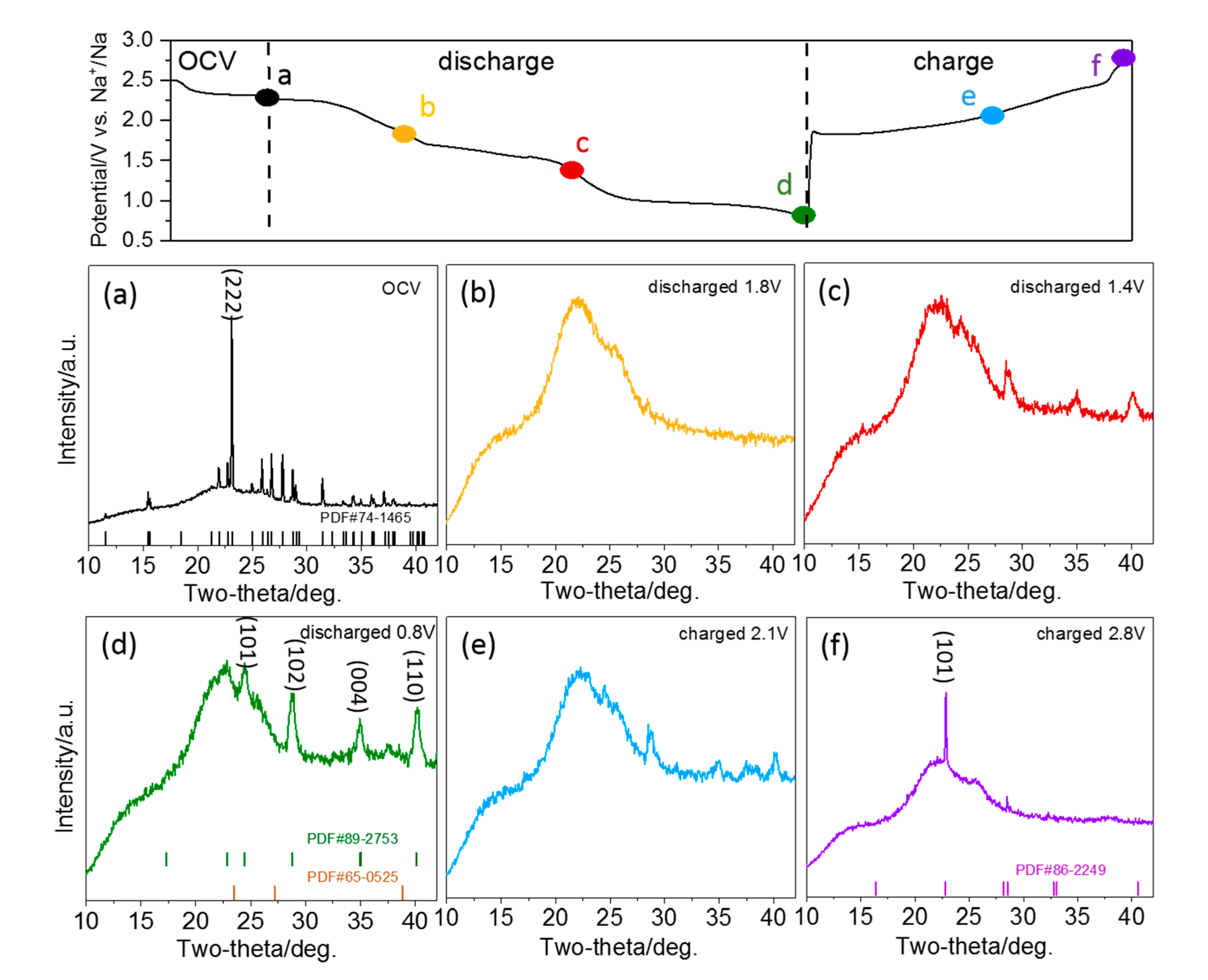
To understand the intermediates and products of the S/CNT cathode at different sodiation states, we performed an in situ X-ray diffraction (XRD) analysis [34]. The XRD patterns of a S/CNT electrode in TEGDME collected during the first discharge-charge cycle are shown in the contour map (2θ range of 10–42°) in Figure 4. To illustrate the phase changes more clearly, XRD diffractograms obtained at selected stages of sodiation (1.8 V, 1.4 V and 0.8 V) and desodiation (2.1 V and 2.8 V) are presented in Figure 5 additionally. The diffractograms recorded in the course of the first discharge can be subdivided into three regions, which are consistent with the charge-discharge curves (c.f., Figure 4, left panel). The first region starts at the beginning of sodiation and ends with the first plateaus region in the charge-discharge curve at ~1.7 V. At the end of this region (see also diffractogram at 1.8 V in Figure 5b), the features of S8 have disappeared completely. Instead, a broad peak located at 21.5° appears, which can be attributed to the presence of soluble long-chain polysulfides. Hence, all elemental sulfur is transformed to soluble long-chain polysulfides in this region. Further reduction of the polysulfides occurs in the second region, and at the end of it, the (101), (102), (004) and (110) signals of crystalline Na2S2 (PDF#89-2753) appear in the diffractogram recorded at 1.4 V (c.f., Figure 5c). In the final region, the reduction of polysulfides to Na2S2 proceeds, until the features of crystalline Na2S2 reach the highest intensity at the end of the discharge process at 0.8 V (c.f., Figure 5d). Upon charging, the intensity of the features related to crystalline Na2S2 decrease again, indicating the gradual re-oxidation to polysulfides. After recharging to 2.1 V (c.f., Figure 5e), the peaks of Na2S2 are weakened, but are still detectable. Close to the end of the charging process (at 2.8 V in Figure 5f), the Na2S2 peaks disappear, while new diffraction peaks appear at 22.8° and 28.5°, which correspond to the (101) and (300) features of cyclo-S6 (PDF#86-2249). They possibly indicate a direct oxidation from S62- to elemental S6.
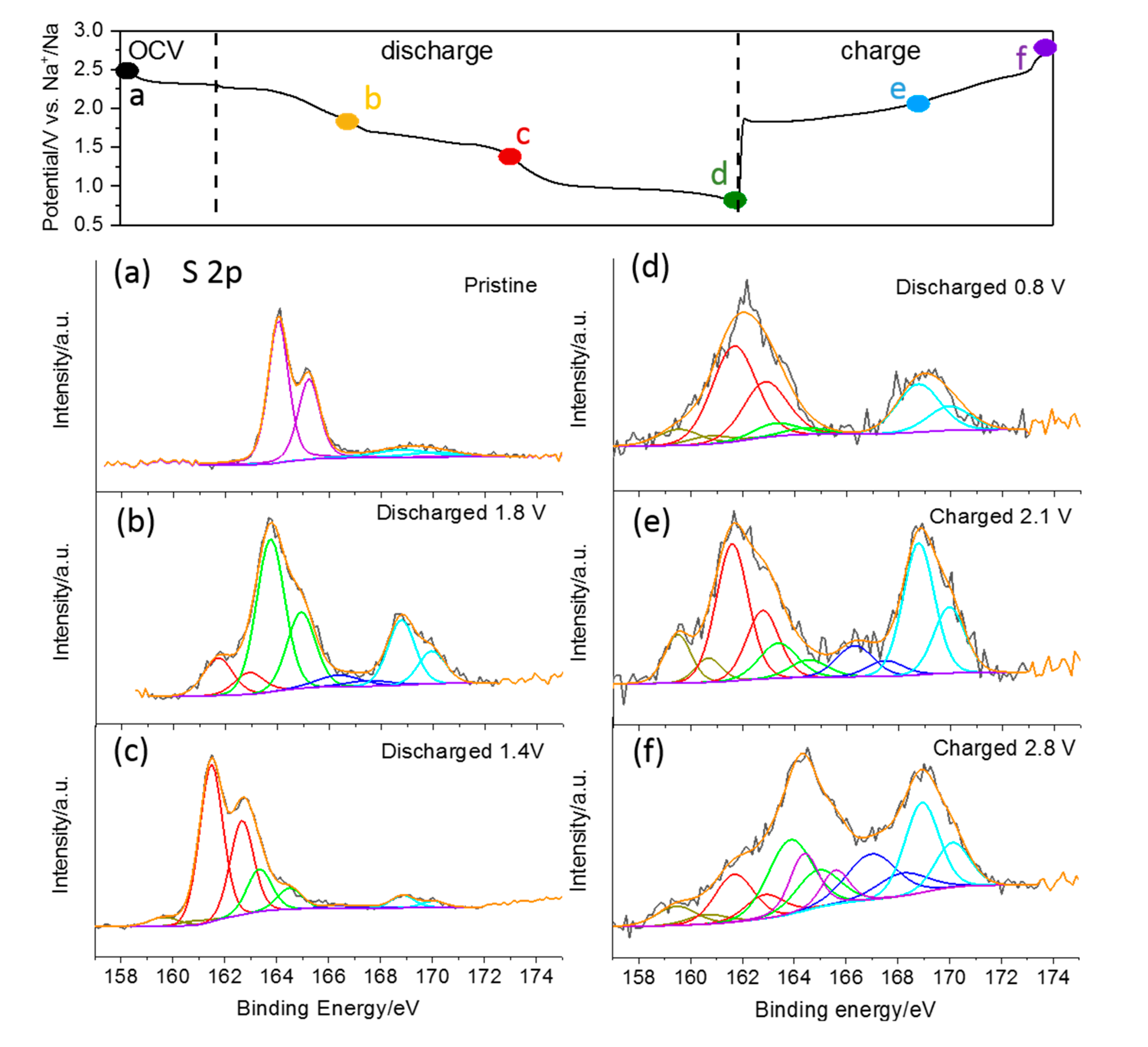
To reveal the changes of the chemical state of sulfur in the S/CNT electrode upon discharge and charge in TEGDME, ex situ XPS analysis was performed on the cycled electrodes at various discharge and charge states. Representative spectra in the S 2p range are shown in Figure 6. The spectrum of the pristine electrode exhibits a spin–orbit doublet centered at 164.0 and 165.2 eV, which is in good agreement with the binding energy reported for the S 2p1/2 and 2p3/2 peaks of S8 molecules [35]. It may be noted that peaks at higher binding energy (beyond 166 eV) are observed in this and all following spectra originating from oxidized species. The next XPS measurement was performed on an electrode sodiated to the end of the first discharge plateau at 1.8 V (c.f., charge-discharge curve in Figure 6). Here the main peak doublet is detected at 163.7/164.9 eV, i.e., 0.3 eV lower than in the first spectrum. It most probably contains contributions from bridging S atoms (SB0) in polysulfide species (Sx2−) and from elemental sulfur. Additionally, another peak doublet with lower intensity appears at a lower binding energy (161.6/162.8 eV), which we assign to the terminal S atoms (ST−1) of polysulfides. The intensity ratio of the two features is 4:1 in this measurement, showing just a minor excess of the expected value of SB to ST atoms in the initially formed long-chain polysulfide S82− (of 3:1). Hence, assuming again the stepwise reaction from S8 to S82− and then to smaller polysulfides (S62− etc.), this result suggests that most of the sulfur was transformed to S82− species at this point. The following XPS spectrum was recorded at the end of the second discharge plateau at 1.4 V (c.f., Figure 6c). It exhibits two peaks’ doublets at 163.3/164.5 and at 161.6/162.8 eV. The further peak shift of the first feature to lower binding energy indicates that the transformation of elemental sulfur to polysulfides is completed at this point. This is also corroborated by the intensity ratio of the two features, which shows a predominance of the peak doublet due to the terminal S atoms (ST−1) of polysulfides (by 0.3:1), i.e., small polysulfide species like S22− and S42− are present at this point. Considering that solid crystalline Na2S4 has not been detected in XRD measurements at this stage of sodiation, it is plausible to assume that the formation of Na2S4 takes place as a liquid to liquid reaction step in the TEGDME-based electrolyte. The XPS spectrum recorded after discharging to 1.4 V shows another small feature at even lower binding energy (159.5/160.7 eV), which can be assigned to S2−. It is interesting to note that the in situ XRD measurements do not show the presence of the solid product Na2S (PDF#65-0525) at any stage of electrochemical sodiation. At the end of discharge (at 0.8 V, c.f., Figure 6d), the S2p spectrum is dominated by the peak doublet related to terminal S atoms (ST−1), while the feature of bridging S atoms (SB0) has almost disappeared. Furthermore, the peak doublet of S2− is detected again with small intensity. From this result we conclude that the main product upon complete discharge is Na2S2, with a theoretical specific capacity of 836 mAh g−1, which agrees with previous studies of the Na–S chemistry [36,37]. Upon recharging, the signal of bridging S atoms (SB0) reappears (after charging to 2.1 V) and eventually dominates the spectrum again (after charging to 2.8 V). At the same time, its peak position shifts back to higher binding energy (to 163.8/165.0 eV after charging to 2.8 V), indicating that elemental S also contributes to this feature at the end of recharge. Surprisingly, the peak doublet due to Na2S persisted in the spectra of the recharged samples, i.e., the reaction from Na2S back to higher sulfides seems to be kinetically hindered, and it may be assumed that this reaction occurs only in microporous carbon with a small pore size [18].
To probe the reaction mechanism of sodiation of the S/CNT electrodes in the carbonate (PC/EC) based electrolyte, we collected similar in situ XRD diffractograms and ex situ XPS spectra. Since charging of the electrode does not work in this carbonate electrolyte, these experiments were performed only after discharge to various voltages. The in situ XRD patterns during the 1st discharge are shown in a contour map of the 2θ range of 10–42° in Figure S5 (see Supporting Information). Initially, the intensity of the main sulfur reflection peaks gradually decreases, while the peak located at 22° broadens during further discharge. Selected in situ XRD patterns recorded during discharge are shown in Figure S6a. As expected, the 1st XRD pattern measured at a discharged state of 2.2 V can be related to the pure S/CNT composite (c.f., Figure S1). An obvious peak at ~31° 2θ can be attributed to the (101) reflection of sodium metal (PDF#89-4082). With increasing sodiation, all XRD features disappear except for the characteristic peak of sodium metal, i.e., the electrode materials become completely amorphous. No additional crystalline peaks can be detected in the diffractogram recorded at the end of the discharge process (at 0.8 V), suggesting that there is no crystalline product in carbonate electrolyte upon sodiation. A high-resolution XPS detailed spectrum of the S2p region of a S/CNT electrode after discharge to 0.8 V is shown in Figure S6b. Three S2p peak doublets are detected. The dominating doublet at 163.8/165.0 eV can be assigned to the bridging S atoms (SB0) in polysulfide species (Sx2−) or to elemental sulfur, the smaller one at lower binding energy to the terminal S atoms (ST−1) of polysulfides (161.6/162.8 eV), and the last one to oxidized sulfur species (168.8/170.0 eV), respectively. For S82−, the first product which is expected upon sodiation of S8, a ratio of SB to ST atoms of 3:1 is expected. Experimentally, the peak intensity ratio of the doublets at 163.8/165.0 eV and 161.6/162.8 is approximately 8:1. Thus, according to the XPS measurement, there should still be a sizable amount of elemental sulfur present on the surface of the sodiated S/CNT electrode, together with higher-order polysulfides, most probably S82−. This can be explained by a dissolution of sulfur into the electrolyte, which occurs before the initial sodiation reaction. The results of the characterization indicate that the cyclo-S8 is only reduced to Na2S8 upon sodiation, while the next reaction steps are inhibited. From the Li–S system, it is well-known that long-chain polysulfides like S82− are dissolved in the carbonate solvent and then react with each other [24].

3. Materials and Methods

3.1. Materials Synthesis

Sulfur power (S, >99.995%) and graphitic carbon nanotubes (CNT, multi-walled, 50–90 nm diameter) were purchased from Sigma-Aldrich. The CNTs were pre-treated with concentrated HNO3 (65%, Merck Millipore) at 80 °C for 12 h before use. The S/CNT composite was prepared by a simple melt-diffusion method. Stoichiometric amounts of S and CNT (75:25 by mass) were mixed thoroughly by grinding in a mortar. Then the mixture was sealed in a glass vial under argon and heated to 155 °C for 12 h. After cooling down to RT, the mixture was ground again and heated in a tube furnace under argon flow at 200 °C for 30 min to remove the residual sulfur covering the CNT surface.

3.2. Electrolyte Preparation

Anhydrous sodium perchlorate (NaClO4, ACS >98%) and sodium nitrate (NaNO3, >99.995%) were purchased from Alfa-Aesar and Sigma-Aldrich, respectively. These salts were dried at 120 °C under high vacuum (<10−7 mbar) for 24 h before use. Tetraethyleneglycol-dimethyl-ether (TEGDME, anhydrous, >99.5%) was purchased from Sigma-Aldrich. Propylene carbonate (PC), ethylene carbonate (EC) and fluoroethylene carbonate (FEC) were received from BASF (battery grade). All solvents were dried with molecular sieves (0.3 nm, Millipore) for at least 2 weeks and stored in an argon-filled glove box, with H2O and O2 contents lower than 0.1 ppm. The electrolytes were prepared by dissolving the appropriate amount of sodium salts into the desired solvents (in glovebox), to obtain the following electrolytic solutions: 1.5 M NaClO4 in TEGDME with 0.2 M NaNO3 and 1.0 M NaClO4 in PC:EC with 5 wt.% fluoroethylene carbonate (FEC).

3.3. Electrochemical Characterizations

Electrochemical measurements were conducted using CR2032 coin cells. The S-based cathodes were fabricated by a doctor-blade coating of slurry on an Al foil, and the slurry was composed of 80 wt.% obtained S/CNT composites as active materials, 10 wt.% Super C65 conductive carbon (IMERYS) and 10 wt.% polyvinylidenefluoride as binder (PVdF, 6020 Solef, Solvay) in N-methyl-2-pyrrolidone (NMP, anhydrous, Sigma-Aldrich). After pre-drying at 60 °C in air, electrodes with a diameter of 12 mm were punched, pressed and finally dried at 40 °C under vacuum (<10−3 mbar) for 12 h. The sulfur mass loading was about 1.0 mg cm−2. The cells were assembled using glass fiber discs (GF/D, Whatman) as separators and sodium metal foil as counter electrode in an argon-filled glove box (H2O and O2 contents lower than 0.1 ppm). The amount of electrolyte in each cell was 40 μL. Galvanostatic charge-discharge tests were carried out using a battery tester (Maccor 4000 Battery system, USA) in the potential range of 0.8–2.8 V. Cyclic voltammetry (CV) and electrochemical impedance spectroscopy (EIS) tests were performed using a multichannel VMP3 potentiostat/galvanostat (Biologic Science Instruments, France). The impedance spectra were recorded in a frequency range of 105–10−2 Hz with a signal amplitude of 10 mV. For the galvanostatic intermittent titration technique (GITT) experiments, the electrodes were sodiated stepwise (50 mA g−1 for 1 hour) and then allowed to rest for 6 hours. The steps were repeated until the cell potential reached 0.8 V. All the electrochemical measurements were performed in a climatic chamber set at 20 ± 1 °C.

3.4. Materials and Electrode Characterizations

An X-ray diffraction (XRD) test was performed with the Bragg-Brentano geometry (D8 Advance diffractometer, Bruker, Germany). The powder diffraction pattern was recorded with Cu K radiation (λ = 0.154 nm) in a 2θ range of 10°–90° with a step size of 0.01°. The in situ XRD patterns of the S/CNT electrode were recorded in the 2θ range of 10°–42°, applying a specific current of 25 mA g−1. The morphological characterization was conducted by field emission scanning electron microscopy (1550VP FE-SEM, Carl Zeiss, Germany). The sulfur content was determined by thermogravimetric analysis (TGA-209F, Netzsch, Germany). Ex situ X-ray photoelectron spectroscopy (XPS) measurements were performed on cycled electrodes (PHI 5800 Multi Technique ESCA system, Physical Electronic, USA). The electrodes were first polarized at specific potentials in Swagelok-type cells. After 1 hour of potentiostatic rest, the electrodes were extracted from the cells and subjected to XPS measurements. The XPS spectra were recorded using monochromatized Al K (1486.6 eV) radiation with a take-off angle of 45° and pass energies at the electron analyzer of 29.35 and 93.9 eV. The C1’s peak at 284.8 eV was used for calibration.

4. Conclusions

In summary, our study revealed solvent-dependent Na−S reaction pathways and highlighted the role of polysulfide solubility on the reversibility of Na−S batteries. The solvent selection significantly affects the redox kinetics of RT Na−S batteries. With the TEGDME solvent, sulfur exhibited a faster self-discharge which we explain by the strong solvation and a more complete reduction of solution-phase sulfur species upon discharge. Hence, this is a superior choice under certain situations. In this electrolyte sulfur undergoes a series of sulfur intermediates of S82−, S62−, S42−, and S22−, where S22− is the main product with a theoretical specific capacity of 836 mAh g−1. However, the formation of redox active polysulfides results in a severe capacity loss and phase limitation. In carbonate solution, in contrast, the performance is mainly limited by the solution-phase reaction, indicating the strategy of confinement sulfur in microporous carbon with small pore sizes, with reversible solid-solid reaction for rechargeable Na–S batteries, further indicating the controlled solubility of redox polysulfide species is also required. Of course, other factors such as the solvation structure, viscosity, donor number, as well as dielectric constant, may also influence the reaction rates of the Na−S cells. Future work focusing on a systematic controlled variation of various solvent properties and the examination of how each parameter affects the sulfur reaction kinetics will provide further insights into the function and role of the solvent in RT Na−S batteries, providing a solid basis for systematic development. Moreover, design of efficient sulfur host materials should be another important point to improve the polysulfide stability in the efficiency of RT Na−S batteries.

Supplementary Materials

The following are available online at https://www.mdpi.com/1996-1073/13/4/836/s1, Figure S1: SEM images, XRD pattern and TGA curve of S/CNT composite, Figure S2: charge/discharge profile and cycling performance of S/CNT electrodes in Li–S batteries, Figure S3: charge/discharge profile of S/CNT electrode at 50 mA g−1 in a Na–S cell using PC/EC-based electrolyte, Figure S4: charge/discharge profile of a S/CNT electrode in a Na–S battery cell using TEGDME electrolyte at 500 mA g−1, Figure S5: contour map of in situ XRD diffractograms collected during the first charge of an S/CNT electrode in PC/EC electrolyte, Figure S6: ex situ XRD and XPS characterizations of S/CNT electrodes at different sodiation stages in PC/EC-based electrolyte.

Author Contributions

H.Z. designed and performed the experiments; H.Z. wrote the original manuscript; T.D. conceived the XPS measurement; B.Q. and H.L. synthesized the materials and prepared the electrodes; R.J.B. contributed to the discussion and analysis on the XPS results; S.P. revised the paper and supervised the work. All authors have read and agreed to the published version of the manuscript.

Funding

This research received no external funding.

Acknowledgments

The authors would like to acknowledge the support from Initiative and Networking Fund of the Helmholtz Association within the Network of Excellence on post-Lithium batteries (ExNet-0035). H.L. and B.Q. gratefully acknowledge the financial support from Chinese Scholarship Council (no. 201508370097, no. 201808410352). H.Z. acknowledges the financial support from the Fundamental Research Funds for the Central Universities (31020190QD029). This work contributes to the research performed at CELEST (Center for Electrochemical Energy Storage Ulm-Karlsruhe).

Conflicts of Interest

The authors declare no conflict of interest.

References

  1. Bruce, P.G.; Freunberger, S.A.; Hardwick, L.J.; Tarascon, J.M. Li-O2 and Li-S batteries with high energy storage. Nat. Mater. 2012, 11, 19–29. [Google Scholar] [CrossRef]
  2. Dunn, B.; Kamath, H.; Tarascon, J.-M. Electrical energy storage for the grid: A battery of choices. Science 2011, 334, 928–935. [Google Scholar] [CrossRef] [PubMed] [Green Version]
  3. Palomares, V.; Serras, P.; Villaluenga, I.; Hueso, K.B.; Carretero-Gonzalez, J.; Rojo, T. Na-ion batteries, recent advances and present challenges to become low cost energy storage systems. Energy Environ. Sci. 2012, 5, 5884–5901. [Google Scholar] [CrossRef]
  4. Zhang, H.; Hasa, I.; Passerini, S. Beyond insertion for Na-ion batteries: Nanostructured alloying and conversion anode materials. Adv. Energy Mater. 2018, 8, 1702582. [Google Scholar] [CrossRef]
  5. Lu, X.; Kirby, B.W.; Xu, W.; Li, G.; Kim, J.Y.; Lemmon, J.P.; Sprenkle, V.L.; Yang, Z. Advanced intermediate-temperature Na-S battery. Energy Environ. Sci. 2013, 6, 299–306. [Google Scholar] [CrossRef]
  6. Wang, Y.-X.; Zhang, B.; Lai, W.; Xu, Y.; Chou, S.-L.; Liu, H.-K.; Dou, S.-X. Room-temperature sodium-sulfur batteries: A comprehensive review on research progress and cell chemistry. Adv. Energy Mater. 2017, 7, 1602829. [Google Scholar] [CrossRef] [Green Version]
  7. Manthiram, A.; Yu, X. Ambient temperature sodium–sulfur batteries. Small 2015, 11, 2108–2114. [Google Scholar] [CrossRef]
  8. Oshima, T.; Kajita, M.; Okuno, A. Development of sodium-sulfur batteries. Int. J. Appl. Ceram. Technol. 2004, 1, 269–276. [Google Scholar] [CrossRef]
  9. Park, C.-W.; Ahn, J.-H.; Ryu, H.-S.; Kim, K.-W.; Ahn, H.-J. Room-temperature solid-state sodium/sulfur battery. Electrochem. Solid-State Lett. 2006, 9, A123–A125. [Google Scholar] [CrossRef]
  10. Park, C.-W.; Ryu, H.-S.; Kim, K.-W.; Ahn, J.-H.; Lee, J.-Y.; Ahn, H.-J. Discharge properties of all-solid sodium–sulfur battery using poly (ethylene oxide) electrolyte. J. Power Sources 2007, 165, 450–454. [Google Scholar] [CrossRef]
  11. Wang, J.; Yang, J.; Nuli, Y.; Holze, R. Room temperature Na/S batteries with sulfur composite cathode materials. Electrochem. Commun. 2007, 9, 31–34. [Google Scholar] [CrossRef]
  12. Kim, J.-S.; Ahn, H.-J.; Kim, I.-P.; Kim, K.-W.; Ahn, J.-H.; Park, C.-W.; Ryu, H.-S. The short-term cycling properties of Na/PVdF/S battery at ambient temperature. J. Solid State Electrochem. 2008, 12, 861–865. [Google Scholar] [CrossRef]
  13. Yu, X.; Manthiram, A. Room-temperature sodium–sulfur batteries with liquid-phase sodium polysulfide catholytes and binder-free multiwall carbon nanotube fabric electrodes. J. Phys. Chem. C 2014, 118, 22952–22959. [Google Scholar] [CrossRef]
  14. Yu, X.; Manthiram, A. Highly reversible room-temperature sulfur/long-chain sodium polysulfide batteries. J. Phys. Chem. Lett. 2014, 5, 1943–1947. [Google Scholar] [CrossRef]
  15. Yu, X.; Manthiram, A. Ambient-temperature sodium–sulfur batteries with a sodiated Nafion membrane and a carbon nanofiber-activated carbon composite electrode. Adv. Energy Mater. 2015, 5, 1500350. [Google Scholar] [CrossRef]
  16. Chen, Y.-M.; Liang, W.; Li, S.; Zou, F.; Bhaway, S.M.; Qiang, Z.; Gao, M.; Vogt, B.D.; Zhu, Y. A nitrogen doped carbonized metal-organic framework for high stability room temperature sodium-sulfur batteries. J. Mater. Chem. A 2016, 4, 12471–12478. [Google Scholar] [CrossRef]
  17. Wang, Y.-X.; Yang, J.; Lai, W.; Chou, S.-L.; Gu, Q.-F.; Liu, H.K.; Zhao, D.; Dou, S.X. Achieving high-performance room-temperature sodium–sulfur batteries with S@interconnected mesoporous carbon hollow nanospheres. J. Am. Chem. Soc. 2016, 138, 16576–16579. [Google Scholar] [CrossRef] [Green Version]
  18. Wei, S.; Xu, S.; Agrawral, A.; Choudhury, S.; Lu, Y.; Tu, Z.; Ma, L.; Archer, L.A. A stable room-temperature sodium–sulfur battery. Nat. Commun. 2016, 7, 11722. [Google Scholar] [CrossRef] [Green Version]
  19. Carter, R.; Oakes, L.; Douglas, A.; Muralidharan, N.; Cohn, A.P.; Pint, C.L. A sugar-derived room-temperature sodium sulfur battery with long term cycling stability. Nano Lett. 2017, 17, 1863–1869. [Google Scholar] [CrossRef]
  20. Lu, Q.; Wang, X.; Cao, J.; Chen, C.; Chen, K.; Zhao, Z.; Niu, Z.; Chen, J. Freestanding carbon fiber cloth/sulfur composites for flexible room-temperature sodium-sulfur batteries. Energy Storage Mater. 2017, 8, 77–84. [Google Scholar] [CrossRef]
  21. Qiang, Z.; Chen, Y.-M.; Xia, Y.; Liang, W.; Zhu, Y.; Vogt, B.D. Ultra-long cycle life, low-cost room temperature sodium-sulfur batteries enabled by highly doped (N,S) nanoporous carbons. Nano Energy 2017, 32, 59–66. [Google Scholar] [CrossRef] [Green Version]
  22. Ye, H.; Ma, L.; Zhou, Y.; Wang, L.; Han, N.; Zhao, F.; Deng, J.; Wu, T.; Li, Y.; Lu, J. Amorphous MoS3 as the sulfur-equivalent cathode material for room-temperature Li–S and Na–S batteries. Proc. Natl. Acad. Sci. USA 2017, 114, 13091–13096. [Google Scholar] [CrossRef] [PubMed] [Green Version]
  23. Ma, D.; Li, Y.; Yang, J.; Mi, H.; Luo, S.; Deng, L.; Yan, C.; Rauf, M.; Zhang, P.; Sun, X.; et al. New strategy for polysulfide protection based on atomic layer deposition of TiO2 onto ferroelectric-encapsulated cathode: Toward ultrastable free-standing room temperature sodium–sulfur batteries. Adv. Funct. Mater. 2018, 28, 1705537. [Google Scholar] [CrossRef]
  24. Gao, J.; Lowe, M.A.; Kiya, Y.; Abruña, H.D. Effects of liquid electrolytes on the charge–discharge performance of rechargeable lithium/sulfur batteries: Electrochemical and in-situ X-ray absorption spectroscopic studies. J. Phys. Chem. C 2011, 115, 25132–25137. [Google Scholar] [CrossRef]
  25. Zou, Q.; Lu, Y.-C. Solvent-dictated lithium sulfur redox reactions: An operando UV–vis spectroscopic study. J. Phys. Chem. Lett. 2016, 7, 1518–1525. [Google Scholar] [CrossRef]
  26. Fan, F.Y.; Pan, M.S.; Lau, K.C.; Assary, R.S.; Woodford, W.H.; Curtiss, L.A.; Carter, W.C.; Chiang, Y.-M. Solvent effects on polysulfide redox kinetics and ionic conductivity in lithium-sulfur batteries. J. Electrochem. Soc. 2016, 163, A3111–A3116. [Google Scholar] [CrossRef] [Green Version]
  27. Fu, C.; Xu, L.; Aquino, F.W.; Cresce, A.v.; Gobet, M.; Greenbaum, S.G.; Xu, K.; Wong, B.M.; Guo, J. Correlating Li+-solvation structure and its electrochemical reaction kinetics with sulfur in subnano confinement. J. Phys. Chem. Lett. 2018, 9, 1739–1745. [Google Scholar] [CrossRef]
  28. Pang, Q.; Liang, X.; Kwok, C.Y.; Nazar, L.F. Advances in lithium–sulfur batteries based on multifunctional cathodes and electrolytes. Nat. Energy 2016, 1, 16132. [Google Scholar] [CrossRef]
  29. Xu, X.; Zhou, D.; Qin, X.; Lin, K.; Kang, F.; Li, B.; Shanmukaraj, D.; Rojo, T.; Armand, M.; Wang, G. A room-temperature sodium–sulfur battery with high capacity and stable cycling performance. Nat. Commun. 2018, 9, 3870. [Google Scholar] [CrossRef] [Green Version]
  30. Kim, I.; Park, J.Y.; Kim, C.H.; Park, J.W.; Ahn, J.P.; Ahn, J.H.; Kim, K.W.; Ahn, H.J. A room temperature Na/S battery using a β″ alumina solid electrolyte separator, tetraethylene glycol dimethyl ether electrolyte, and a S/C composite cathode. J. Power Sources 2016, 301, 332–337. [Google Scholar] [CrossRef]
  31. Kim, I.; Park, J.-Y.; Kim, C.; Park, J.-W.; Ahn, J.-P.; Ahn, J.-H.; Kim, K.-W.; Ahn, H.-J. Sodium polysulfides during charge/discharge of the room-temperature Na/S battery using TEGDME electrolyte. J. Electrochem. Soc. 2016, 163, A611–A616. [Google Scholar] [CrossRef]
  32. Park, J.-W.; Yamauchi, K.; Takashima, E.; Tachikawa, N.; Ueno, K.; Dokko, K.; Watanabe, M. Solvent effect of room temperature ionic liquids on electrochemical reactions in lithium–sulfur batteries. J. Phys. Chem. C 2013, 117, 4431–4440. [Google Scholar] [CrossRef]
  33. Cui, Z.H.; Guo, X.X.; Li, H. Equilibrium voltage and overpotential variation of nonaqueous Li–O2 batteries using the galvanostatic intermittent titration technique. Energy Environ. Sci. 2015, 8, 182–187. [Google Scholar] [CrossRef]
  34. Cañas, N.A.; Wolf, S.; Wagner, N.; Friedrich, K.A. In-situ X-ray diffraction studies of lithium–sulfur batteries. J. Power Sources 2013, 226, 313–319. [Google Scholar] [CrossRef]
  35. Fantauzzi, M.; Elsener, B.; Atzei, D.; Rigoldi, A.; Rossi, A. Exploiting XPS for the identification of sulfides and polysulfides. Rsc Adv. 2015, 5, 75953–75963. [Google Scholar] [CrossRef]
  36. Ryu, H.; Kim, T.; Kim, K.; Ahn, J.-H.; Nam, T.; Wang, G.; Ahn, H.-J. Discharge reaction mechanism of room-temperature sodium–sulfur battery with tetra ethylene glycol dimethyl ether liquid electrolyte. J. Power Sources 2011, 196, 5186–5190. [Google Scholar] [CrossRef]
  37. Yang, F.; Mousavie, S.M.A.; Oh, T.K.; Yang, T.; Lu, Y.; Farley, C.; Bodnar, R.J.; Niu, L.; Qiao, R.; Li, Z. Sodium–sulfur flow battery for low-cost electrical storage. Adv. Energy Mater. 2018, 8, 1701991. [Google Scholar] [CrossRef]
Figure 1. Slow scan cyclic voltammograms (CVs) (0.1 mV s−1) of room temperature (RT) sodium–sulfur (Na−S) cells using tetraethyleneglycol-dimethyl-ether (TEGDME) (a) and propylene carbonate/ethylene carbonate (PC/EC) (b) based electrolytes.
Energies 13 00836 g001
Figure 2. First charge/discharge cycle voltage profiles (a) and cycling performance (b) of sulfur/carbon nanotube (S/CNT) electrodes in Na–S cells using a TEGDME-based electrolyte.
Energies 13 00836 g002
Figure 3. Nyquist plots at the end of open circuit voltage (OCV) rest and galvanostatic intermittent titration techniques (GITT) profiles of the Na–S cells in TEGDME (a,c) and PC/EC (b,d) electrolytes.
Energies 13 00836 g003
Figure 4. Contour map of in situ X-ray diffraction (XRD) results collected during the first charge-discharge cycle of S/CNT electrodes in TEGDME electrolyte.
Energies 13 00836 g004
Figure 5. Selected in situ XRD patterns recorded at different stages of sodiation/desodiation at OCV (a) and potentials of 1.8 (b), 1.4 (c), and 0.8 V (d) during discharge and 2.1 (e) and 2.8 V (f) during charge of S/CNT electrodes in TEGDME electrolyte, respectively.
Energies 13 00836 g005
Figure 6. Ex situ XPS detail spectra in the S 2p range of S/CNT electrodes in TEGDME electrolyte at different stages of sodiation in the pristine state (a), at 1.8 (b), 1.4 (c) and 0.8 V (d) and desodiation at 2.1 (e) and 2.8 V (f).
Energies 13 00836 g006

