Article

Experimental Study of Sand Particle Deposition on a Film-Cooled Turbine Blade at Different Gas Temperatures and Angles of Attack

School of Power and Energy, Northwestern Polytechnical University, Xi’an 710129, China
*
Author to whom correspondence should be addressed.
Energies 2020, 13(4), 811; https://doi.org/10.3390/en13040811
Submission received: 13 January 2020 / Revised: 8 February 2020 / Accepted: 11 February 2020 / Published: 13 February 2020
(This article belongs to the Special Issue Fluid Flow and Heat Transfer Ⅱ)

Abstract

:
Particle deposition tests were conducted in a turbine deposition facility with an internally staged single-tube combustor to investigate the individual effect of the gas temperature and angle of attack. Sand particles were seeded to the combustor and deposited on a turbine blade with film-cooling holes at temperatures representative of modern engines. Fuel-air ratios were varied from 0.022 to 0.037 to achieve a gas temperature between 1272 and 1668 K. Results show that capture efficiency increased with increasing gas temperature. A dramatic increase in capture efficiency was noted when gas temperature exceeded the threshold. The deposition formed mostly downstream of the film-cooling holes on the pressure surface, while it concentrated on the suction surface at the trailing edge. Deposition tests at angles of attack between 10° and 40° presented changes in both deposition mass and distribution. The capture efficiency increased with the increase in the angle of attack, and simultaneously the growth rate slowed down. On the blade pressure surface, sand deposition was distributed mainly downstream of the film-cooling holes near the trailing edge in the case of the small angle of attack, while it concentrated on the region around the film-cooling holes near the leading edge, resulting in the partial blockage of holes, in the case of the large angle of attack.

1. Introduction

Helicopters have been developed for widespread applications due to their versatile characteristics, such as vertical takeoff and landing, hovering, and flexibility. Airborne particle deposition poses a great challenge to the turboshaft engine, a form of gas turbine which is primarily used in the helicopter, in that helicopters always land on or takeoff from unprepared sites. Large concentrations of foreign particles would be ingested into the engine, particularly when the helicopter operates low over deserts or beaches. The particles would impact on the compressor blades and be further pulverized into smaller ones between 1 and 20 μm [1] in diameter by rotor blades when passing through the compressor. Upon entering the primary combustion zone at a temperature above 2400K, parts of the particles become molten and subsequently adhere to the turbine guide blade, while some particles might impinge on and rebound against it. Once particles accrete on the surface, deposition occurs [2]. Particle deposition is the result of multiphase flow, phase transition, and heat transfer, which affects the aerodynamic and thermodynamic performance [3,4].
With turbine inlet temperature rising, the modern gas turbine employs film-cooling configurations to decrease the thermal loading and protect the guide blades. However, particle deposition results in the partial blockage of film-cooling holes, degradation of film-cooling effectiveness, and failure of turbine blades [5]. Apart from turboshaft engines, other gas turbines are also exposed to the particle-laden environments [6,7]. Ingested particles are detrimental to engine performance and life, even resulting in flight failure. Therefore, it is important to investigate the deposition behaviors in engine representative conditions.
In recent years, particle deposition has been investigated both experimentally and numerically. Kim et al. [8] investigated the deposition behaviors of two volcanic materials and found that even dust could block cooling holes and cause turbine vane failure. Wammack et al. [9] reported that particle deposition, together with thermal cycling, caused extensive thermal barrier coating spallation in their study of the test models after different kinds of surface treatments. Wenglarz and Fox [
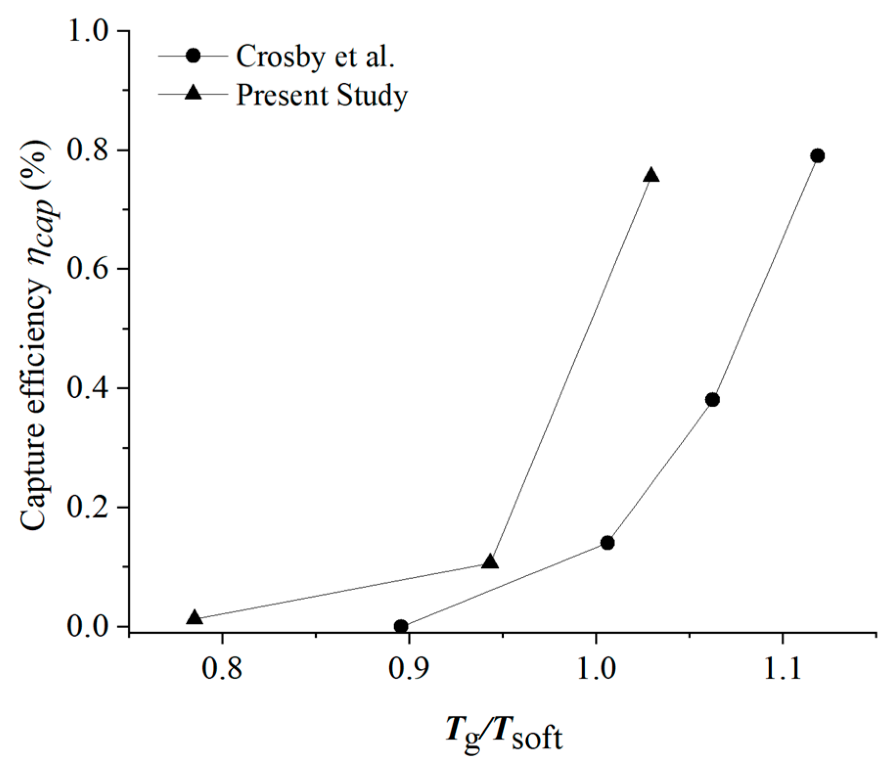
10] conducted deposition tests using three kinds of coal-water fuels. They noted that deposition mass was proportional to the gas temperature, varying from 1253 to 1373 K. Crosby et al. [11] used a flat plate to study the independent effect of particle size and gas temperature on ash deposition. It was found that the deposition rate increased with increasing gas temperature and particle size. Ai et al. [12] explored the effects of particle size on deposition by using a flat plate with film-cooling holes angled at 45°. Bonilla et al. [13] further explored the particle size effect on the CFM56-5B nozzle guide vane. Lundgreen et al. [14] designed a new turbine cascade to study deposition on the nozzle guide vane surface at inlet temperatures of 1090, 1265, and 1350 °C. It was found that the amount of deposition on the pressure surface increased as the inlet temperature increased. Due to harsh test conditions and high cost, the deposition test at temperatures representative of the actual engines was simulated by those at an ambient temperature, based on similarity laws. Albert et al. [15,16] simulated particle deposition at the turbine vane leading edge and on the pressure surface in a low-speed wind tunnel facility by matching the Stokes numbers and thermal scaling parameter (TSP). Zhang et al. [17,18] carried out deposition tests at different mainstream temperatures and velocities with wax particles and found deposition mass increased initially and then decreased with the mainstream temperature or velocity. Zhang et al. [19] also investigated the effect of the angle of attack and particle concentration on the wax deposition behavior.
The numerical model was another strategy for predicting particle deposition behavior. Brach and Dunn [20] proposed the critical velocity model, and they assumed that deposition would occur when particle velocity is below a certain threshold. Bons et al. [21] improved the critical model and simulated the particle deposition on the turbine blade surface numerically. Sreedharan and Tafti [22] modeled the ash particle deposition on a flat plate angled at 45° based on the critical viscosity method. They predicted an exponential increase in the deposition rate with mainstream temperature, which was consistent with the experimental results. Considering the effect of particle deposition on the geometry structure, Liu et al. [23] developed a numerical model for simulating particle deposition with the dynamic mesh morphing technique. The increase in deposition mass was noted, with particle size increasing. Connolly et al. [24] also utilized the dynamic mesh method to simulate particle deposition and found that the flow field was affected dramatically by deposition buildup.
Complex chemical and physical processes were involved in the particle deposition, including multiphase flow and heat transfer. It is difficult to predict the deposition formation accurately only by numerical models. Experimental study is a necessary part in the exploration of a complex process. However, turbine inlet temperatures have increased considerably with advances in gas turbine technology. This creates a demand for advances in material and blade-cooling techniques. Most deposition tests are still performed at turbine inlet temperatures around 1500 K. Hence, deposition tests at higher temperature could be beneficial to obtain more accurate results. To the best of our knowledge, there are few examples of any deposition test that runs at higher temperatures than those in the present work. The effect of the angle of attack was also explored using the turbine guide blade at changeable angles of attack.
In this work, we designed a turbine blade-fixing device by which the angle of attack can be adjusted to a desired angle manually. The objectives are to investigate the independent effects of gas temperature and angle of attack on particle deposition on a turbine blade with six rows of film-cooling holes, in a deposition facility equipped with an internally staged single-tube combustor with a single module, by adjusting the fuel–air ratio and the installation angle of the fixing device, respectively.

2. Experimental Facility and Method

2.1. Experimental Facility and Test Model

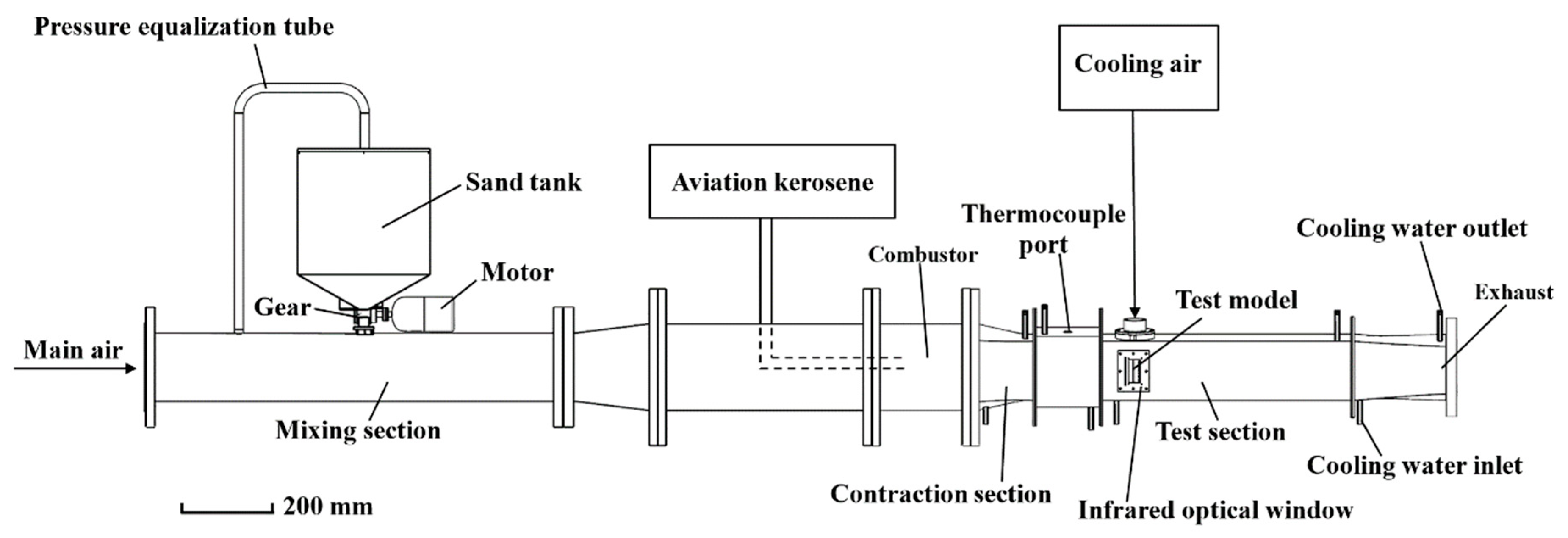
Experiments were performed in a turbine deposition facility equipped with an internally staged single-tube combustor with a single module, seeded with sand particles to replicate the particle deposition on the turbine blade. The experimental system consists of the mixing section, combustor, test section and other components (Figure 1). 
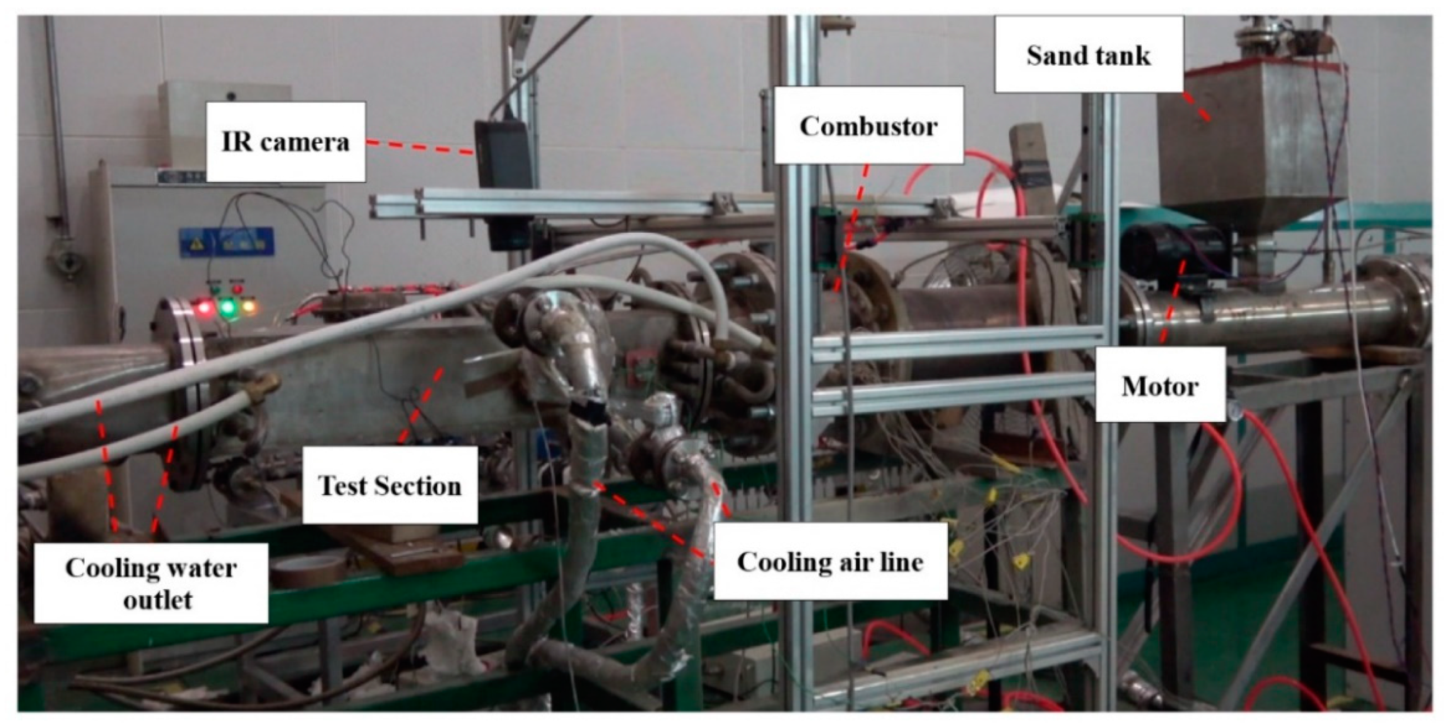
Figure 2 shows the photograph of the deposition facility with the single-tube combustor. Mainstream inlet was supplied from a high-pressure storage tank at a pressure around 0.6 MPa to achieve the mass flow rate range from 0 to 0.6 kg/s. It was preheated using a 550 kW electric heater with an upper limit of 773 K. The inlet temperature was adjusted by controlling the fuel–air ratio and measured using three S-type platinum–rhodium thermocouples located at the entrance to the test section, just upstream of the test model. The thermocouple has a relative uncertainty of 0.25%. Sand particles were injected into the mixing section from the sand tank, driven by a 15-tooth gear and an electric motor. The pressure equilibration tube connected the sand tank to the mixing section, aimed at achieving a balance between them. The gear was accelerated by the motor, producing a mass flow rate between 0 and 3 g/s, depending on the motor rotation speed. The uncertainty of the mass flow rate was 4.02%. Sand particles from the sand tank were entrained into the mainstream flow and entered the combustor. When heated by the hot gas, some sand particles became molten. Parts of particles might be deposited on the test model with film-cooling holes fixed by a holder in the test section. RP-3 aviation kerosene was pumped out of an underground fuel tank through a solenoid valve on the way to the combustor. Fuel mass flow rate was measured by the gear flow meter (STAUFF VC 0.4, Germany) with a relative uncertainty of 0.3%.
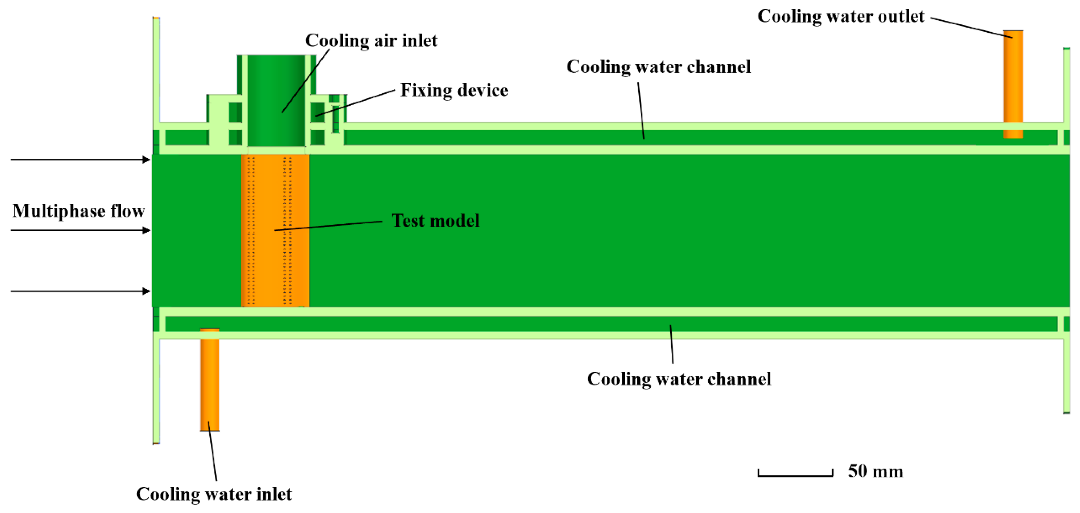
Figure 3 shows the structure of the test section. It was 1.2 m in length. The cross-section was a 0.1 × 0.1 m square. The inner wall of the test section employed water-cooling schemes to help protect the materials from heat generated during high temperature operations. Cooling water was supplied from three tubes upstream of the test model and one downstream of the test model on the exterior wall.
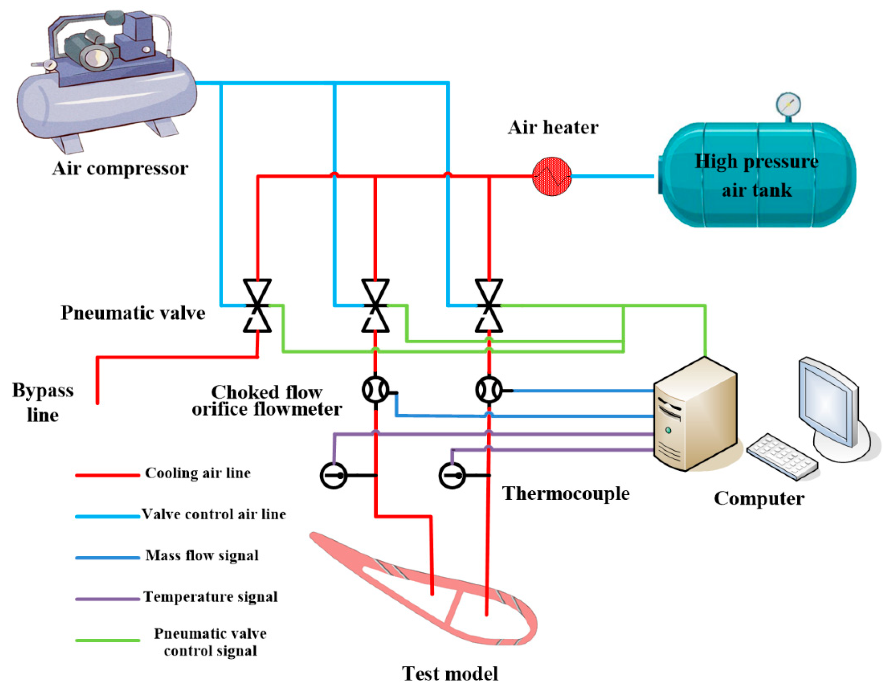
The schematics of the cooling air system is presented in Figure 4. The cooling air was supplied by a high-pressure air tank and then heated by an electrical heater. The heated cooling air was divided into three parts: two for blade cooling (cooling air lines) and one for residue air emission and heater protection (bypass line). The cooling air flow rate was measured by an orifice flowmeter with a maximum capacity of 10 g/s and a relative uncertainty of 0.6%. It could be controlled by three pneumatic valves installed on three cooling air lines, respectively. The cooling air temperature was detected using two resistance thermometers with a maximum capacity of 573 K and an uncertainty of ±0.5 K.
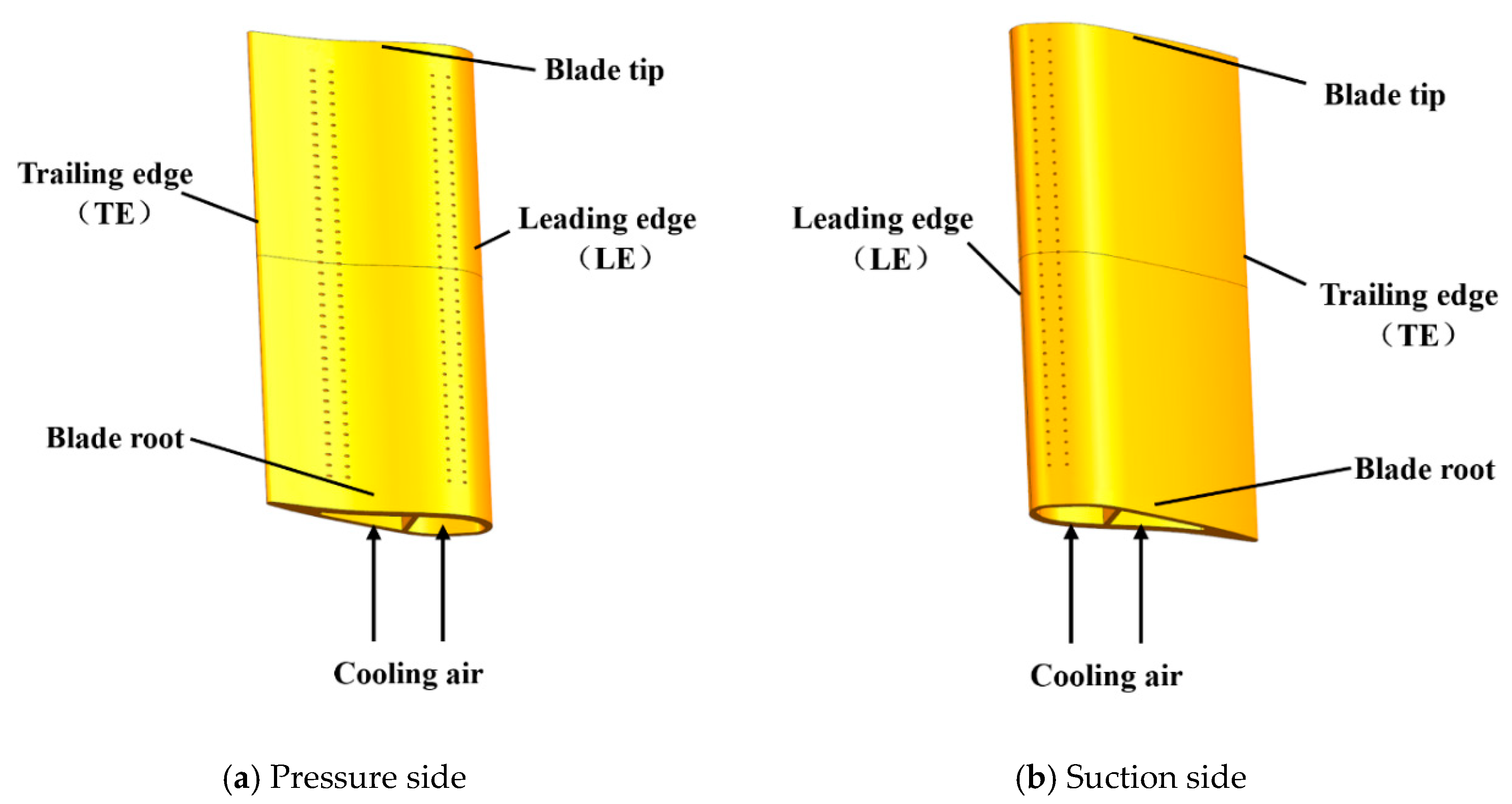
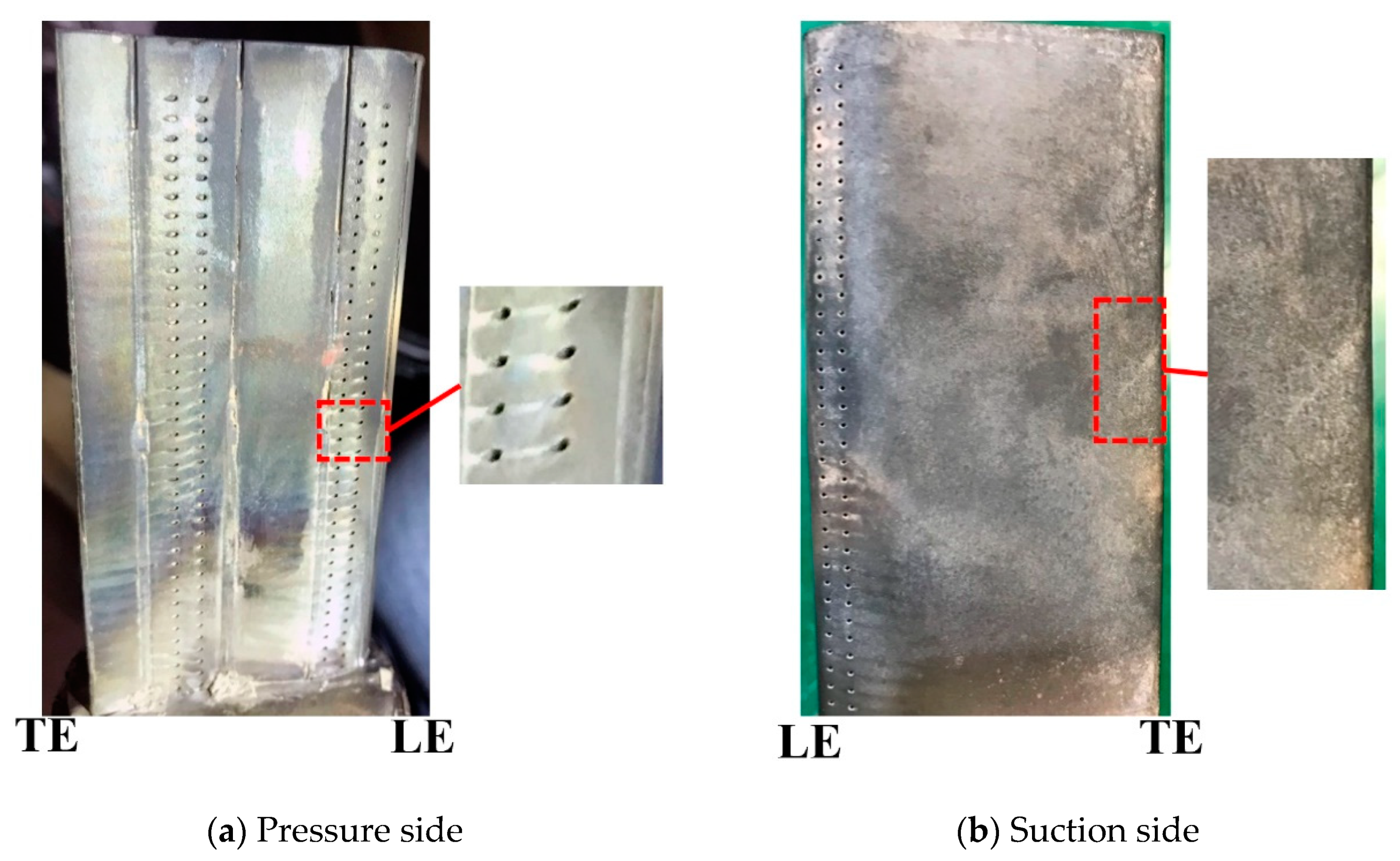
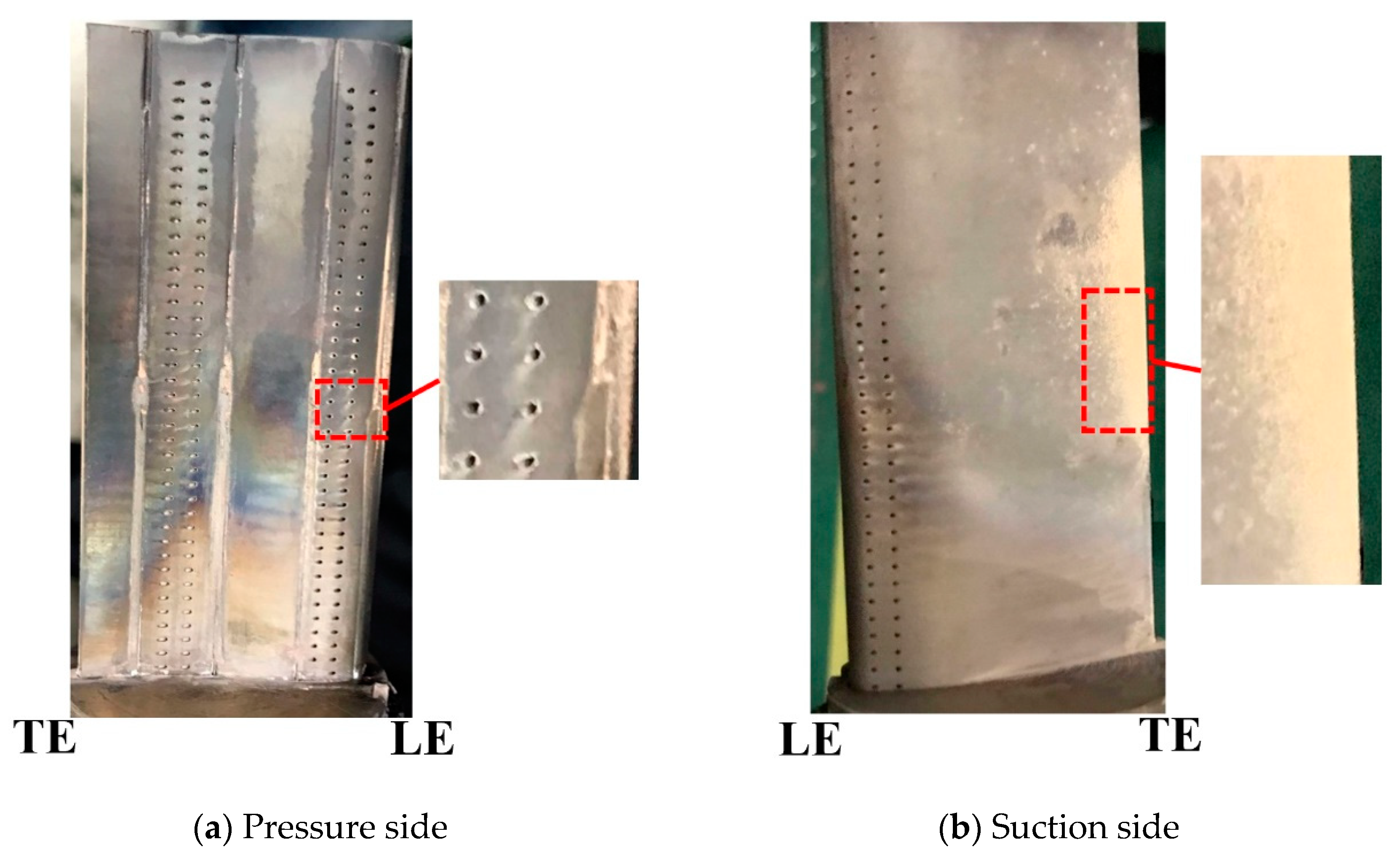
A turbine guide blade was designed as the test model in this study, made of the nickel-based superalloy GH4169 processed by additive manufacturing technology. The test model can be set at an angle of attack ranging from 10° to 40° by adjusting the rotation angle of the test model fixing device. As is shown in Figure 5, the chord length of the test model is 50 mm, half of the blade height. Forty film-cooling holes are arranged on each row along the spanwise direction of the model. The film-cooling holes are cylindrical with a diameter of 0.5 mm and the hole spacing is 1.88 mm. In total, 240 film-cooling holes were distributed across six rows: four rows on the pressure surface of the blade and the other rows on the suction surface. The inner cooling cavity was separated into two by a central partition with a thickness of 1.2 mm (
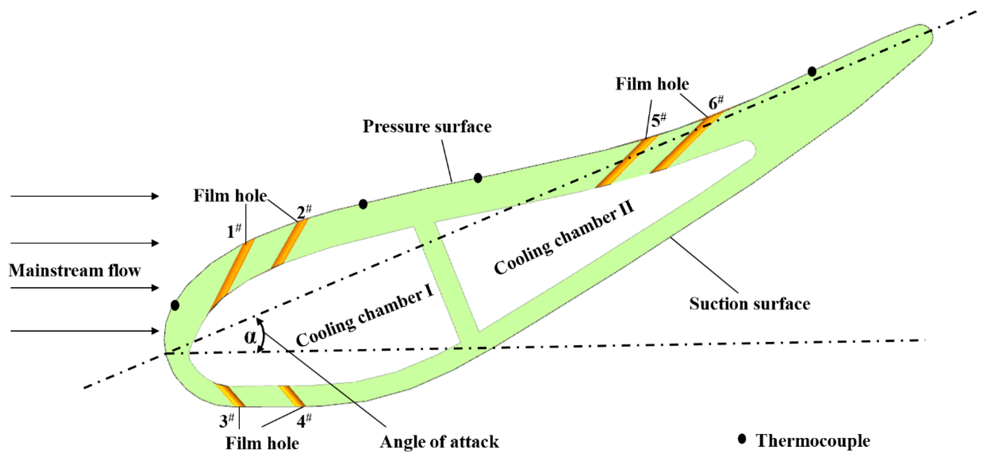
Figure 6). Four rows on the suction and pressure surfaces were connected to cooling cavity I near the leading edge, while two rows on the pressure surface were connected to cooling cavity II near the trailing edge. Cooling air was supplied from the blade root to inner cooling cavities I and II through two cooling air lines. The exhausted air was emitted from the inner cavity through film-cooling holes.
An infrared inspection window, designed to allow infrared radiation to transmit to the outside environment, was installed above the upper surface of the test model to collect infrared temperature data for an infrared camera (FLIR A655sc, relative certainty: 2%). The K-type thermocouple with an uncertainty of 2 K serves as the method used for IR camera calibration. It had four data collection points on the blade pressure surface. The resulting deposition mass was measured by the analytical balance (METTLER TOLEDO XPR 3003S, Switzerland, precision grade: 1 mg). Pre-test and post-test blade profiles were obtained by a 3D scanner with a precision up to 5 μm (Tianyuan OKIO-5M-100, China). The differences in geometry were acquired to provide the deposition thickness.

2.2. Sand Preparation and Characterization

Gas turbine engines operate in different environments that feature various kinds of airborne particles, such as volcanic ash, coal dust, sand particles and others. The distribution and composition varies among those foreign particles. However, the physical and chemical properties of the ingested particles would exert direct effects on the deposition behaviors [25], which further affect the engine performance. The test sand in the sand tank, adopted for the deposition tests, is prepared according to the USA military standard (MIL-STD-3033) [26] to simulate the effects on the engine blade through environments that contain sand particles.
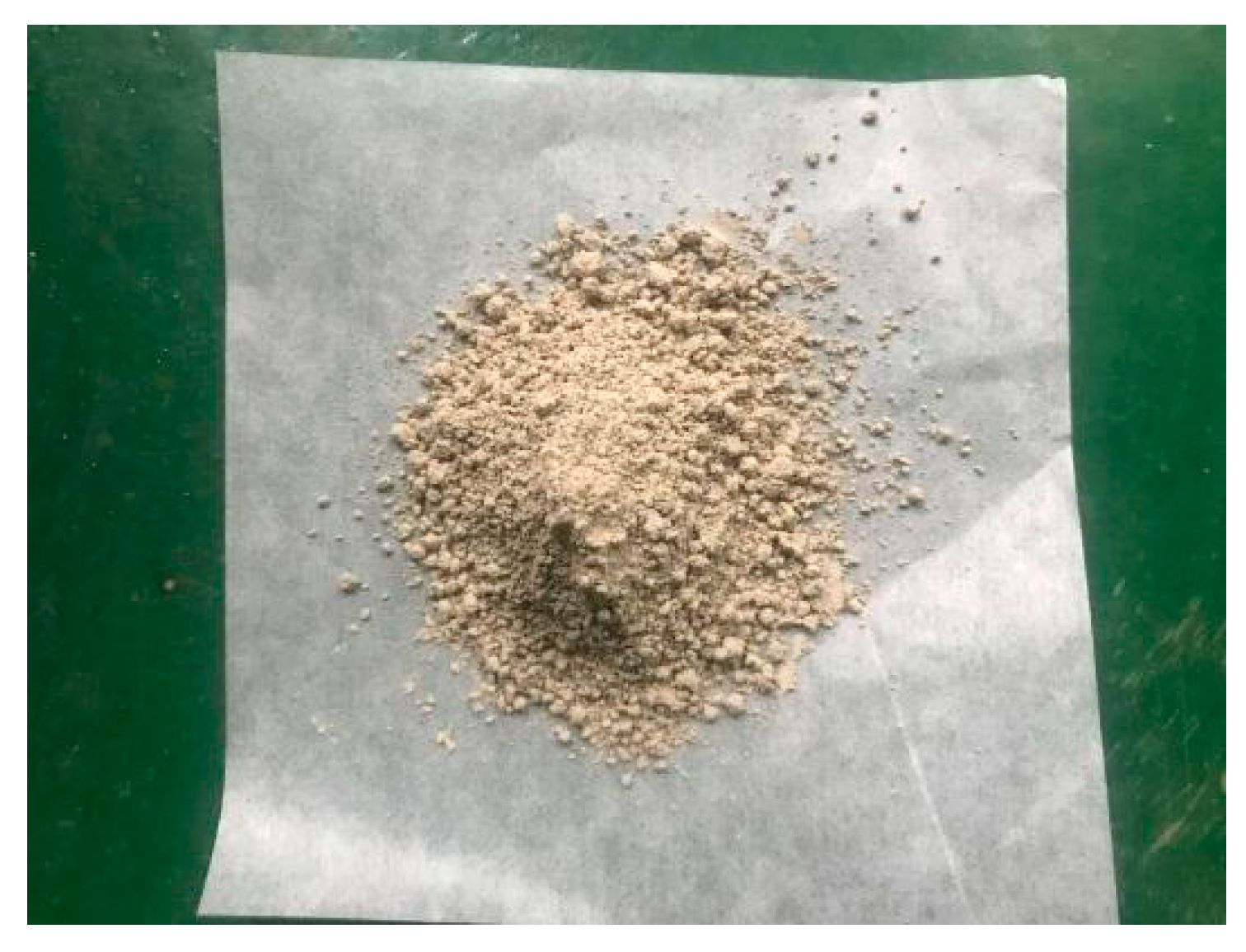
The test sand was a light brown powder (
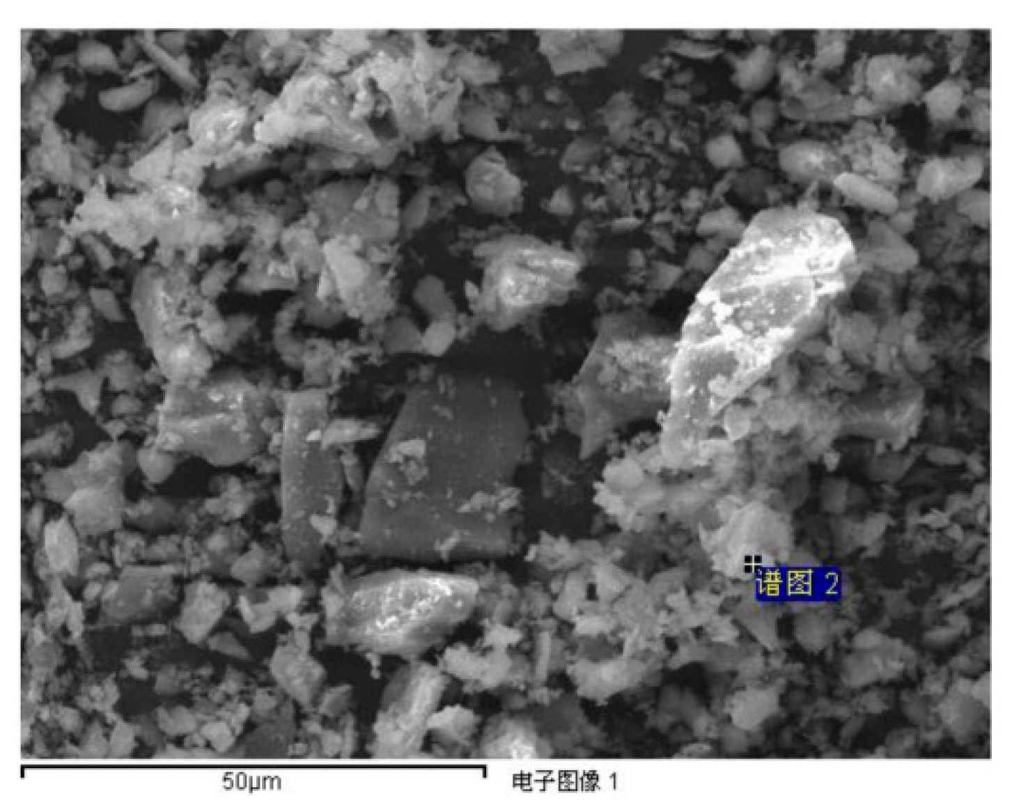
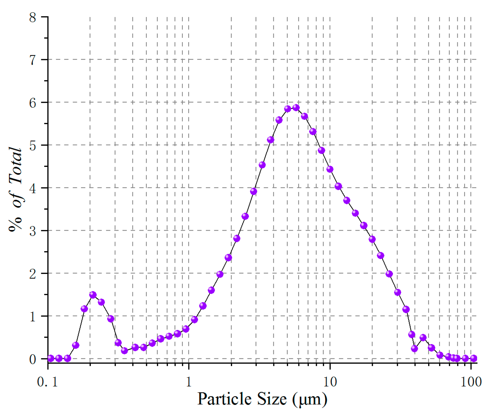
Figure 7) that can hardly be dissolved in water. Its density is roughly 2.65 times that of water. The morphology of the test sand was characterized by a scanning electron microscope (SEM, Hitachi model S-4800, Japan). The sand particle size distribution was determined on a laser particle size analyzer (LPSA, Malvern Mastersizer 2000, UK). SEM imaging reveals that the sand sample is primarily composed of angular, discrete particles of different sizes, which have edges and corners with bump surface (Figure 8). Slight agglomerates of fine particles are observed on the large sand particle surface. The mean particle sizes are mainly distributed between 1 and 10 μm, confirmed by laser particle size analysis (Figure 9). Particle size is one of the major factors in determining the particle flow and deposition behavior. Deposition on the blade is a result of inertial particle transport. However, the particle trajectory is influenced by aerodynamic forces acting upon the ingested particles when they are carried with gas through the combustor. The aerodynamic forces are highly dependent on particle size. For example, friction is proportional to the square of the particle diameter. The mean particle size at the turbine inlet is found to be mainly below 50 μm from previous studies. Thus, the sand sample adopted herein is representative of that ingested by the turbine.
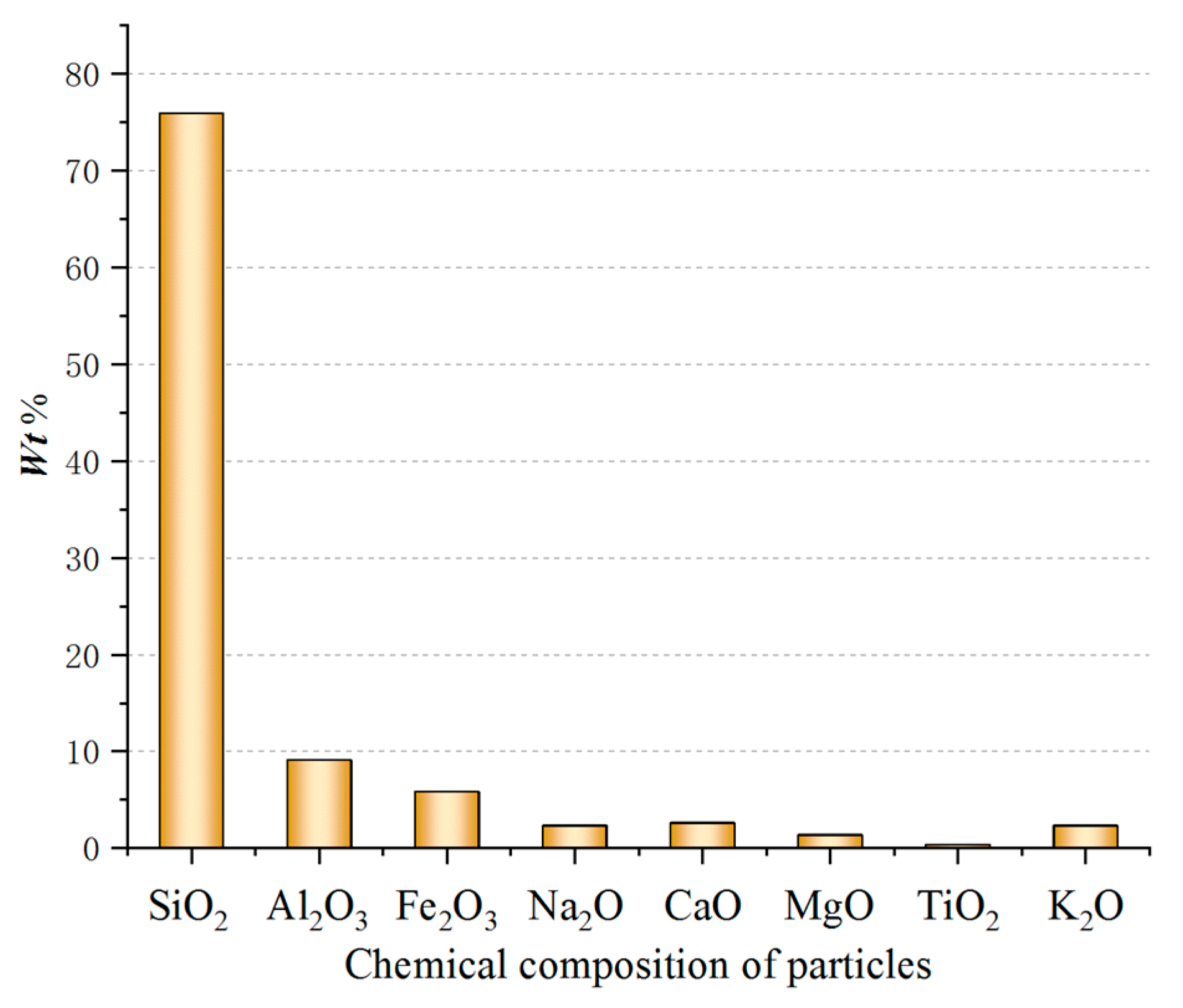
The elemental composition was provided using a ThermoFisher Scientific X-ray photoelectron spectrometer (XPS, ESCALAB 250Xi, USA). The XPS survey spectra confirms the existence of oxygen (O), silicon (Si), aluminium (Al), iron (Fe), potassium (K), solium (Na), calcium (Ca), magnesium (Mg) and titanium (Ti) in the test sand. Apart from oxygen, Si was the most abundant element, indicating that silicon dioxide was the major phase in the sand, amounting to more than 70% of the test sand (Figure 10). The rest of the constituents were metal oxides.

2.3. Experimental Parameters

The main operating parameters of the deposition test facility are listed in 
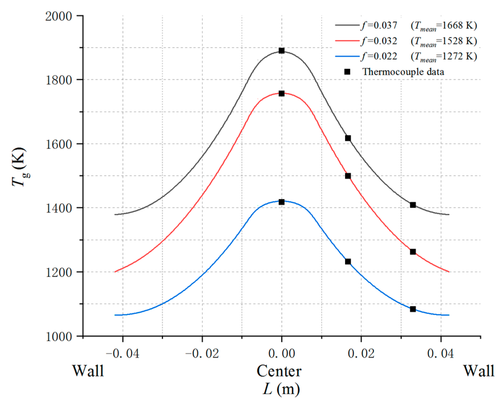
Table 1. The outlet temperatures of modern gas turbine combustors vary from 1200 to 2100 K depending on the engine purposes. For the combustor utilized herein, the upper limit of the fuel–air ratio was 0.037, with a maximum temperature rise of 1300 K. The combustor outlet temperature was controlled by adjusting fuel–air ratio and holding inlet temperature constant. It was measured by three thermocouples, located at the center of the cross-section of the test section. The field temperature was symmetrically distributed along the axis of the fuel nozzle based on the characteristics of the internally staged single-tube combustor [27]. The temperature reached the highest level in the center and the lowest level near the wall, as shown in the fitted quadratic curve of gas temperature data at the outlet cross-section of the combustor (Figure 11). At the fuel–air ratio of 0.037, the temperature peak at the outlet section is approximately 1890 K, while it decreases to 1400 K near the wall. The mean temperature at the test section inlet was determined using definite integrals. It decreased as the fuel–air ratio decreased. The average values were calculated to be 1668, 1528 and 1272 K, corresponding to the fuel–air ratios of 0.037, 0.032, and 0.022, respectively. The main variables of the deposition tests are listed in Table 2. The mainstream inlet flow is a fully developed turbulent flow at Reynolds number Re ≈ 1.01 × 10⁵ based on the mainstream velocity and cross-sectional width upstream of the test model.

2.4. Test Procedures

The deposition test procedure is listed below:
(1) The test model was carefully cleared before three-dimensional (3D) shape and weight measurements. The test model geometric profile was obtained by a 3D scanner. The initial mass of the test model was measured by the analytical balance, recorded as the pre-test mass;
(2) After the geometric and weight data of the test model were acquired, it was mounted in the fixing device at a specified angle of attack. The positions were marked to make sure the model was always located at the same place and orientation before the test restarted. Then, the test device status was checked, such as the air heater and IR camera;
(3) The cooling air system was turned on and then the cooling air flow rate was adjusted and stabilized. Subsequently, the online temperature measurement system was switched on, including the infrared thermometer and thermocouples;
(4) The air heater was opened to preheat the mainstream flow;
(5) The fuel feed pump was started to add the fuel. With fuel and air being supplied, the combustor burned the mix after ignition. The fuel–air ratio was adjusted to the specified value to control the inlet temperature at the test section;
(6) The temperature at the combustor exit was monitored by thermocouples. The temperatures of mainstream flow and test model surface were both allowed to reach steady state. Once the deposition facility reached the steady state, the variable speed motor, which controlled the sand seeding system, was driven. The sand mass flow rate was set at the specified value for different test cases. The test model temperature data were recorded by the IR camera;
(7) At the end of the deposition test, the fuel pump and cooling air system were turned off in sequence. The test model was removed when it cooled down to room temperature;
(8) The test model was reweighed by the analytical balance, recorded as the post-test mass and the deposition mass was calculated by subtracting the pre-test mass from the post-test mass. The 3D scanning was utilized again to acquire the geometric shape of the test model. The deposition thickness was obtained by comparing the 3D geometric profile data of the test model, and then the test model with particle deposition on.

3. Results and Discussion

3.1. The Effect of Gas Temperature on the Particle Deposition

The first test series was performed to explore the effect of the gas temperature on the deposition behavior. The gas temperature was varied from 1272 to 1668 K and the rest of the experimental parameters were held constant, such as the angle of attack, pressure and total mass of the sand. Deposition on the test model at a gas temperature of 1272 K is presented in Figure 12. On the pressure side, small amounts of sand particles could be observed at the exit of each film-cooling hole on the bottom half of the blade. Light yellow sand deposition was observed on the middle of the blade leading edge where the surface temperature was the highest. For the suction side, sand deposition was sparsely distributed downstream of the film-cooling holes. No evident deposition was observed on the rest of surface.
Figure 13 shows an image of the test model at a gas temperature of 1528 K. Compared with deposition at 1272 K, the deposition area expanded along the leading edge on the pressure side and the trailing edge on the suction side, while no obvious change in deposition was detected on the remnant positions. For the suction side, evident sand deposition was noted on the middle region of the trailing edge, which could result from the high temperature at the half height of the blade and the absence of film-cooling holes.
The deposition phenomena depend on the particle phase, which is determined by the soften temperature [25]. The soften temperature further depends on the chemical composition. The soften temperature of the test sand in this study, which was prepared based on the standard test sand, was estimated using Equation (1) [28].
T s o f t = 10.75 SiO 2 + 13.03 Al 2 O 3 5.28 Fe 2 O 3 5.88 CaO 10.28 MgO + 3.75 a + 453
where a = 100 − (SiO2 + Al2O3 + Fe2O3 + CaO + MgO), SiO2, Al2O3, Fe2O3, CaO, and MgO represent the mass fraction of individual oxide in the sand sample, respectively. When the silica content is larger than 60%, the soften temperature for the sand is figured out to be 1620 K. The effect of gas temperature above the soften temperature was also explored. The fuel–air ratio was set to the upper limit for the single-tube combustor to achieve the highest gas temperature of 1668 K, and the temperature of the mainstream flow center even reached up to 1890 K. Figure 14 shows the particle deposition on the pressure and suction sides of the test model at a gas temperature of 1668 K. For the pressure side, the deposition was concentrated downstream of the cooling hole exit at the half height of the blade. Distinct deposition bands were noted downstream of the cooling hole exit near the blade root. A deposition layer was evenly distributed at the leading edge with a notch formed on the edge. Deposition flaking might be attributed to the continuously accumulating deposition weight, difference in thermal expansion coefficients and shear stress [11]. Deposition became thinner near blade tip, due to a small clearance gap between the blade tip and the test section wall, through which the mainstream laden with sand particles would flow. This kind of flow was driven by the pressure difference between the upper and lower surfaces of the test model, which was similar to the airfoil tip vortex. In addition, the sand particles with low inertia followed the mainstream flow well. Therefore, they were deposited at the trailing edge of the suction side near the blade tip, as presented in Figure 14b. The deposition was distributed densely in a grain-like pattern at the half height of the trailing edge, while it gradually changed to the sparse needle-like distribution near the blade tip. Distinct deposition was also found downstream of the film-cooling hole exits. Evident deposition formed on the middle region of the leading edge and further spread to the mid-chord region along the mainstream direction. Figure 15 shows the deposition thickness comparison between the pressure and suction sides at different gas temperatures ranging from 1272 to 1668 K. The deposition thickness increased as the gas temperature increased. For the pressure side, the deposition thickness at a gas temperature of 1668 K is far above the deposition thickness in other cases. For the suction side, the deposition thickness was at its maximum at the trailing edge.
Two tests were performed at a gas temperature below the softening temperature (1620 K), while duplicate tests were performed at a gas temperature of 1668 K and the highest exit temperature point reached up to 1890 K, which is representative of the temperature in a modern gas turbine engine. Figure 16 presents the temperature fields of the blade pressure surface at different gas temperatures. The highest temperature on the blade surface rose from 800 to 1200 K as the gas temperature increased from 1272 to 1668 K. Surface temperature also contributed to the deposition buildup, as concluded by Laycock et al. Obviously, the deposition mass increased with the increase in gas temperature (Figure 17). At a gas temperature of 1272 K (the highest temperature point reached 1427 K), the deposition mass was smaller than that at a gas temperature of 1528 K (the hottest point reached 1766 K above the softening temperature). However, the deposition mass increased remarkably between 1528 and 1668 K. The deposition behavior is dependent on the surface properties of the blade and particle, especially the Young’s modulus, based on El-Batsh et al.’s studies [29]. The adhesion ability of sand particles is enhanced when the Young’s modulus of the blade material and particle decreases. The Young’s modulus of the particle decreases as the mainstream temperature rises [30]. Besides, the blade temperature rises as the mainstream temperature increases. High surface temperature accounts for the low Young’s modulus and high adhesion ability. Consequently, particles stick to the blade surface more easily at a higher mainstream temperature, resulting in more deposition.
Deposition behavior is characterized by the capture efficiency. The turbine guide blade capture efficiency was calculated as
η c a p = m d e p m t o t a l
where mdep is the deposition mass of the sand particles and mtotal is the total mass of the sand particles fed into the deposition facility. Figure 18 shows the trend of the capture efficiency in this work and Crosby’s [11]. The increasing trend is similar to that of Crosby et al. They investigated the independent effect of gas temperature on coal ash deposition. They found that capture efficiency decreased with a drop in gas temperature for the test model without film-cooling holes. It increased markedly at the gas temperature above the threshold, around 1233 K, for coal ash deposition. The dramatic increase was because the particles had a great tendency to rebound and detach from the blade below the softening temperature but adhere to the blade above it [22]. The capture efficiency lines in this study are all above those of Crosby, due to the difference in test models. The test model is a flat plate without film-cooling holes at an angle of attack of 45° in Crosby’s study, while it is a blade with six rows of film-cooling holes at an angle of attack of 25° in this study. The deposition mass on the blade comes from the total deposition on both the pressure and suction sides. Moreover, a vortex structure would form on the blade surface with film-cooling holes under the interaction of the mainstream flow and cooling air flow. The structure accounts for the deposition buildup downstream of the film-cooling holes. Consequently, deposition mass depends on the combined effect of the particle physical state, blade surface temperature, and the test model itself.

3.2. The Effect of Angle of Attack on the Particle Deposition

The second test series was performed to explore the individual effect of the angle of attack in the 10°–40° range on the deposition behavior. As depicted in Figure 19, deposition mainly formed at the 50% spanwise location on the pressure surface since it experienced the highest thermal load. For the case of angle of attack α = 10°, the deposition formed downstream of the two rows of film-cooling holes near the leading edge, as if it had been blown out of those holes. A continuous deposition layer was formed near the trailing edge. The deposition expanded to the region around the film-cooling holes near the leading edge at an angle of attack of 25°, then distributed unevenly and concentrated at the midspan. At an angle of attack of 40°, thick deposition with a lumpy appearance occurred at the midspan, and even blocked several film-cooling holes near the leading edge. The amount of deposition formed downstream of the cooling holes dropped compared with those between 10° and 25°. Only sparse deposition could be found near the trailing edge film-cooling holes.
Figure 20 shows the thickness of deposition on the pressure surface for cases at 10°, 25° and 40°. At an angle of attack of 10°, deposition thickness increased along the streamwise direction. It reached the maximum downstream of the trailing edge cooling holes. At an angle of attack of 40°, deposition thickness reached the highest level downstream of the leading edge cooling holes. Figure 21 presents a close view of the film-cooling holes near the blade trailing region. It was found that deposition almost disappeared downstream of the film-cooling holes in the test case of 40° when compared with the test case of 10°. For the small angle of attack case, the film-cooling jet and mainstream would mix downstream of the film-cooling holes. The interaction between them formed the jet vortices, further resulting in the particle deposition downstream of the hole exits. However, when it came to the big angle of attack case, the film-cooling jet flow was fully suppressed by the mainstream flow. The cooling air flowed closely along the blade surface, accounting for less deposition downstream.
Figure 22 shows the increase in the area of deposition regions, with the angle of attack increasing on the suction surface. It is noted that the deposition region even stretched to the 50% chord position. This is because the windward area increased with the increasing angle of attack. The pressure difference between the pressure and suction sides would increase, resulting in more particles being transported to the suction side and more deposition on this side.
The deposition thickness increased as the angle of attack increased on the suction surface trailing edge and the regions between film-cooling holes (Figure 23). At an angle of attack of 40°, the thickness decreased downstream of the film-cooling holes while it increased, and soon decreased at 10° and 25°. When the dimensionless distance exceeded 0.4, the deposition thickness increased with the chordwise distance.
The deposition mass increased with the angle of attack (Figure 24). This is because more sand particles, which follow the flow with good fidelity, tend to impinge and deposit on the blade surface with larger windward area. Taltavull et al. [31] found that the particle sticking rate increased as the normal collision angle (or angle of attack) increased. Also, the increased pressure difference caused by the angle of attack change contributes to the particle deposition on the suction side. In short, the attack angle affects the deposition mass and the area of the deposition region near the trailing edge.
Figure 25 shows the comparison of the capture efficiency in this work and that of Ai et al. Though the increasing trends are similar, the line slope decreases at angles of attack in the 25° to 40° range in this study, while it increases remarkably in the 30° to 45° range in Ai et al.’s work. The difference could be explained by tunnel blockage ratios. At the larger blockage ratio adopted by Ai et al., the mainstream laden with particles impinges directly on the test model surface and resulting deposition accumulates significantly in the large angle of attack cases. In this study, the section length of the test section is double the blade chord length. The ratio of the cross-section area of the test section to the windward area of the blade is far less than that in Ai et al.’s study. The mainstream laden with particles is prone to flow around the blade surface and resulting deposition builds up slightly, even in the large angle of attack cases.

4. Conclusions

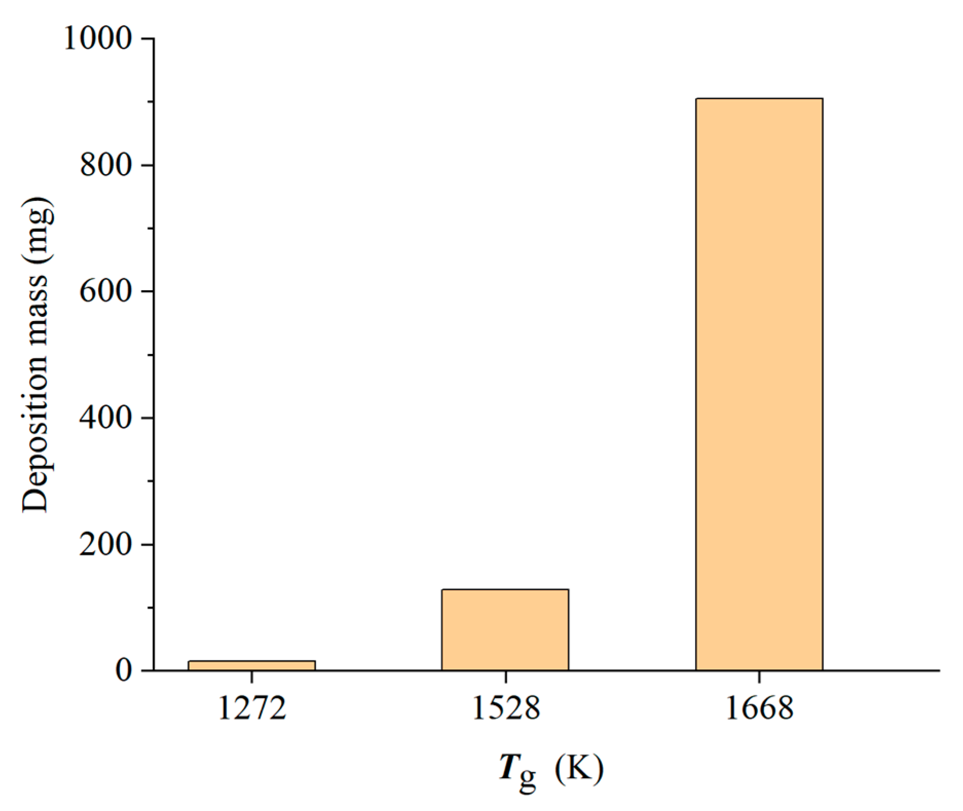
A deposition test facility equipped with an internally staged single-tube combustor with a single module was used to study the effect of the gas temperature and angle of attack on the deposition distribution, mass and thickness. All deposition tests were performed on a turbine blade with six rows of film-cooling holes at turbine representative temperatures (1272 to 1668 K) provided by the combustor with a maximum fuel–air ratio of 0.037. Test sand was prepared based on the MIL-STD-3033 standard sand and injected into the mainstream flow to simulate the effects on the turbine blade exposed to environments containing sand particles.
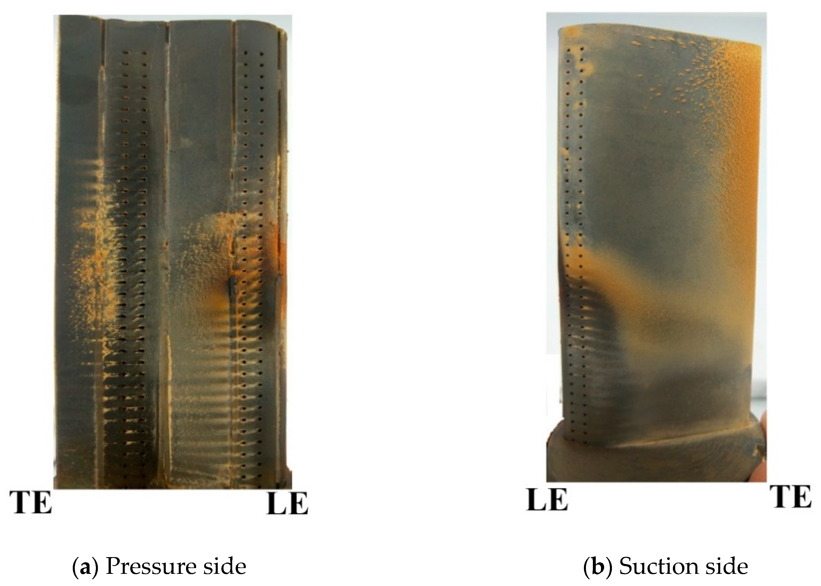
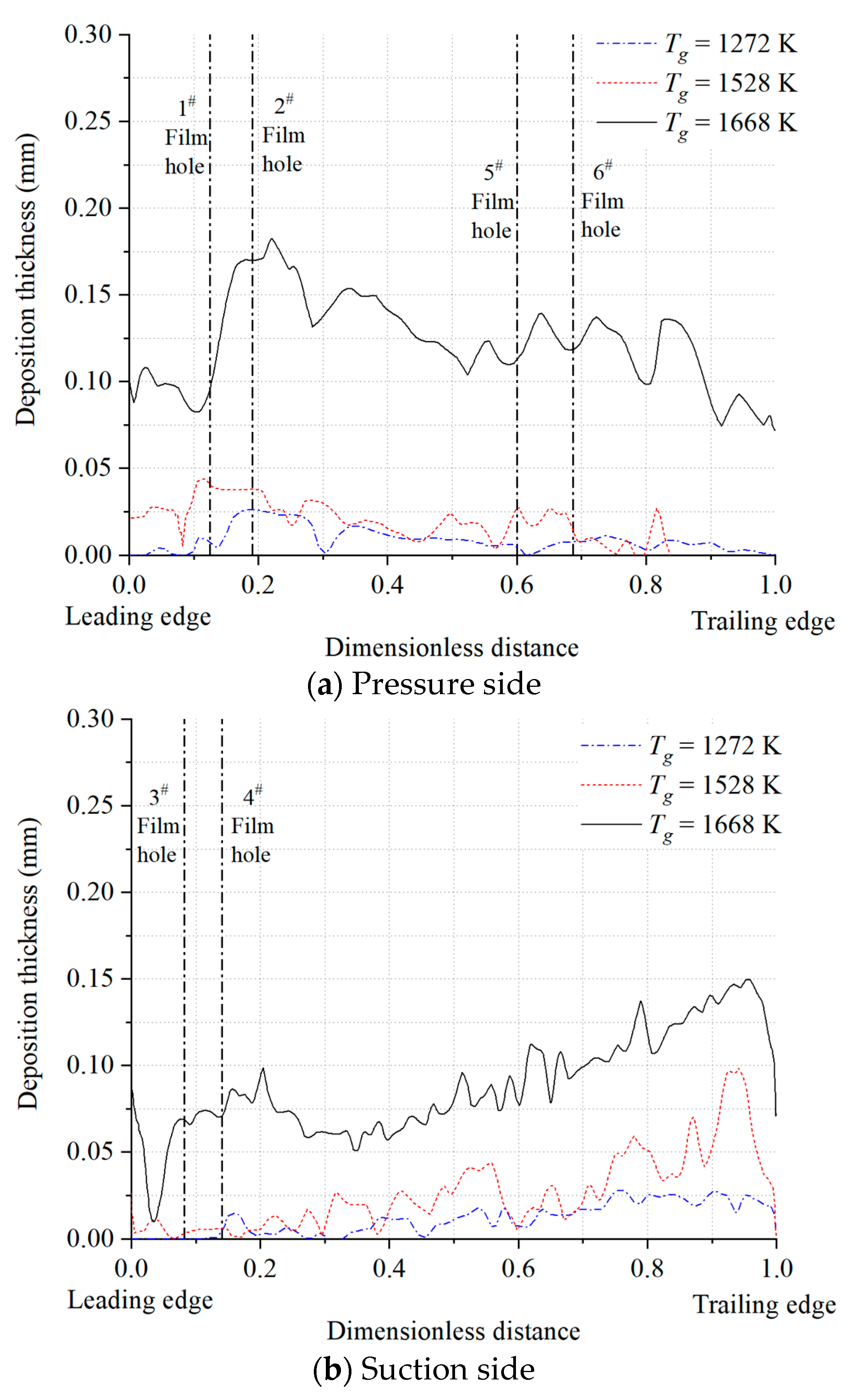
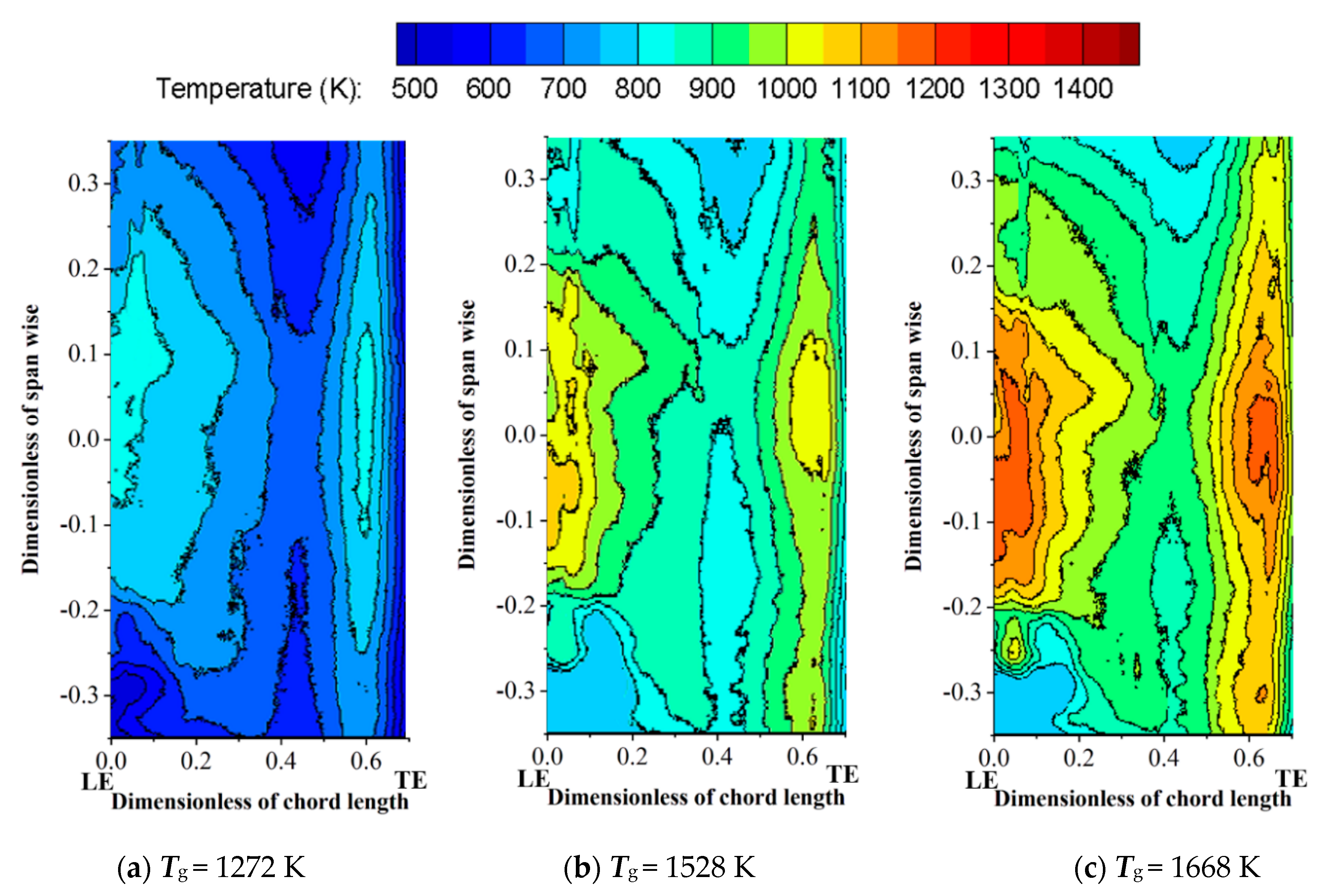
Gas temperature was assumed to have a marked effect on deposition as the gas temperature varied from 1272 to 1668 K with the adjustment of the fuel–air ratio. There exists a threshold temperature as a function of the particle chemical composition. Deposition accumulated on the blade surface faster when gas temperature was increased above it. Evident deposition at a gas temperature of 1668 K suggested that sand deposition mainly formed on the aft portion of the suction surface and downstream of the film-cooling holes on the pressure surface.
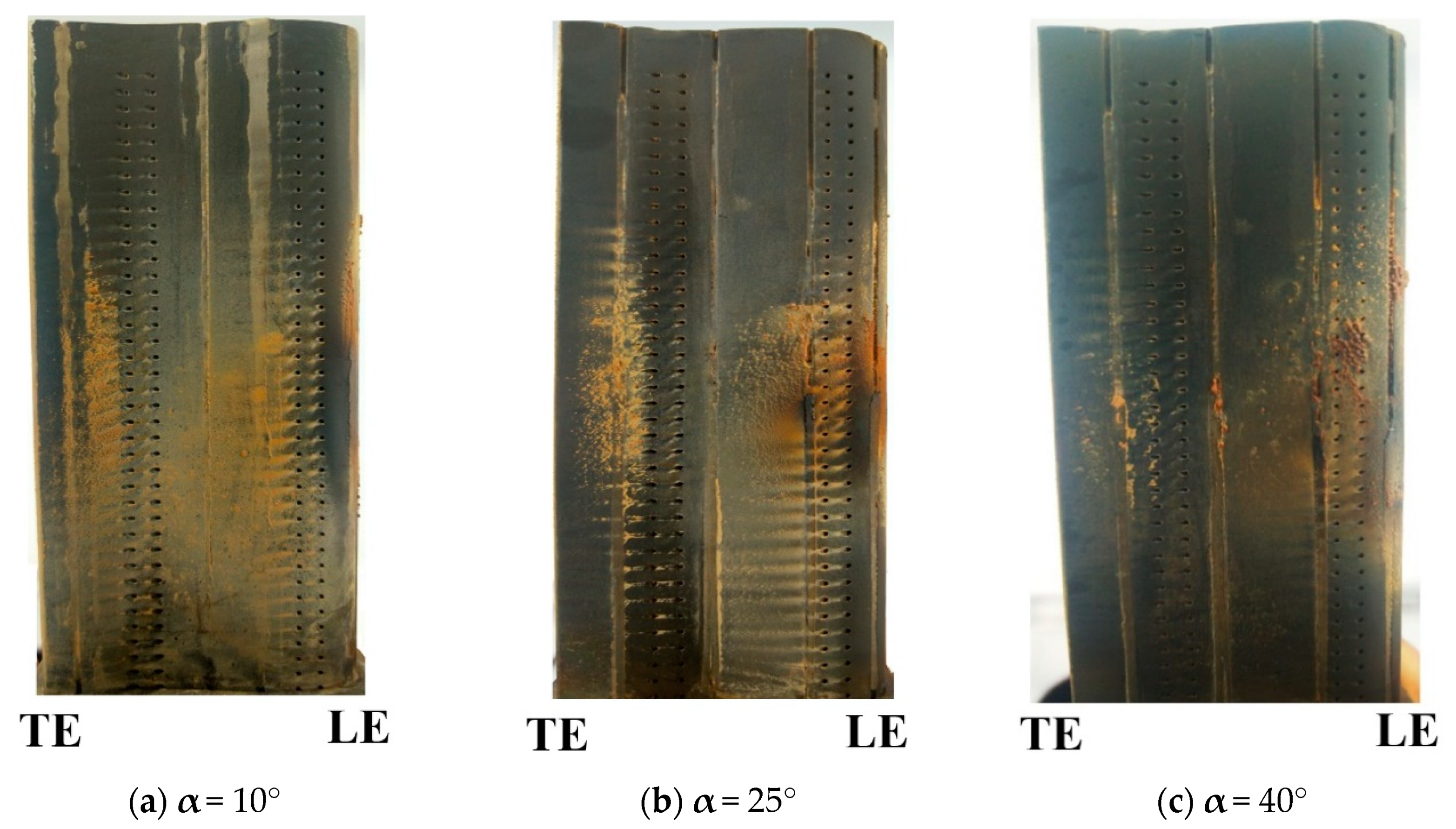
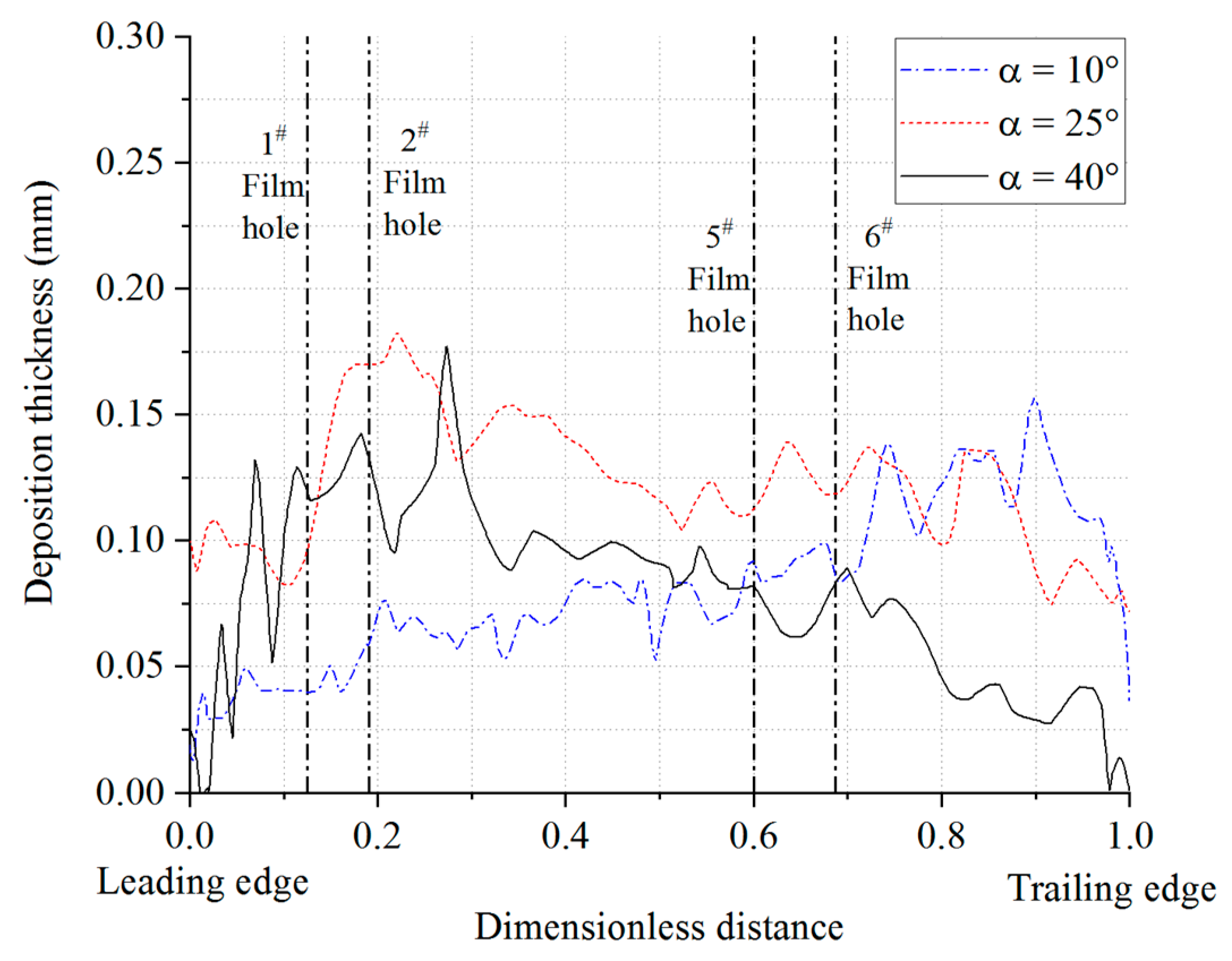
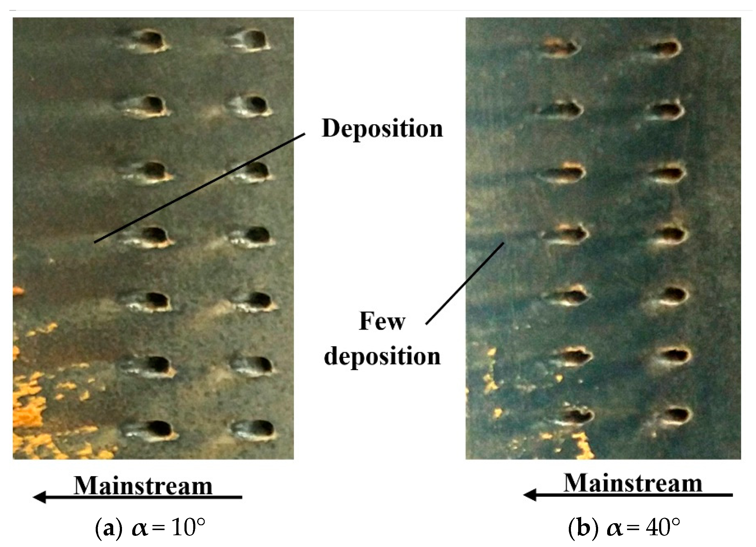
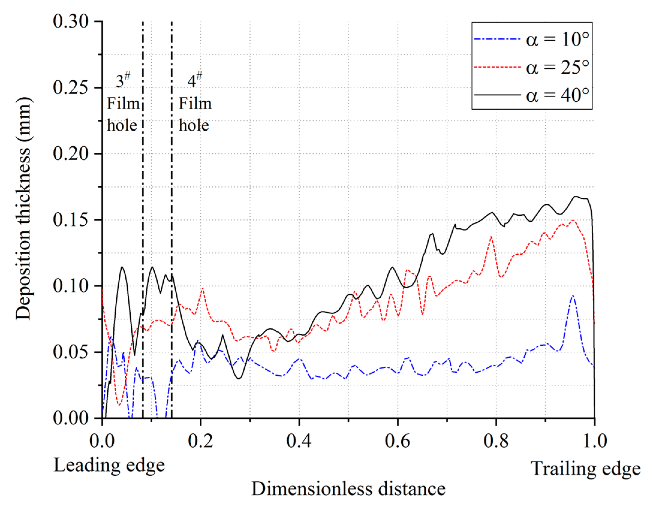
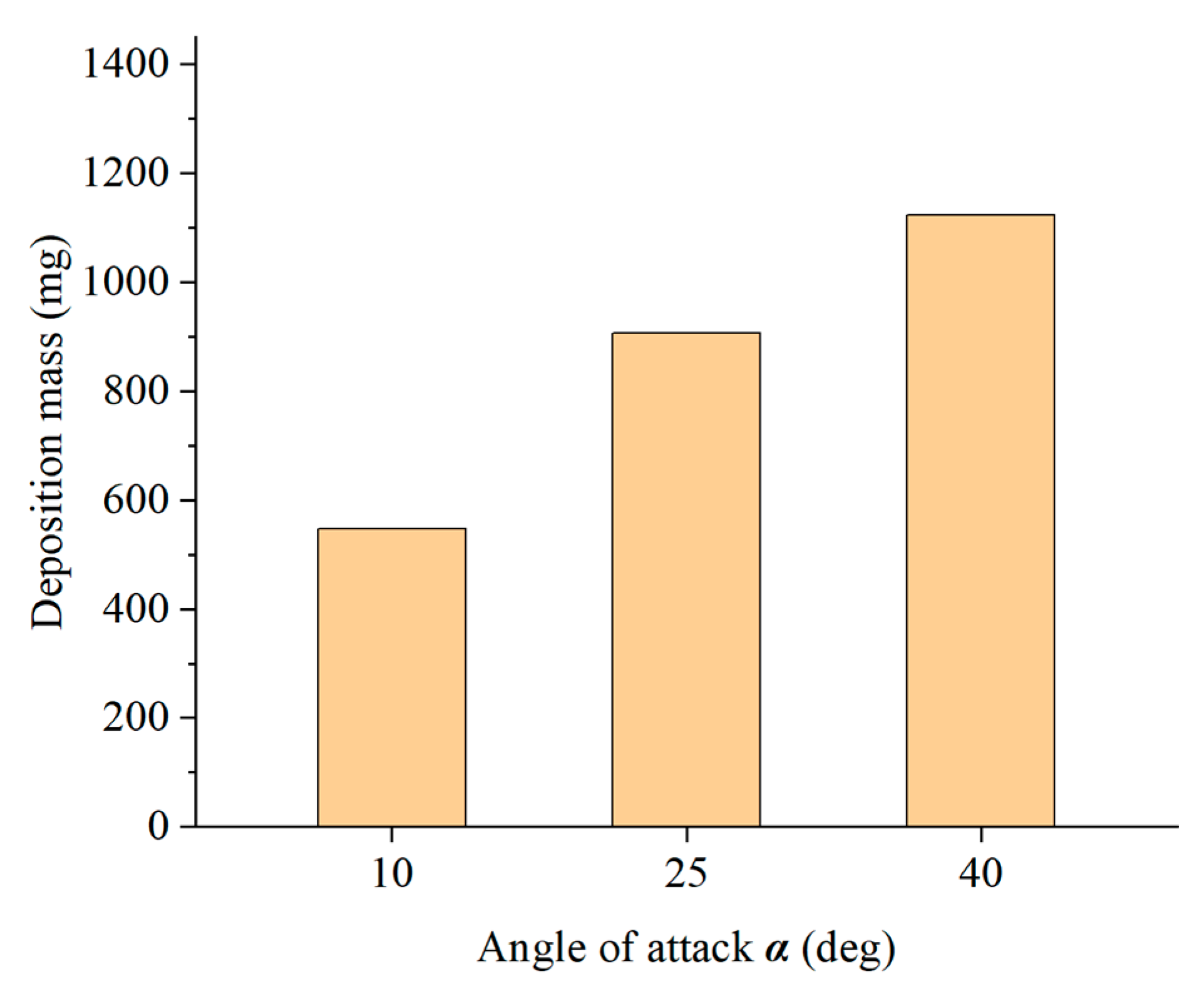
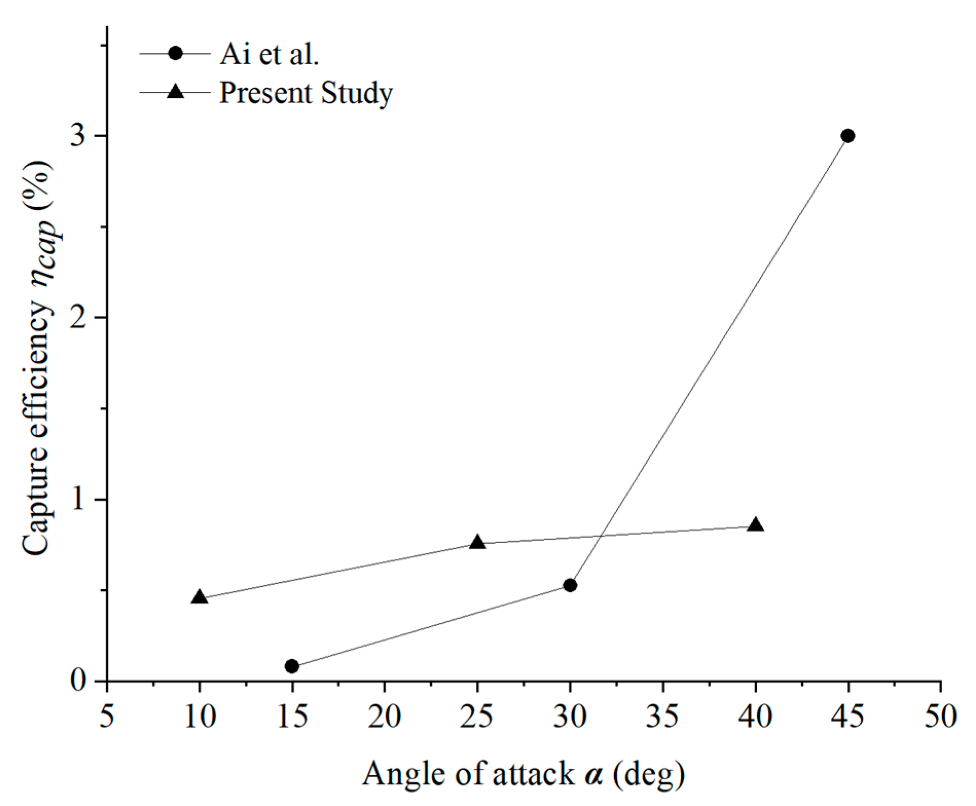
The second test series was run by varying the angle of attack from 10° to 40° at a gas temperature of 1668 K. The deposition mass increased with the angle of attack. The increase in capture efficiency slowed down as the angle of attack rose from 25° to 40° when compared with that the capture efficiency of the angle of attack that rose from 10° to 25°. The deposition distribution downstream of the film-cooling holes depends on angle of attack for the blade pressure surface. In the small angle of attack case, jet vortices formed under the interaction between the film-cooling jet and mainstream, further resulting in the particle deposition downstream of the cooling holes. For the large angle of attack case, the film-cooling jet flow would be fully suppressed by the mainstream flow. The cooling air flows close to the blade surface, accounting for less deposition downstream.

Author Contributions

Investigation, writing—original draft preparation, F.Z.; resources, Z.L. (Zhengang Liu); supervision, Z.L. (Zhenxia Liu); data curation, W.D. All authors have read and agreed to the published version of the manuscript.

Funding

This research received no external funding.

Conflicts of Interest

The authors declare no conflict of interest.

References

  1. Bons, J.P.; Crosby, J.; Wammack, J.E.; Bentley, B.I.; Fletcher, T.H. High-pressure turbine deposition in land-based gas turbines from various synfuels. J. Eng. Gas Turbines Power 2007, 129, 135–143. [Google Scholar] [CrossRef] [Green Version]
  2. Hamed, A.; Tabakoff, W.C.; Wenglarz, R.V. Erosion and deposition in turbomachinery. J. Propuls. Power 2006, 22, 350–360. [Google Scholar] [CrossRef] [Green Version]
  3. Tabakoff, W. Review—Turbomachinery performance deterioration exposed to solid particulates environment. J. Fluids Eng. 1984, 106, 125–134. [Google Scholar] [CrossRef]
  4. Dunn, M.G.; Moller, J.C.; Adams, R.M. Performance deterioration of a turbofan and a turbojet engine upon exposure to a dust environment. J. Eng. Gas Turbines Power 1987, 109, 336–343. [Google Scholar] [CrossRef]
  5. Ai, W.; Murray, N.; Fletcher, T.H.; Harding, S.; Lewis, S.; Bons, J.P. Deposition near film cooling holes on a high pressure turbine vane. J. Turbomach. 2012, 134, 041013. [Google Scholar] [CrossRef]
  6. Boulanger, A.; Patel, H.; Hutchinson, J.; Deshong, W.; Xu, W.; Ng, W.; Ekkad, S. Preliminary experimental investigation of initial onset of sand deposition in the turbine section of gas turbines. In Proceedings of the ASME Turbo Expo, Seoul, Korea, 13–17 June 2016. [Google Scholar] [CrossRef]
  7. Jensen, J.W.; Squire, S.W.; Bons, J.P.; Fletcher, T.H. Simulated land-based turbine deposits generated in an accelerated deposition facility. J. Turbomach. 2005, 127, 462–470. [Google Scholar] [CrossRef]
  8. Kim, J.; Dunn, M.G.; Baran, A.J. Deposition of volcanic materials in the hot sections of two gas turbine engines. J. Eng. Gas Turbines Power 1993, 115, 641–651. [Google Scholar] [CrossRef]
  9. Wammack, J.E.; Crosby, J.; Fletcher, D.; Bons, J.P.; Fletcher, T.H. Evolution of surface deposits on a high-pressure turbine blade-Part I: Physical characteristics. J. Turbomach. 2008, 130, 021020. [Google Scholar] [CrossRef]
  10. Wenglarz, R.A.; Fox, R.A. Physical aspects of deposition from coal-water fuels under gas turbine conditions. J. Eng. Gas Turbines Power 1990, 112, 9–14. [Google Scholar] [CrossRef]
  11. Crosby, J.M.; Lewis, S.; Bons, J.P.; Ai, W.; Fletcher, T.H. Effects of temperature and particle size on deposition in land based turbines. J. Eng. Gas Turbines Power 2008, 130, 819–825. [Google Scholar] [CrossRef] [Green Version]
  12. Ai, W.; Laycock, R.G.; Rappleye, D.S.; Fletcher, T.H.; Bons, J.P. Effect of particle size and trench configuration on deposition from fine coal flyash near film cooling holes. Energy Fuels 2011, 25, 1066–1076. [Google Scholar] [CrossRef]
  13. Bonilla, C.; Webb, J.; Clum, C.; Casaday, B.; Brewer, E.; Bons, J.P. The effect of particle size and film cooling on nozzle guide vane deposition. J. Eng. Gas Turbines Power 2012, 134, 1–8. [Google Scholar] [CrossRef]
  14. Lundgreen, R.; Sacco, C.; Prenter, R.; Prenter, R.; Bons, J.P. Temperature effects on nozzle guide vane deposition in a new turbine cascade rig. In Proceedings of the ASME Turbo Expo, Seoul, Korea, 13–17 June 2016. [Google Scholar] [CrossRef]
  15. Albert, J.E.; Bogard, D.G. Experimental simulation of contaminant deposition on a film cooled turbine airfoil leading edge. J. Turbomach. 2012, 134, 1–10. [Google Scholar] [CrossRef]
  16. Albert, J.E.; Bogard, D.G. Measurements of adiabatic film and overall cooling effectiveness on a turbine vane pressure side with a trench. J. Turbomach. 2013, 135, 1–11. [Google Scholar] [CrossRef]
  17. Zhang, F.; Liu, Z.; Liu, Y. Experimental study of particle deposition on surface at different mainstream velocity and temperature. Energies 2019, 12, 747. [Google Scholar] [CrossRef] [Green Version]
  18. Liu, Z.; Zhang, F.; Liu, Y. An experimental study on the effects of a film cooling configuration and mainstream temperature on depositing. J. Therm. Sci. 2019, 28, 360–369. [Google Scholar] [CrossRef]
  19. Zhang, F.; Liu, Z.; Liu, Y. Experimental simulation of particle deposition on turbine blade surface with different free stream conditions. J. Propuls. Technol. 2019, 40, 1536–1545. [Google Scholar] [CrossRef]
  20. Brach, R.; Dunn, P. A mathematical model of the impact and adhesion of microsphers. Aerosol Sci. Technol. 1992, 16, 1–14. [Google Scholar] [CrossRef]
  21. Bons, J.P.; Prenter, R.; Whitaker, S. A simple physics-based model for particle rebound and deposition in turbomachinery. J. Turbomach. 2017, 139, 1–12. [Google Scholar] [CrossRef]
  22. Sreedharan, S.S.; Tafti, D.K. Composition dependent model for the prediction of syngas ash deposition in turbine gas hotpath. Int. J. Heat Fluid Flow 2011, 32, 201–211. [Google Scholar] [CrossRef]
  23. Liu, Z.; Zhang, F. A numerical model for simulating liquid particles deposition on surface. In Proceedings of the ASME Turbo Expo, Oslo, Norway, 11–15 June 2018. [Google Scholar] [CrossRef]
  24. Connolly, J.; Forsyth, P.; McGilvray, M.; Gillespie, D. The use of fluid-solid cell transformation to model volcanic ash deposition within a gas turbine hot component. In Proceedings of the ASME Turbo Expo, Oslo, Norway, 11–15 June 2018. [Google Scholar] [CrossRef]
  25. Song, W.; Lavallée, Y.; Hess, K.U.; Kueppers, U.; Cimarelli, C.; Dingwell, D.B. Volcanic ash melting under conditions relevant to ash turbine interactions. Nat. Commun. 2016, 7, 10795. [Google Scholar] [CrossRef] [PubMed] [Green Version]
  26. US Military Standards. MIL-STD-3033, Particle/Sand Erosion Testing of Rotor Blade Protective Material; Department of Defense: Washington, DC, USA, 2010; pp. 1–11. [Google Scholar]
  27. Yu, H.; Suo, J.; Zhu, P.; Zheng, L. The characteristic of flow field and emissions of a concentric staged Lean Direct Injection (LDI) combustor. J. Northwest. Polytech. Univ. 2018, 36, 816–823. [Google Scholar] [CrossRef]
  28. Yin, C.; Luo, Z.; Ni, M.; Cen, K. Predicting coal ash fusion temperature with a back-propagation neural network model. Fuel 1998, 77, 1777–1782. [Google Scholar] [CrossRef]
  29. El-Batsh, H.; Haselbacher, H. Numerical investigation of the effect of ash particle deposition on the flow field through turbine cascades. In Proceedings of the ASME Turbo Expo, Amsterdam, The Netherlands, 3–6 June 2002. [Google Scholar] [CrossRef]
  30. Ai, W.G.; Fletcher, T.H. Computational analysis of conjugate heat transfer and particulate deposition on a high pressure turbine vane. J. Turbomach. 2012, 134, 041020. [Google Scholar] [CrossRef] [Green Version]
  31. Taltavull, C.; Dean, J.; Clyne, T.W. Adhesion of volcanic ash particles under controlled conditions and implications for their deposition in gas turbines. Adv. Eng. Mater. 2016, 18, 803–813. [Google Scholar] [CrossRef] [Green Version]
Figure 1. Schematics of the turbine deposition facility.
Energies 13 00811 g001
Figure 2. Photograph of the turbine deposition facility.
Energies 13 00811 g002
Figure 3. Schematics of the test section.
Energies 13 00811 g003
Figure 4. Schematics of the cooling air system.
Energies 13 00811 g004
Figure 5. CAD drawing of the test model.
Energies 13 00811 g005
Figure 6. Cross-section details of the test blade.
Energies 13 00811 g006
Figure 7. Photograph of the test sand.
Energies 13 00811 g007
Figure 8. SEM image of test sand particles.
Energies 13 00811 g008
Figure 9. Particle size distribution.
Energies 13 00811 g009
Figure 10. Chemical composition of the test sand.
Energies 13 00811 g010
Figure 11. Temperature distribution at the test section inlet (combustor outlet).
Energies 13 00811 g011
Figure 12. Photos of the sand deposition on the (a) pressure and (b) suction sides of the test model at the mainstream temperature of 1272 K.
Energies 13 00811 g012
Figure 13. Photos of the sand deposition on the (a) pressure and (b) suction sides of the test model at the mainstream temperature of 1528 K.
Energies 13 00811 g013
Figure 14. Photos of the sand deposition on the (a) pressure and (b) suction sides of the test model at the mainstream temperature of 1668 K.
Energies 13 00811 g014
Figure 15. Surface deposition thickness plot for the test model at gas temperatures of 1272, 1528 and 1668 K (cross-section at midspan).
Energies 13 00811 g015
Figure 16. Temperature fields of the blade pressure surface at gas temperatures of 1272, 1528 and 1668 K before the sand particle seeding system was commenced.
Energies 13 00811 g016
Figure 17. Effect of gas temperature on the deposition mass.
Energies 13 00811 g017
Figure 18. Comparison of the capture efficiency between present study and Crosby et al.’s [11].
Energies 13 00811 g018
Figure 19. Images of the post-test blade pressure side at the angle of attack: (a) 10°, (b) 25°, and (c) 40°.
Energies 13 00811 g019
Figure 20. Surface deposition thickness plot for the pressure side of the test model angled at 10°, 25° and 40° (cross-section at midspan).
Energies 13 00811 g020
Figure 21. Close views of deposition in the cases of 10° and 40°.
Energies 13 00811 g021
Figure 22. Images of the post-test blade suction side at different angles of attack: (a) 10°, (b) 25°, and (c) 40°.
Energies 13 00811 g022
Figure 23. Surface deposit thickness plot for the suction side of the test models angled at 10°, 25° and 40° (cross-section at midspan).
Energies 13 00811 g023
Figure 24. Comparison of deposition mass at angles of attack of 10°, 25°, and 40°.
Energies 13 00811 g024
Figure 25. Comparison of the capture efficiency between Ai et al. [12] and present study.
Energies 13 00811 g025
Table 1. Main operating parameters of the test facility.
Mainstream Pressure (MPa)Mainstream Mass Flow Rate (kg/s)Combustor Inlet Temperature (K)Fuel-Air Ratio fCooling Air Mass Flow Rate (kg/s)Cooling Air Temperature (K)
0.3850.475430.022−0.0370.0103358
Table 2. Deposition test variables.
Case No.Mainstream Gas Temperature Tg (K)Angle of Attack α (deg)Total Mass of Sand Particles (g)Test Time t (min)
112722512030
2152825
3166825
4166810
5166840

