Article

Simulation Analysis on the Heat Performance of Deep Borehole Heat Exchangers in Medium-Depth Geothermal Heat Pump Systems

Department of Building Science, Tsinghua University, Beijing 100084, China
*
Author to whom correspondence should be addressed.
Energies 2020, 13(3), 754; https://doi.org/10.3390/en13030754
Submission received: 9 December 2019 / Revised: 24 January 2020 / Accepted: 4 February 2020 / Published: 8 February 2020
(This article belongs to the Section G: Energy and Buildings)

Abstract

:
Deep borehole heat exchangers (DBHEs) extract heat from the medium-depth geothermal energy with the depth of 2–3 km and provide high-temperature heat source for the medium-depth geothermal heat pump systems (MD-GHPs). This paper focuses on the heat transfer performance of DBHEs, where field tests and simulation are conducted to analyze the heat transfer process and the influence factors. Results identify that the heat transfer performance is greatly influenced by geothermal properties of the ground, thermal properties and depth of DBHEs and operation parameters, which could be classified into external factors, internal factors and synergic adjustment. In addition, the long-term operation effects are analyzed with the simulation, results show that with inlet water temperature setting at 20 °C and flow rate setting at 6.0 kg/s, the average outlet water temperature only drops 0.99 °C and the average heat extraction drops 9.5% after 20-years operation. Therefore, it demonstrates that the medium-depth geothermal energy can serve as the high-temperature heat source for heat pump systems stably and reliably. The results from this study can be potentially used to guide the system design and optimization of DBHEs.

1. Introduction

Space heating plays an important role and accounts for nearly 21% of the energy consumption in buildings [1]. For the energy saving as well as sustainable development, various technologies with renewable energy has been studied and applied for space heating, especially for the utilization of geothermal energy [2]. In order to use geothermal energy more rationally and efficiently, the ground-coupled heat pump systems (GCHPs) have been applied and aroused great interesting in last two decades [3]. However, with numerous studies carried out to examine the practical energy performance of GCHPs, various problems have been identified. Among which the occupation of huge spaces for constructions [4] as well as the thermal imbalance of the ground [5,6,7,8,9] were the two typical issues thus limiting the application of GCHPs.
To solve these typical issues, a straightforward method is to utilize the deeper geothermal energy. Recently, the medium-depth geothermal energy, with depth of nearly 2–3 km and temperature around 70–90 °C, has been exploited and applied for space heating. Different from the exploiting of underground water to extract geothermal energy straightly, the utilization of medium-depth geothermal energy in this paper refers to the method that using a closed loop system to extract heat through heat transfer process. This method was first introduced and carried out in America and Europe, where the outlet water temperature of deep borehole heat exchangers (DBHEs) could reach nearly 98 °C in Hawaii [10] and 40 °C in Switzerland [11]. Besides, this method was successfully used as heat source in a university in Germany [12]. Recently, this method was applied for space heating with heat pump systems in China and field test was conducted in previous study [13]. Results showed that the outlet water temperature from DBHEs with depth of 2500 m could reach 34.7 °C with heat extraction of 273 kW per DBHE, which provides a stable and high-temperature heat source for heat pump systems.
As mentioned above, the DBHEs extract heat from medium-depth geothermal energy through the heat transfer between heat transfer medium and soil and rocks around. Therefore, the studies and analysis of the heat transfer process and the influencing factors have significant importance, which determines the heat transfer performance of DBHEs and further influence the energy performance of heat pump systems. Previous research mainly focused on the simulation and mathematical models. Ingersoll [14] and Eskilson [15] presented the infinite line source and the finite line source model respectively to examine the temperature distribution of rock-soil around shallow borehole heat exchangers (BHEs). Diao [16] and Lamarche [17] improved the finite line source model, which is easily incorporated into computer programs. As for the numerical simulation of BHEs, finite element method (FEM) [18], finite volume method (FVM) [19] and finite difference method (FDM) [20] were the main analysis methods based on discrete method. Then the Laplace transform methods [21] was used to solve the transient heat conduction equation and analyzed the heat transfer process.
With the simulation, previous research examined the heat transfer performance of DBHEs. Chen [22] developed a fitted expression based on 3D numerical models to analyze the influence of inlet water temperature, flow rate and the depth of ground heat exchangers (GHEs) on heat transfer performance of GHEs. H. Holmberg [23] pointed out that with the increasing of depth and flow rate, the heat extraction capacity will increase. However, the depth of GHEs in the simulation only varied from 300–1000 m, which is not deep enough for medium-depth geothermal energy. For DBHEs, Lous [24] conducted a simulation to analyze the heat transfer performance of a vertical 5 km coaxial DBHE. Over 25-year periods of operation, the heat extraction could still reach 125–600 kW with flow rate of 150–600 m3/d, which proved the stability and feasibility of DBHEs. However, since the depth of DBHEs is too deep, the system is hard to be applied widely under the limit of engineering grade and the great investment costs. L. Fang’s simulation [25] was more close to the practical project where the depth of DBHE is 2000 m. Results also showed that the increasing of flow rate and depth of DBHE as well as the geothermal gradient would increase the heat transfer capacity. It also indicated that a high-resistance inner pipe would improve the overall heat extraction capacity. Besides, the flow direction of ground water has been discussed, thus the inlet water is suggested to flow through the outer tube. Kong [26] used both analytical and numerical methods to evaluate the capacity of DBHE with representative parameters in northern China. Results showed that the sustainable heat extraction rates in all continuous extraction scenarios are less than 150 W/m. Besides, the sensitivity analysis indicated that the depth of borehole is not a significant influencing factor to the heat extraction rate, while the heat conductivity of surrounding formation is critical. This study provide a scientific method to analyze the performance and its influence factor. However, due to the lack of engineering experience, the physical parameters of DBHE deviated from the actual values, especially about the heat conductivity coefficient of the outer pipe, thus the simulation results failed to match the field test results. Other researchers also focused on the numerical simulation with FVM model to analyze the heat transfer performance of DBHE [27,28,29]. Better than previous studies, field tests were conducted thus the accuracy of simulation could be checked with operational data. Nevertheless, the filed test was conducted in a steady condition thus the dynamic simulation effect failed to be checked. Besides, the boundary conditions both for radial direction and depth direction have not been discussed qualitatively and quantificationally.
In summary, due to lack of detailed field-based measurements and analysis of generation and conduction process of medium-depth geothermal energy, the physical model in previous research deviates from practical conditions, thus the calculated results can hardly reflects the actual operation process. Consequently, this paper analyze the generation and heat transfer process of medium-depth geothermal energy at first to discuss and determine the boundary conditions. Then based on field test results under different operation conditions, a simulation with the FVM is conducted to analyze the heat transfer process of DBHEs. With the simulation, the influence factors on heat transfer performance of DHBEs are studied and classified according to their characteristics. Finally the influence on ground temperature under long-term operation is analyzed to prove the stability and feasibility of this technology.

2. Methodology

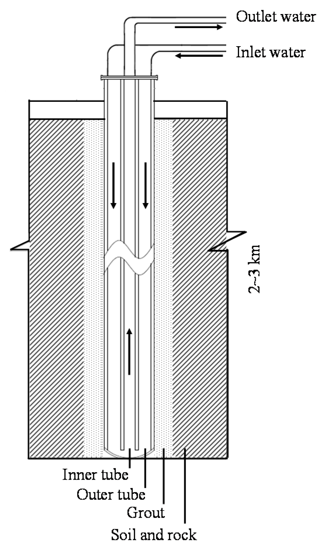
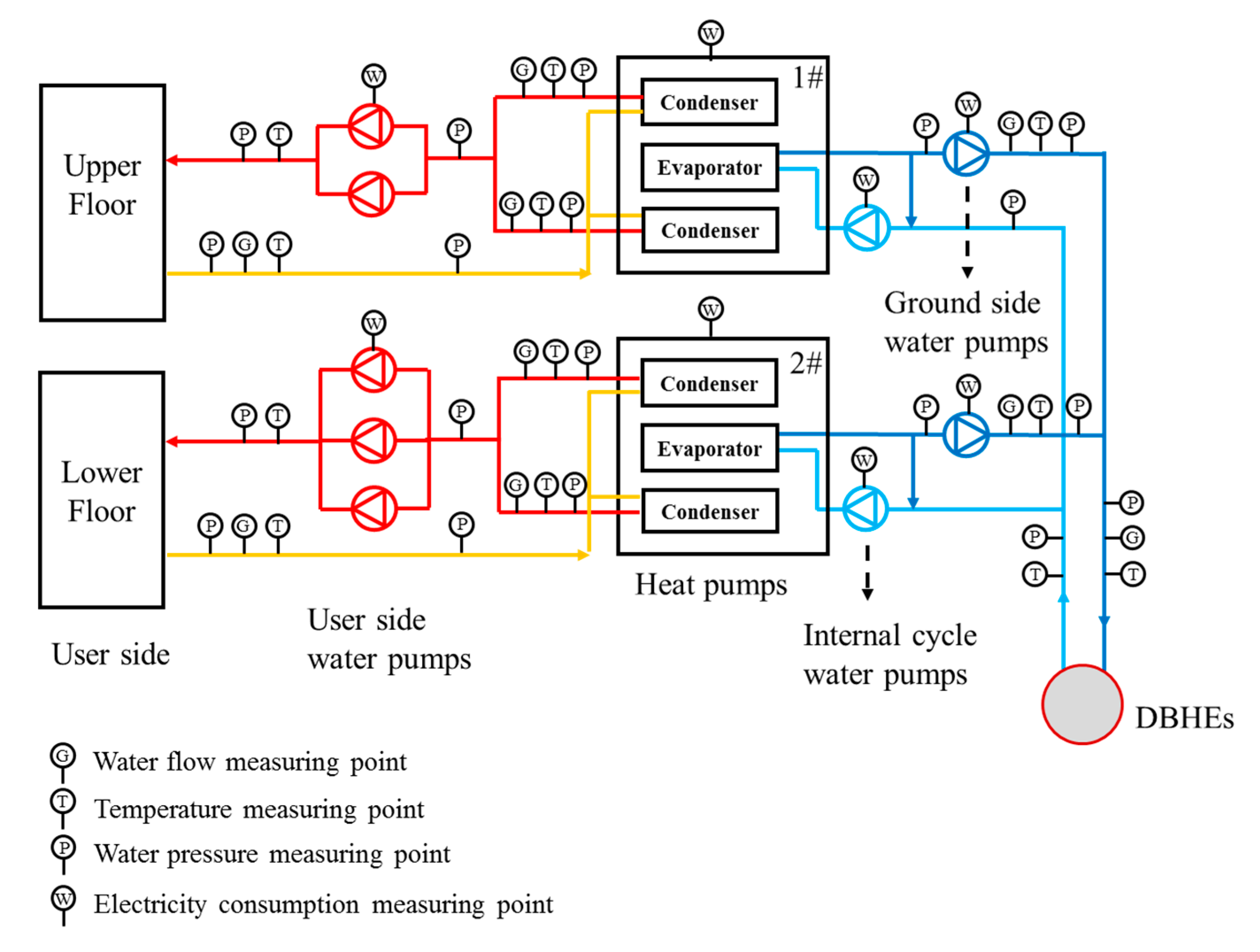
2.1. System Description

The medium-depth geothermal heat pumps system (MD-GHPs) under study is applied for the residential buildings in Xi’an, northern China and Table 1 lists the basic information. Figure 1 then shows the system diagram and measuring points. The MD-GHPs consist of the indoor heating systems, heat pumps, water distribution systems both in user side and ground side and 8 DBHEs with depth of 2500 m operating in parallel to extract heat from medium-depth geothermal energy. Among the two heat pumps, 1# heat pump is applied for upper floor with heat capacity of 2180 kW and 2# heat pump is applied for lower floor with heat capacity of 3500 kW. The field test lasts from November 15th 2017 to March 15st 2018 with the sample interval of 10 min. Where the water temperature, water flow rate of user side and ground side, as well as the electricity consumption of each devices are monitored.
As shown in Figure 2, the DBHE consists of inner pipe with materials of HDPE and outer pipe with materials of stainless steel. Then with backfill materials filled in the borehole. Table 2 then list the physical dimension and thermo-physical property of those materials. During the operation, ground-side water is pumped down to the DBHE through the outer pipe, extracting heat from ground. Then it flows upward through the inner pipe, meanwhile the heat is transferred to water in the outer pipe since the thermal resistance of the inner pipe is not high enough [13].

2.2. Analysis of Local Geothermal Evaluation

The DBHE extracts heat from the medium-depth geothermal energy, which is the main difference from the shallow-depth geothermal heat pump systems. Therefore, it is necessary to make clear the source and heat transfer process of the medium-depth geothermal energy, thus this kind of heat source can be fully understood.
Previous research [30] showed that the decay of radioactive elements in the core of earth (such as uranium 238, uranium 235, thorium 232 and potassium 40, etc.) produce approximately 9.5 × 10²⁰ J of heat per year and the heat mainly dissipates through the heat conduction of the crust. Thus the average ground heat flux (qc) with depth of 1–3 km is measured about 60 mW/m2 [31]. Due to the existence of geothermal heat flux, the average geothermal gradient in the ground deeper than 100 m could reach about 3 °C/hm [31].
As for the geothermal condition in Xi’an, the local heat flux is measured to be 75 mW/m2 [32] and the geothermal gradient is measured to be 2.8–3.5 °C/hm [33]. Besides, according to the well completion report [34], the geological stratifications of rock–soil in the region of 3000 m underground are made up of four main layers, Table 3 then lists the thermophysical parameters of different layers.

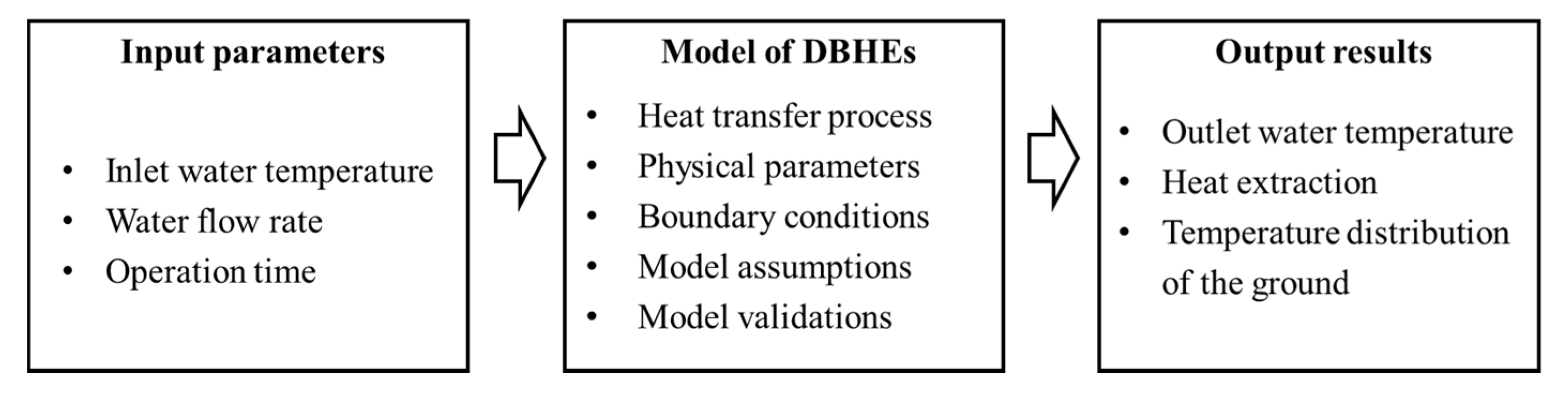
2.3. Methodology of Simulation Analysis

In order to examine the key factors of the heat transfer performance as well as analyze the feasibility and stability of DBHEs under long-term operation, a numerical simulation is developed. As shown in Figure 3, the model consists of model assumptions, mathematical equations of heat transfer process, physical parameters, boundary conditions and model validations. The Input parameters are the inlet water temperature, water flow rate and the operation time while the output results are outlet water temperature, total heat extraction and temperature distribution.

2.3.1. Model Assumption

As shown in Figure 2, the heat transfer process can be described as a two-dimensional cylindrical coordinate transient heat transfer process, including the heat convection between inner pipe fluid and outer pipe fluid, the heat convection between outer pipe fluid and outer pipe, the heat conduction in the outer pipe wall, the backfill material and the ground. The following assumptions are made to develop the heat transfer model.
(1)
According to previous studies [27,28,29], the fluctuation of ground surface temperature has little influence on the thermal performance of DHBEs. Thus the surface temperature is set as 13.0 °C, which is the annual average ambient temperature of Xi’an. Then the temperature of the ground rises with the depth following a linear relation with the local geothermal gradient of 2.85 °C/hm.
(2)
The thermal properties of DBHE (listed in Table 2) and of ground (listed in Table 3) are applied and assumed to be constant.
(3)
The composition of the soil and rocks are so complex to describe, thus four different layer (listed in Table 3) are applied to represent for the convenience of the simulation. Besides, as studied in previous research [35], the pure heat conduction model for the rock and soil surrounding the DBHE has the similar accuracy of the porous medium heat transfer mode. Therefore, the ground is assumed to be continuity media and only the heat conduction occurred in the ground. In addition, the contact thermal resistance (Rc) between DBHEs and grout is raised to reflect the effect of advection caused by underground water and other complex geothermal conditions. Then the value of Rc is adjusted to improve the accuracy of the model compared with field test results.

2.3.2. Mathematical Description of Heat Transfer Process

In this paper, the FVM with cylindrical coordinate is applied to describe the heat transfer process between DBHE and ground.
(1)
For the inner pipe fluid, since the fluid flows from the bottom to the top of DBHEs and the temperature of inner pipe fluid is higher than that of the outer pipe fluid, the heat is transferred from the inner pipe fluid to the outer pipe fluid with Equation (1)
T f , i n τ + ( u i n T f , i n ) z = K i ( T f , o T f , i n ) ρ f C f A i n
where T f , i n and T f , o are the temperature of inner and outer pipe fluid, u i n is the flow velocity of inner pipe fluid, ρ f is the density of inner pipe fluid, C f is the heat capacity of inner pipe fluid,   A i n is the cross-section area of inner pipe with A i n = π r i i 2 , r i i is the inner surface radius of inner pipe.   τ is the time parameter, z is the depth direction parameter and r is the radius direction parameter. K i is the equivalent thermal conductivity of the unit length of the inner pipe, which is calculated with Equation (2)
K i = π / ( 1 2 h 1 r i i + 1 2 λ i n ln r i o r i i + 1 2 h 2 r i o )
where r i o is the outer surface radius of inner pipe, λ i n is the thermal conductivity of the inner pipe. h 1 , h 2 are the convective heat transfer coefficients of the inner surface and outer surface of inner pipe. The values of h 1 , h 2 could be calculated with Equations (3)–(6) [35].
h 1 = N u , i i λ f 2 r i i
h 2 = N u , i o λ f d o
N u , i i = 0.023 R e , i i 0.80   P r 0.40
N u , i o = 0.018 R e , i o 0.82   P r 0.52
where λ f is the thermal conductivity of the water, N u , i i and N u , i o are Nusselt number of inner surface and outer surface of inner pipe.   R e , i i and R e , i o are Reynolds numbers of inner surface and outer surface of inner pipe. P r is Prandtl number of water, which is set as 6.22 according to the water temperature. d o is the hydraulic diameter of outer pipe in m, which can be calculated with Equation (7).
d o = 4 A o f
where d o equivalent meter of outer pipe, A o is the cross-section area of outer pipe with A o = π ( r o i 2 r i o 2 ) , f is the wetted perimeter of outer pipe with f = 2 π ( r o i + r i o ) , r o i is the inner surface radius of outer pipe.
(2)
For the outer pipe fluid, the heat transfer process can be described with Equation (8)
T f , o τ + ( u o T f , o ) z = K i ( T f , i n T f , o ) ρ f C f A o + K o ( T g r o u t T f , o ) ρ f C f A o
where u o is the flow velocity of outer pipe fluid, Tgrout is the temperature of grout surrounding the DBHE. K o is the equivalent thermal conductivity of the unit length of the outer pipe, which is calculated with Equation (9)
K o = π / ( 1 2 h 3 r o i + 1 2 λ o ln r o o r o i + R c )
where r o o is the outer surface radius of outer pipe, λ o is the thermal conductivity of the outer pipe wall, R c is the contact thermal resistance between DBHEs and grout, h 3 is the convective heat transfer coefficients of the inner surface inner pipe, which could be calculated with Equations (10) and (11) [35].
h 3 = N u , o i λ f d o
N u , o i = 0.016 R e , o i 0.82   P r 0.52
where N u , o i and R e , o i is Nusselt number and Reynolds numbers of inner surface of outer pipe.
(3)
For backfill material and the ground, the heat transferred by heat conduction in the same form. Taking the ground for example, the process can be described with Equation (12)
ρ g C g T g τ = 1 r r ( r λ g T g r ) + z ( λ g T g z ) ,
where Tg is the ground temperature, ρ g is the ground density, C g is the ground heat capacity, λ g is the ground thermal conductivity.

2.3.3. Discretization of the Mathematical Description

Figure 4 shows the meshes discretized in depth direction (z) and radius direction (r). where r 4 and r g o are the radius of the center and boundary of grout. r 5 r N are the radius of the ground with Equation (13). Where k is the constant coefficient. Besides, Δ z is the depth of each mesh. The value of k and Δ z will be discussed later.
r i = r g o k i 10
Taking the transient heat transfer process in ground with coordinate (i,j) for example, the equation could be represented as (14)–(19) after discretizing meshes,
A ( i , j ) T ( i , j , τ ) -   A ( i 1 , j ) T ( i 1 , j , τ ) -   A ( i + 1 , j ) T ( i + 1 , j , τ ) -   A ( i , j 1 ) T ( i , j 1 , τ ) -   A ( i , j + 1 ) T ( i , j + 1 , τ ) =   B ( i , j ) T ( i , j , τ 1 )
A ( i , j ) = A ( i + 1 , j ) + A ( i 1 , j ) + A ( i , j + 1 ) +   A ( i , j 1 ) + B ( i , j )
A ( i 1 , j ) = π ( r i + r i 1 ) Δ z λ g r i r i 1
A ( i + 1 , j ) = π ( r i + r i + 1 ) Δ z λ g r i + 1 r i
A ( i , j 1 ) = A ( i , j + 1 ) = π A i j λ g Δ z
B ( i , j ) = A i j Δ z ρ g C g Δ τ
where A i j is the cross-section area of ground (i,j) with A i j = π ( ( r i + r i + 1 ) 2 ( r i + r i 1 ) 2 ) / 4 .

2.3.4. Boundary Conditions and Initial Condition

(1)
The boundary condition at the surface of the ground is set as isothermal boundary with temperature of 13.0 °C, which is the annual average ambient temperature of Xi’an.
(2)
The boundary condition at the bottom of the ground, as mentioned above, should be set as constant heat flux condition with Equation (20)
λ g T g z | z = H b = q c
where H b is the depth of bottom boundary, q c is local ground heat flux, which is measured to be 75 mW/m2.
(3)
Boundary conditions at the bottom of the DBHEs can be described with Equation (21)
T f , i n = T f , o  
(4)
As for the radial far boundary, since more than 1 DHBE operate in parallel in practical projects and the ground between 2 DBHEs is influenced by both DBHEs, thus the temperature fails to remain constant. Hence, the adiabatic boundary is preferable for the radial far boundary.
(5)
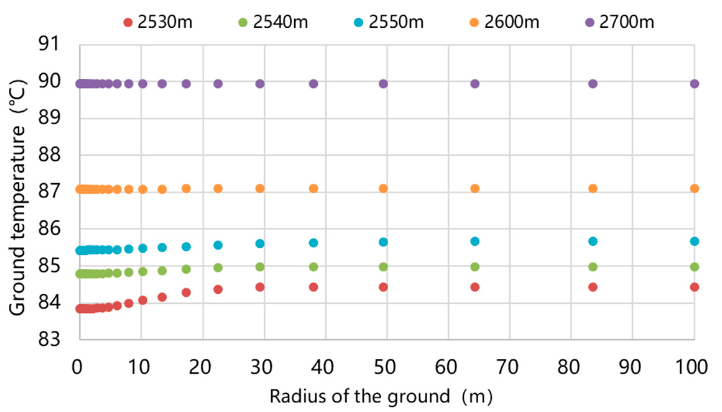
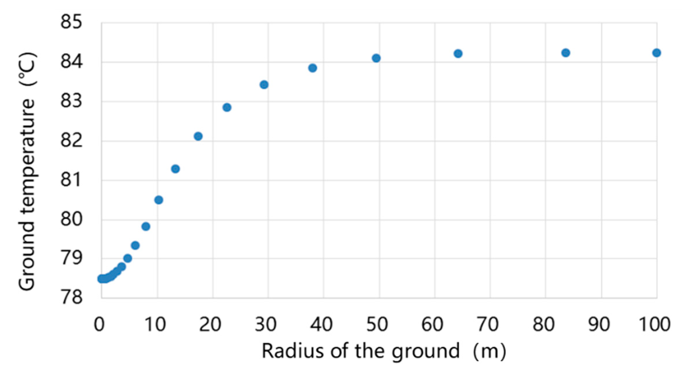
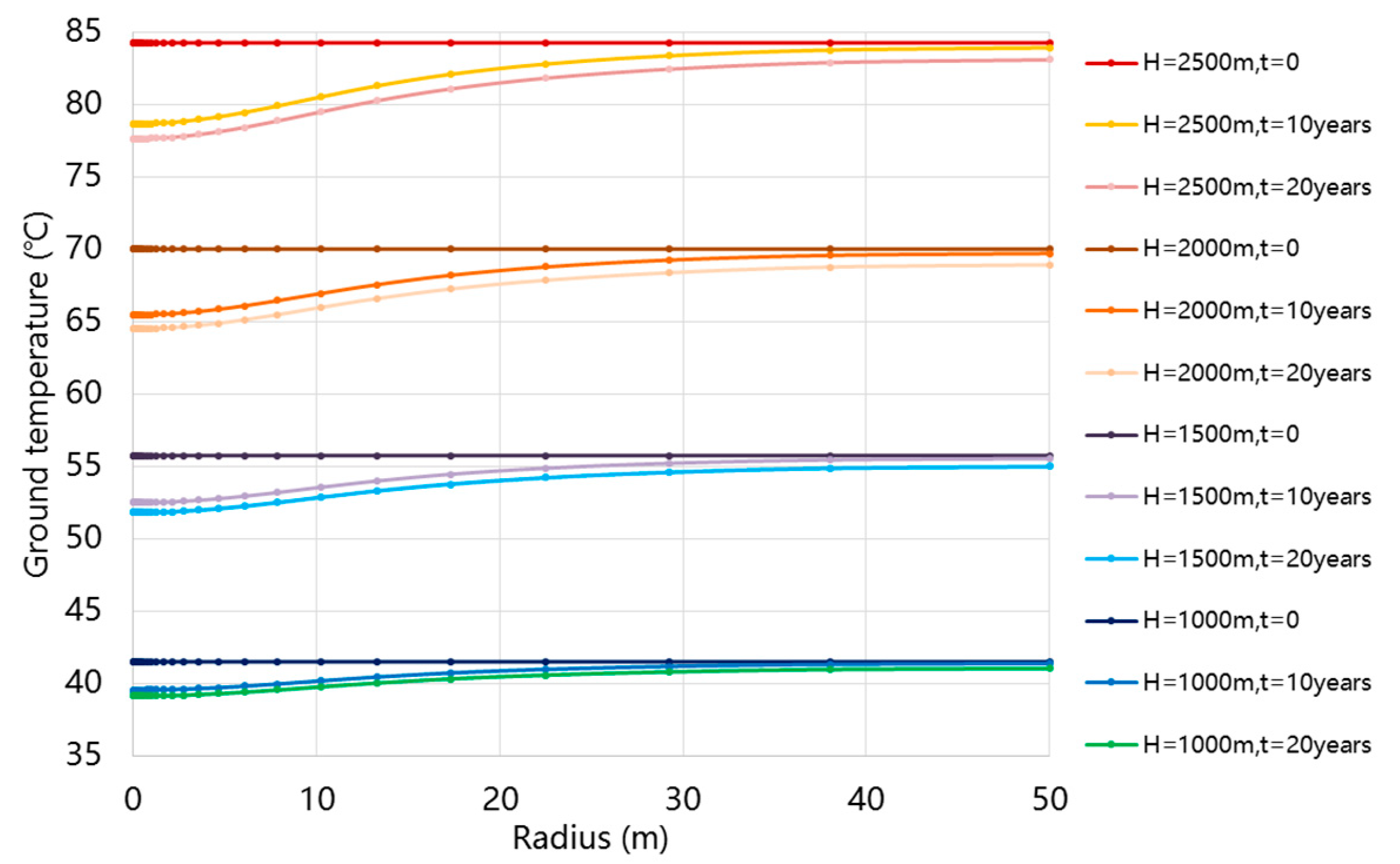
To confirm the specific depth of the bottom boundary and radius of the radial far boundary, a simulation of 10-years operation is conducted. In the simulation, the depth of the bottom boundary is set as 3000 m and the radius of the radial far boundary is set as 100 m. Figure 5 depicts the ground temperature distribution at the depth of 2530–2700 m. It shows that the ground temperature remains the same along the radial direction at the depth of 2700 m. Therefore, the depth of bottom boundary is then re-set at 2700 m.
Figure 6 shows the ground temperature distribution in radius direction at 2500 m after 10-years operation. Results indicate that the ground temperature with radius of 50 m is only 0.13 K lower than the ground temperature with radius of 100 m. Therefore, the radius of the radial far boundary is then re-set at 50 m.
(6)
The initial ground temperature can be calculated with Equation (22)
T g = T g , 0 + 2.85 100 z
where T g , 0 is the ground surface temperature with the value of 13.0 °C in Xi’an, z is the depth of the ground.
After getting the coefficient matrix of the heat transfer process, the transient temperature distribution could be solved by tridiagonal matrix algorithm in Matlab. Thus the transient temperature distribution in each time could be obtained.

2.3.5. Analysis on the Mesh Independence

In order to analyze the mesh independence of p, ∆z and time step ∆τ, the simulation with 1-year operation is conducted. Besides, the p, ∆z, ∆τ are set as 1.1, 1 m and 60 s in base case. Table 4 shows the outlet water temperature at the end of 1 year with different p, ∆z andτ.
According to the analysis, the p of 1.3, ∆z of 5 m and ∆τ of 3600 s are chosen as set values in the simulation, thus the simulation time could be saved when attaining relevantly accurate results.

2.3.6. Model Validation

In order to check the accuracy of the model, the field test is conducted to obtain the operational data. Figure 7 then presents the field test results from 21st November to 18th December As mentioned above, 1# heat pump and 2# heat pump operate with the same heat source. However, during the operation, the heating demand in upper floor is lower than rated value with low occupancy rate, thus 1# heat pump starts and stops frequently with ground side water pump operating continuously, while 2# heat pump operates continuously. Consequently, the inlet water temperature of DBHEs rises when 1# heat pump turns off, then drops when 1# heat pump turns on, showing two different lines. Besides, when the 1# heat pump turns off for a long time, the ground side water pump would also turn off, then the flow rate of ground side drops rapidly, which also shows two different lines. With those variable operating conditions, the inlet water temperature varies from 20 °C to 34 °C and flow rate varies from 10 m3/h to 23 m3/h. Then we can see that the outlet water temperature declines from 37 °C to 30 °C and also fluctuates with the changing of inlet water temperature and flow rate. From 18th Dec to 21st Dec, the DBHE turns off then turns on again. During the turning-off period of 84 h, the ground side water continues to extract heat from the ground thus the water temperature rises gradually. Then when the DBHE turns on again, the outlet water temperature reaches 45.1 °C and drops gradually with the operation of the systems.
This long-term operational data of DBHE contains a variety of different conditions with wide range of inlet water temperature and flow rate during continuous operation and also contains data during intermittent operation. Thus this operational data could be applied to check the dynamic response capability of the model. Then the field test flow rate and inlet water temperature are input to the model to calculate the outlet water temperature, with R c setting as 0.01. Results are presented in Figure 8.
The relative error ( δ ) is calculated with Equation (23)
δ = T o , s T o , f T o , f , m a x T o , f , m i n
where T o , s is the simulation outlet water temperature, T o , f is the field test outlet water temperature. T o , f , m a x and T o , f , m i n are the maximum and minimum of field test outlet water temperature to reflect the amplitude of the values during the field test, which are measured to be 45.1 °C and 22.6 °C.
It can be seen that the simulation values nearly equal to the field test results for this transient operation mode with relative errors between −10–10%, showing that the model is accurate enough to analyze the heat transfer process of DBHEs.

3. Results and Discussion

After confirming the accuracy of numerical simulation, the model can be used to analyze the heat transfer process of the DBHEs. Besides, the influence factors are analyzed for the guidance of the system design and the optimization of control strategies during the heating season. Furthermore, the variation of ground temperature and the heat transfer performance under long-term operation are described. Thus the feasibility and stability of the DBHEs can be proved.

3.1. Heat Transfer Performance of DBHEs in Continuous Operation in a Heating Season

With the simulation, the continuous heat transfer performance of the DBHEs can be calculated and analyzed. Figure 9 shows the outlet water temperature, inlet water temperature and heat extraction among the heating season. With the inlet water temperature set at 20 °C and flow rate set at 6 kg/s, the outlet water temperature reaches 44.6 °C and the heat extraction reaches 619 kW at the beginning. Then with the operation of the system, the ground temperature declines gradually, thus leading to the declining of the outlet water temperature and the heat extraction. During the whole heating season, the average outlet water temperature reaches 30.4 °C and the heat extraction reaches 263.0 kW. Besides, the total heat extraction reaches 2727 GJ for one DBHE, which is higher than that of the conventional shallow-depth heat exchangers.

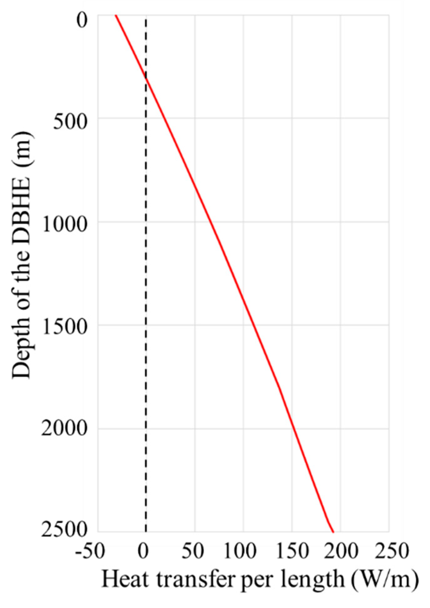
3.2. Analysis of the Heat Transfer Process in the DBHEs

In this part, a transient operation condition at the end of heating season (120 days later from the beginning) is taken to analyze the heat transfer process in the DBHEs, where the inlet water temperature of the DBHEs is 20.0 °C, the flow rate is 6.0 kg/s and the outlet water temperature is calculated to be 29.7 °C. Figure 10 depicts the temperature distribution in DBHE.
When pumped down to the DBHE through the outer pipe, the water extracts heat from the ground and also from the water in the inner pipe since the thermal resistance of the inner pipe wall is not high enough. Its temperature rises from 20.0 °C to 41.0 °C at the bottom of the DBHE. Then it flows upward through the inner pipe; with the heat being transferred to the outer pipe water, its temperature declines to 29.7 °C, almost 11.3 K lower than that at the bottom. Though the heat is not lost to the ground, it increases the temperature of the outer pipe water, thus reducing the heat extracted from the ground. Besides, the performance of the heat pump declines with the decreasing of outlet water temperature. Therefore, the insulation of the inner pipe should be enhanced to reduce the heat loss. In the meantime, heat transfer performance of the outer pipe should be enhanced to extract more heat from the ground.
Figure 11 shows the heat transfer per unit length along the DBHE, with the increasing depth, the temperature of the ground rises, leading to the increasing of the heat transfer per unit length. The value reaches 193 W/m at the bottom of the DBHE with average value of 97.8 W/m. However, at the ground with a depth shallower than 300 m, the temperature of the outer pipe water is higher than that of ground, thus the heat is transferred from the outer pipe water to the ground. Therefore, for the optimization of outer pipe, more works should be done to enhance the heat transfer performance in deep part but for the shallow part, the insulation performance should be enhanced instead to decrease the heat loss.

3.3. Analysis on the Influence Factors of Heat Transfer Performance

In order to optimize the system design and control strategies of DBHEs, the influence factors of heat transfer performance should be analyzed and studied. As shown in Figure 12, the influence factors could be classified into 3 categories: (1) External factors for the geothermal properties, including thermal conductivity of ground and geothermal gradient;( 2) Internal factors for the DBHEs, including the thermal property and depth of DBHEs; (3) Synergic adjustment for operation during the heating season, including the adjustment of inlet water temperature and flow rate, which are field tested to be key factor influencing the heat transfer performance of DBHEs [13].

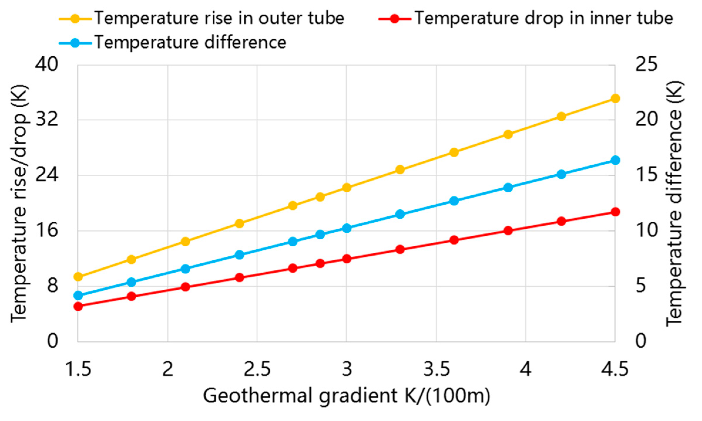
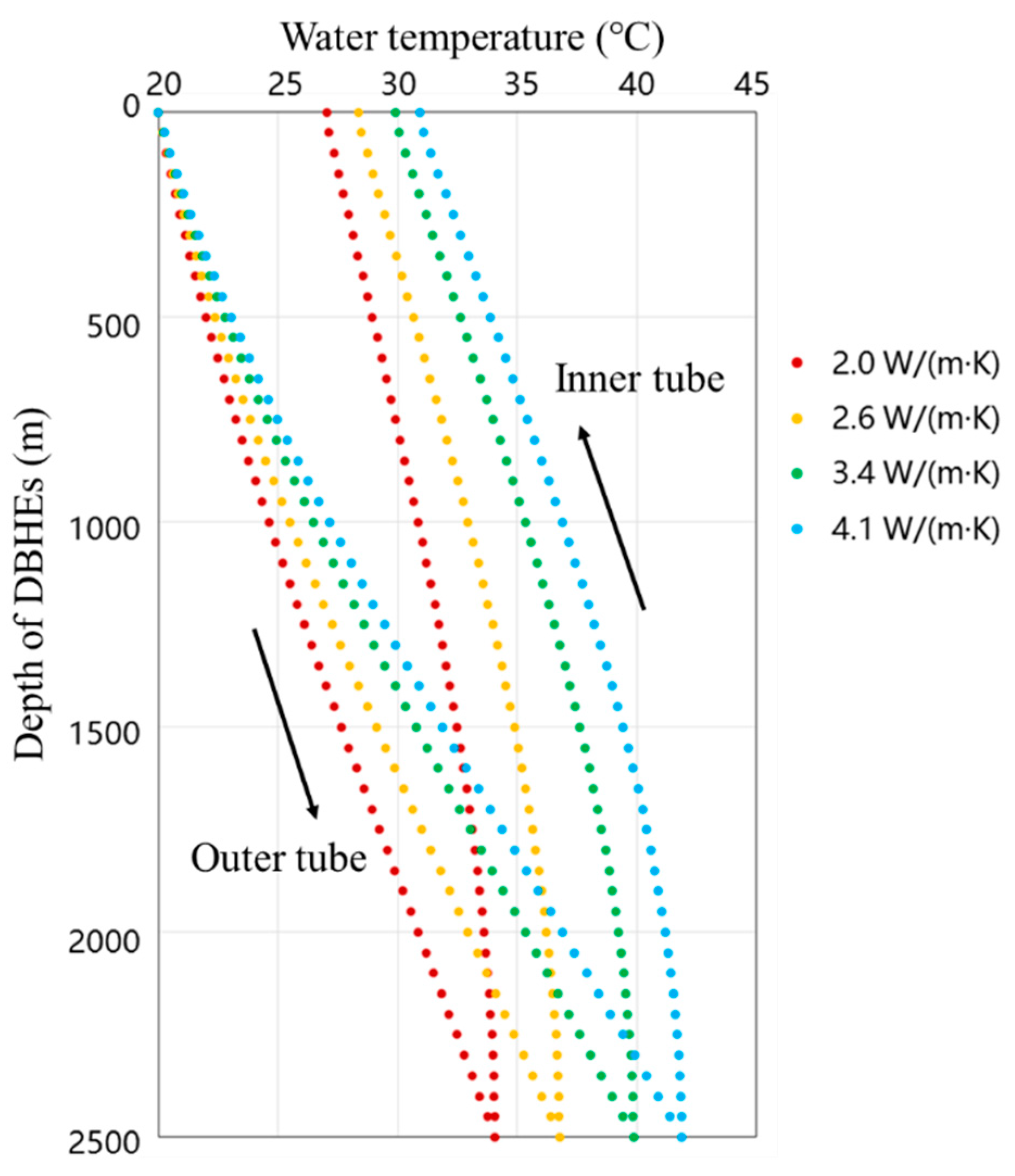
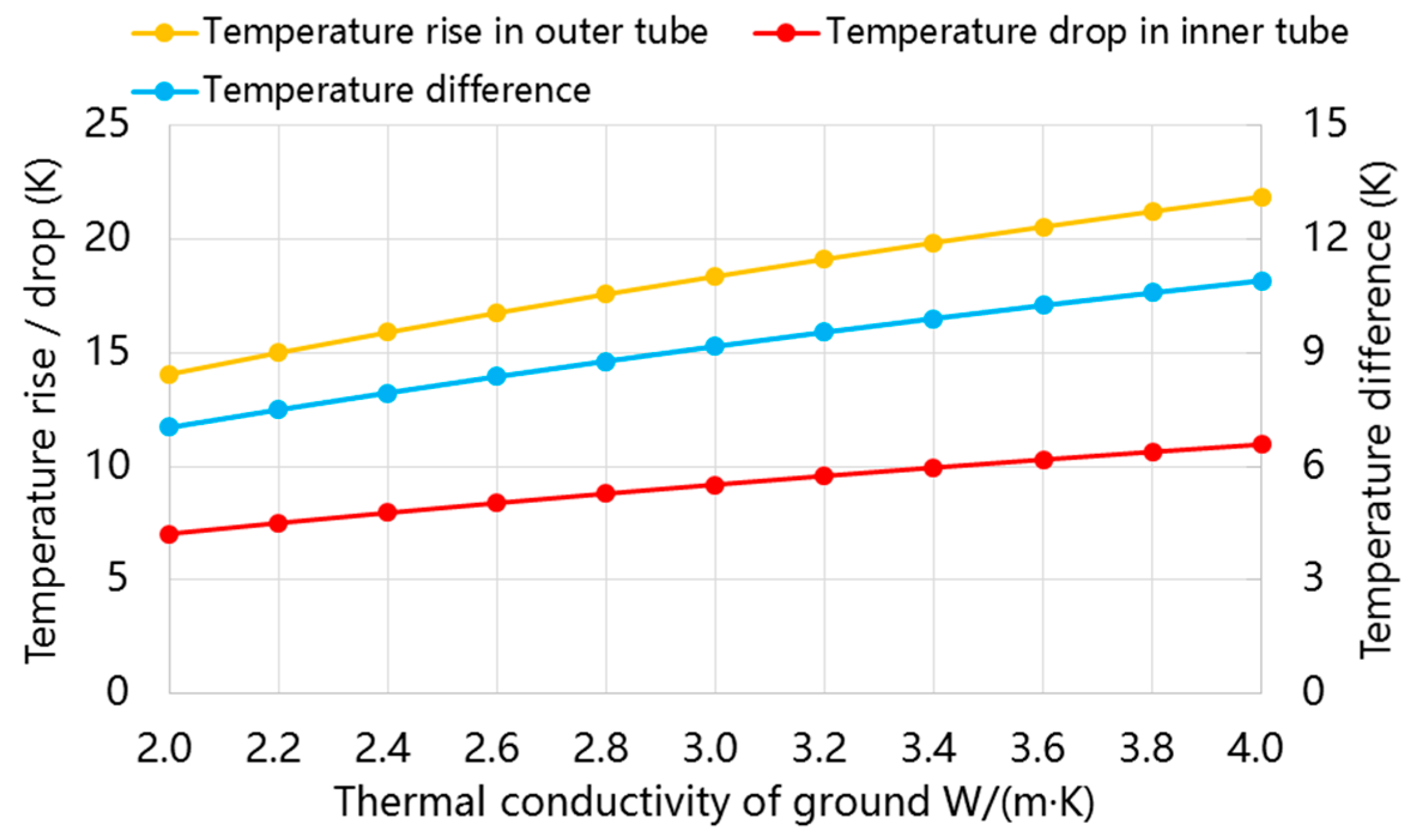
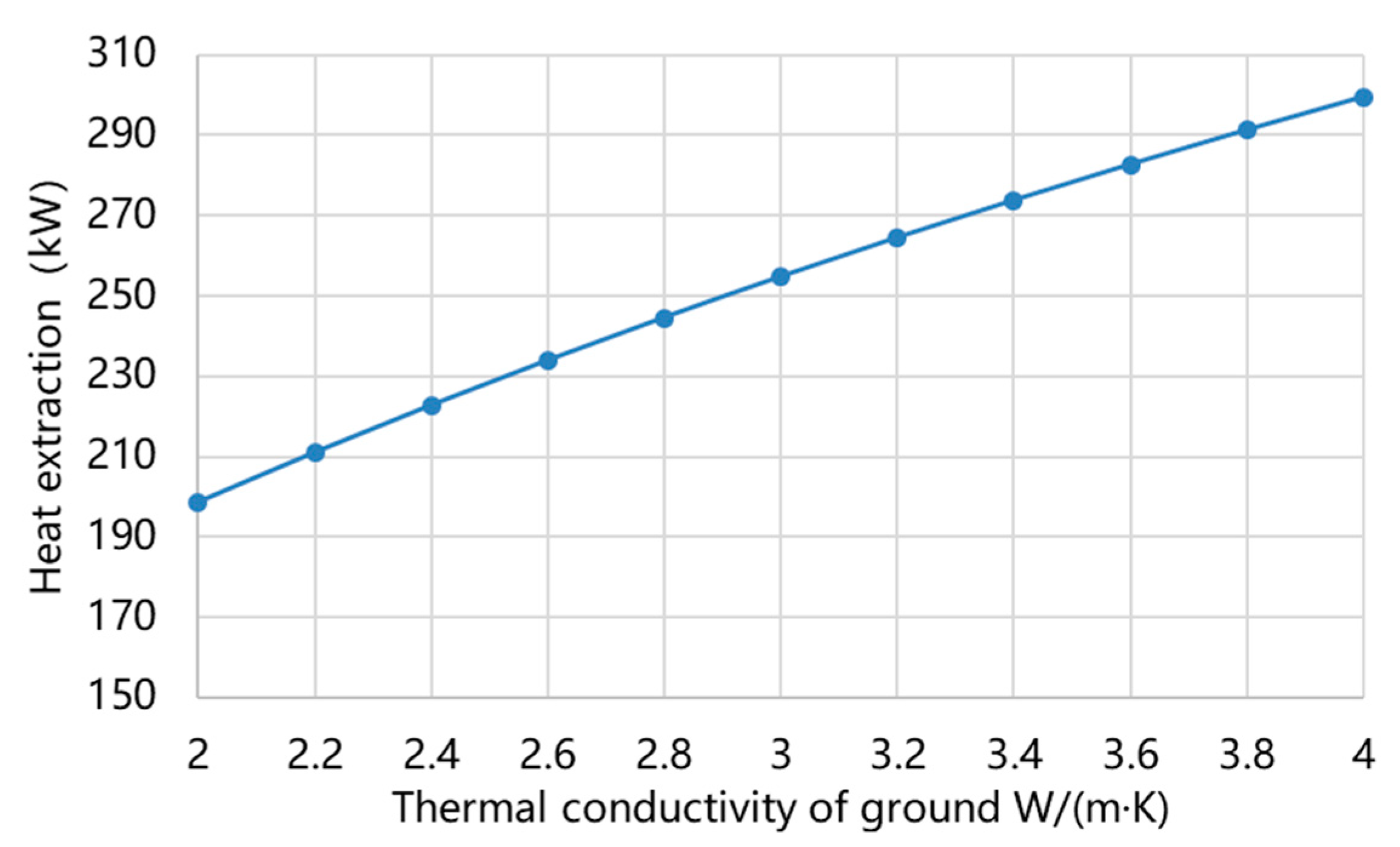
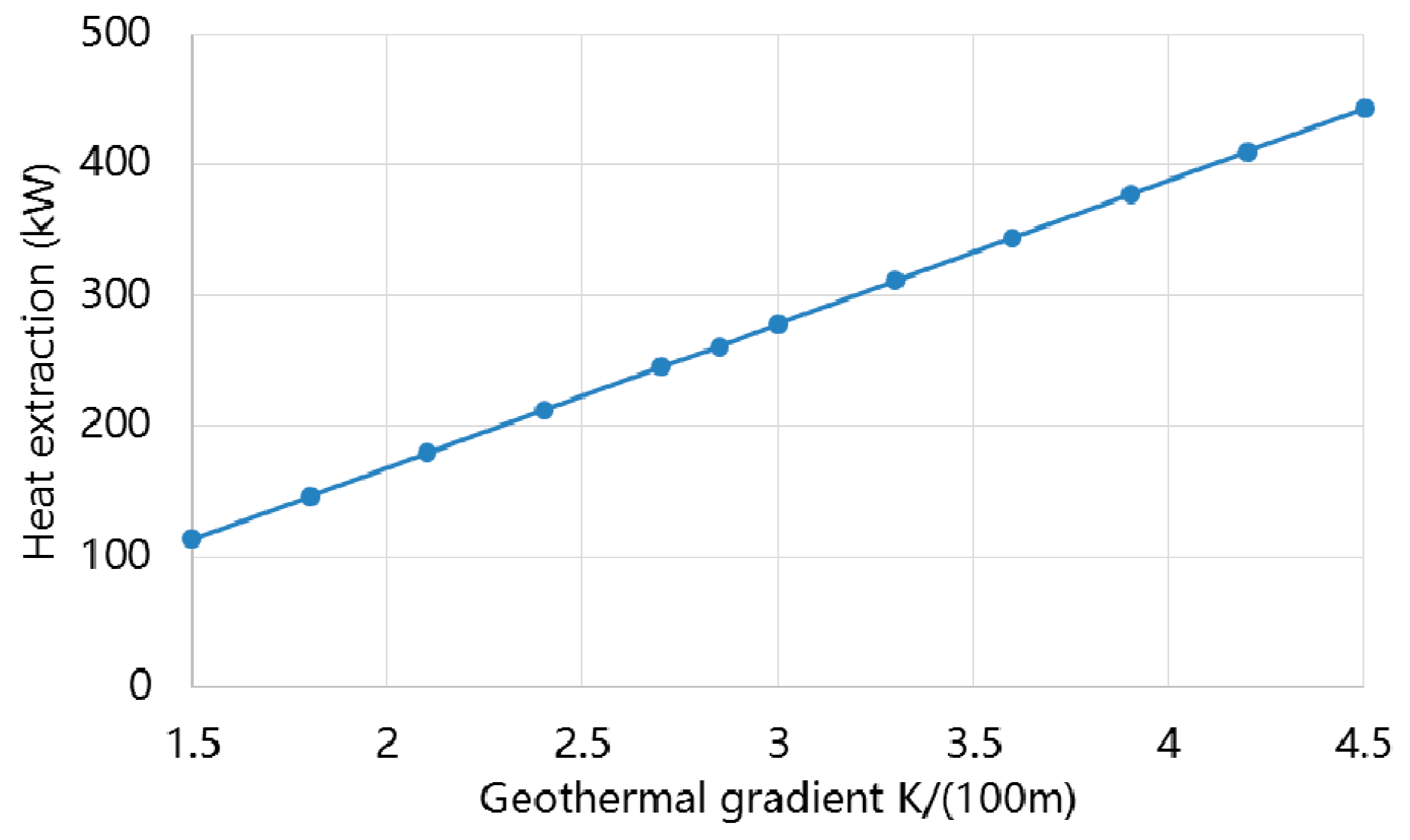
3.3.1. Effect of Geothermal Properties on the Heat Transfer Performance

In this section, the effect of ground thermal conductivity and geothermal gradient on the heat transfer performance of the DBHEs are examined.
With the inlet water temperature set as 20 °C and the flow rate set as 6 kg/s, Figure 13 shows the water temperature distribution in DBHEs at the end of heating season under different ground thermal conductivity. It can be seen that with the increasing of ground thermal conductivity, the heat transfer between outer pipe water and the ground is enhanced, thus the temperature rise of outer pipe water increases obviously. However, the temperature difference between inner pipe water and outer pipe water increases at the same time, thus more heat is lost from inner pipe water to the outer pipe water, leading to increasing of temperature drops of inner pipe water. As shown in Figure 14, since the outer pipe water temperature rises more than the water temperature drops in the inner pipe, the temperature difference between outlet water and inlet water increases, leading to the increasing of average heat extraction during the heating season (Figure 15).
As for the geothermal gradient, Figure 16 presents its effect on the water temperature difference. Also, with the inlet water temperature set as 20 °C and the flow rate set as 6 kg/s, it can be seen that with the increasing of geothermal gradient, the ground temperature increases, thus the temperature difference between outer pipe water and the ground increases, therefore, the heat transferred from ground to the outer pipe water increases, leading to the increasing of water temperature rise in outer pipe. Also since the outer pipe water temperature rises more than the water temperature drops in the inner pipe, the temperature difference between outlet water and inlet water increases, leading to the increasing of average heat extraction during the heating season (Figure 17).
Consequently, the ground thermal conductivity and geothermal gradient have a significant influence on the heat transfer performance of DBHEs. These two index reflect local geothermal properties and can be regarded as external factors. Before the construction of DBHEs, the geothermal properties should be investigated and analyzed to guide the system design of DBHEs.

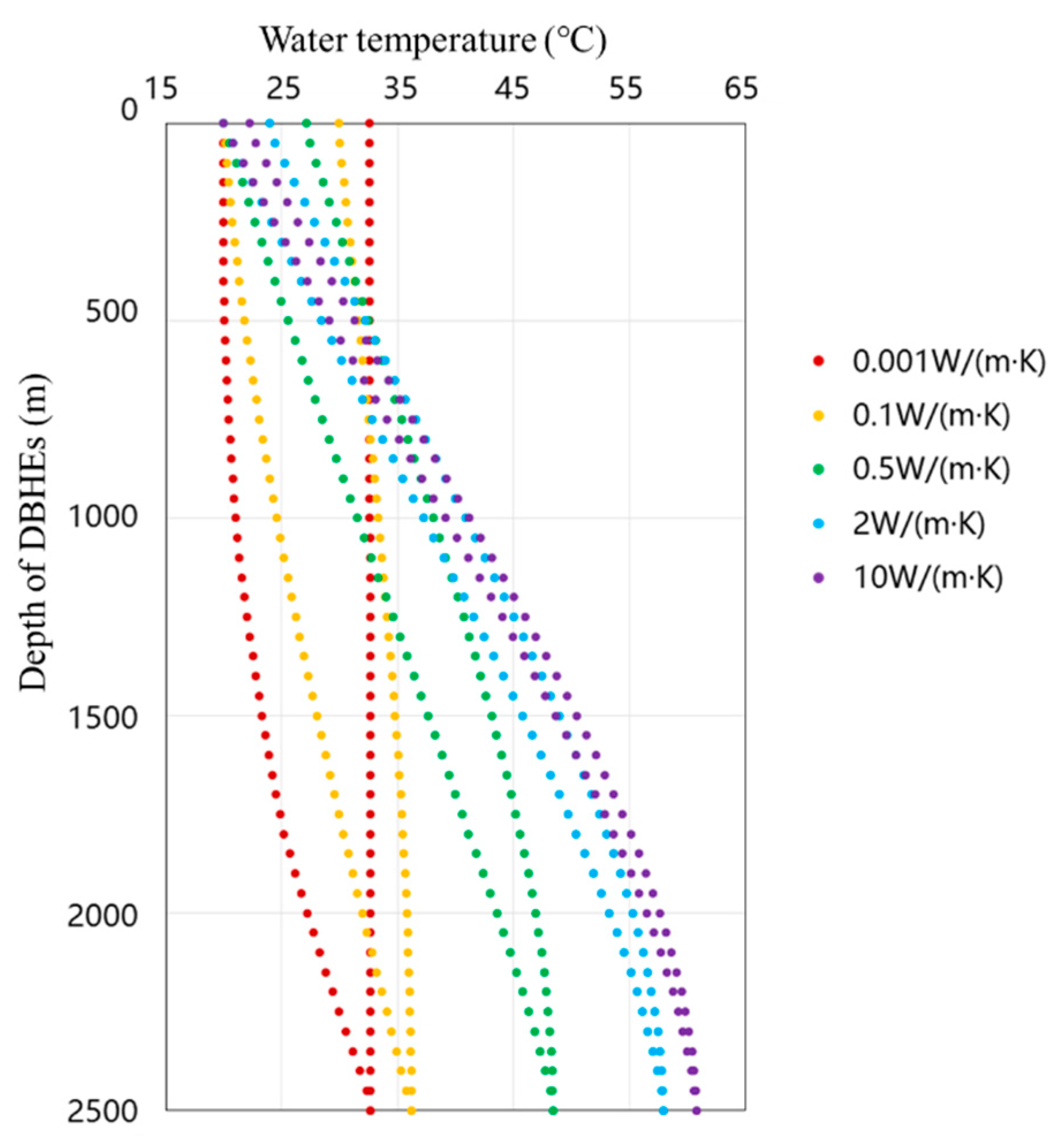
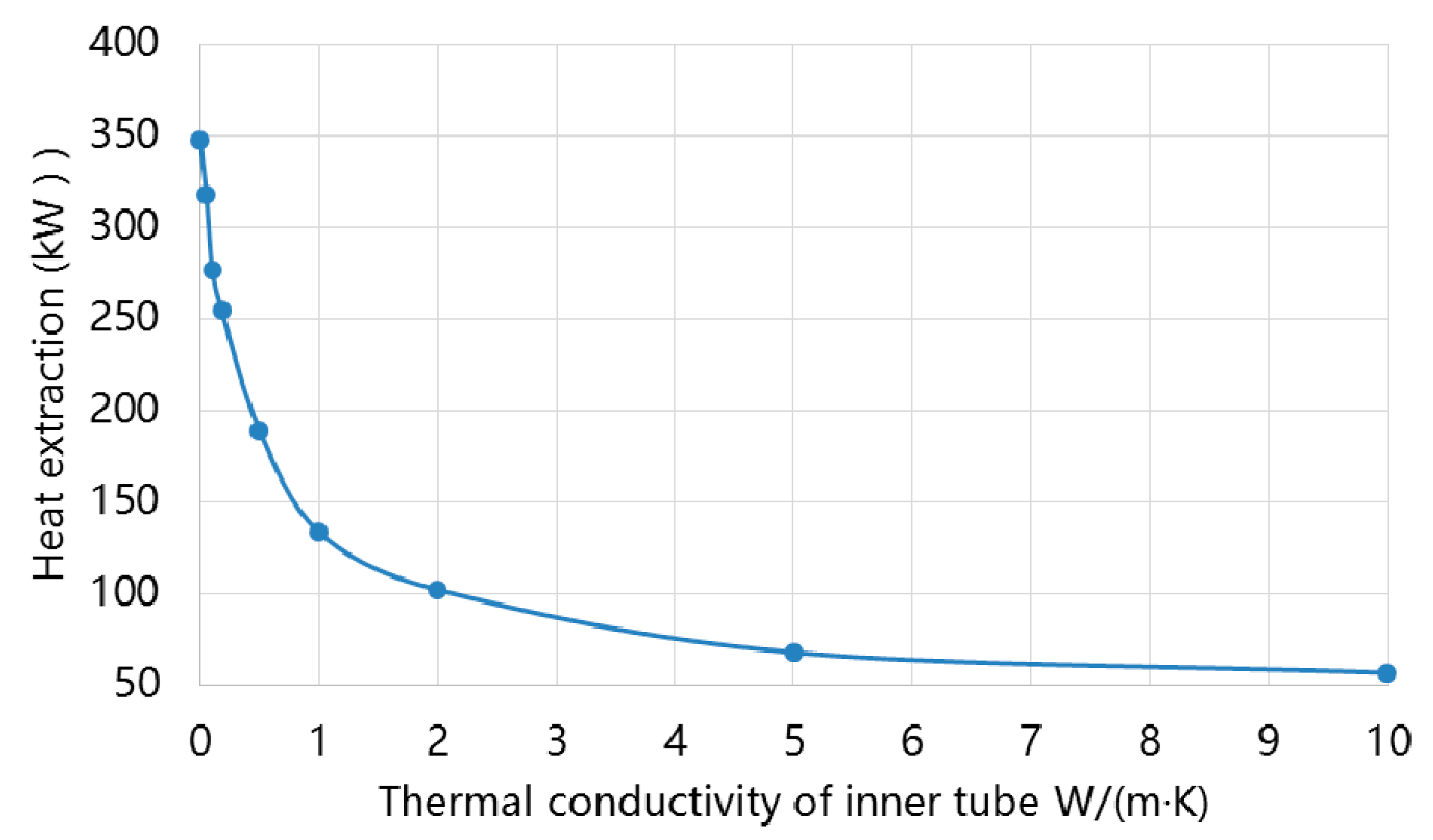
3.3.2. Effect of Thermal Conductivity of Inner Pipe

Apart from the external factor, the thermal properties and size of DBHEs, so called internal factors, also have obvious influence on the heat transfer performance of DBHEs. As mentioned above, when the water flows upward through the inner pipe, its temperature declines since the thermal resistance of the inner pipe wall is not high enough. Figure 18 shows the water temperature distribution in DBHEs at the end of heating season under different thermal conductivity of inner pipe, it can be seen that with the increasing of thermal conductivity of inner pipe, more heat is transferred from inner pipe water to the outer pipe water, leading to the increasing of water temperature rise in outer pipe. However, as shown in Figure 19, with the increasing of outer pipe water temperature, the temperature difference between the outer pipe water and the ground decreases. Consequently, the heat extracted from the ground decreases, then the average heat extraction during the heating season decreases.
The insulation of the inner pipe should therefore be enhanced to reduce the heat transferred from the inner pipe water to the outer pipe water, thus the outlet water temperature and heat extraction could be increased. When the inner pipe reaches adiabatic, the heat extraction reaches the max value under current operation mode. Thus, the insulation of inner pipe is an important index to evaluate the design of the DBHEs.

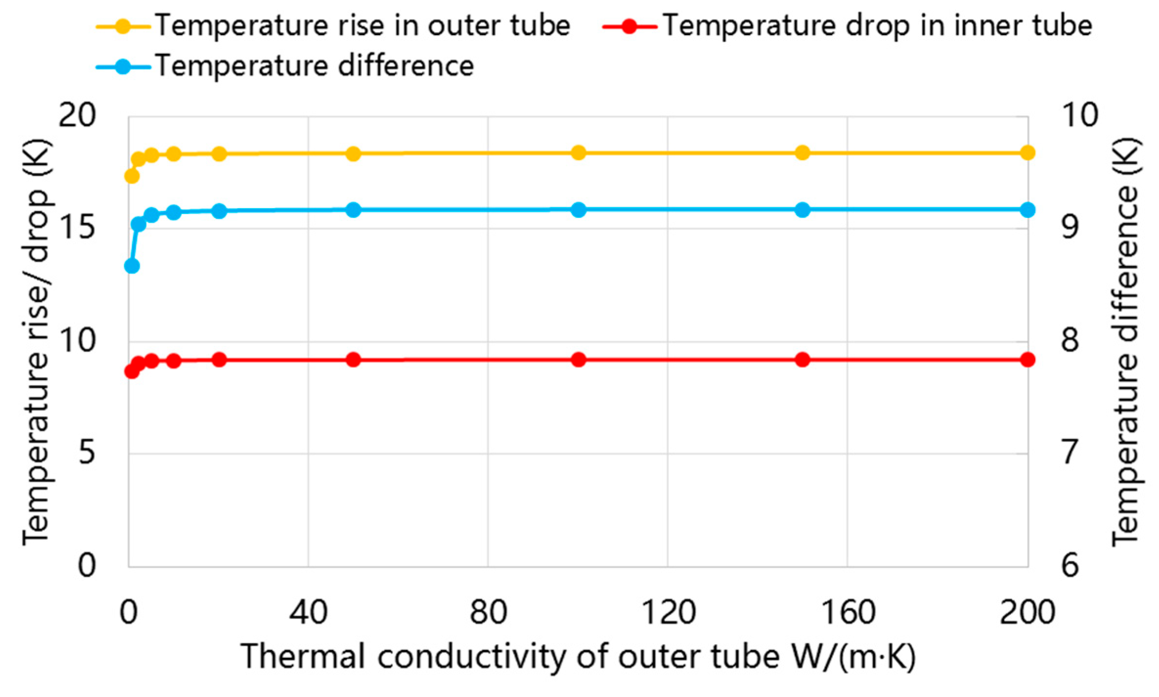
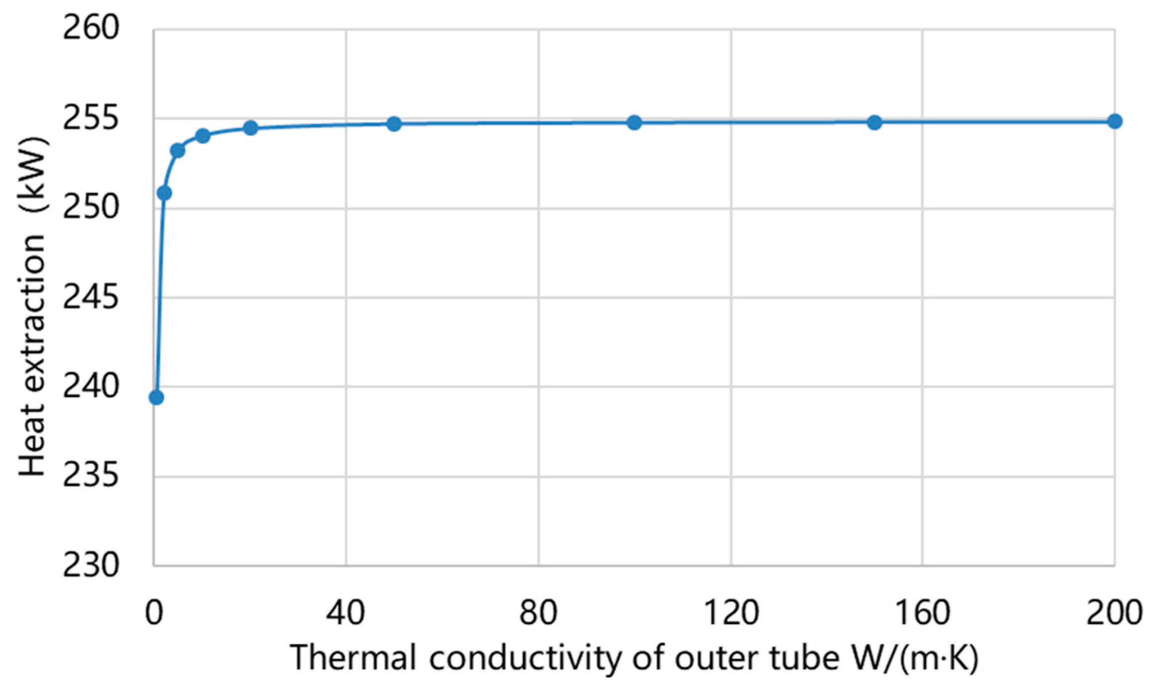
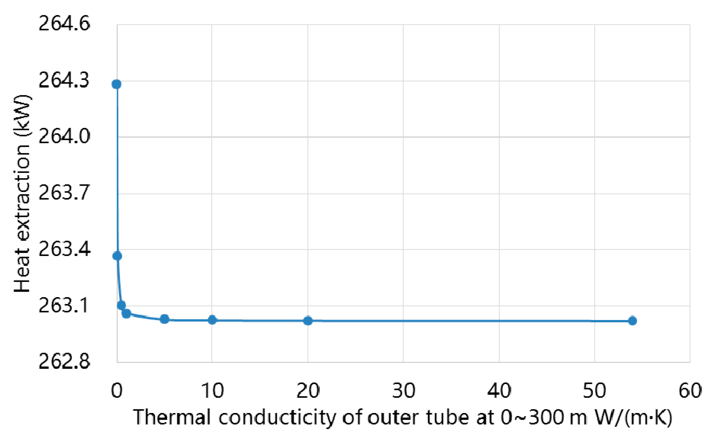
3.3.3. Effect of Heat Transfer Performance of Outer Pipe

The thermal conductivity of the outer pipe influences the heat transfer from the ground to the outer pipe water. Figure 20 and Figure 21 depict the calculated results. However, among the heat transfer process between outer pipe water and the ground, the thermal resistance of ground plays a dominant role, accounting for nearly 90% of the total thermal resistance, thus the thermal conductivity of outer pipe has little effect on heat transfer performance of DBHEs when the thermal conductivity of outer pipe reaches higher than 10 W/(m·K). In practical project, carbon steel is used as outer pipe with the thermal conductivity of 54 W/(m·K). Therefore, there is no need to improve the thermal conductivity of outer pipe in the optimization.
As mentioned above, since the outer pipe water temperature is higher than ground temperature at 0–300 m, the thermal conductivity of outer pipe at 0–300 m should be decreased to avoid heat loss. Then a simulation is conducted to analyze the effect of this optimization method. Results are shown in Figure 22.
It can be seen that this method has nearly no influence on the total heat extraction of DBHE. On the one hand, the temperature difference between ground and outer pipe water at 0–300 m is smaller than that at deeper place. Besides, during the operation, the ground at 0–300 m is warmed up gradually thus the temperature deference further decreases. On the other hand, since the thermal resistance of ground plays a dominant role, there is no need to change the thermal conductivity of outer pipe or use different materials at different depth.
Therefore, as for the optimization of outer pipe, attentions should be paid to increase the heat transfer area, where increasing the depth is a most straightforward method. Figure 23 shows the water temperature distribution in DBHEs at the end of heating season under different depth of DBHE. It can be seen that with the increase of depth, the ground temperature at the bottom increases at the same time, thus leading to obvious increasing of outer pipe water temperature. Though the water temperature drops in the inner pipe increases at the same time, the total effect is that the average heat extraction increases rapidly with the increase of the DBHEs depth (Figure 24).

3.3.4. Effect of Operation Parameters

Apart from the design parameters, the operational parameters—like inlet water temperature and flow rate—can be adjusted to meet the heat extraction demand. Figure 25 demonstrates the effect of inlet water temperature and flow rate on the average heat extraction during the heating season of DBHEs.
The abscissa shows the flow rate of DBHEs from 10 to 40 m3/h, the ordinate shows the inlet water temperature of DBHEs from 5 to 25 °C. The color scale represents the average heat extraction of DBHEs from 100 to 500 kW. According to the simulation results, it can be seen that the heat extraction increases with the decrease of inlet water temperature and increase of flow rate. When the inlet water temperature decreases and flow rate increases, the temperature difference between outer pipe water and the ground increases, thus the heat extraction will increase.
Therefore, at the beginning and ending of heating season with lower heating demand, the inlet water temperature of DBHEs can be increased and the flow rate can be decreased. Also, the supply water temperature in user side can be decreased, thus the energy efficiency of MD-GHPs can be improved. Then at the peak-load period, the inlet water temperature of DBHEs can be decreased and the flow rate can be increased to realize higher heat extraction from DBHEs to meet the higher heat demand for the system.

3.3.5. Empirical Equations Fittings of Influence Factors

As studied above, the heat transfer performance is greatly influenced by geothermal properties, design and operation parameters of DBHEs. In order to quantitatively reflect the effect of each factor, empirical equations were fitted from simulation results with Equations (24)–(28).
Taking the influence of λ g for example, the average Q during the heating season with λ g of 3.0 W/(m·K) is set as basic value then the changing ratio of Q with other values of λ g could be described with Equation (24)
R a t i o λ g = Q λ g Q λ t , 0 = g λ g 2 + h λ g + i
Then the average Q with geothermal gradient (D) of 3 °C/hm and the depth of DBHEs (HE) of 2500 m are respectively set as basic values to calculate the changing ratio with Equations (20) and (21).
R a t i o D = Q D Q D , 0 = j D + k
R a t i o H E = Q H E Q H E , 0 = l H E 2 + m H E 2 + n
Besides, the average Q with different inlet water temperature and flow rate under basic λ g , D and HE is calculated with Equation (27).
Q 0 = a + b G 2 + c G + d T i n 2 + e T i n + f G T i n
Therefore, the joint influence of all factors could be calculated with Equation (28)
Q = R a t i o λ t · R a t i o D · R a t i o H E · Q 0         = ( g λ g 2 + h λ g + i ) ( j D + k ) ( l H E 2 + m H E + n )         ( a + b G 2 + c G + d T i n 2 + e T i n + f G T i n )
where D is the geothermal gradient, H E is the depth of DBHEs,   G is the flow rate of DBHEs, T i n is the inlet water temperature. The coefficients a to n are calculated by regression from the simulation results and the values are listed in Table 5. Besides, the ranges of each independent variables are listed in Table 6.
The empirical equation of influence factors can be used to guide the system design and operation control. During the system design period, the local geothermal properties should be invested to get the ground thermal conductivity and the geothermal gradient. Then the depth and numbers of DBHEs could be determined according to the heat extraction demand. During the operation period, the inlet water temperature and flow rate can be adjusted to meet the practical demand. Through delicate design and management, the medium-depth geothermal energy can be used fully and efficiently.

3.4. Analysis of Performance Stability under Long-Term Operation

To investigate the heat transfer performance of DBHEs under long-term operation, the simulation is conducted for 20 years with 120-days continuous operation and 245-days turning off. During the operation, the inlet water temperature is set as 20 °C and the flow rate is set as 6 kg/s.
Figure 26 presents the heat transfer performance of DBHE under 20-years operation. It can be seen that the outlet water temperature and the heat extraction decreases with the operation year increases. For the first heating season, the average outlet water temperature reaches 30.4 °C and the heat extraction reaches 263.0 kW. With the long-term operation, the average outlet water temperature drops 0.31 °C at the second year, 0.14 °C at the third year and then the descend range becomes lower than 0.1 °C per year. At the 20th heating season, the average outlet water temperature remains 29.4 °C, only 0.99 °C lower than that of the first year. In the meantime, the average heat extraction drops 3.0% at the second heating reason with the value of 254.0 kW, then drops 1.4% at the third heating season with the value of 250.3 kW. Later the descend range becomes lower than 1.0% per year. At the 20th heating season, the value remains 236.8 kW, only 9.5% lower than the value of first heating season.
The simulation results demonstrate that the DBHEs can provide a high-temperature heat source for heat pump systems stably and reliably under long-term operation, thus it can be a good choice for space heating. Besides, as studied above, the inlet water temperature and flow rate have great influence on the heat extraction, thus the inlet water temperature can be decreased and flow rate can be increased to increase the heat extraction after long-time operation to attain nearly the same value as the first heating season.
Since the DBHEs extract heat from the ground through heat conduction, the ground temperature is the key influence of the heat extraction. Therefore, the simulation is conducted to analyze the temperature variation of ground under long-term operation. Figure 27 depicts the temperature variation of ground at different depth after 10-years and 20-years operation.
First, the ground temperature drops greater when it is closer to the DBHEs. After 20-years of operation, the ground temperature at depth of 1000 m and radius of 0.2 m drops from 41.5 °C to 39.1 °C with descent amplitudes of 2.4 °C. While the ground temperature at depth of 1000 m and radius of 22.5 m drops from 41.5 °C to 40.6 °C with a descent amplitude of 0.9 °C. Secondly, the temperature descent amplitude increases with the increase of depth. After 20-years operation, the ground temperature at depth of 2500 m and radius of 0.2 m drops from 84.3 °C to 77.6 °C, with the descent amplitude of 6.6 °C, which is 4.2 higher than the ground temperature at depth of 1000 m. This is because the temperature difference between the outer pipe water and the surrounding ground increases with the increase of the DBHE depth, which increase the heat transferred from the ground, thus the temperature descent amplitude increases. Furthermore, the temperature descent amplitude decreases with operation time increases. For the ground temperature at depth of 2500 m and radius of 0.2 m, the temperature descent amplitude reaches 5.6 °C from beginning to the first 10-years operation, then drops only 1.0 °C after second 10-yeats operation. This phenomenon also respond to the declining trend of water temperature and heat extraction.

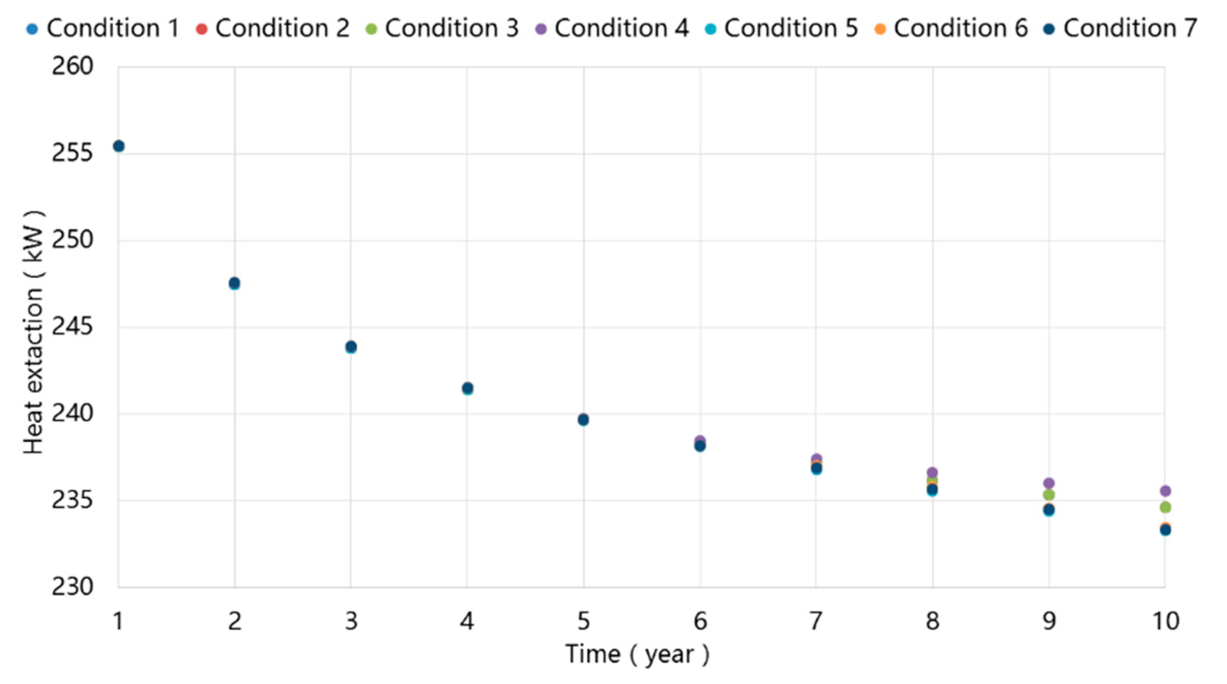
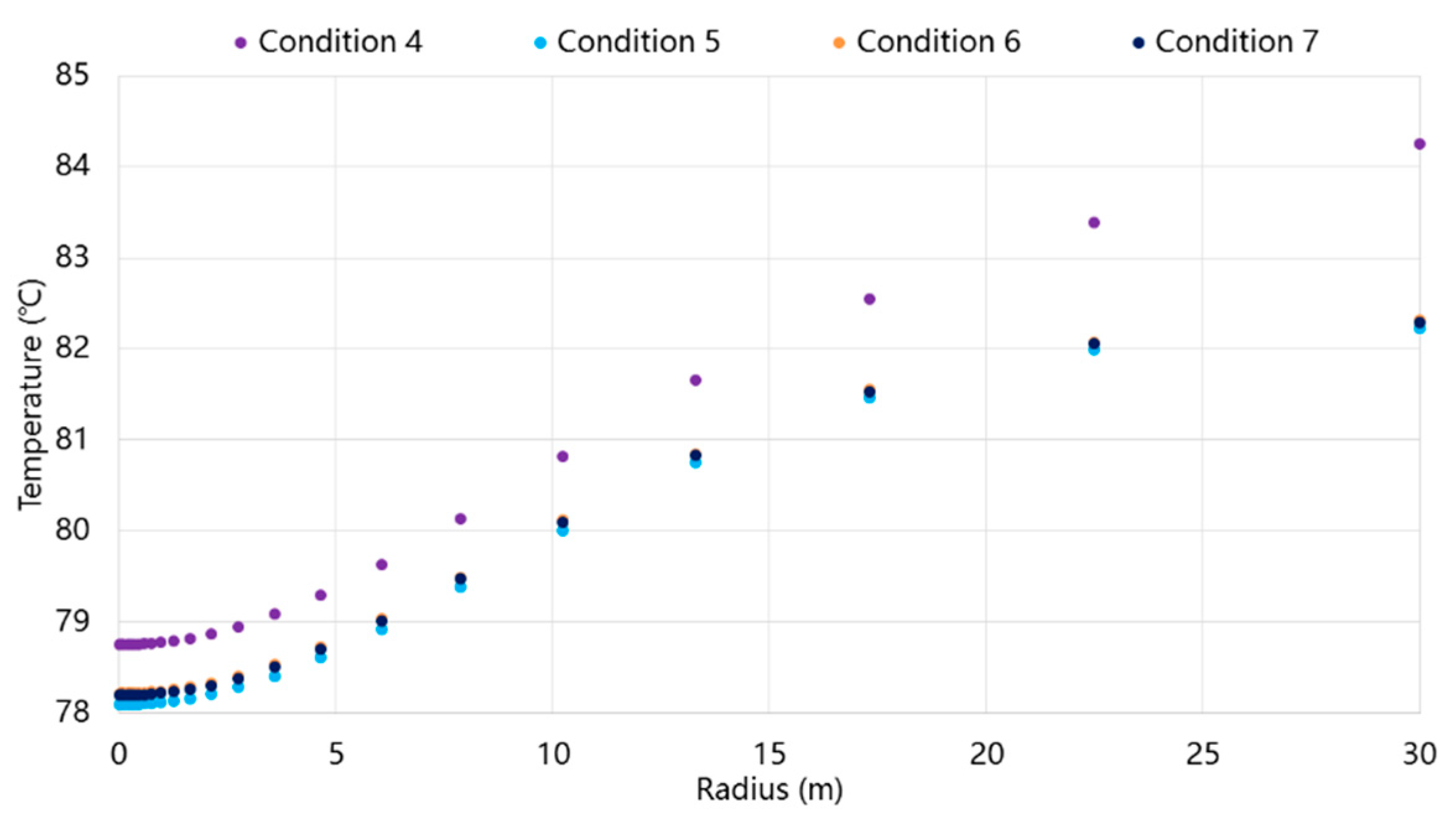
3.5. Comparison of Different Boundary Conditions on Simulation Results Under Long-Term Operation

In this paper, the constant heat flux condition is set at the bottom of the ground and the adiabatic condition is set at the radial far boundary. In order to analyze the influence of boundary condition on heat transfer performance of DBHEs. Simulations are conducted with different boundary conditions, while the inlet water temperature and flow rate are set the same as in Section 3.3. Figure 28 shows the variation of average heat extraction in long-term operation under different boundary conditions and the relevant condition sets are listed in Table 7.
It can be seen that, at the early stage, there is no obvious difference in heat extraction between those 7 different boundary conditions. However, since the 6th year, the difference becomes obvious gradually. Then at the end of 10-years operation, the annual average heat extraction of DBHE under condition 4 is the highest among those 7 different conditions. Then comes to the heat extraction under conditions 1–3 with nearly the same values. And the heat extraction under conditions 5–7 with nearly the same values are the lowest. The results show that the boundary condition of radial far boundary has more influence on heat transfer performance than boundary condition at bottom. As for the radial far boundary, if the radius of boundary is long enough, like 100 m or more, there is no obvious difference in the heat extraction between isothermal condition and adiabatic condition. However, in the practical project, there are more than one DBHE operating in parallel and the distance between adjacent DBHEs are lower than 50 m under the limit of space. Under this situation, the adiabatic condition is preferable.
Figure 29 then depicts the ground temperature distribution at the depth of 2500 m. It can be seen that the isothermal condition leads to the higher ground temperature, which then contributes to the higher water temperature and heat extraction of DBHEs. But when DBHEs operate in parallel, the ground temperature between the adjacent DBHEs will declines gradually as the DBHE continuously extract heat from the ground. Thus the isothermal radial far condition fails to depict the situation and adiabatic condition is closer to the practical situation. However, as for the boundary condition at the bottom, since the temperature of ground in depth direction from the bottom of DBHE is almost unaffected by other DBHEs, so the depth of boundary could be set deep enough, thus the constant flux boundary and isothermal condition have no obvious difference. But the former is closer to the practical physical process.
This also shows that directional drilling can be adopted to increase the distance between each DBHE, especially for the distance at deeper depth, thus the interaction effect could be reduced to attain higher heat extraction, as well as save space and cut rig cost.

4. Conclusions

In this paper, the heat transfer performance of DBHE are analyzed based on filed test and simulation results. The key conclusions are summarized as follows:
(1)
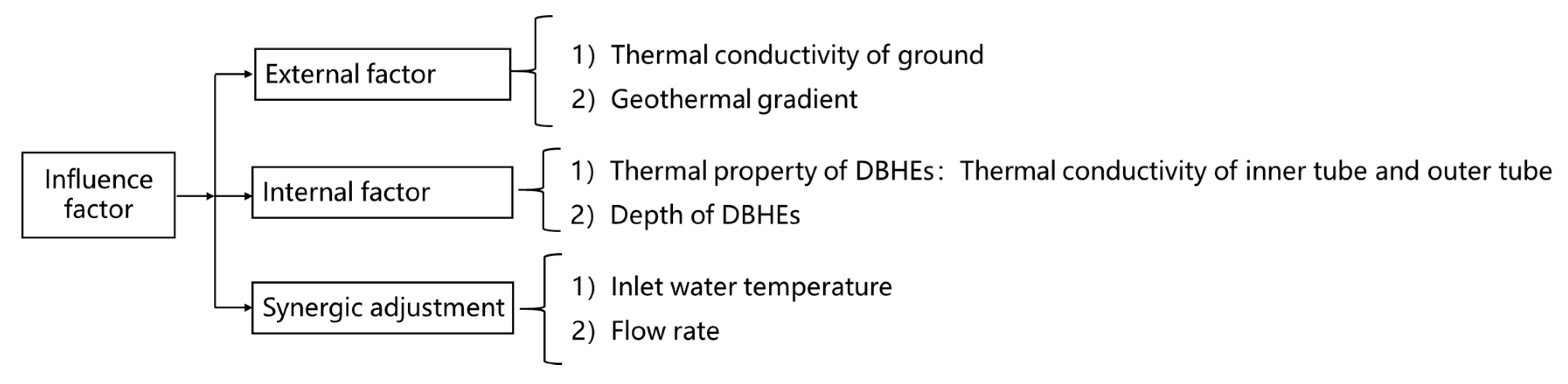
The influence factors on heat transfer performance of DBHEs could be classified into external factors, internal factors and synergic adjustment. The external factors refers to the local geothermal conditions, which could not be changed but should be investigated during the design period. As for the internal factors, the thermal conductivity of inner pipe should be decreased to avoid the heat loss and temperature drops. Besides, there is no need to improve the thermal conductivity of outer pipe when it is higher than 10 W/(m·K) or use different materials at different depth since the thermal resistance of ground plays a dominant role. Instead, the heat transfer area of outer tube should be increased to reduce the thermal resistance of the ground, where the increasing of depth has significant effect since the ground temperature rises at the same time. Then during the operation, the flow rate and inlet water temperature have great influence on heat extraction, which also influence the energy performance of MD-GHPs. Therefore, during the peak load period, the flow rate could be increased and inlet water temperature could be decreased to obtain higher heat extraction. Then during the part load period, the flow rate could be decreased to reduce the energy consumption of water pumps. Meanwhile, the inlet water temperature could be increased to increase the energy performance of heat pumps.
(2)
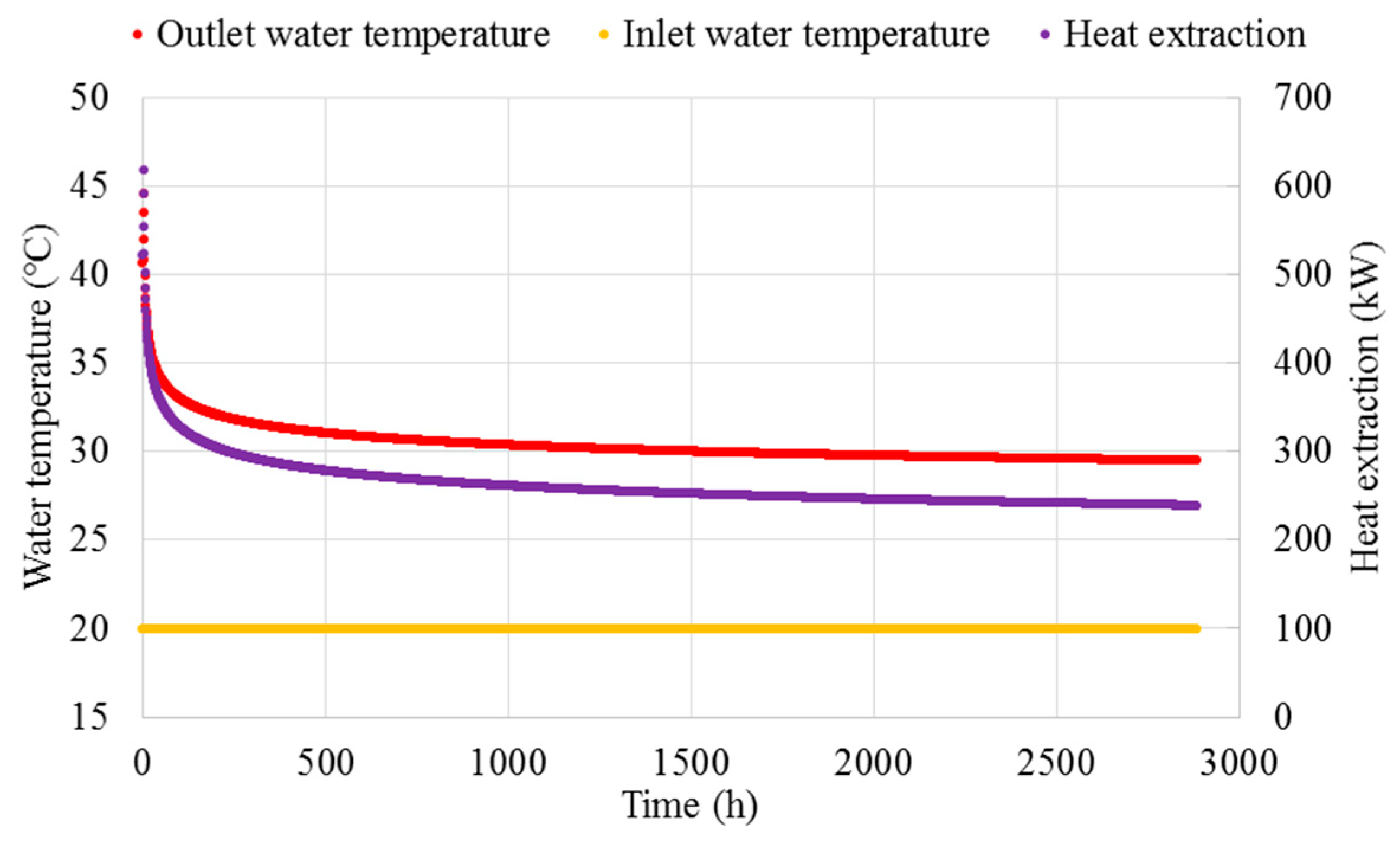
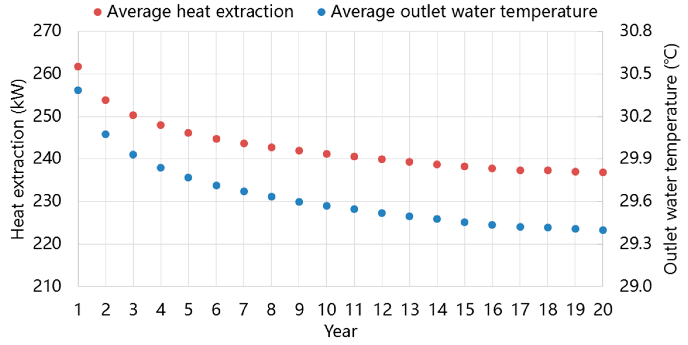
After 20-years operation, the average outlet water temperature drops only 0.99 °C and the average heat extraction drops only 9.5% with constant inlet water temperature and flow rate. Moreover, during practical operation, the operation parameters could be adjusted to increase the heat extraction to attain nearly the same value with the first heating season. Therefore, the medium-depth geothermal energy can serve as the high-temperature heat source for heat pump systems stably and reliably under long-term operation.
(3)
Under long-term operation, the ground temperature drops more at deeper place, thus interaction effect between adjacent DBHEs is more obvious at deeper place. Consequently, directional drilling can be applied to increase the distance between each DBHE at deeper place, thus the interaction effect could be reduced to attain higher heat extraction, as well as save space and cut rig cost.
The results from this study can be potentially used to guide the design and optimization of DBHEs of MD-GHPs. In summary, the MD-GHPs has a high-temperature and stable heat source, which saves the space occupation of DBHEs greatly and improves the performance of the system obviously. However, there are still a lot of work to do about this space heating technology from system design to the operations and managements, thus it can be regarded as a potentially efficient and economic approach for space heating in cold regions.

Author Contributions

Supervision, Q.W.; project administration, H.Z.; Methodology, J.D., S.H., M.L.; writing—original draft preparation, J.D. All authors have read and agreed to the published version of the manuscript.

Funding

This research was funded by the National Key R&D Program of China, grant number 2017YFC0704200 and the National Natural Science Foundation of China, grant number 51,521,005.

Conflicts of Interest

The authors declare no conflict of interest.

Nomenclature

a–nConstant coefficient r i i Inner surface radius of inner pipe, m
A i n Cross-section area of inner pipe, m2 r i o Outer surface radius of inner pipe, m
A i j Cross-section area of ground (i,j), m2 r o i Inner surface radius of outer pipe, m
A o Cross-section area of outer pipe, m2 r o o Outer surface radius of outer pipe, m
C f Heat capacity of inner pipe fluid, kJ/(kg*K) r 4 Radius of the center of grout, m
C g Ground heat capacity, kJ/(kg·K) r 5 r N Radius of the ground, m
d o Equivalent meter of outer pipe, mRcContact thermal resistance, W/(m·K)
D Geothermal gradient, °C/hm R e , i i Reynolds numbers of inner surface of inner pipe
f Wetted perimeter of outer pipe, m R e , i o Reynolds numbers of outer surface of inner pipe
G Flow rate, m3/h R e , o i Reynolds numbers of inner surface of outer pipe
h 1 Convective heat transfer coefficients of the inner surface of inner pipe, W/(m2·K) T f , i n Inner pipe fluid temperature, °C
h 2 Convective heat transfer coefficients of the outer surface of inner pipe, W/(m2·K) T f , o Outer pipe fluid temperature, °C
h 3 Convective heat transfer coefficients of the inner surface of outer pipe, W/(m2·K)TgGround temperature, °C
H E Depth of DBHEs, mTgroutTemperature of grout surrounding the DBHE, °C
H b Depth of bottom boundary, m T g , 0 Ground surface temperature, °C
K i Equivalent thermal conductivity of the unit length of the inner pipe, W/(m·K) T i n Inlet water temperature. °C
K o Equivalent thermal conductivity of the unit length of the outer pipe, W/(m·K) T o , f Field test outlet water temperature, °C
N u , i i Nusselt number of inner surface of inner pipe T o , f , m a x Maximum of field test outlet water temperature, °C
N u , i o Nusselt number of outer surface of inner pipe T o , f , m i n Minimum of field test outlet water temperature, °C
N u , o i Nusselt number of inner surface of outer pipe T o , s Simulation outlet water temperature, °C
p Constant coefficient u i n Flow velocity of inner pipe fluid, m/s
P r Prandtl number of water u o Flow velocity of outer pipe fluid, m/s
qcGround heat flux, W/m2zDepth direction parameter, m
rRadius direction parameter, m Δ z Depth of each mesh, m
r g o Radius of the boundary of grout, m

Greek Letter

ρ f Density of inner pipe fluid, kg/m3 λ o Thermal conductivity of the outer pipe wall, W/(m·K)
ρ g Ground density, kg/m3 τ Time parameter, s
λ f Thermal conductivity of the water, W/(m·K)∆τTime step, s
λ g Ground thermal conductivity, W/(m·K) δ Relative error, %
λ i n Thermal conductivity of the inner pipe, W/(m·K)

Abbreviations

BHEsBorehole heat exchangersFVMFinite volume method
COPCoefficient of performanceGCHPsGround-coupled heat pump systems
DBHEsDeep borehole heat exchangersGHEsGround heat exchangers
FDMFinite difference methodMD-GHPsMedium-depth geothermal heat pumps system
FEMFinite element method

References

  1. Building Energy Conservation Research Center. 2019 Annual Report on China Building Energy Efficiency, 1st ed.; China Architecture & Building Press: Beijing, China, 2019. [Google Scholar]
  2. Lund, J.W.; Boyd, T.L. Direct utilization of geothermal energy 2015 worldwide review. Geothermics 2016, 60, 66–93. [Google Scholar] [CrossRef]
  3. Self, S.J.; Reddy, B.V.; Rosen, M.A. Geothermal heat pump systems: Status review and comparison with other heating options. Appl. Energy 2013, 101, 341–348. [Google Scholar] [CrossRef]
  4. Liu, Z.; Xu, W.; Qian, C.; Chen, X.; Jin, G. Investigation on the feasibility and performance of ground source heat pump (GSHP) in three cities in cold climate zone, China. Renew. Energy 2015, 84, 89–96. [Google Scholar] [CrossRef]
  5. Wu, W.; Wang, B.; You, T.; Shi, W.; Li, X. A potential solution for thermal imbalance of ground source heat pump systems in cold regions: Ground source absorption heat pump. Renew. Energy 2013, 59, 39–48. [Google Scholar] [CrossRef]
  6. Rad, F.M.; Fung, A.S.; Leong, W.H. Feasibility of combined solar thermal and ground source heat pump systems in cold climate, Canada. Energy Build. 2013, 61, 224–232. [Google Scholar] [CrossRef]
  7. Verma, V.; Murugesan, K. Experimental study of solar energy storage and space heating using solar assisted ground source heat pump system for Indian climatic conditions. Energy Build. 2017, 139, 569–577. [Google Scholar] [CrossRef]
  8. Han, Z.; Zheng, M.; Kong, F.; Wang, F.; Li, Z.; Bai, T. Numerical simulation of solar assisted ground-source heat pump heating system with latent heat energy storage in severely cold area. Appl. Therm. Eng. 2008, 28, 1427–1436. [Google Scholar] [CrossRef]
  9. You, T.; Wang, B.L.; Wu, W.; Shi, W.X.; Li, X.T. A new solution for underground thermal imbalance of ground-coupled heat pump systems in cold regions: Heat compensation unit with thermosiphon. Appl. Therm. Eng. 2014, 64, 283–292. [Google Scholar] [CrossRef]
  10. Morita, K.; Bollmeier, W.S.; Mizogami, H. An experiment to prove the concept of the downhole coaxial heat exchanger (DCHE) in Hawaii. GRC Trans. 1992, 16, 9–16. [Google Scholar]
  11. Kohl, T.; Brenni, R.; Eugster, W. System performance of a deep borehole heat exchanger. Geothermics 2002, 31, 687–708. [Google Scholar] [CrossRef]
  12. Dijkshoorn, L.; Speer, S.; Pechnig, R. Measurements and Design Calculations for a Deep Coaxial Borehole Heat Exchanger in Aachen, Germany. Int. J. Geophys. 2013, 2013, 1–14. [Google Scholar] [CrossRef]
  13. Deng, J.; Wei, Q.; Liang, M.; He, S.; Zhang, H. Field test on energy performance of medium-depth geothermal heat pump systems (MD-GHPs). Energy Build. 2019, 184, 289–299. [Google Scholar] [CrossRef]
  14. Ingersoll, L.R.; Plass, H.J. Theory of the ground pipe heat source for the heat pump. ASHRAE Trans. 1948, 47, 339–348. [Google Scholar]
  15. Eskilson, P. Thermal Analysis of Heat Extraction Boreholes; Lund University: Lund, Sweden, 1987. [Google Scholar]
  16. Diao, N.R.; Zeng, H.Y.; Fang, Z.H. Improvement in Modeling of Heat Transfer in Vertical Ground Heat Exchangers. HVAC&R Res. 2004, 10, 459–470. [Google Scholar]
  17. Lamarche, L.; Beauchamp, B. A new contribution to the finite line-source model for geothermal boreholes. Energy Build. 2007, 39, 188–198. [Google Scholar] [CrossRef]
  18. Jahangir, M.H.; Sarrafha, H.; Kasaeian, A. Numerical modeling of energy transfer in underground borehole heat exchanger within unsaturated soil. Appl. Therm. Eng. 2018, 132, 697–707. [Google Scholar] [CrossRef]
  19. Li, Z.; Zheng, M. Development of a numerical model for the simulation of vertical U-pipe ground heat exchangers. Appl. Therm. Eng. 2009, 29, 920–924. [Google Scholar] [CrossRef]
  20. Mottaghy, D.; Dijkshoorn, L. Implementing an effective finite difference formulation for borehole heat exchangers into a heat and mass transport code. Renew. Energy 2012, 45, 59–71. [Google Scholar] [CrossRef]
  21. Beier, R.A.; Acuña, J.; Mogensen, P.; Palm, B. Transient heat transfer in a coaxial borehole heat exchanger. Geothermics 2014, 51, 470–482. [Google Scholar] [CrossRef]
  22. Chen, S.; Mao, J.; Han, X. Heat transfer analysis of a vertical ground heat exchanger using numerical simulation and multiple regression model. Energy Build. 2016, 129, 81–91. [Google Scholar] [CrossRef]
  23. Holmberg, H.; Acuña, J.; Næss, E.; Sønju, O.K. Thermal evaluation of coaxial deep borehole heat exchangers. Renew. Energy 2016, 97, 65–76. [Google Scholar] [CrossRef]
  24. Le Lous, M.; Larroque, F.; Dupuy, A.; Moignard, A. Thermal performance of a deep borehole heat exchanger: Insights from a synthetic coupled heat and flow model. Geothermics 2015, 57, 157–172. [Google Scholar] [CrossRef]
  25. Fang, L.; Diao, N.; Shao, Z.; Zhu, K.; Fang, Z. A computationally efficient numerical model for heat transfer simulation of deep borehole heat exchangers. Energy Build. 2018, 167, 79–88. [Google Scholar] [CrossRef]
  26. Kong, Y.L.; Chen, C.F.; Shao, H.B.; Pang, Z.H.; Xiong, L.P.; Wang, J.Y. Principle and capacity quantification of deep-borehole heat exchangers. Chin. J. Geophys. 2017, 60, 4741–4752. [Google Scholar]
  27. Wang, Z.; Wang, F.; Liu, J.; Ma, Z.; Han, E.; Song, M. Field test and numerical investigation on the heat transfer characteristics and optimal design of the heat exchangers of a deep borehole ground source heat pump system. Energy Convers. Manag. 2017, 153, 603–615. [Google Scholar] [CrossRef]
  28. Cai, W.; Wang, F.; Liu, J.; Wang, Z.; Ma, Z. Experimental and numerical investigation of heat transfer performance and sustainability of deep borehole heat exchangers coupled with ground source heat pump systems. Appl. Therm. Eng. 2019, 149, 975–986. [Google Scholar] [CrossRef]
  29. Liu, J.; Wang, F.; Cai, W.; Wang, Z.; Wei, Q.; Deng, J. Numerical study on the effects of design parameters on the heat transfer performance of coaxial deep borehole heat exchanger. Int. J. Energy Res. 2019, 43, 6337–6352. [Google Scholar] [CrossRef]
  30. Wang, W.Y.; Huang, S.Y. Research on the Basic Theory of Geothermal; Geological Publishing House: Beijing, China, 1982; pp. 12–16. [Google Scholar]
  31. Xu, S.G.; Guo, Y.S. Fundamentals of Geothermics; Science Press: Beijing, China, 2009; pp. 10–12. [Google Scholar]
  32. Jiang, G.Z.; Gao, P.; Rao, S.; Zhang, L.Y.; Tang, X.Y.; Huang, F.; Zhao, P.; Pang, Z.H.; He, L.J.; Hu, S.B.; et al. Compilation of heat flow data in the continental area of China (4th edition). Chin. J. Geophys. 2016, 59, 2892–2910. [Google Scholar]
  33. Mai, G.; Gao, Y. Well Completion Report of Deep Geothermal; University of Architecture and Technology: Xi’an, China, 2000. [Google Scholar]
  34. Wang, J.Y. Geothermics and Its Applications; Science Press: Beijing, China, 2015. [Google Scholar]
  35. Zhan, G.H. Study of Heat Transfer Model outside the Borehole of Vertical U-Tube of Ground-Coupled Heat Pump; Zhejiang University: Hangzhou, China, 2011. [Google Scholar]
Figure 1. System diagram and measuring points of medium-depth geothermal heat pumps system (MD-GHPs).
Energies 13 00754 g001
Figure 2. A diagram of the deep borehole heat exchangers (DBHEs).
Energies 13 00754 g002
Figure 3. Model of deep borehole heat exchangers (DBHEs).
Energies 13 00754 g003
Figure 4. Discretization meshes of DBHEs and ground.
Energies 13 00754 g004
Figure 5. The ground temperature distribution at the depth of 2530–2700 m.
Energies 13 00754 g005
Figure 6. The ground temperature distribution in radius direction at the bottom of DBHEs.
Energies 13 00754 g006
Figure 7. Field tests result of DBHE.
Energies 13 00754 g007
Figure 8. Comparison of field test values and simulation values.
Energies 13 00754 g008
Figure 9. Continuous heat transfer performance of DBHEs in a heating season.
Energies 13 00754 g009
Figure 10. The calculated water temperature distribution in DBHE.
Energies 13 00754 g010
Figure 11. Heat transfer per length of the DBHE.
Energies 13 00754 g011
Figure 12. Influence factors of heat transfer performance.
Energies 13 00754 g012
Figure 13. The water temperature distribution under different ground thermal conductivity.
Energies 13 00754 g013
Figure 14. Effect of ground thermal conductivity on the water temperature difference.
Energies 13 00754 g014
Figure 15. Effect of ground thermal conductivity on the heat extraction of DBHEs.
Energies 13 00754 g015
Figure 16. Effect of geothermal gradient on the water temperature difference.
Energies 13 00754 g016
Figure 17. Effect of geothermal gradient on the heat extraction of DBHEs.
Energies 13 00754 g017
Figure 18. Effect of thermal conductivity of inner pipe on the water temperature distribution.
Energies 13 00754 g018
Figure 19. Effect of thermal conductivity of inner pipe on the heat extraction of DBHEs.
Energies 13 00754 g019
Figure 20. Effect of thermal conductivity of outer pipe on the water temperature difference.
Energies 13 00754 g020
Figure 21. Effect of thermal conductivity of outer pipe on the heat extraction of DBHEs.
Energies 13 00754 g021
Figure 22. Effect of thermal conductivity of outer pipe at 0–300 m on the heat extraction of DBHEs.
Energies 13 00754 g022
Figure 23. Effect of DBHEs depth on the water temperature distribution.
Energies 13 00754 g023
Figure 24. Effect of DBHEs depth on the heat extraction.
Energies 13 00754 g024
Figure 25. Effect of inlet water temperature and flow rate on the heat extraction.
Energies 13 00754 g025
Figure 26. Variation of outlet water temperature and heat extraction in 10-years of operation.
Energies 13 00754 g026
Figure 27. Ground temperature variation after 20-years of operation.
Energies 13 00754 g027
Figure 28. Variation of heat extraction in long-term with different boundary conditions.
Energies 13 00754 g028
Figure 29. Ground temperature distribution at the depth of 2500 m with different boundary conditions.
Energies 13 00754 g029
Table 1. Basic information of field tested project.
Building FunctionResidential Buildings
Designed building area (m2)133,400
Actual heating area (m2).53,360
Type of heat pumpScrew heat pump
Number of heat pumps2
Rated heating capacity (kW)5680
Rated COP5.68
Number of DBHEs.8
Depth of DBHEs (m)2500
Designed water temperature in user side (°C)45/40
Designed water temperature ground side (°C)30/20
Terminal deviceRadiant floor
Operational modeContinuous
Heating season15th November–15st March
Table 2. The physical dimension and thermo-physical property of the DBHE.
ParametersNumerical Value
Depth of DBHE (m)2500
Outside diameter × wall thickness (mm × mm)159 × 4.5
Thermal conductivity of the outer pipe W/(m·K)54
Specific heat capacity of the outer pipe kJ/(kg·K)0.47
Density of the outer pipe kg/m37820
Inside diameter × wall thickness (mm × mm)93 × 3.0
Thermal conductivity of the inner pipe W/(m·K)0.18
Specific heat capacity of the inner pipe kJ/(kg·K)2.1
Density of the inner pipe kg/m3930
Diameter of backfill materials (mm)254
Thermal conductivity of the backfill materials W/(m·K)2.0
Specific heat capacity of the backfill materials kJ/(kg·K)0.85
Density of the backfill materials kg/m32700
Table 3. The physical dimension and thermo-physical property of the soil and rocks.
Depth mGeotechnical TypeThermal Conductivity W/(m·K)Density kg/m³Specific Heat Capacity J/(kg·K)
0–636Clay1.817801379
636–1198Mudstone2.620301450
1198–1910Medium sand3.515101300
1910–3000Standstone5.32600878
Table 4. Mesh independence analysis on space steps and time step
p Outlet Water Temperature (°C) Δ z
(m)
Outlet Water Temperature (°C) Δ τ   ( s ) Outlet Water Temperature (°C)
1.129.714129.7146029.714
1.229.714529.71460029.714
1.329.7161029.728360029.715
1.429.7292529.747720029.741
1.529.7525029.78618,00029.832
Table 5. Constant coefficients by regression from simulation results.
abcdefg
78.78−0.233920.671.32×10−10−4.363−0.169−0.0244
hijklmn
0.33170.20690.4214−0.19892.0 ×10−72.0 × 10⁻⁵−0.0596
Table 6. The ranges of each independent variables.
VariablesSuggested Min ValueSuggested Max ValueThe value Used in This Paper
λ g (W/(m·K))2.04.53.0
D (°C/hm)1.54.03.0
H E (m)100030002500
G (kg/s)2.012.06.0
T i n (°C)5.030.020.0
Table 7. Boundary condition set of radial far boundary and bottom boundary.
ConditionsRadius
(m)
Radial Far
Boundary Condition
Depth from Bottom
of DBHE (m)
Bottom Boundary Condition
1100Isothermal condition200Isothermal condition
2100Adiabatic condition200Isothermal condition
3100Adiabatic condition200Constant heat flux
430Isothermal condition200Constant heat flux
530Adiabatic condition200Constant heat flux
630Adiabatic condition50Isothermal condition
730Adiabatic condition50Constant heat flux

